EP3214039B1 - Wasserstofferzeugungsvorrichtung, verfahren zum betrieb davon und brennstoffzellensystem - Google Patents
Wasserstofferzeugungsvorrichtung, verfahren zum betrieb davon und brennstoffzellensystem Download PDFInfo
- Publication number
- EP3214039B1 EP3214039B1 EP15855017.8A EP15855017A EP3214039B1 EP 3214039 B1 EP3214039 B1 EP 3214039B1 EP 15855017 A EP15855017 A EP 15855017A EP 3214039 B1 EP3214039 B1 EP 3214039B1
- Authority
- EP
- European Patent Office
- Prior art keywords
- amount
- hydrogen
- raw material
- gas
- supply device
- Prior art date
- Legal status (The legal status is an assumption and is not a legal conclusion. Google has not performed a legal analysis and makes no representation as to the accuracy of the status listed.)
- Active
Links
Images



Classifications
-
- C—CHEMISTRY; METALLURGY
- C01—INORGANIC CHEMISTRY
- C01B—NON-METALLIC ELEMENTS; COMPOUNDS THEREOF; METALLOIDS OR COMPOUNDS THEREOF NOT COVERED BY SUBCLASS C01C
- C01B3/00—Hydrogen; Gaseous mixtures containing hydrogen; Separation of hydrogen from mixtures containing it; Purification of hydrogen; Reversible storage of hydrogen
- C01B3/02—Production of hydrogen; Production of gaseous mixtures containing hydrogen
- C01B3/32—Production of hydrogen; Production of gaseous mixtures containing hydrogen by reaction of gaseous or liquid organic compounds with gasifying agents, e.g. water, carbon dioxide or air
- C01B3/34—Production of hydrogen; Production of gaseous mixtures containing hydrogen by reaction of gaseous or liquid organic compounds with gasifying agents, e.g. water, carbon dioxide or air by reaction of hydrocarbons with gasifying agents
- C01B3/38—Production of hydrogen; Production of gaseous mixtures containing hydrogen by reaction of gaseous or liquid organic compounds with gasifying agents, e.g. water, carbon dioxide or air by reaction of hydrocarbons with gasifying agents using catalysts
- C01B3/384—Production of hydrogen; Production of gaseous mixtures containing hydrogen by reaction of gaseous or liquid organic compounds with gasifying agents, e.g. water, carbon dioxide or air by reaction of hydrocarbons with gasifying agents using catalysts with external heating of the catalyst
-
- B—PERFORMING OPERATIONS; TRANSPORTING
- B01—PHYSICAL OR CHEMICAL PROCESSES OR APPARATUS IN GENERAL
- B01J—CHEMICAL OR PHYSICAL PROCESSES, e.g. CATALYSIS OR COLLOID CHEMISTRY; THEIR RELEVANT APPARATUS
- B01J23/00—Catalysts comprising metals or metal oxides or hydroxides, not provided for in group B01J21/00
- B01J23/38—Catalysts comprising metals or metal oxides or hydroxides, not provided for in group B01J21/00 of noble metals
- B01J23/40—Catalysts comprising metals or metal oxides or hydroxides, not provided for in group B01J21/00 of noble metals of the platinum group metals
- B01J23/46—Ruthenium, rhodium, osmium or iridium
-
- H—ELECTRICITY
- H01—ELECTRIC ELEMENTS
- H01M—PROCESSES OR MEANS, e.g. BATTERIES, FOR THE DIRECT CONVERSION OF CHEMICAL ENERGY INTO ELECTRICAL ENERGY
- H01M8/00—Fuel cells; Manufacture thereof
- H01M8/06—Combination of fuel cells with means for production of reactants or for treatment of residues
- H01M8/0606—Combination of fuel cells with means for production of reactants or for treatment of residues with means for production of gaseous reactants
- H01M8/0612—Combination of fuel cells with means for production of reactants or for treatment of residues with means for production of gaseous reactants from carbon-containing material
-
- C—CHEMISTRY; METALLURGY
- C01—INORGANIC CHEMISTRY
- C01B—NON-METALLIC ELEMENTS; COMPOUNDS THEREOF; METALLOIDS OR COMPOUNDS THEREOF NOT COVERED BY SUBCLASS C01C
- C01B2203/00—Integrated processes for the production of hydrogen or synthesis gas
- C01B2203/02—Processes for making hydrogen or synthesis gas
- C01B2203/0205—Processes for making hydrogen or synthesis gas containing a reforming step
- C01B2203/0227—Processes for making hydrogen or synthesis gas containing a reforming step containing a catalytic reforming step
- C01B2203/0233—Processes for making hydrogen or synthesis gas containing a reforming step containing a catalytic reforming step the reforming step being a steam reforming step
-
- C—CHEMISTRY; METALLURGY
- C01—INORGANIC CHEMISTRY
- C01B—NON-METALLIC ELEMENTS; COMPOUNDS THEREOF; METALLOIDS OR COMPOUNDS THEREOF NOT COVERED BY SUBCLASS C01C
- C01B2203/00—Integrated processes for the production of hydrogen or synthesis gas
- C01B2203/04—Integrated processes for the production of hydrogen or synthesis gas containing a purification step for the hydrogen or the synthesis gas
- C01B2203/0435—Catalytic purification
- C01B2203/044—Selective oxidation of carbon monoxide
-
- C—CHEMISTRY; METALLURGY
- C01—INORGANIC CHEMISTRY
- C01B—NON-METALLIC ELEMENTS; COMPOUNDS THEREOF; METALLOIDS OR COMPOUNDS THEREOF NOT COVERED BY SUBCLASS C01C
- C01B2203/00—Integrated processes for the production of hydrogen or synthesis gas
- C01B2203/06—Integration with other chemical processes
- C01B2203/066—Integration with other chemical processes with fuel cells
-
- C—CHEMISTRY; METALLURGY
- C01—INORGANIC CHEMISTRY
- C01B—NON-METALLIC ELEMENTS; COMPOUNDS THEREOF; METALLOIDS OR COMPOUNDS THEREOF NOT COVERED BY SUBCLASS C01C
- C01B2203/00—Integrated processes for the production of hydrogen or synthesis gas
- C01B2203/08—Methods of heating or cooling
- C01B2203/0805—Methods of heating the process for making hydrogen or synthesis gas
- C01B2203/0811—Methods of heating the process for making hydrogen or synthesis gas by combustion of fuel
- C01B2203/0827—Methods of heating the process for making hydrogen or synthesis gas by combustion of fuel at least part of the fuel being a recycle stream
-
- C—CHEMISTRY; METALLURGY
- C01—INORGANIC CHEMISTRY
- C01B—NON-METALLIC ELEMENTS; COMPOUNDS THEREOF; METALLOIDS OR COMPOUNDS THEREOF NOT COVERED BY SUBCLASS C01C
- C01B2203/00—Integrated processes for the production of hydrogen or synthesis gas
- C01B2203/10—Catalysts for performing the hydrogen forming reactions
- C01B2203/1041—Composition of the catalyst
- C01B2203/1047—Group VIII metal catalysts
- C01B2203/1064—Platinum group metal catalysts
-
- C—CHEMISTRY; METALLURGY
- C01—INORGANIC CHEMISTRY
- C01B—NON-METALLIC ELEMENTS; COMPOUNDS THEREOF; METALLOIDS OR COMPOUNDS THEREOF NOT COVERED BY SUBCLASS C01C
- C01B2203/00—Integrated processes for the production of hydrogen or synthesis gas
- C01B2203/12—Feeding the process for making hydrogen or synthesis gas
- C01B2203/1205—Composition of the feed
- C01B2203/1211—Organic compounds or organic mixtures used in the process for making hydrogen or synthesis gas
- C01B2203/1235—Hydrocarbons
- C01B2203/1241—Natural gas or methane
-
- C—CHEMISTRY; METALLURGY
- C01—INORGANIC CHEMISTRY
- C01B—NON-METALLIC ELEMENTS; COMPOUNDS THEREOF; METALLOIDS OR COMPOUNDS THEREOF NOT COVERED BY SUBCLASS C01C
- C01B2203/00—Integrated processes for the production of hydrogen or synthesis gas
- C01B2203/12—Feeding the process for making hydrogen or synthesis gas
- C01B2203/1258—Pre-treatment of the feed
- C01B2203/1264—Catalytic pre-treatment of the feed
- C01B2203/127—Catalytic desulfurisation
-
- C—CHEMISTRY; METALLURGY
- C01—INORGANIC CHEMISTRY
- C01B—NON-METALLIC ELEMENTS; COMPOUNDS THEREOF; METALLOIDS OR COMPOUNDS THEREOF NOT COVERED BY SUBCLASS C01C
- C01B2203/00—Integrated processes for the production of hydrogen or synthesis gas
- C01B2203/16—Controlling the process
- C01B2203/1642—Controlling the product
- C01B2203/1647—Controlling the amount of the product
- C01B2203/1652—Measuring the amount of product
- C01B2203/1657—Measuring the amount of product the product being hydrogen
-
- C—CHEMISTRY; METALLURGY
- C01—INORGANIC CHEMISTRY
- C01B—NON-METALLIC ELEMENTS; COMPOUNDS THEREOF; METALLOIDS OR COMPOUNDS THEREOF NOT COVERED BY SUBCLASS C01C
- C01B2203/00—Integrated processes for the production of hydrogen or synthesis gas
- C01B2203/16—Controlling the process
- C01B2203/169—Controlling the feed
-
- Y—GENERAL TAGGING OF NEW TECHNOLOGICAL DEVELOPMENTS; GENERAL TAGGING OF CROSS-SECTIONAL TECHNOLOGIES SPANNING OVER SEVERAL SECTIONS OF THE IPC; TECHNICAL SUBJECTS COVERED BY FORMER USPC CROSS-REFERENCE ART COLLECTIONS [XRACs] AND DIGESTS
- Y02—TECHNOLOGIES OR APPLICATIONS FOR MITIGATION OR ADAPTATION AGAINST CLIMATE CHANGE
- Y02E—REDUCTION OF GREENHOUSE GAS [GHG] EMISSIONS, RELATED TO ENERGY GENERATION, TRANSMISSION OR DISTRIBUTION
- Y02E60/00—Enabling technologies; Technologies with a potential or indirect contribution to GHG emissions mitigation
- Y02E60/30—Hydrogen technology
- Y02E60/50—Fuel cells
-
- Y—GENERAL TAGGING OF NEW TECHNOLOGICAL DEVELOPMENTS; GENERAL TAGGING OF CROSS-SECTIONAL TECHNOLOGIES SPANNING OVER SEVERAL SECTIONS OF THE IPC; TECHNICAL SUBJECTS COVERED BY FORMER USPC CROSS-REFERENCE ART COLLECTIONS [XRACs] AND DIGESTS
- Y02—TECHNOLOGIES OR APPLICATIONS FOR MITIGATION OR ADAPTATION AGAINST CLIMATE CHANGE
- Y02P—CLIMATE CHANGE MITIGATION TECHNOLOGIES IN THE PRODUCTION OR PROCESSING OF GOODS
- Y02P20/00—Technologies relating to chemical industry
- Y02P20/50—Improvements relating to the production of bulk chemicals
- Y02P20/52—Improvements relating to the production of bulk chemicals using catalysts, e.g. selective catalysts
Definitions
- the present invention relates to a hydrogen generation apparatus that generates hydrogen by reforming a hydrocarbon-containing raw material gas, a method of driving the same, and a fuel cell system including a fuel cell that performs power generation by using a hydrogen-containing gas that is obtained with the hydrogen generation apparatus.
- a fuel cell that is capable of performing high-efficiency power generation even in a small-sized apparatus is a power generation apparatus that is a distributed energy supply source.
- a hydrogen gas that is used as fuel during power generation in the fuel cell is not serviced by a typical infrastructure.
- a configuration, in which a hydrogen generation apparatus is arranged in combination with the fuel cell is employed in many cases.
- the hydrogen generation apparatus subjects a hydrocarbon-containing raw material gas such as a city gas and LPG, which are obtained from an existing fossil raw material infrastructure, to a steam reforming reaction to generate a hydrogen-containing gas.
- a composition of a gas which is used as a raw material, may vary in accordance with an infrastructure configuration.
- a composition thereof may be different in accordance with a gas distribution company and an area, and the composition may vary with the passage of time.
- the amount of hydrogen generation in the hydrogen generation apparatus decreases.
- the amount of hydrogen becomes deficient, and thus it is difficult to maintain power generation.
- the amount of heat decreases due to deficiency in hydrogen. Accordingly, a temperature of the reformer is lowered, and thus it is difficult to maintain the reaction.
- WO2014082768A1 relates to a method for operating a fuel cell system, which has a fuel cell stack with at least one fuel cell and a reformer.
- an object of the invention is to provide a fuel cell system comprising a hydrogen generation apparatus in which the amount of hydrogen generated is appropriately maintained and stable driving is possible, and a method of driving the hydrogen generation apparatus.
- the amount of the hydrogen-containing gas generated varies in accordance with a variation in the composition of the raw material gas, and thus it is possible to instantly detect the variation in the composition of the raw material gas by detecting the variation in the amount of the hydrogen-containing gas generated.
- a control parameter corresponding to the composition of the raw material gas is set on the basis of the resultant detection result, the amount of hydrogen generated is appropriately maintained, and thus it is possible to realize a hydrogen generation apparatus and a fuel cell system which are capable of being stably driven.
- the amount of the hydrogen-containing gas generated varies in accordance with a variation in the composition of the raw material gas, and thus it is possible to instantly detect the variation in the composition of the raw material gas by detecting the variation in the amount of the hydrogen-containing gas generated.
- a control parameter corresponding to the composition of the raw material gas is set on the basis of the resultant detection result, the amount of hydrogen generated is appropriately maintained, and thus it is possible to realize a method of driving a hydrogen generation apparatus capable of being stably driven.
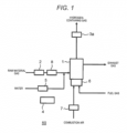
- FIG. 1 is a view illustrating a schematic configuration of hydrogen generation apparatus 50 according to the first exemplary embodiment not part of the claimed invention.
- hydrogen generation apparatus 50 includes reforming unit 1 that reforms a hydrocarbon-containing raw material gas to generate a hydrogen-containing gas, raw material supply device 2 that supplies the raw material to reforming unit 1, hydrogen-containing gas flow meter 3a as a hydrogen generation amount detection unit that detects the amount of the hydrogen-containing gas generated, and controller 4.
- controller 4 is configured to drive respective constituent elements, which include at least raw material supply device 2, of hydrogen generation apparatus 50 by setting a control parameter corresponding to a relatively low heat amount gas in a case where the amount of the hydrogen-containing gas generated decreases, and by setting a control parameter corresponding to a relatively high heat amount gas in a case where the amount of the hydrogen-containing gas generated increases.
- a steam reforming reaction which reforms hydrocarbon and steam
- an Ru-based catalyst is used as a reforming catalyst that fills reforming unit 1.
- water may be supplied to reforming unit 1 by water supply device 5.
- the steam reforming reaction is exemplified as the reforming reaction.
- the same effect is also obtained with other reactions such as an autothermal reaction and a partial oxidation reforming reaction.
- Reforming unit 1 may have a structure that is heated by heat transfer from combustor 6, or an outer side of reforming unit 1 may be covered with a heat insulating material.
- a raw material gas or a hydrogen-containing gas may be combusted.
- combustion air may be supplied to combustor 6 by combustion air supply device 7.
- hydrogen-containing gas flow meter 3a for the hydrogen-containing gas is provided as a hydrogen generation amount detection unit.
- Hydrogen-containing gas flow meter 3a is designed on the assumption of a predetermined composition of the hydrogen-containing gas, and is configured to output a signal of the flow rate and detect the amount of the hydrogen-containing gas generated from the output signal.
- Controller 4 of the hydrogen generation apparatus controls raw material supply device 2 to supply the raw material gas to reforming unit 1.
- a buster pump that raises a pressure of the raw material gas is used as raw material supply device 2
- a flow meter for the raw material gas is used as raw material flow rate detector 8.
- controller 4 is configured to control raw material supply device 2 in order for the flow rate of the raw material gas to be a predetermined flow rate.
- the raw material gas may be supplied in a state in which a sulfur component in the raw material gas is desulfurized after passing through a desulfurizer.
- the flow rate of the raw material gas may be set on the basis of a flow rate of a hydrogen-containing gas or a hydrogen gas to be generated in consideration of the composition of the raw material gas.
- the flow rate is set to 3.0 NL/min.
- controller 4 controls water supply device 5 to supply stream (hereinafter, referred to as "reforming water"), which is necessary for the steam reforming reaction, to reforming unit 1.
- the reforming water is supplied after a flow rate of the reforming water is adjusted so that S/C representing a ratio of water to a carbon number in the raw material gas supplied to reforming unit 1 becomes 2.9.
- the raw material gas and the reforming water, which are supplied to reforming unit 1, are reformed to a hydrogen-containing gas through the steam reforming reaction under the presence of the reforming catalyst inside reforming unit 1.
- controller 4 controls combustion air supply device 7 to supply combustion air necessary for combustion of the raw material gas or the hydrogen-containing gas which is supplied to combustor 6.
- controller 4 controls a flow rate of the combustion air so that an air ratio, which represents a ratio of a flow rate of supply air to a theoretical flow rate of the combustion air when the composition of the raw material gas is set to 100% methane, becomes 1.7.
- control parameters such as the flow rate of the raw material gas, the amount of water supplied, and the flow rate of the combustion air may be set in consideration of the composition of the raw material gas.
- controller 4 is configured to appropriately set a control parameter of at least one of water supply device 5 and combustion air supply device 7.
- controller 3 may be configured to drive water supply device 5 by setting a control parameter corresponding to a relatively low heat amount gas in a case where the amount of the hydrogen-containing gas generated decreases, and may be configured to drive water supply device 5 by setting a control parameter corresponding to a relatively high heat amount gas in a case where the amount of the hydrogen-containing gas generated increases.
- controller 4 may be configured to drive combustion air supply device 7 by setting a control parameter corresponding to the relatively low heat amount gas in a case where the amount of the hydrogen-containing gas generated decreases, and may be configured to drive combustion air supply device 7 by setting a control parameter corresponding to the relatively high heat amount gas in a case where the amount of the hydrogen-containing gas generated increases.
- the composition of the raw material gas is switched from 100% methane to a gas composed of, for example, 20% nitrogen/80% methane.
- the methane gas which contains 20% nitrogen, is a relatively low heat amount gas in comparison to the case of 100% methane.
- a temperature of reforming unit 1 does not rapidly vary due to heat capacity thereof, and thus it can be considered that a conversion ratio of hydrocarbon is the same before and after conversion of gas species. That is, when the flow rate of the raw material gas and the conversion ratio are the same in each case, the amount of hydrogen generated decreases.
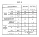
- FIG. 2 is a view illustrating a variation example of the amount of hydrogen generated when a gas composition is switched in the first exemplary embodiment of the invention.
- the flow rate of the hydrogen-containing gas decreases to approximately 85%.
- the gas composed of 20% nitrogen/80% methane, which is the relatively low heat amount gas contains a large amount of inert gas in comparison to a gas composed of 100% methane which is the relatively high heat amount gas.
- a flow rate of the raw material which does not contribute to hydrogen generation, increases in the flow rate of the raw material gas, and thus it is possible to detect a variation in the amount of the hydrogen-containing gas generated in a more remarkable manner.
- hydrogen-containing gas flow meter 3a is used as the hydrogen generation amount detection unit.
- a method capable of detecting a variation in the composition in a more reliable manner may be appropriately selected, for example, in consideration of a case where the amount of hydrogen-containing gas generated decreases by a predetermined value in a predetermined time or a case where the amount of the hydrogen-containing gas generated decreases to a predetermined flow rate threshold value in a predetermined time, a variation amount under typical driving conditions, and a behavior when a gas composition varies.
- the generation amount increases in a case where the amount of the hydrogen-containing gas generated increases by a predetermined value in a predetermined time, or in a case where the amount of the hydrogen-containing gas generated increases to a predetermined flow rate threshold value in a predetermined time.
- the values may be compared with each other after obtaining an average value for the predetermined time.
- an average value of the amount of the hydrogen-containing gas generated for 10 seconds varies by 5% or greater in comparison to an average value before one minute, it is assumed that the generation amount increases.
- the amount of the hydrogen-containing gas generated may also vary due to not only the composition of the raw material gas but also various external factors such as an ambient environment temperature, a pressure of the raw material gas, and a variation with the passage of the driving time. Accordingly, when a parameter, which contributes to the amount of the hydrogen-containing gas generated, is in a predetermined range, the setting may be changed. In addition, when a variation amount of the parameter, which contributes to the amount of the hydrogen-containing gas generated, per predetermined time is in a predetermined range, the setting may be changed.
- FIG. 3 is a view illustrating a changed image of a control parameter when an external factor is in a predetermined range in the first exemplary embodiment of the invention.
- an environment temperature is exemplified as a parameter that contributes to the amount of the hydrogen-containing gas generated.
- controller 4 performs driving by setting a control parameter corresponding to the relatively low heat amount gas.
- controller 4 performs driving by setting a control parameter corresponding to the relatively high heat amount gas.
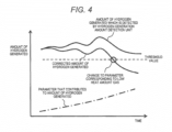
- FIG. 4 is a view illustrating a corrected image of the amount of the hydrogen-containing gas generated in the first exemplary embodiment of the invention.
- the above-described external factor may vary continuously. For example, in a case where the environment temperature continuously rises under a predetermined condition, a conversion ratio in reforming unit 1 may be raised, and thus the amount of hydrogen generated may increase. Accordingly, after correcting the amount of hydrogen generated which varies due to the external factor, whether or not a variation occurs in the amount of the hydrogen-containing gas generated, which is detected by the hydrogen generation amount detection unit, may be determined. In addition, even when correcting a threshold value for changing of the control parameter, the same effect can be obtained.
- Controller 4 performs driving by setting a control parameter corresponding to the relatively low heat amount gas in a case where the amount of the hydrogen-containing gas generated decreases, and performs driving by setting a control parameter corresponding to the relatively high heat amount gas in a case where the amount of the hydrogen-containing gas generated increases.
- control parameter for example, a control parameter such as the amount of the raw material gas supplied, the amount of water supplied (or S/C), and the flow rate of the combustion air (or a combustion air ratio), which are caused by the composition of the raw material gas, may be set.
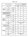
- FIG. 5 is a view illustrating a setting example of a control parameter in the first exemplary embodiment of the invention.
- a case of 100% methane is assumed as a raw material composition of the control parameter corresponding to the relatively high heat amount gas
- a case of 20% nitrogen/80% methane is assumed as a raw material composition of the control parameter corresponding to the relatively low heat amount gas.
- the amount of the raw material gas supplied is directly correlated with the amount of hydrogen that is generated.
- the setting may be performed in such a manner that the lower the amount of heat of the raw material gas supplied is, the further the amount of the raw material gas supplied increases. More specifically, in a case where the amount of the hydrogen-containing gas generated, which is detected by the hydrogen generation amount detection unit, decreases, driving may be performed by relatively increasing the flow rate of the raw material gas, and in a case where the amount of the hydrogen-containing gas generated increases, driving may be performed by relatively decreasing the flow rate of the raw material gas.
- the number of moles of a carbon number in one mole of raw material gas is 1.0.
- the number of moles of the carbon number in one mole of raw material gas becomes 0.8. That is, in a case of the same flow rate of the raw material gas and the same amount of water supplied, the value of S/C becomes 1.25 times.
- the setting may be performed in such a manner that the lower the amount of heat of the raw material gas supplied is, the further the amount of water supplied decreases.
- the setting may be performed in consideration of the composition and the flow rate of the raw material gas so as to constantly maintain S/C.
- FIG. 6 is a view illustrating an example of the relationship between a combustion air ratio and a carbon monoxide discharge concentration in the first exemplary embodiment of the invention.
- the raw material composition is 100% methane that is the relatively high heat amount gas
- a flow rate of a gas to be combusted is greater in comparison to a case of 20% nitrogen/80% methane which is the relatively low heat amount gas.
- the combustion air ratio that is, a ratio of the flow rate of the supply air to the flow rate of the combustion air which is necessary for complete combustion relatively increases, and thus it is difficult to maintain the appropriate combustion due to occurrence of carbon monoxide, and the like.
- the setting may be performed in such a manner that the lower the amount of heat of the raw material gas supplied is, the further the flow rate of the combustion air decreases.
- the setting may be performed in consideration of the composition and the flow rate of the raw material gas so as to constantly maintain the combustion air ratio.
- a control parameter which is caused by the raw material gas composition, may be appropriately set so as to efficiently and stably drive the hydrogen generation apparatus without limitation to the flow rate of the raw material, the amount of water supplied, and the flow rate of the combustion air.
- a control parameter including at least any one among the parameters may be set.
- the control parameters are changed in a composite manner, more stable driving is possible, and thus a more significant effect is obtained.
- driving in a case where the amount of the hydrogen-containing gas generated decreases, driving can be performed by setting a control parameter corresponding to the relatively low heat amount gas, and in a case where the amount of the hydrogen-containing gas generated increases, driving can be performed by setting a control parameter corresponding to the relatively high heat amount gas.
- the control parameter corresponding to the amount of heat of the raw material gas that is, the composition thereof
- the amount of the hydrogen generated is appropriately maintained, and thus it is possible to realize the hydrogen generation apparatus capable of being stably driven in an efficient manner.
- three kinds of control parameters in which a corresponding amount of heat is different, are provided as the raw material gas.
- a gas composed of 20% propane/80% methane is set as a composition of the relatively high heat amount raw material gas, a gas composed of 100% methane is set as a relatively intermediate heat amount gas, and a case of 20% nitrogen/80% methane is set as a relatively low heat amount gas.
- FIG. 7 is a view illustrating a setting example of three or more kinds of control parameters in Modification Example 1 of hydrogen generation apparatus 50 in the first exemplary embodiment.
- controller 4 performs driving by setting a control parameter corresponding to the relatively low heat amount gas.
- the composition of the raw material gas is switched from 100% methane to a gas composed of, for example, 20% nitrogen/80% methane.
- the methane gas which contains 20% nitrogen, is a relatively low heat amount gas in comparison to the case of 100% methane.
- a temperature of reforming unit 1 does not rapidly vary due to heat capacity thereof, and thus it can be considered that a conversion ratio of hydrocarbon is the same before and after conversion of gas species. That is, when the flow rate of the raw material gas and the conversion ratio are the same in each case, the amount of hydrogen generated decreases.
- the composition of the raw material gas is switched from 100% methane to a gas composed of, for example, 20% propane/80% methane.
- the methane gas which contains 20% propane, is a relatively high heat amount gas in comparison to 100% methane.
- propane the number of hydrogen atoms in one molecule is great, and thus when the flow rate of the raw material and the conversion ratio are the same in each case, the amount of hydrogen generated increases.
- hydrogen-containing gas flow meter 3a is used as a unit that detects the amount of hydrogen generated, and detection is performed by the same method as in the first exemplary embodiment.
- controller 4 performs driving by setting a control parameter (here, 20% nitrogen/80% methane) corresponding to the relatively low heat amount gas, and when the amount of the hydrogen-containing gas generated increases, controller 4 performs driving by setting a control parameter (here, 20% propane/80% methane) corresponding to the relatively high heat amount gas.
- a control parameter here, 20% nitrogen/80% methane
- control parameter to be selected may be selected in accordance with the degree of a variation in the flow rate of the hydrogen-containing gas which is detected by the hydrogen generation amount detection unit.
- controller 4 performs driving by setting a control parameter (here, 100% methane) corresponding to an intermediate amount of heat as a relatively low amount of heat, among the three control parameters.
- controller 4 performs driving by setting a control parameter (here, 20% nitrogen/80% methane) corresponding to the relatively lowest amount of heat among the three parameters.
- Modification Example 1 it is assumed that the three kinds of control parameters are provided, but a plurality of (three or more kinds of) control parameters may be provided, and these parameters may be set to be appropriately selected.
- a configuration, in which the control parameter is applied by the function on the composition of the raw material gas, that is, the amount of heat is employed as a method of setting the control parameter.
- the setting may be performed in such a manner that as the amount of heat of a raw material gas is relatively lower, for example, the flow rate of the raw material gas is set to be greater, the amount of water supplied is set to be smaller, and the flow rate of the combustion air is set to be smaller.
- the control parameter is applied as a function with respect to the amount of heat of the raw material gas which is calculated from the flow rate, which is detected by the hydrogen generation amount detection unit, of the hydrogen-containing gas.
- the raw material gas may be increased by 25% (100 ⁇ 80-1) ⁇ 100) so as to maintain the amount of hydrogen generated to be equal to that before a variation in the gas composition.
- a decrease rate can be set as a flow rate of the hydrogen-containing gas which decreases for a predetermined time.
- the decrease rate is defined as a decrease rate for one minute.
- control parameters such as the amount of water supplied and the flow rate of the combustion air, which are caused by the composition of the raw material gas, may be appropriately set by a function.
- FIG. 8 is a view illustrating a schematic configuration of hydrogen generation apparatus 60 according to the second exemplary embodiment.
- This exemplary embodiment relates to a configuration including selective oxidation unit 11 that selectively oxides and removes carbon monoxide contained in a hydrogen-containing gas by using oxygen, selective oxidation air supply device 12 that supplies selective oxidation air to selective oxidation unit 11, and selective oxidation air flow rate detector 13 that detects a flow rate of the selective oxidation air.
- Selective oxidation unit 11 has a configuration in which a predetermined temperature (here, approximately 160°C) is maintained by using an Ru-based catalyst, and oxygen-containing air is supplied from selective oxidation air supply device 12 to selectively remove carbon monoxide contained in the hydrogen-containing gas.
- a predetermined temperature here, approximately 160°C
- oxygen-containing air is supplied from selective oxidation air supply device 12 to selectively remove carbon monoxide contained in the hydrogen-containing gas.
- the hydrogen-containing gas which is obtained in reforming unit 1 and contains carbon monoxide, may be supplied to selective oxidation unit 11 after reducing carbon monoxide step by step through a converting catalyst.
- the following configuration is employed. Specifically, air is pumped by using an air pump as selective oxidation air supply device 12, and the amount of supply is measured by using a flow meter as selective oxidation air flow rate detector 13. In addition, in this exemplary embodiment, air is supplied so that a flow rate of the selective oxidation air becomes 0.7 NLM.
- selective oxidation air flow rate detector 13 that detects the flow rate of the selective oxidation air is used as the hydrogen generation amount detection unit.
- controller 4 is configured to perform driving by setting a control parameter corresponding to the relatively low heat amount gas in a case where the flow rate of the selective oxidation air increases, and is configured to perform driving by setting a control parameter corresponding to the relatively high heat amount gas in a case where the flow rate of the selective oxidation air decreases.
- controller 4 drives hydrogen generation apparatus 60 after switching to the control parameter for a low heat amount gas.
- controller 4 is configured to drive hydrogen generation apparatus 60 after switching to the control parameter for the high heat amount gas.
- the selective oxidation air is supplied to selective oxidation unit 11, and is supplied or discharged through a path of the hydrogen-containing gas after reaction.
- the amount of the hydrogen-containing gas generated decreases, the amount of a fluid, which passes through the same path, decreases. According to this, a pressure loss of the path decreases.
- the flow rate decreases to approximately 85%.
- the pressure loss of the fluid that flows through a pipeline and the like is proportional to a square of a flow speed. That is, if the cross-sectional area of a flow path is the same, the pressure loss decreases to 0.85 ⁇ 0.85, that is, approximately 72%.
- the same method as in the first exemplary embodiment can be used for the setting of the control parameter.
- selective oxidation air supply device 12 which supplies selective oxidation air to selective oxidation unit 11, is used as the hydrogen generation amount detection unit.
- air is supplied so that the flow rate of the selective oxidation air becomes 0.7 NLM, and an output of selective oxidation air supply device 12 at this time is 50%.
- controller 4 is configured to perform driving by setting a control parameter corresponding to the relatively low heat amount gas in a case where the output of selective oxidation air supply device 12 decreases, and is configured to perform driving by setting a control parameter corresponding to the relatively high heat amount gas in a case where the output of selective oxidation air supply device 12 increases.
- controller 4 drives hydrogen generation apparatus 60 after switching to a control parameter for a low heat amount gas.
- controller 4 is configured to drive hydrogen generation apparatus 60 after switching to the control parameter for the high heat amount gas.
- the variation in the flow rate of the selective oxidation air, and the variation in the output of selective oxidation air supply device 12 may be simultaneously detected.
- FIG. 9 is a view illustrating comparison of a variation in a flow rate of the selective oxidation air, a variation in an output of the selective oxidation air supply device 12, and a variation in the temperature of a reforming unit 1 when gas species are switched (here, from a high heat amount gas to a low heat amount gas) in the modification example of the second exemplary embodiment.
- FIG. 10 is a view illustrating a schematic configuration of hydrogen generation apparatus 70 according to the third exemplary embodiment.
- This exemplary embodiment relates to a configuration including pressure detector 14, which detects a pressure of a path including reforming unit 1 downstream of raw material supply device 2, as the hydrogen generation amount detection unit.
- pressure detector 14 is installed at an inlet of reforming unit 1, and a pressure measured during driving is 3.0 kPa. Furthermore, an installation position of pressure detector 14 is not limited to the example as long as a pressure caused by the amount of the hydrogen-containing gas generated can be detected at the position, and hydrogen generation apparatus 70 may have a configuration in which a pressure of an inlet portion of the raw material gas or an outlet of reforming unit 1 is detected.
- Controller 4 is configured to perform driving by setting a control parameter corresponding to the relatively low heat amount gas in a case where the pressure of pressure detector 14 decreases, and is configured to perform driving by setting a control parameter corresponding to the relatively high heat amount gas in a case where the pressure of pressure detector 14 increases.
- controller 4 drives hydrogen generation apparatus 70 after switching to a control parameter for low heat amount gas.
- controller 4 drives hydrogen generation apparatus 70 after switching to the control parameter for the high heat amount gas.
- control parameter corresponding to three or more gas species
- an appropriate control parameter may be selected, or a continuous parameter may be set as function of the amount of heat.
- This exemplary embodiment may have the same configuration as in the first exemplary embodiment illustrated in FIG. 1 , and detailed description thereof will be omitted.
- Controller 4 controls raw material supply device 2 so that the flow rate of the raw material becomes a predetermined flow rate, is configured to perform driving by setting a control parameter corresponding to the relatively low heat amount gas in a case where the output of raw material supply device 2 decreases, and is configured to perform driving by setting a control parameter corresponding to the relatively high heat amount gas in a case where the output of raw material supply device 2 increases.
- the output of raw material supply device 2 is set to 70%.
- controller 4 drives the hydrogen generation apparatus after switching to a control parameter for a low heat amount gas.
- controller 4 drives the hydrogen generation apparatus after switching to the control parameter for the high heat amount gas.
- control parameters corresponding to three or more gas species may be provided, an appropriate control parameter may be selected, or a continuous parameter may be set as function of the amount of heat.
- FIG. 11 is a view illustrating a schematic configuration of fuel cell system 80 according to the invention.
- This exemplary embodiment relates to a configuration including fuel cell 20 that performs power generation by using the hydrogen-containing gas that is supplied from hydrogen generation apparatus 50.
- an anode flow meter 3b which detects a flow rate of an anode inlet of fuel cell 20, is provided as the hydrogen generation amount detection unit.
- a polymer electrolyte fuel cell (PEFC) is used as fuel cell 20.
- PEFC polymer electrolyte fuel cell
- fuel cell 20 typically, a voltage decreases due to carbon monoxide, and thus it is necessary to reduce carbon monoxide to approximately 10 ppm or less in selective oxidation unit 11.
- the hydrogen-containing gas which is obtained in reforming unit 1 and contains carbon monoxide, may be supplied to selective oxidation unit 11 after reducing carbon monoxide step by step through a converting catalyst.
- Controller 4 supplies the hydrogen-containing gas to an anode of fuel cell 20 as a fuel gas of fuel cell 20.
- fuel cell 20 the fuel gas supplied to the anode and power generation air supplied to a cathode electrochemically react with each other to generate electricity, heat, and water.
- Electricity that is obtained in fuel cell 20 is supplied to a power load (not illustrated) and is used therein.
- heat which is generated in accordance with power generation, is recovered by a heat recovery unit (not illustrated), and is supplied to thermal load for various uses.
- an unreacted fuel gas hereinafter, referred to as "off-gas"
- off-gas an unreacted fuel gas
- Controller 4 controls combustion air supply device 7 to supply combustion air necessary for combustion of the off-gas that is supplied to combustor 6.
- the off-gas and the combustion air supplied from combustion air supply device 7 are mixed with each other, and the resultant mixed gas is combusted. According to this, heat necessary for a steam reforming reaction in reforming unit 1 is supplied.
- a flow rate of the combustion air is controlled in such a manner that an air ratio, which represents a ratio of a flow rate of supply air to a theoretical air flow rate of the combustion air, becomes 1.7.
- controller 4 calculates the amount of hydrogen generated from a hydrocarbon conversion rate calculated from a flow rate of the raw material which is detected by raw material flow rate detector 8, and a temperature detected by a reforming temperature detector (not illustrated), and issues an instruction for the amount of power generation in fuel cell 20 so that power generation can be performed in a predetermined hydrogen utilization range.
- the hydrogen utilization may be set to approximately 70% to 85% for stable driving.
- anode flow meter 3b is provided in an anode path as the hydrogen generation amount detection unit.
- a method capable of detecting a variation in the composition in a more reliable manner may be appropriately selected, for example, in consideration of a case where the amount of hydrogen-containing gas generated decreases by a predetermined value in a predetermined time or a case where the amount of the hydrogen-containing gas generated decreases to a predetermined flow rate threshold value in a predetermined time, a variation amount under typical driving conditions, and a behavior when a gas composition varies.
- the generation amount increases in a case where the amount of the hydrogen-containing gas generated increases by a predetermined value in a predetermined time, or in a case where the amount of the hydrogen-containing gas generated increases to a predetermined flow rate threshold value in a predetermined time.
- the values may be compared with each other after obtaining an average value for the predetermined time.
- a method of directly detecting the amount of the hydrogen-containing gas generated by using anode flow meter 3b is used.
- a variation in the composition of the raw material gas may be detected by detecting a variation in a pressure loss by using a pressure detector, or by indirectly detecting a variation in a pressure, which is caused by a variation in a flow rate of the anode path, by using the flow rate of the selective oxidation flow meter, the output of selective oxidation air supply device 12, the output of raw material supply device 2, and the like.
- the amount of hydrogen generated varies in accordance with a desired power generation output in fuel cell 20. Accordingly, when the output of fuel cell 20 is in a predetermined range, the setting may be changed. In addition, if the amount of variation per predetermined time in the output of fuel cell 20 is in a predetermined range, the setting may be changed. On the other hand, a generated power may be changed, for example, in accordance with a load.
- Controller 4 may correct the amount of the hydrogen-containing gas generated, which is detected by the hydrogen generation amount detection unit, on the basis of the output of fuel cell 20. In addition, even when correcting a threshold value for changing of the control parameter, the same effect is obtained.
- FIG. 12 is a view illustrating a corrected image of the amount of the hydrogen-containing gas generated in accordance with a variation in an output of fuel cell 20 in the invention.
- control of increasing the flow rate of the raw material is performed on the basis of a variation in the amount of power generation.
- the amount of hydrogen generated also increases in accordance with an increase in the flow rate of the raw material.
- a variation in the amount of hydrogen generated which is greater than an amount appropriate for an increase in the flow rate of the raw material, occurs, a variation in the composition of the raw material gas can be detected.
- a parameter relating to driving of fuel cell 20 is set in addition to a parameter of hydrogen generation apparatus 50 in the first exemplary embodiment.
- a flow rate of a gas to be combusted in combustor 6 decreases in accordance with a decrease in the amount of hydrogen. That is, in a case where a flow rate of the combustion air is the same, there is a possibility that the flow rate of the combustion air may be excessive with respect to the flow rate of the gas to be combusted.
- a combustion air ratio becomes excessive, it is difficult to maintain appropriate combustion, and thus there is a possibility that carbon monoxide may occur.
- the flow rate of the gas to be combusted in combustor 6 increases in accordance with an increase in the amount of hydrogen. That is, in a case where the flow rate of the combustion air is the same, there is a possibility that the flow rate of the combustion air may be excessively small with respect to the flow rate of the gas to be combusted. When the combustion air ratio becomes excessively small, it is difficult to maintain appropriate combustion, and thus there is a possibility that carbon monoxide may occur.
- driving may be performed by decreasing the amount of power generation in fuel cell 20.
- the amount of hydrogen generated increases, the amount of power generation in fuel cell 20 may be increased.
- driving is performed at 750 W by using a parameter corresponding to a high heat amount
- control is performed to decrease the amount of power generation to 600 W.
- the amount of power generation may be returned to the original value after changing a parameter (for example, the flow rate of the raw material gas) other than the amount of power generation to a parameter corresponding to a low heat amount, that is, after the amount of hydrogen generated becomes an appropriate amount. According to this configuration, it is possible to perform stable driving with an appropriate amount of power generation.
- a parameter for example, the flow rate of the raw material gas
- the amount of hydrogen generated increases on the basis of an input from an outer side, for example, in a case of fuel cell 20, a command of increasing the power generation output.
- the control parameter may be set by determining whether or not the amount of the hydrogen-containing gas generated, which is detected by the hydrogen generation amount detection unit, varies.
- control parameters corresponding to three or more gas species may be provided, an appropriate control parameter may be selected, or a continuous parameter may be set as function of the amount of heat.
- FIG. 13 is a view illustrating a schematic configuration of fuel cell system 80 in Modification Example 1 of the invention.
- This modification example relates to a configuration including cathode air supply device 21 that supplies air to a cathode of fuel cell 20.
- cathode air supply device 21 is configured to be controlled so that selective oxidation air is supplied to selective oxidation unit 11 after diverging from a cathode air supply path of fuel cell 20, and a flow rate, which is detected by selective oxidation air flow rate detector 13, becomes a predetermined flow rate.
- an air blower is used as cathode air supply device 21, an air blower is used as cathode air supply device 21, as cathode air supply device 21, an air blower is used.
- the hydrogen generation amount detection unit detects a variation in a pressure which is caused by a variation in a flow rate of the anode path of fuel cell 20. Specifically, a variation in the pressure is detected from a variation in the output of cathode air supply device 21, a variation in the flow rate of the selective oxidation air, or a variation in the anode air flow rate.
- controller 4 performs driving by setting a control parameter corresponding to the relatively low heat amount gas.
- controller 4 performs driving by setting a control parameter corresponding to the relatively high heat amount gas.
- control parameters corresponding to three or more gas species may be provided, an appropriate control parameter may be selected, or a continuous parameter may be set as function of the amount of heat.
- FIG. 14 is a view illustrating a schematic configuration of fuel cell system 80 in Modification Example 2 of the invention.
- This modification example relates to a configuration including off-gas flow meter 3c as the hydrogen generation amount detection unit in an off-gas path on an outlet of the anode of fuel cell 20 as the hydrogen generation amount detection unit.
- FIG. 15 is a view illustrating a variation in a flow rate of an off-gas in a case where a power generation output of fuel cell 20, that is, a current value and the amount of hydrogen consumed are the same between a case where a gas composed of 100% methane is supplied and a case where a gas composed of 20% nitrogen/80% methane is supplied in Modification Example 2 of the invention.$
- the flow rate of the off-gas decreases to approximately 61%.
- a pressure loss of a flow path decreases to approximately 37% by 0.61 ⁇ 0.61. That is, as illustrated in FIG. 15 , in a case where an inert gas and a gas composed of 20% nitrogen/80% methane, which is the relatively low heat amount gas are supplied, the amount of hydrogen generated decreases.
- the flow rate of the off-gas in fuel cell 20 and a pressure loss of the path caused by the flow rate significantly decrease.
- the flow rate of the off-gas is directly detected by using off-gas flow meter 3c.
- a variation in the composition of the raw material gas may be detected, for example, by detecting a variation in the pressure, or by indirectly detecting a variation in the pressure, which is caused by a variation in the flow rate of the off-gas path, by using the flow rate of the selective oxidation flow meter, the output of selective oxidation air supply device 12, the output of raw material supply device 2, and the like.
- control parameters corresponding to three or more gas species may be provided, an appropriate control parameter may be selected, or a continuous parameter may be set as function of the amount of heat.
- this configuration it is possible more instantly and reliably to detect a variation in the amount of the hydrogen-containing gas generated, which is caused by a variation in the composition of the raw material gas, by detecting a variation in the flow rate of the off-gas path or a variation in the pressure which is caused by a variation in the flow rate. According to this, it is possible to perform power generation suitable for the amount of heat of the raw material gas, and thus it is possible to realize a fuel cell system that can be more stably driven. In addition, it is possible to maintain stable combustion in which occurrence of carbon monoxide is suppressed.
- the hydrogen generation apparatus further includes a selective oxidation unit that selectively oxidizes and removes carbon monoxide contained in the hydrogen-containing gas by using oxygen, a selective oxidation air supply device that supplies selective oxidation air to the selective oxidation unit, a selective oxidation air flow rate detector that detects a flow rate of the selective oxidation air.
- the hydrogen generation amount detection unit is a selective oxidation air flow rate detector, and the controller is configured to drive the raw material supply device by setting a control parameter corresponding to the relatively low heat amount gas in a case where a flow rate of the selective oxidation air increases, and is configured to drive the raw material supply device by setting a control parameter corresponding to the relatively high heat amount gas in a case where the flow rate of the selective oxidation air decreases.
- the hydrogen generation apparatus further includes a selective oxidation unit that selectively oxidizes and removes carbon monoxide contained in the hydrogen-containing gas by using oxygen, a selective oxidation air supply device that supplies selective oxidation air to the selective oxidation unit, and a selective oxidation air flow rate detector that detects a flow rate of the selective oxidation air.
- the controller controls the selective oxidation air supply device so that a flow rate of the selective oxidation air becomes a predetermined flow rate, and is configured to drive the raw material supply device by setting a control parameter corresponding to the relatively low heat amount gas in a case where an output of the selective oxidation air supply device decreases, and is configured to drive the raw material supply device by setting a control parameter corresponding to the relatively high heat amount gas in a case where the output of the selective oxidation air supply device increases.
- the hydrogen generation apparatus further includes a pressure detector that detects a pressure of a path including the reforming unit downstream of the raw material supply device.
- the hydrogen generation amount detection unit is the pressure detector, and the controller configured to drive the raw material supply device by setting a control parameter corresponding to the relatively low heat amount gas in a case where the pressure of the pressure detector decreases, and is configured to drive the raw material supply device by setting a control parameter corresponding to the relatively high heat amount gas in a case where the pressure of the pressure detector increases.
- the hydrogen generation apparatus further includes a raw material flow rate detector that detects a flow rate of the raw material.
- the controller controls the raw material supply device so that the flow rate of the raw material becomes a predetermined flow rate, and is configured to drive the raw material supply device by setting a control parameter corresponding to the relatively low heat amount gas in a case where an output of the raw material supply device decreases, and is configured to drive the raw material supply device by setting a control parameter corresponding to the relatively high heat amount gas in a case where the output of the raw material supply device increases.
- the low heat amount gas contains a large amount of inert gas in comparison to the high heat amount gas.
- the controller when a parameter that contributes to the amount of the hydrogen-containing gas generated is in a predetermined range, the controller is configured to drive the raw material supply device by setting a control parameter corresponding to the relatively low heat amount gas in a case where the amount of the hydrogen-containing gas generated decreases, and is configured to drive the raw material supply device by setting a control parameter corresponding to the relatively high heat amount gas in a case where the amount of the hydrogen-containing gas generated increases.
- the controller when the amount of variation in a parameter that contributes to the amount of the hydrogen-containing gas generated is in a predetermined range, is configured to drive the raw material supply device by setting a control parameter corresponding to the relatively low heat amount gas in a case where the amount of the hydrogen-containing gas generated decreases, and is configured to drive the raw material supply device by setting a control parameter corresponding to the relatively high heat amount gas in a case where the amount of the hydrogen-containing gas generated increases.
- the controller is configured to correct the amount of the hydrogen-containing gas generated, which is detected by the hydrogen generation amount detection unit, on the basis of a parameter that contributes to the amount of the hydrogen-containing gas generated.
- the controller is configured to drive the combustion air supply device by setting a control parameter corresponding to the relatively low heat amount gas in a case where the amount of the hydrogen-containing gas generated decreases, and is configured to drive the combustion air supply device by setting a control parameter corresponding to the relatively high heat amount gas in a case where the amount of the hydrogen-containing gas generated increases.
- the amount of the hydrogen-containing gas generated varies in accordance with a variation in the composition of the raw material gas, and thus it is possible to instantly detect the variation in the composition of the raw material gas by detecting the variation in the amount of the hydrogen-containing gas generated.
- a control parameter of the combustion air supply device which corresponds to the composition of the raw material gas, is set on the basis of the resultant detection result, the amount of hydrogen generated is appropriately maintained, and thus it is possible to realize a hydrogen generation apparatus capable of being stably driven.
- the controller is configured to correct the amount of the hydrogen-containing gas generated, which is detected by the hydrogen generation amount detection unit, on the basis of the output of the fuel cell.
- the controller is configured to drive the water supply device by setting a control parameter corresponding to the relatively low heat amount gas in a case where the amount of the hydrogen-containing gas generated decreases, and is configured to drive the water supply device by setting a control parameter corresponding to the relatively high heat amount gas in a case where the amount of the hydrogen-containing gas generated increases.
- the amount of the hydrogen-containing gas generated varies in accordance with a variation in the composition of the raw material gas, and thus it is possible to instantly detect the variation in the composition of the raw material gas by detecting the variation in the amount of the hydrogen-containing gas generated.
- a control parameter of the water supply device which corresponds to the composition of the raw material gas, is set on the basis of the resultant detection result, the amount of hydrogen generated is appropriately maintained, and thus it is possible to realize a hydrogen generation apparatus capable of being stably driven.
- the controller is configured to drive the combustion air supply device by setting a control parameter corresponding to the relatively low heat amount gas in a case where the amount of the hydrogen-containing gas generated decreases, and is configured to drive the combustion air supply device by setting a control parameter corresponding to the relatively high heat amount gas in a case where the amount of the hydrogen-containing gas generated increases.
- the amount of the hydrogen-containing gas generated varies in accordance with a variation in the composition of the raw material gas, and thus it is possible to instantly detect the variation in the composition of the raw material gas by detecting the variation in the amount of the hydrogen-containing gas generated.
- a control parameter of the combustion air supply device which corresponds to the composition of the raw material gas, is set on the basis of the resultant detection result, the amount of hydrogen generated is appropriately maintained, and thus it is possible to realize a hydrogen generation apparatus capable of being stably driven.
- the driving method even when the composition of the raw material gas that is supplied varies during driving of the hydrogen generation apparatus, it is possible to instantly detect a variation in the composition of the raw material gas by detecting the variation in the amount of the hydrogen-containing gas generated.
- a control parameter corresponding to the composition of the raw material gas is set on the basis of the resultant detection result, the amount of hydrogen generated is appropriately maintained, and thus it is possible to realize a method of driving a hydrogen generation apparatus capable of being stably driven.
- the composition of the raw material gas that is, the amount of heat varies during driving
- a variation in the composition of the raw material gas is instantly detected by instantly detecting a variation in the amount of the hydrogen-containing gas generated, and an appropriate parameter is set. According to this, it is possible to exhibit a remarkable effect in which stable driving is possible.
- the invention is particularly useful for a case where the composition of the raw material gas may vary with the passage of time, and is useful for a hydrogen generation apparatus that reforms a hydrocarbon-containing raw material gas such as a dispersive solid polymer type and a solid oxide type to generate hydrogen, a driving method thereof, a fuel cell system including a fuel cell that performs power generation by using the hydrogen-containing gas that is obtained in the hydrogen generation apparatus, and the like.
- a hydrogen generation apparatus that reforms a hydrocarbon-containing raw material gas such as a dispersive solid polymer type and a solid oxide type to generate hydrogen
- a driving method thereof a fuel cell system including a fuel cell that performs power generation by using the hydrogen-containing gas that is obtained in the hydrogen generation apparatus, and the like.
Landscapes
- Chemical & Material Sciences (AREA)
- Chemical Kinetics & Catalysis (AREA)
- Engineering & Computer Science (AREA)
- Organic Chemistry (AREA)
- General Chemical & Material Sciences (AREA)
- Sustainable Energy (AREA)
- Sustainable Development (AREA)
- Electrochemistry (AREA)
- Life Sciences & Earth Sciences (AREA)
- Materials Engineering (AREA)
- Manufacturing & Machinery (AREA)
- Health & Medical Sciences (AREA)
- General Health & Medical Sciences (AREA)
- Combustion & Propulsion (AREA)
- Inorganic Chemistry (AREA)
- Hydrogen, Water And Hydrids (AREA)
- Fuel Cell (AREA)
Claims (10)
- Brennstoffzellensystem, umfassend:eine Wasserstofferzeugungsvorrichtung (50, 60, 70); undeine Brennstoffzelle (20),wobei die Wasserstofferzeugungsvorrichtung (50, 60, 70) umfasst:eine Reformiereinheit (1), die einen Rohstoff reformiert, um ein wasserstoffhaltiges Gas zu erzeugen, das der Brennstoffzelle (20) als Brenngas zugeführt wird;eine Rohstoffzufuhrvorrichtung (2), die den Rohstoff der Reformiereinheit (1) zuführt; undeine Wasserzufuhrvorrichtung (5), die der Reformiereinheit (1) Wasser zuführt; und eine Brennkammer (6), die den Rohstoff oder den Teil des Brenngases verbrennt, der nicht in der Brennstoffzelle (20) verbraucht wird;eine Verbrennungsluftzufuhrvorrichtung (7), die der Brennkammer (6) Verbrennungsluft zuführt; undeine Wasserstofferzeugungsmengen-Erfassungseinheit (3a, 13, 14, 8), die eine Menge des erzeugten wasserstoffhaltigen Gases erfasst; undeine Steuerung (4); undwobei die Brennstoffzelle (20) unter Verwendung des wasserstoffhaltigen Gases, das von der Wasserstofferzeugungsvorrichtung (50, 60, 70) zugeführt wird, eine Stromerzeugung durchführt,dadurch gekennzeichnet, dasswenn ein Parameter, der zu der Menge des erzeugten wasserstoffhaltigen Gases beiträgt, in einem vorgegebenen Bereich liegt, oder wenn eine Mengenänderung eines Parameters, der zu der Menge des erzeugten wasserstoffhaltigen Gases beiträgt, in einem vorgegebenen Bereich liegt, die Steuerung (4) dazu konfiguriert ist, die Rohstoffzufuhrvorrichtung (2) durch Einstellen eines Steuerparameters anzusteuern, der Gas mit einer relativ niedrigen Wärmemenge entspricht, wenn die Menge des erzeugten wasserstoffhaltigen Gases abnimmt, und dazu konfiguriert ist, die Rohstoffzufuhrvorrichtung (2) durch Einstellen eines Steuerparameters anzusteuern, der Gas mit einer relativ hohen Wärmemenge entspricht, wenn die Menge des erzeugten wasserstoffhaltigen Gases zunimmt,wobei der Steuerparameter eines aus einer Menge des zugeführten Rohstoffs, einer Menge des zugeführten Wassers und einer Durchflussrate der Verbrennungsluft ist, undwobei der Parameter mindestens eines aus einer Zusammensetzung des Rohstoffs, einer Umgebungstemperatur und einem Druck des Rohstoffs ist.
- Brennstoffzellensystem nach Anspruch 1, wobei die Wasserstofferzeugungsvorrichtung des Weiteren umfasst:eine selektive Oxidationseinheit (11), die in dem wasserstoffhaltigen Gas enthaltenes Kohlenmonoxid unter Verwendung von Sauerstoff selektiv oxidiert und entfernt;eine Zufuhrvorrichtung (12) für selektive Oxidationsluft, die der selektiven Oxidationseinheit (11) selektive Oxidationsluft zuführt; undeinen Durchflussratendetektor (13) für die selektive Oxidationsluft, der eine Durchflussrate der selektiven Oxidationsluft erfasst,wobei die Wasserstofferzeugungsmengen-Erfassungseinheit der Durchflussratendetektor (13) für die selektive Oxidationsluft (13) ist, unddie Steuerung (4) dazu konfiguriert ist, die Rohstoffzufuhrvorrichtung (2) durch Einstellen des Steuerparameters, der dem Gas mit relativ geringer Wärmemenge entspricht, in einem Fall anzusteuern, in dem eine Durchflussrate der selektiven Oxidationsluft zunimmt, und dazu konfiguriert ist, die Rohstoffzufuhrvorrichtung durch Einstellen des Steuerparameters, der dem Gas mit relativ hoher Wärmemenge entspricht, in einem Fall anzusteuern, in dem die Durchflussrate der selektiven Oxidationsluft abnimmt.
- Brennstoffzellensystem nach Anspruch 1, wobei die Wasserstofferzeugungsvorrichtung des Weiteren umfasst:eine selektive Oxidationseinheit (11), die in dem wasserstoffhaltigen Gas enthaltenes Kohlenmonoxid unter Verwendung von Sauerstoff selektiv oxidiert und entfernt;eine Zufuhrvorrichtung (12) für selektive Oxidationsluft, die der selektiven Oxidationseinheit (11) selektive Oxidationsluft zuführt; undeinen Durchflussratendetektor (13) für die selektive Oxidationsluft, der eine Durchflussrate der selektiven Oxidationsluft erfasst,wobei die Steuerung (4) die Zufuhrvorrichtung (12) für selektive Oxidationsluft so steuert, dass die Durchflussrate der selektiven Oxidationsluft eine vorgegebene Durchflussrate wird, dazu konfiguriert ist, die Rohstoffzufuhrvorrichtung (2) durch Einstellen des Steuerparameters, der dem Gas mit relativ niedriger Wärmemenge entspricht, in einem Fall anzusteuern, in dem eine Ausgabe der Zufuhrvorrichtung (12) für selektive Oxidationsluft abnimmt, und dazu konfiguriert ist, die Rohstoffzufuhrvorrichtung durch Einstellen des Steuerparameters, der dem Gas mit relativ hoher Wärmemenge entspricht, in einem Fall anzusteuern, in dem die Ausgabe der Zufuhrvorrichtung (12) für selektive Oxidationsluft zunimmt.
- Brennstoffzellensystem nach Anspruch 1, wobei die Wasserstofferzeugungsvorrichtung des Weiteren umfasst:einen Druckdetektor (14), der den Druck eines Weges erfasst, der die Reformiereinheit (1) stromabwärts von der Rohstoffzufuhrvorrichtung (2) einschließt,wobei die Wasserstofferzeugungsmengen-Erfassungseinheit der Druckdetektor (14) ist,die Steuerung (4) dazu konfiguriert ist, die Rohstoffzufuhrvorrichtung (2) durch Einstellen eines Steuerparameters anzusteuern, der dem Gas mit relativ geringer Wärmemenge entspricht, wenn der von dem Druckdetektor (14) erfasste Druck abnimmt, und dazu konfiguriert ist, die Rohstoffzufuhrvorrichtung durch Einstellen eines Steuerparameters anzusteuern, der dem Gas mit relativ hoher Wärmemenge entspricht, wenn der von dem Druckdetektor (14) erfasste Druck zunimmt.
- Brennstoffzellensystem nach Anspruch 1, wobei die Wasserstofferzeugungsvorrichtung des Weiteren umfasst:einen Rohstoff-Durchflussratendetektor (8), der eine Durchflussrate des Rohstoffs erfasst,wobei die Steuerung (4) die Rohstoffzufuhrvorrichtung (2) so steuert, dass die Durchflussrate des Rohstoffs eine vorgegebene Durchflussrate wird, dazu konfiguriert ist, die Rohstoffzufuhrvorrichtung (2) durch Einstellen des Steuerparameters, der dem Gas mit relativ geringer Wärmemenge entspricht, in einem Fall anzusteuern, in dem eine Ausgabe der Rohstoffzufuhrvorrichtung (2) abnimmt, und dazu konfiguriert ist, die Rohstoffzufuhrvorrichtung (2) durch Einstellen des Steuerparameters, der dem Gas mit relativ hoher Wärmemenge entspricht, in einem Fall anzusteuern, in dem die Ausgabe der Rohstoffzufuhrvorrichtung (2) zunimmt.
- Brennstoffzellensystem nach Anspruch 1, wobei die Steuerung (4) dazu konfiguriert ist, die Menge des erzeugten wasserstoffhaltigen Gases, die von der Wasserstofferzeugungsmengen-Erfassungseinheit erfasst wird, auf der Grundlage einer Ausgabe der Brennstoffzelle (20) zu korrigieren.
- Brennstoffzellensystem nach einem der Ansprüche 1 bis 6,
wobei die Steuerung (4) dazu konfiguriert ist, die Wasserzufuhrvorrichtung (5) durch Einstellen des Steuerparameters, der dem Gas mit relativ geringer Wärmemenge entspricht, in einem Fall anzusteuern, in dem die Menge des erzeugten wasserstoffhaltigen Gases abnimmt, und dazu konfiguriert ist, die Wasserzufuhrvorrichtung (5) durch Einstellen des Steuerparameters, der dem Gas mit relativ hoher Wärmemenge entspricht, in einem Fall anzusteuern, in dem die Menge des erzeugten wasserstoffhaltigen Gases zunimmt. - Brennstoffzellensystem nach einem der Ansprüche 1 bis 7,
wobei die Steuerung (4) dazu konfiguriert ist, die Verbrennungsluftzufuhrvorrichtung (7) durch Einstellen des Steuerparameters, der dem Gas mit relativ geringer Wärmemenge entspricht, in einem Fall anzusteuern, in dem die Menge des erzeugten wasserstoffhaltigen Gases abnimmt, und dazu konfiguriert ist, die Verbrennungsluftzufuhrvorrichtung (7) durch Einstellen des Steuerparameters, der dem Gas mit relativ hoher Wärmemenge entspricht, in einem Fall anzusteuern, in dem die Menge des erzeugten wasserstoffhaltigen Gases zunimmt. - Verfahren zum Ansteuern einer Wasserstofferzeugungsvorrichtung mit einer Reformiereinheit (1), die einen Rohstoff reformiert, um ein wasserstoffhaltiges Gas zur Zuführung zu einer Brennstoffzelle (20) eines Brennstoffzellensystems als Brenngas zu erzeugen, einer Rohstoffzufuhrvorrichtung (2), die den Rohstoff der Reformiereinheit (1) zuführt, einer Wasserzufuhrvorrichtung (5), die der Reformiereinheit (1) Wasser zuführt, einer Brennkammer (6), die den Rohstoff oder einen Teil des Brenngases, der nicht in der Brennstoffzelle (20) verbraucht wird, verbrennt, und einer Verbrennungsluftzufuhrvorrichtung (7), die der Brennkammer (6) Verbrennungsluft zuführt, wobei die Brennstoffzelle (20) unter Verwendung des wasserstoffhaltigen Gases, das von der Wasserstofferzeugungsvorrichtung (50, 60, 70) zugeführt wird, eine Stromerzeugung durchführt, wobei das Verfahren dadurch gekennzeichnet ist, dass es umfasst:wenn ein Parameter, der zu der Menge des erzeugten wasserstoffhaltigen Gases beiträgt, in einem vorgegebenen Bereich liegt, oder wenn eine Mengenänderung eines Parameters, der zu der Menge des erzeugten wasserstoffhaltigen Gases beiträgt, in einem vorgegebenen Bereich liegt, einen Schritt zum Ansteuern der Rohstoffzufuhrvorrichtung (2) durch Einstellen eines Steuerparameters, der einem Gas mit relativ geringer Wärmemenge entspricht, in einem Fall, in dem eine Menge des erzeugten wasserstoffhaltigen Gases abnimmt, odereinen Schritt zum Ansteuern der Rohstoffzufuhrvorrichtung (2) durch Einstellen eines Steuerparameters, der einem Gas mit relativ hoher Wärmemenge entspricht, in einem Fall, in dem die Menge des erzeugten wasserstoffhaltigen Gases zunimmt,wobei der Steuerparameter eines aus einer Menge des zugeführten Rohstoffs, einer Menge des zugeführten Wassers und einer Durchflussrate der Verbrennungsluft ist, undwobei der Parameter mindestens eines aus einer Zusammensetzung des Rohstoffs, einer Umgebungstemperatur und einem Druck des Rohstoffs ist.
- Verfahren nach Anspruch 9, wobei das Gas mit geringer Wärmemenge im Vergleich zu dem Gas mit hoher Wärmemenge eine große Menge eines Inertgases enthält.
Applications Claiming Priority (2)
| Application Number | Priority Date | Filing Date | Title |
|---|---|---|---|
| JP2014220128 | 2014-10-29 | ||
| PCT/JP2015/005375 WO2016067589A1 (ja) | 2014-10-29 | 2015-10-27 | 水素生成装置およびその運転方法、ならびに燃料電池システム |
Publications (3)
| Publication Number | Publication Date |
|---|---|
| EP3214039A1 EP3214039A1 (de) | 2017-09-06 |
| EP3214039A4 EP3214039A4 (de) | 2017-11-08 |
| EP3214039B1 true EP3214039B1 (de) | 2025-05-07 |
Family
ID=55856955
Family Applications (1)
| Application Number | Title | Priority Date | Filing Date |
|---|---|---|---|
| EP15855017.8A Active EP3214039B1 (de) | 2014-10-29 | 2015-10-27 | Wasserstofferzeugungsvorrichtung, verfahren zum betrieb davon und brennstoffzellensystem |
Country Status (3)
| Country | Link |
|---|---|
| EP (1) | EP3214039B1 (de) |
| JP (1) | JPWO2016067589A1 (de) |
| WO (1) | WO2016067589A1 (de) |
Family Cites Families (8)
| Publication number | Priority date | Publication date | Assignee | Title |
|---|---|---|---|---|
| JP3552064B2 (ja) * | 1994-01-11 | 2004-08-11 | 新日本石油株式会社 | 水素製造装置の制御方法及びその装置 |
| JP2002179404A (ja) * | 2000-12-08 | 2002-06-26 | Toho Gas Co Ltd | 燃料改質器の運転制御システム |
| JP2006256928A (ja) * | 2005-03-18 | 2006-09-28 | Sumitomo Chemical Co Ltd | 水素製造プラントの制御システム |
| JP2009179516A (ja) * | 2008-01-30 | 2009-08-13 | Fuji Electric Holdings Co Ltd | 改質装置 |
| JP2012246170A (ja) * | 2011-05-27 | 2012-12-13 | Panasonic Corp | 水素生成装置、燃料電池システム、及び水素生成装置の運転方法 |
| EP2824067A4 (de) * | 2012-03-08 | 2015-03-18 | Panasonic Corp | Wasserstofferzeugungsvorrichtung und betriebsverfahren dafür sowie brennstoffzellensystem |
| JP2014047083A (ja) * | 2012-08-29 | 2014-03-17 | Osaka Gas Co Ltd | 水素含有ガス生成装置及び水素含有ガス生成量調節方法 |
| DE102012023438B4 (de) * | 2012-11-30 | 2015-06-03 | Robert Bosch Gmbh | Verfahren zum Betrieb eines Brennstoffzellensystems und Brennstoffzellensystem für die Durchführung des Verfahrens |
-
2015
- 2015-10-27 EP EP15855017.8A patent/EP3214039B1/de active Active
- 2015-10-27 JP JP2016556352A patent/JPWO2016067589A1/ja active Pending
- 2015-10-27 WO PCT/JP2015/005375 patent/WO2016067589A1/ja not_active Ceased
Also Published As
| Publication number | Publication date |
|---|---|
| JPWO2016067589A1 (ja) | 2017-08-10 |
| EP3214039A1 (de) | 2017-09-06 |
| WO2016067589A1 (ja) | 2016-05-06 |
| EP3214039A4 (de) | 2017-11-08 |
Similar Documents
| Publication | Publication Date | Title |
|---|---|---|
| EP2950378B1 (de) | Brennstoffzellensystem | |
| CN101379646B (zh) | 燃料电池系统 | |
| US10622646B2 (en) | Fuel cell system and shutdown method thereof | |
| EP3764446A1 (de) | Brennstoffzellensystem und verfahren zum betrieb des brennstoffzellensystems | |
| EP2541659B1 (de) | Brennstoffzellensystem und steuerverfahren dafür | |
| US9090464B2 (en) | Hydrogen generation apparatus and fuel cell system | |
| JP5289361B2 (ja) | 燃料電池システム及びその電流制御方法 | |
| US9116528B2 (en) | Hydrogen generation apparatus, fuel cell system, and method of operating the same | |
| EP2835342A1 (de) | Wasserstofferzeugungsvorrichtung und betriebsverfahren dafür sowie brennstoffzellensystem | |
| US20130316257A1 (en) | Fuel cell system | |
| JP6857846B2 (ja) | 燃料電池システムおよびその運転方法 | |
| JP2005209547A (ja) | 燃料電池発電装置及び燃料電池発電装置の運転方法 | |
| JPWO2014097622A1 (ja) | 燃料電池システムおよび燃料電池システムの運転方法 | |
| EP3214039B1 (de) | Wasserstofferzeugungsvorrichtung, verfahren zum betrieb davon und brennstoffzellensystem | |
| US9184455B2 (en) | Fuel cell system and method of operating the same | |
| JP5353214B2 (ja) | 水素生成装置、及びそれを備えた燃料電池発電システム | |
| JP2009117170A (ja) | 水素製造発電システム及びその負荷追従発電方法 | |
| JP2016132592A (ja) | 水素生成装置及び燃料電池システム | |
| JP2017027668A (ja) | 燃料電池システムとその運転方法 | |
| US20140023944A1 (en) | Fuel cell system and method of operating same | |
| JP6590271B2 (ja) | 燃料電池システム | |
| JP5592760B2 (ja) | 燃料電池発電システム | |
| JP2014001104A (ja) | 水素生成装置、燃料電池システム及びその運転方法 | |
| JP5903573B2 (ja) | 燃料電池システム | |
| JP2016162606A (ja) | 燃料電池システムとその運転方法 |
Legal Events
| Date | Code | Title | Description |
|---|---|---|---|
| STAA | Information on the status of an ep patent application or granted ep patent |
Free format text: STATUS: THE INTERNATIONAL PUBLICATION HAS BEEN MADE |
|
| PUAI | Public reference made under article 153(3) epc to a published international application that has entered the european phase |
Free format text: ORIGINAL CODE: 0009012 |
|
| STAA | Information on the status of an ep patent application or granted ep patent |
Free format text: STATUS: REQUEST FOR EXAMINATION WAS MADE |
|
| 17P | Request for examination filed |
Effective date: 20160622 |
|
| AK | Designated contracting states |
Kind code of ref document: A1 Designated state(s): AL AT BE BG CH CY CZ DE DK EE ES FI FR GB GR HR HU IE IS IT LI LT LU LV MC MK MT NL NO PL PT RO RS SE SI SK SM TR |
|
| AX | Request for extension of the european patent |
Extension state: BA ME |
|
| A4 | Supplementary search report drawn up and despatched |
Effective date: 20171010 |
|
| RIC1 | Information provided on ipc code assigned before grant |
Ipc: C01B 3/38 20060101AFI20171004BHEP Ipc: H01M 8/0612 20160101ALI20171004BHEP Ipc: B01J 23/46 20060101ALI20171004BHEP |
|
| DAV | Request for validation of the european patent (deleted) | ||
| DAX | Request for extension of the european patent (deleted) | ||
| STAA | Information on the status of an ep patent application or granted ep patent |
Free format text: STATUS: EXAMINATION IS IN PROGRESS |
|
| 17Q | First examination report despatched |
Effective date: 20190114 |
|
| GRAP | Despatch of communication of intention to grant a patent |
Free format text: ORIGINAL CODE: EPIDOSNIGR1 |
|
| STAA | Information on the status of an ep patent application or granted ep patent |
Free format text: STATUS: GRANT OF PATENT IS INTENDED |
|
| INTG | Intention to grant announced |
Effective date: 20241205 |
|
| GRAS | Grant fee paid |
Free format text: ORIGINAL CODE: EPIDOSNIGR3 |
|
| GRAA | (expected) grant |
Free format text: ORIGINAL CODE: 0009210 |
|
| STAA | Information on the status of an ep patent application or granted ep patent |
Free format text: STATUS: THE PATENT HAS BEEN GRANTED |
|
| AK | Designated contracting states |
Kind code of ref document: B1 Designated state(s): AL AT BE BG CH CY CZ DE DK EE ES FI FR GB GR HR HU IE IS IT LI LT LU LV MC MK MT NL NO PL PT RO RS SE SI SK SM TR |
|
| REG | Reference to a national code |
Ref country code: GB Ref legal event code: FG4D |
|
| REG | Reference to a national code |
Ref country code: CH Ref legal event code: EP |
|
| REG | Reference to a national code |
Ref country code: DE Ref legal event code: R096 Ref document number: 602015091611 Country of ref document: DE |
|
| REG | Reference to a national code |
Ref country code: IE Ref legal event code: FG4D |
|
| REG | Reference to a national code |
Ref country code: NL Ref legal event code: MP Effective date: 20250507 |
|
| PG25 | Lapsed in a contracting state [announced via postgrant information from national office to epo] |
Ref country code: PT Free format text: LAPSE BECAUSE OF FAILURE TO SUBMIT A TRANSLATION OF THE DESCRIPTION OR TO PAY THE FEE WITHIN THE PRESCRIBED TIME-LIMIT Effective date: 20250908 Ref country code: FI Free format text: LAPSE BECAUSE OF FAILURE TO SUBMIT A TRANSLATION OF THE DESCRIPTION OR TO PAY THE FEE WITHIN THE PRESCRIBED TIME-LIMIT Effective date: 20250507 Ref country code: ES Free format text: LAPSE BECAUSE OF FAILURE TO SUBMIT A TRANSLATION OF THE DESCRIPTION OR TO PAY THE FEE WITHIN THE PRESCRIBED TIME-LIMIT Effective date: 20250507 |
|
| REG | Reference to a national code |
Ref country code: LT Ref legal event code: MG9D |
|
| PG25 | Lapsed in a contracting state [announced via postgrant information from national office to epo] |
Ref country code: NO Free format text: LAPSE BECAUSE OF FAILURE TO SUBMIT A TRANSLATION OF THE DESCRIPTION OR TO PAY THE FEE WITHIN THE PRESCRIBED TIME-LIMIT Effective date: 20250807 Ref country code: GR Free format text: LAPSE BECAUSE OF FAILURE TO SUBMIT A TRANSLATION OF THE DESCRIPTION OR TO PAY THE FEE WITHIN THE PRESCRIBED TIME-LIMIT Effective date: 20250808 |
|
| PG25 | Lapsed in a contracting state [announced via postgrant information from national office to epo] |
Ref country code: NL Free format text: LAPSE BECAUSE OF FAILURE TO SUBMIT A TRANSLATION OF THE DESCRIPTION OR TO PAY THE FEE WITHIN THE PRESCRIBED TIME-LIMIT Effective date: 20250507 Ref country code: PL Free format text: LAPSE BECAUSE OF FAILURE TO SUBMIT A TRANSLATION OF THE DESCRIPTION OR TO PAY THE FEE WITHIN THE PRESCRIBED TIME-LIMIT Effective date: 20250507 |
|
| REG | Reference to a national code |
Ref country code: AT Ref legal event code: MK05 Ref document number: 1792345 Country of ref document: AT Kind code of ref document: T Effective date: 20250507 |
|
| PG25 | Lapsed in a contracting state [announced via postgrant information from national office to epo] |
Ref country code: BG Free format text: LAPSE BECAUSE OF FAILURE TO SUBMIT A TRANSLATION OF THE DESCRIPTION OR TO PAY THE FEE WITHIN THE PRESCRIBED TIME-LIMIT Effective date: 20250507 |
|
| PG25 | Lapsed in a contracting state [announced via postgrant information from national office to epo] |
Ref country code: HR Free format text: LAPSE BECAUSE OF FAILURE TO SUBMIT A TRANSLATION OF THE DESCRIPTION OR TO PAY THE FEE WITHIN THE PRESCRIBED TIME-LIMIT Effective date: 20250507 |
|
| PG25 | Lapsed in a contracting state [announced via postgrant information from national office to epo] |
Ref country code: AT Free format text: LAPSE BECAUSE OF FAILURE TO SUBMIT A TRANSLATION OF THE DESCRIPTION OR TO PAY THE FEE WITHIN THE PRESCRIBED TIME-LIMIT Effective date: 20250507 |
|
| PG25 | Lapsed in a contracting state [announced via postgrant information from national office to epo] |
Ref country code: RS Free format text: LAPSE BECAUSE OF FAILURE TO SUBMIT A TRANSLATION OF THE DESCRIPTION OR TO PAY THE FEE WITHIN THE PRESCRIBED TIME-LIMIT Effective date: 20250807 |
|
| PG25 | Lapsed in a contracting state [announced via postgrant information from national office to epo] |
Ref country code: IS Free format text: LAPSE BECAUSE OF FAILURE TO SUBMIT A TRANSLATION OF THE DESCRIPTION OR TO PAY THE FEE WITHIN THE PRESCRIBED TIME-LIMIT Effective date: 20250907 |
|
| PG25 | Lapsed in a contracting state [announced via postgrant information from national office to epo] |
Ref country code: LV Free format text: LAPSE BECAUSE OF FAILURE TO SUBMIT A TRANSLATION OF THE DESCRIPTION OR TO PAY THE FEE WITHIN THE PRESCRIBED TIME-LIMIT Effective date: 20250507 |
|
| PGFP | Annual fee paid to national office [announced via postgrant information from national office to epo] |
Ref country code: DE Payment date: 20251021 Year of fee payment: 11 |
|
| PG25 | Lapsed in a contracting state [announced via postgrant information from national office to epo] |
Ref country code: SM Free format text: LAPSE BECAUSE OF FAILURE TO SUBMIT A TRANSLATION OF THE DESCRIPTION OR TO PAY THE FEE WITHIN THE PRESCRIBED TIME-LIMIT Effective date: 20250507 Ref country code: DK Free format text: LAPSE BECAUSE OF FAILURE TO SUBMIT A TRANSLATION OF THE DESCRIPTION OR TO PAY THE FEE WITHIN THE PRESCRIBED TIME-LIMIT Effective date: 20250507 |
|
| PG25 | Lapsed in a contracting state [announced via postgrant information from national office to epo] |
Ref country code: CZ Free format text: LAPSE BECAUSE OF FAILURE TO SUBMIT A TRANSLATION OF THE DESCRIPTION OR TO PAY THE FEE WITHIN THE PRESCRIBED TIME-LIMIT Effective date: 20250507 |
|
| PG25 | Lapsed in a contracting state [announced via postgrant information from national office to epo] |
Ref country code: EE Free format text: LAPSE BECAUSE OF FAILURE TO SUBMIT A TRANSLATION OF THE DESCRIPTION OR TO PAY THE FEE WITHIN THE PRESCRIBED TIME-LIMIT Effective date: 20250507 |
|
| PG25 | Lapsed in a contracting state [announced via postgrant information from national office to epo] |
Ref country code: RO Free format text: LAPSE BECAUSE OF FAILURE TO SUBMIT A TRANSLATION OF THE DESCRIPTION OR TO PAY THE FEE WITHIN THE PRESCRIBED TIME-LIMIT Effective date: 20250507 Ref country code: SK Free format text: LAPSE BECAUSE OF FAILURE TO SUBMIT A TRANSLATION OF THE DESCRIPTION OR TO PAY THE FEE WITHIN THE PRESCRIBED TIME-LIMIT Effective date: 20250507 |
|
| PG25 | Lapsed in a contracting state [announced via postgrant information from national office to epo] |
Ref country code: IT Free format text: LAPSE BECAUSE OF FAILURE TO SUBMIT A TRANSLATION OF THE DESCRIPTION OR TO PAY THE FEE WITHIN THE PRESCRIBED TIME-LIMIT Effective date: 20250507 |
|
| REG | Reference to a national code |
Ref country code: DE Ref legal event code: R097 Ref document number: 602015091611 Country of ref document: DE |
|
| PLBE | No opposition filed within time limit |
Free format text: ORIGINAL CODE: 0009261 |
|
| STAA | Information on the status of an ep patent application or granted ep patent |
Free format text: STATUS: NO OPPOSITION FILED WITHIN TIME LIMIT |
|
| REG | Reference to a national code |
Ref country code: CH Ref legal event code: L10 Free format text: ST27 STATUS EVENT CODE: U-0-0-L10-L00 (AS PROVIDED BY THE NATIONAL OFFICE) Effective date: 20260318 |
|
| 26N | No opposition filed |
Effective date: 20260210 |