EP3764446A1 - Brennstoffzellensystem und verfahren zum betrieb des brennstoffzellensystems - Google Patents
Brennstoffzellensystem und verfahren zum betrieb des brennstoffzellensystems Download PDFInfo
- Publication number
- EP3764446A1 EP3764446A1 EP19765073.2A EP19765073A EP3764446A1 EP 3764446 A1 EP3764446 A1 EP 3764446A1 EP 19765073 A EP19765073 A EP 19765073A EP 3764446 A1 EP3764446 A1 EP 3764446A1
- Authority
- EP
- European Patent Office
- Prior art keywords
- steam
- gas
- anode
- fuel
- fuel cell
- Prior art date
- Legal status (The legal status is an assumption and is not a legal conclusion. Google has not performed a legal analysis and makes no representation as to the accuracy of the status listed.)
- Pending
Links
Images


Classifications
-
- C—CHEMISTRY; METALLURGY
- C01—INORGANIC CHEMISTRY
- C01B—NON-METALLIC ELEMENTS; COMPOUNDS THEREOF; METALLOIDS OR COMPOUNDS THEREOF NOT COVERED BY SUBCLASS C01C
- C01B3/00—Hydrogen; Gaseous mixtures containing hydrogen; Separation of hydrogen from mixtures containing it; Purification of hydrogen; Reversible storage of hydrogen
- C01B3/02—Production of hydrogen; Production of gaseous mixtures containing hydrogen
- C01B3/32—Production of hydrogen; Production of gaseous mixtures containing hydrogen by reaction of gaseous or liquid organic compounds with gasifying agents, e.g. water, carbon dioxide or air
- C01B3/34—Production of hydrogen; Production of gaseous mixtures containing hydrogen by reaction of gaseous or liquid organic compounds with gasifying agents, e.g. water, carbon dioxide or air by reaction of hydrocarbons with gasifying agents
- C01B3/38—Production of hydrogen; Production of gaseous mixtures containing hydrogen by reaction of gaseous or liquid organic compounds with gasifying agents, e.g. water, carbon dioxide or air by reaction of hydrocarbons with gasifying agents using catalysts
- C01B3/384—Production of hydrogen; Production of gaseous mixtures containing hydrogen by reaction of gaseous or liquid organic compounds with gasifying agents, e.g. water, carbon dioxide or air by reaction of hydrocarbons with gasifying agents using catalysts with external heating of the catalyst
-
- H—ELECTRICITY
- H01—ELECTRIC ELEMENTS
- H01M—PROCESSES OR MEANS, e.g. BATTERIES, FOR THE DIRECT CONVERSION OF CHEMICAL ENERGY INTO ELECTRICAL ENERGY
- H01M8/00—Fuel cells; Manufacture thereof
- H01M8/04—Auxiliary arrangements, e.g. for control of pressure or for circulation of fluids
- H01M8/04007—Auxiliary arrangements, e.g. for control of pressure or for circulation of fluids related to heat exchange
- H01M8/04014—Heat exchange using gaseous fluids; Heat exchange by combustion of reactants
-
- H—ELECTRICITY
- H01—ELECTRIC ELEMENTS
- H01M—PROCESSES OR MEANS, e.g. BATTERIES, FOR THE DIRECT CONVERSION OF CHEMICAL ENERGY INTO ELECTRICAL ENERGY
- H01M8/00—Fuel cells; Manufacture thereof
- H01M8/04—Auxiliary arrangements, e.g. for control of pressure or for circulation of fluids
- H01M8/04007—Auxiliary arrangements, e.g. for control of pressure or for circulation of fluids related to heat exchange
- H01M8/04014—Heat exchange using gaseous fluids; Heat exchange by combustion of reactants
- H01M8/04022—Heating by combustion
-
- H—ELECTRICITY
- H01—ELECTRIC ELEMENTS
- H01M—PROCESSES OR MEANS, e.g. BATTERIES, FOR THE DIRECT CONVERSION OF CHEMICAL ENERGY INTO ELECTRICAL ENERGY
- H01M8/00—Fuel cells; Manufacture thereof
- H01M8/04—Auxiliary arrangements, e.g. for control of pressure or for circulation of fluids
- H01M8/04007—Auxiliary arrangements, e.g. for control of pressure or for circulation of fluids related to heat exchange
- H01M8/04029—Heat exchange using liquids
-
- H—ELECTRICITY
- H01—ELECTRIC ELEMENTS
- H01M—PROCESSES OR MEANS, e.g. BATTERIES, FOR THE DIRECT CONVERSION OF CHEMICAL ENERGY INTO ELECTRICAL ENERGY
- H01M8/00—Fuel cells; Manufacture thereof
- H01M8/04—Auxiliary arrangements, e.g. for control of pressure or for circulation of fluids
- H01M8/04007—Auxiliary arrangements, e.g. for control of pressure or for circulation of fluids related to heat exchange
- H01M8/04067—Heat exchange or temperature measuring elements, thermal insulation, e.g. heat pipes, heat pumps, fins
-
- H—ELECTRICITY
- H01—ELECTRIC ELEMENTS
- H01M—PROCESSES OR MEANS, e.g. BATTERIES, FOR THE DIRECT CONVERSION OF CHEMICAL ENERGY INTO ELECTRICAL ENERGY
- H01M8/00—Fuel cells; Manufacture thereof
- H01M8/04—Auxiliary arrangements, e.g. for control of pressure or for circulation of fluids
- H01M8/04082—Arrangements for control of reactant parameters, e.g. pressure or concentration
- H01M8/04089—Arrangements for control of reactant parameters, e.g. pressure or concentration of gaseous reactants
- H01M8/04119—Arrangements for control of reactant parameters, e.g. pressure or concentration of gaseous reactants with simultaneous supply or evacuation of electrolyte; Humidifying or dehumidifying
- H01M8/04156—Arrangements for control of reactant parameters, e.g. pressure or concentration of gaseous reactants with simultaneous supply or evacuation of electrolyte; Humidifying or dehumidifying with product water removal
- H01M8/04164—Arrangements for control of reactant parameters, e.g. pressure or concentration of gaseous reactants with simultaneous supply or evacuation of electrolyte; Humidifying or dehumidifying with product water removal by condensers, gas-liquid separators or filters
-
- H—ELECTRICITY
- H01—ELECTRIC ELEMENTS
- H01M—PROCESSES OR MEANS, e.g. BATTERIES, FOR THE DIRECT CONVERSION OF CHEMICAL ENERGY INTO ELECTRICAL ENERGY
- H01M8/00—Fuel cells; Manufacture thereof
- H01M8/04—Auxiliary arrangements, e.g. for control of pressure or for circulation of fluids
- H01M8/04298—Processes for controlling fuel cells or fuel cell systems
- H01M8/04313—Processes for controlling fuel cells or fuel cell systems characterised by the detection or assessment of variables; characterised by the detection or assessment of failure or abnormal function
- H01M8/04492—Humidity; Ambient humidity; Water content
-
- H—ELECTRICITY
- H01—ELECTRIC ELEMENTS
- H01M—PROCESSES OR MEANS, e.g. BATTERIES, FOR THE DIRECT CONVERSION OF CHEMICAL ENERGY INTO ELECTRICAL ENERGY
- H01M8/00—Fuel cells; Manufacture thereof
- H01M8/04—Auxiliary arrangements, e.g. for control of pressure or for circulation of fluids
- H01M8/04298—Processes for controlling fuel cells or fuel cell systems
- H01M8/04313—Processes for controlling fuel cells or fuel cell systems characterised by the detection or assessment of variables; characterised by the detection or assessment of failure or abnormal function
- H01M8/04537—Electric variables
- H01M8/04604—Power, energy, capacity or load
- H01M8/04619—Power, energy, capacity or load of fuel cell stacks
-
- H—ELECTRICITY
- H01—ELECTRIC ELEMENTS
- H01M—PROCESSES OR MEANS, e.g. BATTERIES, FOR THE DIRECT CONVERSION OF CHEMICAL ENERGY INTO ELECTRICAL ENERGY
- H01M8/00—Fuel cells; Manufacture thereof
- H01M8/04—Auxiliary arrangements, e.g. for control of pressure or for circulation of fluids
- H01M8/04298—Processes for controlling fuel cells or fuel cell systems
- H01M8/04694—Processes for controlling fuel cells or fuel cell systems characterised by variables to be controlled
- H01M8/04701—Temperature
-
- H—ELECTRICITY
- H01—ELECTRIC ELEMENTS
- H01M—PROCESSES OR MEANS, e.g. BATTERIES, FOR THE DIRECT CONVERSION OF CHEMICAL ENERGY INTO ELECTRICAL ENERGY
- H01M8/00—Fuel cells; Manufacture thereof
- H01M8/04—Auxiliary arrangements, e.g. for control of pressure or for circulation of fluids
- H01M8/04298—Processes for controlling fuel cells or fuel cell systems
- H01M8/04694—Processes for controlling fuel cells or fuel cell systems characterised by variables to be controlled
- H01M8/04701—Temperature
- H01M8/04716—Temperature of fuel cell exhausts
-
- H—ELECTRICITY
- H01—ELECTRIC ELEMENTS
- H01M—PROCESSES OR MEANS, e.g. BATTERIES, FOR THE DIRECT CONVERSION OF CHEMICAL ENERGY INTO ELECTRICAL ENERGY
- H01M8/00—Fuel cells; Manufacture thereof
- H01M8/04—Auxiliary arrangements, e.g. for control of pressure or for circulation of fluids
- H01M8/04298—Processes for controlling fuel cells or fuel cell systems
- H01M8/04694—Processes for controlling fuel cells or fuel cell systems characterised by variables to be controlled
- H01M8/04746—Pressure; Flow
- H01M8/04761—Pressure; Flow of fuel cell exhausts
-
- H—ELECTRICITY
- H01—ELECTRIC ELEMENTS
- H01M—PROCESSES OR MEANS, e.g. BATTERIES, FOR THE DIRECT CONVERSION OF CHEMICAL ENERGY INTO ELECTRICAL ENERGY
- H01M8/00—Fuel cells; Manufacture thereof
- H01M8/04—Auxiliary arrangements, e.g. for control of pressure or for circulation of fluids
- H01M8/04298—Processes for controlling fuel cells or fuel cell systems
- H01M8/04694—Processes for controlling fuel cells or fuel cell systems characterised by variables to be controlled
- H01M8/04746—Pressure; Flow
- H01M8/04776—Pressure; Flow at auxiliary devices, e.g. reformer, compressor, burner
-
- H—ELECTRICITY
- H01—ELECTRIC ELEMENTS
- H01M—PROCESSES OR MEANS, e.g. BATTERIES, FOR THE DIRECT CONVERSION OF CHEMICAL ENERGY INTO ELECTRICAL ENERGY
- H01M8/00—Fuel cells; Manufacture thereof
- H01M8/04—Auxiliary arrangements, e.g. for control of pressure or for circulation of fluids
- H01M8/04298—Processes for controlling fuel cells or fuel cell systems
- H01M8/04694—Processes for controlling fuel cells or fuel cell systems characterised by variables to be controlled
- H01M8/04791—Concentration; Density
- H01M8/04798—Concentration; Density of fuel cell reactants
-
- H—ELECTRICITY
- H01—ELECTRIC ELEMENTS
- H01M—PROCESSES OR MEANS, e.g. BATTERIES, FOR THE DIRECT CONVERSION OF CHEMICAL ENERGY INTO ELECTRICAL ENERGY
- H01M8/00—Fuel cells; Manufacture thereof
- H01M8/04—Auxiliary arrangements, e.g. for control of pressure or for circulation of fluids
- H01M8/04298—Processes for controlling fuel cells or fuel cell systems
- H01M8/04694—Processes for controlling fuel cells or fuel cell systems characterised by variables to be controlled
- H01M8/04828—Humidity; Water content
-
- H—ELECTRICITY
- H01—ELECTRIC ELEMENTS
- H01M—PROCESSES OR MEANS, e.g. BATTERIES, FOR THE DIRECT CONVERSION OF CHEMICAL ENERGY INTO ELECTRICAL ENERGY
- H01M8/00—Fuel cells; Manufacture thereof
- H01M8/04—Auxiliary arrangements, e.g. for control of pressure or for circulation of fluids
- H01M8/04298—Processes for controlling fuel cells or fuel cell systems
- H01M8/04694—Processes for controlling fuel cells or fuel cell systems characterised by variables to be controlled
- H01M8/04828—Humidity; Water content
- H01M8/04843—Humidity; Water content of fuel cell exhausts
-
- H—ELECTRICITY
- H01—ELECTRIC ELEMENTS
- H01M—PROCESSES OR MEANS, e.g. BATTERIES, FOR THE DIRECT CONVERSION OF CHEMICAL ENERGY INTO ELECTRICAL ENERGY
- H01M8/00—Fuel cells; Manufacture thereof
- H01M8/06—Combination of fuel cells with means for production of reactants or for treatment of residues
- H01M8/0606—Combination of fuel cells with means for production of reactants or for treatment of residues with means for production of gaseous reactants
- H01M8/0612—Combination of fuel cells with means for production of reactants or for treatment of residues with means for production of gaseous reactants from carbon-containing material
- H01M8/0618—Reforming processes, e.g. autothermal, partial oxidation or steam reforming
-
- H—ELECTRICITY
- H01—ELECTRIC ELEMENTS
- H01M—PROCESSES OR MEANS, e.g. BATTERIES, FOR THE DIRECT CONVERSION OF CHEMICAL ENERGY INTO ELECTRICAL ENERGY
- H01M8/00—Fuel cells; Manufacture thereof
- H01M8/06—Combination of fuel cells with means for production of reactants or for treatment of residues
- H01M8/0662—Treatment of gaseous reactants or gaseous residues, e.g. cleaning
-
- H—ELECTRICITY
- H01—ELECTRIC ELEMENTS
- H01M—PROCESSES OR MEANS, e.g. BATTERIES, FOR THE DIRECT CONVERSION OF CHEMICAL ENERGY INTO ELECTRICAL ENERGY
- H01M8/00—Fuel cells; Manufacture thereof
- H01M8/06—Combination of fuel cells with means for production of reactants or for treatment of residues
- H01M8/0662—Treatment of gaseous reactants or gaseous residues, e.g. cleaning
- H01M8/0675—Removal of sulfur
-
- C—CHEMISTRY; METALLURGY
- C01—INORGANIC CHEMISTRY
- C01B—NON-METALLIC ELEMENTS; COMPOUNDS THEREOF; METALLOIDS OR COMPOUNDS THEREOF NOT COVERED BY SUBCLASS C01C
- C01B2203/00—Integrated processes for the production of hydrogen or synthesis gas
- C01B2203/02—Processes for making hydrogen or synthesis gas
- C01B2203/0205—Processes for making hydrogen or synthesis gas containing a reforming step
- C01B2203/0227—Processes for making hydrogen or synthesis gas containing a reforming step containing a catalytic reforming step
- C01B2203/0233—Processes for making hydrogen or synthesis gas containing a reforming step containing a catalytic reforming step the reforming step being a steam reforming step
-
- C—CHEMISTRY; METALLURGY
- C01—INORGANIC CHEMISTRY
- C01B—NON-METALLIC ELEMENTS; COMPOUNDS THEREOF; METALLOIDS OR COMPOUNDS THEREOF NOT COVERED BY SUBCLASS C01C
- C01B2203/00—Integrated processes for the production of hydrogen or synthesis gas
- C01B2203/06—Integration with other chemical processes
- C01B2203/066—Integration with other chemical processes with fuel cells
-
- C—CHEMISTRY; METALLURGY
- C01—INORGANIC CHEMISTRY
- C01B—NON-METALLIC ELEMENTS; COMPOUNDS THEREOF; METALLOIDS OR COMPOUNDS THEREOF NOT COVERED BY SUBCLASS C01C
- C01B2203/00—Integrated processes for the production of hydrogen or synthesis gas
- C01B2203/08—Methods of heating or cooling
- C01B2203/0805—Methods of heating the process for making hydrogen or synthesis gas
- C01B2203/0811—Methods of heating the process for making hydrogen or synthesis gas by combustion of fuel
- C01B2203/0816—Heating by flames
-
- C—CHEMISTRY; METALLURGY
- C01—INORGANIC CHEMISTRY
- C01B—NON-METALLIC ELEMENTS; COMPOUNDS THEREOF; METALLOIDS OR COMPOUNDS THEREOF NOT COVERED BY SUBCLASS C01C
- C01B2203/00—Integrated processes for the production of hydrogen or synthesis gas
- C01B2203/08—Methods of heating or cooling
- C01B2203/0805—Methods of heating the process for making hydrogen or synthesis gas
- C01B2203/0811—Methods of heating the process for making hydrogen or synthesis gas by combustion of fuel
- C01B2203/0827—Methods of heating the process for making hydrogen or synthesis gas by combustion of fuel at least part of the fuel being a recycle stream
-
- C—CHEMISTRY; METALLURGY
- C01—INORGANIC CHEMISTRY
- C01B—NON-METALLIC ELEMENTS; COMPOUNDS THEREOF; METALLOIDS OR COMPOUNDS THEREOF NOT COVERED BY SUBCLASS C01C
- C01B2203/00—Integrated processes for the production of hydrogen or synthesis gas
- C01B2203/08—Methods of heating or cooling
- C01B2203/0872—Methods of cooling
- C01B2203/0883—Methods of cooling by indirect heat exchange
-
- C—CHEMISTRY; METALLURGY
- C01—INORGANIC CHEMISTRY
- C01B—NON-METALLIC ELEMENTS; COMPOUNDS THEREOF; METALLOIDS OR COMPOUNDS THEREOF NOT COVERED BY SUBCLASS C01C
- C01B2203/00—Integrated processes for the production of hydrogen or synthesis gas
- C01B2203/10—Catalysts for performing the hydrogen forming reactions
- C01B2203/1041—Composition of the catalyst
- C01B2203/1047—Group VIII metal catalysts
- C01B2203/1052—Nickel or cobalt catalysts
- C01B2203/1058—Nickel catalysts
-
- C—CHEMISTRY; METALLURGY
- C01—INORGANIC CHEMISTRY
- C01B—NON-METALLIC ELEMENTS; COMPOUNDS THEREOF; METALLOIDS OR COMPOUNDS THEREOF NOT COVERED BY SUBCLASS C01C
- C01B2203/00—Integrated processes for the production of hydrogen or synthesis gas
- C01B2203/10—Catalysts for performing the hydrogen forming reactions
- C01B2203/1041—Composition of the catalyst
- C01B2203/1047—Group VIII metal catalysts
- C01B2203/1064—Platinum group metal catalysts
-
- C—CHEMISTRY; METALLURGY
- C01—INORGANIC CHEMISTRY
- C01B—NON-METALLIC ELEMENTS; COMPOUNDS THEREOF; METALLOIDS OR COMPOUNDS THEREOF NOT COVERED BY SUBCLASS C01C
- C01B2203/00—Integrated processes for the production of hydrogen or synthesis gas
- C01B2203/12—Feeding the process for making hydrogen or synthesis gas
- C01B2203/1205—Composition of the feed
- C01B2203/1211—Organic compounds or organic mixtures used in the process for making hydrogen or synthesis gas
- C01B2203/1235—Hydrocarbons
-
- C—CHEMISTRY; METALLURGY
- C01—INORGANIC CHEMISTRY
- C01B—NON-METALLIC ELEMENTS; COMPOUNDS THEREOF; METALLOIDS OR COMPOUNDS THEREOF NOT COVERED BY SUBCLASS C01C
- C01B2203/00—Integrated processes for the production of hydrogen or synthesis gas
- C01B2203/12—Feeding the process for making hydrogen or synthesis gas
- C01B2203/1258—Pre-treatment of the feed
- C01B2203/1264—Catalytic pre-treatment of the feed
- C01B2203/127—Catalytic desulfurisation
-
- C—CHEMISTRY; METALLURGY
- C01—INORGANIC CHEMISTRY
- C01B—NON-METALLIC ELEMENTS; COMPOUNDS THEREOF; METALLOIDS OR COMPOUNDS THEREOF NOT COVERED BY SUBCLASS C01C
- C01B3/00—Hydrogen; Gaseous mixtures containing hydrogen; Separation of hydrogen from mixtures containing it; Purification of hydrogen; Reversible storage of hydrogen
- C01B3/02—Production of hydrogen; Production of gaseous mixtures containing hydrogen
- C01B3/32—Production of hydrogen; Production of gaseous mixtures containing hydrogen by reaction of gaseous or liquid organic compounds with gasifying agents, e.g. water, carbon dioxide or air
- C01B3/34—Production of hydrogen; Production of gaseous mixtures containing hydrogen by reaction of gaseous or liquid organic compounds with gasifying agents, e.g. water, carbon dioxide or air by reaction of hydrocarbons with gasifying agents
- C01B3/38—Production of hydrogen; Production of gaseous mixtures containing hydrogen by reaction of gaseous or liquid organic compounds with gasifying agents, e.g. water, carbon dioxide or air by reaction of hydrocarbons with gasifying agents using catalysts
-
- H—ELECTRICITY
- H01—ELECTRIC ELEMENTS
- H01M—PROCESSES OR MEANS, e.g. BATTERIES, FOR THE DIRECT CONVERSION OF CHEMICAL ENERGY INTO ELECTRICAL ENERGY
- H01M8/00—Fuel cells; Manufacture thereof
- H01M8/10—Fuel cells with solid electrolytes
- H01M8/12—Fuel cells with solid electrolytes operating at high temperature, e.g. with stabilised ZrO2 electrolyte
- H01M2008/1293—Fuel cells with solid oxide electrolytes
-
- H—ELECTRICITY
- H01—ELECTRIC ELEMENTS
- H01M—PROCESSES OR MEANS, e.g. BATTERIES, FOR THE DIRECT CONVERSION OF CHEMICAL ENERGY INTO ELECTRICAL ENERGY
- H01M2250/00—Fuel cells for particular applications; Specific features of fuel cell system
- H01M2250/10—Fuel cells in stationary systems, e.g. emergency power source in plant
-
- H—ELECTRICITY
- H01—ELECTRIC ELEMENTS
- H01M—PROCESSES OR MEANS, e.g. BATTERIES, FOR THE DIRECT CONVERSION OF CHEMICAL ENERGY INTO ELECTRICAL ENERGY
- H01M8/00—Fuel cells; Manufacture thereof
- H01M8/10—Fuel cells with solid electrolytes
- H01M8/12—Fuel cells with solid electrolytes operating at high temperature, e.g. with stabilised ZrO2 electrolyte
- H01M8/1231—Fuel cells with solid electrolytes operating at high temperature, e.g. with stabilised ZrO2 electrolyte with both reactants being gaseous or vaporised
-
- Y—GENERAL TAGGING OF NEW TECHNOLOGICAL DEVELOPMENTS; GENERAL TAGGING OF CROSS-SECTIONAL TECHNOLOGIES SPANNING OVER SEVERAL SECTIONS OF THE IPC; TECHNICAL SUBJECTS COVERED BY FORMER USPC CROSS-REFERENCE ART COLLECTIONS [XRACs] AND DIGESTS
- Y02—TECHNOLOGIES OR APPLICATIONS FOR MITIGATION OR ADAPTATION AGAINST CLIMATE CHANGE
- Y02B—CLIMATE CHANGE MITIGATION TECHNOLOGIES RELATED TO BUILDINGS, e.g. HOUSING, HOUSE APPLIANCES OR RELATED END-USER APPLICATIONS
- Y02B90/00—Enabling technologies or technologies with a potential or indirect contribution to GHG emissions mitigation
- Y02B90/10—Applications of fuel cells in buildings
-
- Y—GENERAL TAGGING OF NEW TECHNOLOGICAL DEVELOPMENTS; GENERAL TAGGING OF CROSS-SECTIONAL TECHNOLOGIES SPANNING OVER SEVERAL SECTIONS OF THE IPC; TECHNICAL SUBJECTS COVERED BY FORMER USPC CROSS-REFERENCE ART COLLECTIONS [XRACs] AND DIGESTS
- Y02—TECHNOLOGIES OR APPLICATIONS FOR MITIGATION OR ADAPTATION AGAINST CLIMATE CHANGE
- Y02E—REDUCTION OF GREENHOUSE GAS [GHG] EMISSIONS, RELATED TO ENERGY GENERATION, TRANSMISSION OR DISTRIBUTION
- Y02E60/00—Enabling technologies; Technologies with a potential or indirect contribution to GHG emissions mitigation
- Y02E60/30—Hydrogen technology
- Y02E60/50—Fuel cells
Definitions
- the present invention relates to a fuel cell system including a steam reformer that reforms a hydrocarbon fuel by a steam reforming reaction, a fuel cell that operates by introducing a reformed gas obtained by the steam reformer to a fuel electrode, and an anode off-gas circulation path that removes condensed water while cooling an anode off-gas exhausted from the fuel electrode, and introduces the anode off-gas to the steam reformer; and an operation method therefor.
- the object of the technique disclosed in PTL 1 is to enable recycling of a gas containing hydrogen or the like regardless of a location in a system and to eliminate necessity for separately installing a moisture removing structure dedicated to the recycled gas. Therefore, a hydrogen production apparatus 1 including a desulfurizing unit 2, a reforming unit 6 (corresponding to the steam reformer of the present invention), and a selective oxidation reaction unit 8, and a fuel cell system including a fuel cell which generates electric power using a reformed gas generated by the hydrogen production apparatus 1 are proposed.
- a functional unit which removes moisture contained in the recycled anode off-gas is disclosed as a moisture removing unit 44.
- the moisture removing unit 44 is provided between a cell stack 20 and a branch part BP3, and includes a heat exchanger 44A for cooling the anode off-gas and a drain recovery device 44B for recovering condensed water.
- the moisture removing unit 44 is described as being conventionally incorporated in order to remove moisture from the anode off-gas before being supplied to a burner 10.
- the anode off-gas from which the moisture is removed by the moisture removing unit 44 is mixed with a raw fuel through a recycle line RL3.
- the object of the technique disclosed in PTL 2 is to provide a solid oxide fuel cell system in which carbon is unlikely to be deposited inside a reformer and the reformer (corresponding to the steam reformer of the present invention) is unlikely to overheat. Therefore, the reformer; a solid oxide fuel cell (corresponding to the fuel cell of the present invention); an anode off-gas recycle path; an anode off-gas supplier for adjusting a supply amount of the anode off-gas supplied to the reformer; an anode off-gas radiator for radiating heat from the anode off-gas to generate condensed water; a reformer temperature detector; and a controller for adjusting at least one of a supply amount of a reforming air, a supply amount of a raw material, and the supply amount of the anode off-gas by controlling at least one of a reforming air supplier, a raw material supplier, and an anode off-gas supplier based on the temperature of the reformer are provided.
- the controller 19 adjusts at least one of an amount of a reforming air supplied to the reformer 14, an amount of a raw material supplied to the reformer 14, and an amount of an anode off-gas supplied to the reformer 14 by controlling at least one of a reforming air supplier 10, a raw material supplier 12, and an anode off-gas supplier 24 based on a temperature of a reformer 14 detected by a reformer temperature detector 28.
- the technique disclosed in PTL 2 intends to maintain the temperature of the reformer 14 in a favorable state.
- a fuel cell for example, an oxygen-ion permeable electrolyte-type fuel cell (the solid oxide fuel cell SOFC belongs to this type)
- a reformed gas including hydrogen and carbon monoxide
- increasing a reaction rate of the steam reforming reaction to generate as many reformed gases as possible and utilizing the reformed gases as many as possible for electric power generation contribute to the improvement in electric power generation efficiency. Therefore, it is necessary to increase both the reaction rate of the steam reforming and the utilization rate of the fuel gas (reformed gas) as much as possible.
- This phenomenon results in increasing a temperature difference between the outlet and the inlet of the fuel cell, and a fatal failure such as deformation and cracking of the fuel electrode due to non-uniformity in the temperature distribution by increasing the temperature difference between the outlet and the inlet of the fuel electrode is caused.
- a method for reducing steam supplied together with the raw fuel from a supply side of the raw fuel to a steam reforming catalyst, in order to increase the fuel partial pressure can be considered.
- an equilibrium composition in the steam reforming reaction tends to reduce a fuel such as hydrogen and carbon monoxide supplied to the fuel electrode, the partial pressure of the fuel gas supplied to the fuel cell is decreased, which is not a fundamental solution.
- a method for increasing the reaction rate by further raising a steam reforming temperature can also be considered, but there is practically a limitation on a heat-resistant temperature of the steam reforming catalyst, and thus long-term durability of the catalyst is degraded due to raising in the steam reforming temperature.
- a main object of the present invention is to provide a fuel cell system capable of further increasing electric power generation efficiency, compared to the current circumstances, with respect to a fuel cell that generates electric power by supplying a reformed gas obtained by steam reforming to a fuel electrode, and to provide a method for operating such a fuel cell system.
- a first feature configuration of the present invention is that a fuel cell system includes: a steam reformer that reforms a hydrocarbon fuel by a steam reforming reaction; a fuel cell that operates by introducing a reformed gas obtained by the steam reformer to a fuel electrode; an anode off-gas circulation path that removes condensed water while cooling an anode off-gas exhausted from the fuel electrode, and introduces the anode off-gas to the steam reformer; and a control means that adjusts an amount of the condensed water removed from the anode off-gas circulation path, and controls a steam partial pressure of the anode off-gas circulated to the steam reformer.
- the hydrocarbon fuel is supplied from a raw fuel supply side and the steam is supplied through the anode off-gas circulation path.
- the control means operates to adjust the steam partial pressure of the anode off-gas circulated from the anode off-gas circulation path.
- the steam partial pressure of the anode off-gas is reduced due to the condensation operation, and thus it is possible to supply steam required and sufficient for the steam reforming and increase the amount of the fuel gas supplied to the fuel cell through the steam reforming. Therefore, the amount of the hydrocarbon fuel, which is a raw material that can be fed to the steam reformer, can be properly adjusted, and as a result, electric power generation efficiency is improved.
- a difference in the fuel gas concentration at the inlet and the outlet of the fuel electrode which is caused by increasing a flow rate of the fuel gas to the fuel cell due to the circulation of the anode off-gas, was about 54% in the conventional process (a fuel cell system S2 shown in Fig. 2 ) and was reduced to about 34% in the present invention (a fuel cell system S1 shown in Fig. 1 ).
- the difference in the fuel gas concentration in the cell causes an increase in the temperature distribution due to uneven distribution of the electric power generation reaction, but in the present invention, due to relaxation of the concentration difference, thermal deformation of the fuel cell is alleviated and long-term durability is mitigated.
- the electric power generation efficiency can be improved while securing the amount of the fuel gas suppliable to the fuel cell and the amount of steam required for reforming the fuel gas.
- actions and effects obtained by using the steam held by the anode off-gas for reforming are as follows. These actions and effects are compared with those of the current solid oxide fuel cell system shown in Fig. 2 .
- the condensed water can be constantly exhausted to the outside of the system, and contamination components eluted from a reactor, pipes, or valves are not concentrated, purity of water can be maintained for a long time without a water purifier.
- the method for operating a fuel cell system is a method for operating a fuel cell system which includes: a steam reformer that reforms a hydrocarbon fuel by a steam reforming reaction; a fuel cell that operates by introducing a reformed gas obtained by the steam reformer to a fuel electrode; and an anode off-gas circulation path that removes condensed water while cooling an anode off-gas exhausted from the fuel electrode, and introduces the anode off-gas to the steam reformer, in which an amount of condensed water removed from the anode off-gas circulation path is adjusted to adjust a steam partial pressure of the anode off-gas circulated to the steam reformer.
- a second feature configuration of the present invention is that a condensing means capable of removing condensed water is provided on one or both of a discharge side and a suction side of a circulating means which circulates the anode off-gas to the steam reformer, and the control means adjusts a circulation amount by the circulating means and a condensation temperature in the condensing means to adjust an amount of steam circulated to the steam reformer.
- the condensing means is provided on one or both of the discharge side and the suction side of the circulating means, the steam partial pressure of the anode off-gas is controlled by adjusting the condensation temperature in the condensing means, and the amount of the steam circulated to the steam reformer is adjusted together with the circulation amount of the anode off-gas.
- the method for operating the fuel cell system adopting such a configuration is that a condensing means capable of removing condensed water is provided on one or both of a discharge side and a suction side of a circulating means which circulates the anode off-gas to the steam reformer, and the circulation amount by the circulating means and the condensation temperature in the condensing means are adjusted to adjust an amount of the steam circulated to the steam reformer.
- a third feature configuration of the present invention is that in the anode off-gas circulation path, a cooling means that cools the anode off-gas flowing in the anode off-gas circulation path is provided between the condensing means and the fuel cell, and a temperature raising means that raises a temperature of the anode off-gas flowing in the anode off-gas circulation path is provided between the condensing means and the steam reformer.
- the cooling means and the temperature raising means are provided with the condensing means interposed therebetween, and thus the temperature of the gas flowing into the condensing means through the anode off-gas circulation path by the cooling means can be decreased to reduce the load on the condensing means.
- the temperature of the gas, which is discharged from the condensing means after the adjustment of the steam partial pressure thereof, is low and thus raising the temperature is required for the reforming reaction in the steam reformer, but the temperature can be raised to a temperature suitable for feeding to the steam reformer by the temperature raising means.
- a fourth feature configuration of the present invention is that heat recovered by the cooling means is used in the temperature raising means.
- a fifth feature configuration of the present invention is that in the anode off-gas circulation path, the anode off-gas is cooled to a temperature of higher than 50°C and lower than 250°C.
- the anode off-gas is temporarily cooled to near room temperature and the condensed water is removed. Therefore, a volume flow rate of a fluid is reduced and a general-purpose high-efficiency air pump with a room temperature specification can be used for recirculation, which is economical.
- a compressor such as a pump is required to cool and circulate the anode off-gas, but theoretical power efficiency of the compressor is increased due to an increase in the gas density by cooling, whereas an inexpensive compressor using an organic material or the like can be selected.
- a sixth feature configuration of the present invention is that in an external power supply state where generated electric power is supplied to the outside by following an electric power load, with a configuration in which only the steam circulated through the anode off-gas circulation path is allowed to flow in as steam required for the steam reformer, the condensing means and the control means cooperate to operate as a S/C ratio adjusting means that adjusts a S/C ratio, which is a ratio of the amount of the steam circulated to the steam reformer to an amount of carbon input to the steam reformer.
- a supply ratio between the raw fuel and the steam supplied to the steam reformer can be set to be substantially dependent on the adjustment of the steam partial pressure in the condensing means, and thus the condensing means and the control means can be used as an adjustment means for the S/C ratio which is a ratio between the amounts of the steam and the carbon input to the steam reformer and further the entire fuel cell system.
- the condensing means and the control means can be used as an adjustment means for the S/C ratio which is a ratio between the amounts of the steam and the carbon input to the steam reformer and further the entire fuel cell system.
- the method for operating the fuel cell system adopting such a configuration is that in an external power supply state where generated electric power is supplied to the outside by following an electric power load, with a configuration in which only the steam circulated through the anode off-gas circulation path is allowed to flow in as steam required for the steam reformer, the condensing means is operated as a S/C ratio adjusting means that adjusts a S/C ratio, which is a ratio of the amount of the steam circulated to the steam reformer to an amount of carbon input to the steam reformer.
- a seventh feature configuration of the present invention is that in the external power supply state where the generated electric power is supplied to the outside by following the electric power load, with a configuration in which only the steam circulated through the anode off-gas circulation path is allowed to flow in as steam required for the steam reformer, with respect to the electric power load, an appropriate S/C ratio is preset for a S/C ratio which is a ratio of the amount of the steam circulated to the steam reformer to an amount of carbon input to the steam reformer and a minimum fuel gas concentration is set for a fuel gas concentration at an outlet of the fuel electrode, and the condensing means and the control means cooperate to operate as a S/C ratio adjusting means that adjusts the S/C ratio to the appropriate S/C ratio, and control the steam partial pressure of the anode off-gas circulated to the steam reformer to a steam partial pressure that allows the hydrocarbon fuel, in an amount sufficient to maintain the fuel gas concentration at the outlet of the fuel electrode at the minimum fuel gas concentration or higher, to be input to the steam reformer.
- the supply ratio between the raw fuel and the steam supplied to the steam reformer can be set to be substantially dependent on the adjustment of the steam partial pressure in the condensing means.
- the condensing means and the control means are used as the adjustment means for the S/C ratio, which is the ratio between the amounts of the steam and the carbon input to the steam reformer and further the entire fuel cell system, and adjust a S/C ratio of the gas input to the steam reformer to an appropriate S/C ratio.
- the fuel gas concentration at the outlet of the fuel electrode is decreased and the steam concentration is increased.
- the amount of the condensed water removed by the condensing means to properly control the states of the hydrocarbon fuel and the steam on an upstream side of the steam reformer and the fuel cell with respect to an increase in the electric power generation amount (an increase in water generated in the fuel cell)
- the fuel gas concentration at the outlet of the fuel electrode can be maintained at the minimum fuel gas concentration or higher to maintain a favorable operation.
- the method for operating the fuel cell system adopting such a configuration is that in an external power supply state where generated electric power is supplied to the outside by following an electric power load, with a configuration in which only the steam circulated through the anode off-gas circulation path is allowed to flow in as steam required for the steam reformer, with respect to the electric power load, an appropriate S/C ratio is preset for a S/C ratio which is a ratio of an amount of the steam circulated to the steam reformer to an amount of carbon input to the steam reformer and a minimum fuel gas concentration is set for a fuel gas concentration at the outlet of the fuel electrode, the S/C ratio is adjusted to the appropriate S/C ratio, and the steam partial pressure of the anode off-gas circulated to the steam reformer is controlled to a steam partial pressure that allows the hydrocarbon fuel, in an amount sufficient to maintain the fuel gas concentration at the outlet of the fuel electrode at the minimum fuel gas concentration or higher, to be input to the steam reformer.
- An eighth feature configuration of the present invention is that a path that supplies at least a part of the anode off-gas whose steam partial pressure is reduced to a desulfurization reactor is provided.
- a reducing gas contained in the gas can be used for desulfurization.
- the method for operating the fuel cell system adopting such a configuration is that a path that supplies at least a part of the anode off-gas whose steam partial pressure is reduced to the desulfurization reactor is provided.
- a ninth feature configuration of the present invention is that a desulfurization reactor that removes a sulfur component supplied together with the hydrocarbon fuel is provided, and the hydrocarbon fuel desulfurized so as to have a sulfur content of 1 vol. ppb or less in the desulfurization reactor is supplied to the steam reformer.
- the sulfur component for example, an odorant added to the city gas supplied together with the hydrocarbon fuel is removed, and thus adverse effects of the sulfur component on the steam reformer, the fuel cell, or the like can be reduced to ensure a stable operation for a long period of time.
- hydrocarbon fuel which is desulfurized so as to have a sulfur content of 0.1 vol. ppb or less
- supplying the hydrocarbon fuel, which is desulfurized so as to have a sulfur content of 0.1 vol. ppb or less, to the steam reformer is more preferable, because adverse effects of the sulfur component on the steam reformer, the fuel cell, or the like can be further reduced to ensure the stable operation for a longer period of time.
- the method for operating the fuel cell system adopting such a configuration is that a desulfurization reactor that removes a sulfur component supplied together with the hydrocarbon fuel is provided, a sulfur content is desulfurized to preferably 1 vol. ppb or less and more preferably 0.1 vol. ppb or less in the desulfurization reactor, and the hydrocarbon fuel is supplied to the steam reformer.
- a tenth feature configuration of the present invention is that regarding the anode off-gas exhausted from the fuel electrode, the anode off-gas is configured to be distributively supplied as a steam reforming gas in the steam reformer and as a combustion gas used for heating in steam reforming.
- the anode off-gas also serves as a combustion fuel of a combustor, which is a heat source of the steam reforming reaction, and thus the reliability of the system can be improved by stabilization of the combustion due to the increase in the fuel concentration of the anode off-gas.
- An eleventh feature configuration of the present invention is that a condensing means capable of removing condensed water is provided on one or both of a discharge side and a suction side of a circulating means which circulates the anode off-gas to the steam reformer, the control means adjusts a circulation amount by the circulating means and a condensation temperature in the condensing means to adjust an amount of the steam circulated to the steam reformer, in an external power supply state where generated electric power is supplied to the outside by following an electric power load, with a configuration in which only the steam circulated through the anode off-gas circulation path is allowed to flow in as steam required for the steam reformer, an appropriate S/C ratio corresponding to the electric power load is set for a S/C ratio which is a ratio of the amount of the steam circulated to the steam reformer to an amount of carbon input to the steam reformer, and the condensing means and the control means cooperate to operate as a S/C ratio adjusting means that adjusts the S/C ratio to the appropriate S/C ratio
- the supply ratio between the raw fuel and the steam supplied to the steam reformer can be set to be substantially dependent on the adjustment of the steam partial pressure in the condensing means.
- the condensing means and the control means are used as the adjustment means for the S/C ratio, which is the ratio between the amounts of the steam and the carbon input to the steam reformer and further the entire fuel cell system, and adjust a S/C ratio of the gas input to the steam reformer to an appropriate S/C ratio.
- the amount of the hydrocarbon fuel needs to be commensurate with the total amount for the both cases, but by controlling the amount of the condensed water removed by the condensing means, the states of the hydrocarbon fuel and the steam on the upstream side of the steam reformer and the fuel cell can be properly controlled to be commensurate with the electric power load and the amount of the fuel required for the steam reforming, and a favorable operation can be maintained.
- the method for operating the fuel cell system adopting such a configuration is that in an external power supply state where generated electric power is supplied to the outside by following an electric power load, with a configuration in which only the steam circulated through the anode off-gas circulation path is allowed to flow in as steam required for the steam reformer, an appropriate S/C ratio corresponding to the electric power load is set for a S/C ratio which is a ratio of an amount of the steam circulated to the steam reformer to an amount of carbon input to the steam reformer, the S/C ratio is adjusted to the appropriate S/C ratio, and the steam partial pressure of the anode off-gas circulated to the steam reformer is controlled to a steam partial pressure that allows the hydrocarbon fuel, in an amount of equal to or more than a total amount of an amount of the hydrocarbon fuel required to obtain the generated electric power and an amount of the hydrocarbon fuel required to maintain a temperature of the steam reformer at a temperature required for steam reforming with heat generated by combustion of a combustion component contained in at least a part of the anode off
- a twelfth feature configuration of the present invention is that the fuel cell is a solid oxide fuel cell.
- the fuel gas reformed by the steam reformer can be directly supplied to the solid oxide fuel cell to generate electric power.
- the solid oxide fuel cell has an electric power generation operating temperature of 700°C or higher, which is in a high temperature range, but highly efficient electric power generation can be realized while effectively utilizing heat in this temperature range.
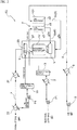
- Fig. 1 shows the configuration of the fuel cell system S1 according to the present invention.
- the fuel cell system S1 is a system constructed by adopting a solid oxide fuel cell SOFC (hereinafter, referred to as a "fuel cell body"), and is configured to include a fuel cell body 101; a fuel gas supply system 4 for supplying a fuel gas g1 (specifically, a gas containing hydrogen and carbon monoxide) to the fuel cell body 101; an oxidizing gas supply system 5 for supplying an oxidizing gas g2 (specifically, an air containing oxygen) to the fuel cell body 101; and an off-gas treatment system 6 (6a and 6c) for treating an off-gas (an anode off-gas g3a and a cathode off-gas g3c) exhausted from the fuel cell body 101 at the time of electric power generation in which the fuel cell body 101 generates electric power.
- a fuel gas supply system 4 for supplying a fuel gas g1 (specifically, a gas containing hydrogen and carbon monoxide) to the fuel cell body 101
- an oxidizing gas supply system 5 for supplying
- the fuel cell body 101 is connected to an electric power load (for example, a power conditioner (not shown)), and can extract the generated electric power.
- an electric power load for example, a power conditioner (not shown)
- the fuel cell body 101 is configured to include a large number of fuel cell stacks s, and as shown in Fig. 1 , a solid oxide-type solid electrolyte s1 is configured to include a fuel electrode (anode) s2 on one surface and an air electrode (cathode) s3 on the other surface.
- the solid oxide-type solid electrolyte s1 for example, zirconia doped with at least one selected from rare earth elements such as Y and Sc, which is YSZ, can be mentioned, and ceria doped with at least one selected from the rare earth elements, or lanthanum gallate doped with at least one selected from Sr and Mg can also be mentioned.
- a composite material thereof can also be used.
- a cermet of Ni and YSZ is adopted, and as a separator thereof, an alloy or oxide containing Cr, for example, a perovskite-type oxide such as a LaCrO 3 -based oxide, a Fe-Cr alloy which is ferritic stainless steel, a Fe-Cr-Ni alloy which is austenitic stainless steel, a Ni-Cr alloy which is a nickel-based alloy, or the like can be adopted.
- the fuel gas g1 is supplied to the fuel electrode s2 and the oxidizing gas g2 is supplied to the air electrode s3.
- the fuel gas supply system 4 includes a steam reformer 1 as a core, which receives supply of a hydrocarbon fuel (for example, a city gas 13A containing CH 4 as a main component, or the like), which is a raw fuel g0, and steam v to perform steam reforming, and the fuel gas g1 obtained by the steam reforming in the steam reformer 1 is supplied to each fuel electrode s2 of the fuel cell stacks s provided in large numbers in the fuel cell body 101.
- a hydrocarbon fuel for example, a city gas 13A containing CH 4 as a main component, or the like
- the city gas 13A generally contains methane derived from a natural gas as a main component and also contains ethane, propane, and butane, but a sulfur-containing substance (sulfur component) such as dimethyl sulfide (DMS) and tertiary butyl mercaptan is also contained as an odorant.
- sulfur component sulfur component
- DMS dimethyl sulfide
- tertiary butyl mercaptan tertiary butyl mercaptan
- a raw fuel pump P1 for supplying the raw fuel g0 is provided and a heater 2 for heating the supplied raw fuel g0 and a desulfurization reactor 3 for removing a sulfur component contained in the raw fuel g0 from the raw fuel g0 are provided.
- a copper-zinc-based desulfurizing agent is stored in the desulfurization reactor 3, and the sulfur component contained in the raw fuel g0 is reduced so that a sulfur content in the desulfurization reactor 3 is 1 vol. ppb or less (more preferably 0.1 vol. ppb or less).
- a copper compound for example, copper nitrate, copper acetate, or the like
- a zinc compound for example, zinc nitrate, zinc acetate, or the like
- an aluminum compound for example, aluminum nitrate, sodium aluminate, or the like
- a combustor 7 is provided for heating the steam reformer 1.
- a part of the anode off-gas g3a exhausted from the fuel electrode s2 is supplied as a combustion gas and the cathode off-gas g3c exhausted from the air electrode s3 is supplied, and a combustion component (hydrogen, hydrocarbon, and carbon monoxide) contained in the anode off-gas g3a is combusted with oxygen contained in the cathode off-gas g3c.
- a combustion component hydrogen, hydrocarbon, and carbon monoxide
- the raw fuel g0 sucked and transported by the raw fuel pump P1 is desulfurized and flows into the steam reformer 1.
- the residue of the anode off-gas g3a exhausted from the fuel electrode s2 is circulated as a steam reforming gas by a circulation pump P2.
- the circulation path is referred to as an anode off-gas circulation path 8 in the present invention, and the circulation path 8 will be described later.
- the steam reformer 1 is thermally connected to the combustor 7 for combusting the anode off-gas g3a exhausted from the fuel cell body 101, and uses heat generated in the combustor 7 to perform steam reforming.
- a steam reforming catalyst is stored in the steam reformer 1, and examples of this type of catalyst include a ruthenium-based catalyst and a nickel-base catalyst. Furthermore, specifically, a Ru/Al 2 O 3 catalyst obtained by supporting a ruthenium component on an alumina support, a Ni/Al 2 O 3 catalyst obtained by supporting a nickel component on an alumina support, or the like can be used.
- a reaction performed in the steam reformer 1 can be expressed as the following two results, and is an endothermic reaction performed by obtaining heat from the outside.
- [Chem. 1] CH 4 + H 2 O ⁇ CO + 3H 2
- [Chem. 2] CH 4 + 2H 2 O ⁇ CO 2 + 4H 2
- the oxidizing gas supply system 5 supplies the oxidizing gas g2 to each air electrode s3 of the fuel cell stacks s provided in large numbers in the fuel cell body 101.
- a heat source for preheating the air may be an exhaust gas exhausted from the combustor 7. That is, heat of an exhaust gas gex of the combustor 7 is recovered by a heat recovery device 10ex, used for preheating the air, cooling by sending the air to the steam reformer 1 unique to the present application, and heating the anode off-gas g3a whose steam partial pressure has been adjusted, and also used for general heat utilization such as hot water supply.
- the off-gas treatment system 6 includes two systems, that is, an anode off-gas treatment system 6a for receiving the off-gas from the fuel electrode s2 side of the fuel cell body 101 and a cathode off-gas treatment system 6c for receiving the off-gas from the air electrode s3 side.
- the anode off-gas treatment system 6a is branched by a distributor 10 on a downstream side, one is connected to the combustor 7, and the other is connected to the steam reformer 1.
- the distributor 10 is configured so that the anode off-gas g3a can be distributed to the steam reformer 1 roughly in an anode off-gas amount of 3 when an anode off-gas amount sent to the combustor 7 is 1.
- This distribution ratio can be optionally set according to a facility condition and an operating condition of the system S1.
- a heat recovery device 11 As a cooling means that gradually cools the gas g3a flowing therein in a vapor phase or a mixed phase, and condensed water w1, which is generated mainly by cooling determined by a heat-resistant temperature of a pump, is exhausted from the cooler 12.
- the humidistat 13 is a so-called condenser, and operates as a condensing means that condenses and removes the steam v contained in the gas g3a flowing therein and exhausts condensed water w2. Therefore, in the humidistat 13, the steam partial pressure of the gas flowing therein is adjusted according to the condensation temperature. Depending on the facility condition and the operating condition, it is possible to omit the humidistat 13 by adding a function of adjusting the condensation temperature in the humidistat 13 to the cooler 12. In the case of this configuration, the cooler 12 operates as the condensing means in the present invention.
- the heater 14 operates as a temperature raising means that raises the temperature of the gas g3a flowing therein in a vapor phase. Regarding the operating conditions of these devices 11, 12, P2, 13, and 14, the temperature of the gas g3a flowing through each part and the like will be described in detail in the section of the operating conditions of the fuel cell system S1, will be described later.
- a part of the anode off-gas g3a whose steam partial pressure is adjusted is circulated to a mixer 15 through the circulation pump P2, used for the steam reforming in the steam reformer 1, and supplied to the fuel electrode s2 of the fuel cell body 101.
- the steam v used for the steam reforming in the steam reformer 1 is supplied through the anode off-gas circulation path 8 (anode off-gas treatment system 6a).
- Fig. 1 shows control elements forming the main part of the present invention in a control unit C of the fuel cell system S1.
- the control unit C receives an electric power load required for the system S1 and outputs an instruction to the raw fuel pump P1 according to the supply amount of the raw fuel required to cope with the electric power load. Furthermore, the blower B is instructed for the corresponding supply amount of the air.
- the circulation pump P2 is instructed for the anode off-gas circulation amount and the humidistat 13 is instructed for a humidistat outlet temperature.
- the steam partial pressure of the anode off-gas g3a which returns to the mixer 15 through the anode off-gas circulation path 8 and is mixed with the raw fuel g0, is maintained in an appropriate range, a S/C ratio which is a ratio (molar ratio) between the amounts of the steam and the carbon input to the fuel cell system S1 (specifically, input to the steam reformer 1) can be maintained in a desired state, and thus highly efficient electric power generation is performed.
- control unit C is the control means in the present invention.
- control means and the condensing means of the present invention cooperate to become a S/C ratio adjusting means of the fuel cell system S1.
- the fuel cell system S2 also includes the current solid oxide fuel cell SOFC as a core, but when electric power is generated using hydrocarbon as the raw fuel g0, the steam v contained in the combusted gas of the hydrocarbon fuel generated in the steam reformer 1 is condensed in a condenser 22, and the steam v obtained by evaporating the condensed water w is used for steam reforming.
- water contained in the combusted gas is used for steam reforming, and thus a water quality maintenance device 20 is required.
- a fuel cell fuel cell body 101 in which the reformed gas obtained by the steam reformer 1 is supplied as the fuel gas g1 to the fuel electrode s2 and the oxidizing gas g2 is separately supplied to cause a cell reaction.
- the oxidizing gas supply system 5 for supplying the oxidizing gas g2 to the air electrode s3 includes the blower B and the heater 9, and the cathode off-gas g3c exhausted from the air electrode s3 is introduced to the steam reformer 1 and used for combustion in a heating burner V provided in the device.
- a portion surrounded by a box at a center of the steam reformer 1 is a reforming reaction unit 1V which performs steam reforming by using the steam v generated from an evaporation unit 23.
- the fuel gas g1 subjected to the steam reforming is supplied to the fuel electrode s2 and used for electric power generation.
- the anode off-gas g3a exhausted from the fuel electrode s2 contains a fuel which is a combustion component, and is supplied to the burner V provided in the steam reformer 1 to be used for combustion.
- the anode off-gas circulation path 8 according to the present invention which is described above in the embodiment, is not provided, and accordingly the distributor 10, the heat recovery device 11, the cooler 12, the circulation pump P2, the humidistat 13, and the heater 14 are not provided.
- a reaction equilibrium temperature of the steam reformer 1 could be maintained at 670°C by setting the S/C ratio in the steam reformer 1 to 2.6 and combusting a part of the anode off-gas g3a by the combustor 7.
- the concentrations (corresponding to the partial pressure) of the raw fuel at the inlet and the outlet of the fuel electrode were about 0.3 vol.%, and the concentrations (corresponding to the partial pressure) of the fuel gas (hydrogen + carbon monoxide) at the inlet and the outlet of the fuel electrode were about 49 vol.% and about 15 vol.%. Moreover, the concentrations (corresponding to the partial pressure) of the steam at the inlet and the outlet of the fuel electrode were 26 vol.% and 50 vol.%.
- the fuel cell system S2 as the comparative example will be described.
- the city gas (13A) was used as the raw fuel
- the latest solid oxide fuel cell SOFC was incorporated
- parameters (direct current/alternating current conversion efficiency and the like) required for the investigation the same values were used for strict comparison except for the present invention.
- the anode off-gas g3a can be combusted using the cathode off-gas g3c in the burner V provided in the steam reformer 1 to maintain the reaction equilibrium temperature at 670°C.
- the concentrations (corresponding to the partial pressure) of the raw fuel at the inlet and the outlet of the fuel electrode were about 1 vol.%, and the concentrations (corresponding to the partial pressure) of the fuel gas (hydrogen + carbon monoxide) at the inlet and the outlet of the fuel electrode were about 67 vol.% and about 14 vol.%. Moreover, the concentrations (corresponding to the partial pressure) of the steam at the inlet and the outlet of the fuel electrode were 23 vol.% and 70 vol.%.
- the anode off-gas is used for heating in the steam reformer 1 and then merely released to the outside.
- the anode off-gas is circulated to the steam reformer 1 to reduce the fuel utilization rate and to secure the fuel partial pressure (fuel gas partial pressure) at the outlet of the fuel cell, and thus the electric power generation amount (electric power generation efficiency) can be improved.
- the amount of the fuel supplied to the fuel cell is increased, and thus the fuel utilization rate of the fuel cell can be reduced (the consumption rate of the fuel required for the fuel cell is mitigated, which is advantageous for the fuel cell performance, and the difference in partial pressure at the inlet and the outlet of the fuel electrode is reduced, which levels the temperature distribution accompanying the electric power generation and is also advantageous for durability).
- the gas temperature is lowered in order to use a general-purpose pump, the S/C ratio can also be adjusted to some extent close to a target value (2.6 for this time).
- the fuel cell system according to the present invention can be operated at the S/C ratio, for example in a range of 1.5 to 3.5 and preferably a range of 1.5 to 3.0, but since the sulfur content in the hydrocarbon fuel input to the steam reformer 1 is reduced to 1 vol. ppb, in particular, even under the condition in which the S/C ratio is in a relatively low range, the stable operation can be realized for a long period of time.
- the humidistat 13 operating as the condensing means in the present embodiment cooperates with the control unit C which is the control means to operate as a S/C ratio adjusting means that adjusts a S/C ratio which is a ratio of the amount of the steam circulated to the steam reformer 1 to the amount of the carbon input to the steam reformer 1.
- a flow rate of the fuel gas at the inlet of the fuel electrode is calculated based on the fuel utilization rate in the fuel cell, the amount of the hydrocarbon fuel which is the raw fuel input to the steam reformer 1 is calculated based on the S/C ratio set in the steam reformer 1, and the steam amount (corresponding to the steam partial pressure) capable of introducing this amount of the raw fuel is determined.
- the target value of the S/C ratio is a value which is preset as an appropriate S/C ratio corresponding to the electric power load, and the minimum fuel gas concentration (for example, 12 vol.%) is set as a minimum value of the fuel gas concentration at the outlet of the fuel electrode.
Landscapes
- Chemical & Material Sciences (AREA)
- Chemical Kinetics & Catalysis (AREA)
- Engineering & Computer Science (AREA)
- Sustainable Energy (AREA)
- General Chemical & Material Sciences (AREA)
- Electrochemistry (AREA)
- Life Sciences & Earth Sciences (AREA)
- Manufacturing & Machinery (AREA)
- Sustainable Development (AREA)
- Combustion & Propulsion (AREA)
- Organic Chemistry (AREA)
- General Health & Medical Sciences (AREA)
- Inorganic Chemistry (AREA)
- Health & Medical Sciences (AREA)
- Fuel Cell (AREA)
Applications Claiming Priority (2)
| Application Number | Priority Date | Filing Date | Title |
|---|---|---|---|
| JP2018040449 | 2018-03-07 | ||
| PCT/JP2019/008945 WO2019172337A1 (ja) | 2018-03-07 | 2019-03-06 | 燃料電池システム及び燃料電池システムの運転方法 |
Publications (2)
| Publication Number | Publication Date |
|---|---|
| EP3764446A1 true EP3764446A1 (de) | 2021-01-13 |
| EP3764446A4 EP3764446A4 (de) | 2021-11-24 |
Family
ID=67845577
Family Applications (1)
| Application Number | Title | Priority Date | Filing Date |
|---|---|---|---|
| EP19765073.2A Pending EP3764446A4 (de) | 2018-03-07 | 2019-03-06 | Brennstoffzellensystem und verfahren zum betrieb des brennstoffzellensystems |
Country Status (7)
| Country | Link |
|---|---|
| US (1) | US11367887B2 (de) |
| EP (1) | EP3764446A4 (de) |
| JP (1) | JP7155241B2 (de) |
| KR (1) | KR102744251B1 (de) |
| CN (1) | CN111788731B (de) |
| CA (1) | CA3091445A1 (de) |
| WO (1) | WO2019172337A1 (de) |
Cited By (1)
| Publication number | Priority date | Publication date | Assignee | Title |
|---|---|---|---|---|
| AT526262A1 (de) * | 2022-07-14 | 2024-01-15 | Avl List Gmbh | Temperiergehäuse für ein Temperieren von Komponenten eines Brennstoffzellensystems |
Families Citing this family (10)
| Publication number | Priority date | Publication date | Assignee | Title |
|---|---|---|---|---|
| JP7120445B2 (ja) * | 2019-03-27 | 2022-08-17 | 日産自動車株式会社 | 燃料電池システム及び燃料電池システムの制御方法 |
| JP2021103643A (ja) * | 2019-12-25 | 2021-07-15 | 富士電機株式会社 | 燃料電池システム及び運転方法 |
| DE102020208497A1 (de) | 2020-07-07 | 2022-01-13 | Robert Bosch Gesellschaft mit beschränkter Haftung | Hochtemperaturbrennstoffzellenvorrichtung |
| US12512495B2 (en) * | 2021-05-11 | 2025-12-30 | Mitsubishi Electric Corporation | Fuel cell system |
| KR102408377B1 (ko) * | 2021-08-30 | 2022-06-14 | 주식회사 미코파워 | 연료전지 시스템 |
| CN114156506B (zh) * | 2021-11-26 | 2023-10-20 | 北京理工大学 | 一种车载燃料电池控制系统、方法、电动汽车、重型车辆 |
| CN118451575A (zh) * | 2021-12-02 | 2024-08-06 | 维萨电力系统有限公司 | 包含喷射器的燃料电池系统 |
| DE102023201610A1 (de) * | 2023-02-22 | 2024-08-22 | Robert Bosch Gesellschaft mit beschränkter Haftung | Brennstoffzellenvorrichtung und Brennstoffzellensystem |
| CN116207310A (zh) * | 2023-03-20 | 2023-06-02 | 中自环保科技股份有限公司 | 一种尾气循环利用的sofc系统及启动方法 |
| WO2025154582A1 (ja) * | 2024-01-15 | 2025-07-24 | 京セラ株式会社 | 固体酸化物形燃料電池セルスタック、燃料電池モジュール、及び燃料電池装置 |
Family Cites Families (18)
| Publication number | Priority date | Publication date | Assignee | Title |
|---|---|---|---|---|
| CA2448715C (en) * | 2002-11-11 | 2011-07-05 | Nippon Telegraph And Telephone Corporation | Fuel cell power generating system with two fuel cells of different types and method of controlling the same |
| WO2005050768A1 (en) * | 2003-11-19 | 2005-06-02 | Questair Technologies Inc. | High efficiency load-following solid oxide fuel cell systems |
| JP4751608B2 (ja) | 2004-12-24 | 2011-08-17 | アイシン精機株式会社 | カソード用ポンプまたはブロアの制御装置、および燃料電池システム |
| JP4946087B2 (ja) * | 2006-02-17 | 2012-06-06 | 株式会社日立製作所 | 燃料電池システム |
| WO2009093456A1 (ja) * | 2008-01-23 | 2009-07-30 | Panasonic Corporation | 燃料電池システム |
| FI123690B (fi) * | 2009-10-30 | 2013-09-30 | Convion Oy | Menetelmä ja järjestely anoditakaisinkierrätyksen ohjaamiseksi |
| JP2011210634A (ja) | 2010-03-30 | 2011-10-20 | Jx Nippon Oil & Energy Corp | 燃料電池システム |
| JPWO2012165097A1 (ja) * | 2011-06-01 | 2015-02-23 | コニカミノルタ株式会社 | 2次電池型燃料電池システム |
| US9105888B2 (en) * | 2011-10-07 | 2015-08-11 | GM Global Technology Operations LLC | Anode purge and drain valve strategy for fuel cell system |
| FI20116281A7 (fi) | 2011-12-16 | 2013-06-17 | Waertsilae Finland Oy | Menetelmä ja järjestely kennon anodikaasun vesipitoisuuden säätämiseksi |
| JP2014089919A (ja) | 2012-10-31 | 2014-05-15 | Panasonic Corp | 固体酸化物形燃料電池システム |
| US9966621B2 (en) * | 2013-01-24 | 2018-05-08 | Panasonic Intellectual Property Management Co., Ltd. | Fuel cell system |
| US9515329B2 (en) * | 2013-04-11 | 2016-12-06 | Panasonic Intellectual Property Management Co., Ltd. | Fuel cell system |
| JP2015043263A (ja) * | 2013-08-26 | 2015-03-05 | 日立造船株式会社 | 固体酸化物型燃料電池における燃料極排ガスの循環再利用方法 |
| US10361444B2 (en) * | 2013-12-31 | 2019-07-23 | General Electric Company | Solid-oxide fuel cell systems |
| EP3227230B1 (de) * | 2014-12-01 | 2020-01-01 | SOLIDpower SA | Sofc-system und verfahren zum betreiben eines sofc-systems |
| DE102015114613A1 (de) * | 2015-09-01 | 2017-03-02 | Siqens Gmbh | Verfahren und Vorrichtung zum parallelen Kondensieren und Verdampfen für ein Brennstoffzellensystem mit einer Kondensations-/Verdampfungs-Vorrichtung sowie ein Brennstoffzellensystem mit einer solchen Kondensations-/Verdampfungs-Vorrichtung |
| CN106910912B (zh) * | 2015-12-18 | 2020-06-30 | 通用电气公司 | 燃料电池系统及其操作方法及燃料电池发电厂 |
-
2019
- 2019-03-06 CN CN201980017321.3A patent/CN111788731B/zh active Active
- 2019-03-06 KR KR1020207019168A patent/KR102744251B1/ko active Active
- 2019-03-06 EP EP19765073.2A patent/EP3764446A4/de active Pending
- 2019-03-06 WO PCT/JP2019/008945 patent/WO2019172337A1/ja not_active Ceased
- 2019-03-06 JP JP2020505086A patent/JP7155241B2/ja active Active
- 2019-03-06 US US16/976,205 patent/US11367887B2/en active Active
- 2019-03-06 CA CA3091445A patent/CA3091445A1/en active Pending
Cited By (2)
| Publication number | Priority date | Publication date | Assignee | Title |
|---|---|---|---|---|
| AT526262A1 (de) * | 2022-07-14 | 2024-01-15 | Avl List Gmbh | Temperiergehäuse für ein Temperieren von Komponenten eines Brennstoffzellensystems |
| AT526262B1 (de) * | 2022-07-14 | 2024-07-15 | Avl List Gmbh | Temperiergehäuse für ein Temperieren von Komponenten eines Brennstoffzellensystems |
Also Published As
| Publication number | Publication date |
|---|---|
| US20210005910A1 (en) | 2021-01-07 |
| JP7155241B2 (ja) | 2022-10-18 |
| JPWO2019172337A1 (ja) | 2021-03-11 |
| CA3091445A1 (en) | 2019-09-12 |
| WO2019172337A1 (ja) | 2019-09-12 |
| KR102744251B1 (ko) | 2024-12-17 |
| CN111788731A (zh) | 2020-10-16 |
| CN111788731B (zh) | 2024-03-12 |
| EP3764446A4 (de) | 2021-11-24 |
| KR20200128653A (ko) | 2020-11-16 |
| US11367887B2 (en) | 2022-06-21 |
Similar Documents
| Publication | Publication Date | Title |
|---|---|---|
| US11367887B2 (en) | Fuel cell system and method for operating fuel cell system | |
| CA2561025A1 (en) | Fuel processing method and system | |
| EP3875426B1 (de) | Brennstoffzellensystem und regenerationsverfahren für abgas | |
| KR101563455B1 (ko) | 고온 연료 전지 시스템에 대한 재순환을 이용하는 방법 및 어레인지먼트 | |
| JP4450623B2 (ja) | 燃料電池システム | |
| JP2008300251A (ja) | 燃料電池コージェネレーション装置 | |
| JP2009048854A (ja) | 燃料電池発電装置およびその制御方法 | |
| US20190190050A1 (en) | Solid oxide fuel cell system | |
| JP6688818B2 (ja) | 燃料電池システム | |
| US10079398B2 (en) | Transition arrangement and process of a fuel cell system operation state | |
| JP5134309B2 (ja) | 燃料電池発電装置およびその制御方法 | |
| JP5395168B2 (ja) | 水素生成装置および燃料電池システム | |
| JP3872006B2 (ja) | 燃料電池発電システム | |
| JP4620399B2 (ja) | 燃料電池発電システムの制御方法 | |
| JP3886887B2 (ja) | 燃料電池発電システム | |
| JP4847759B2 (ja) | 水素製造装置の運転方法、水素製造装置および燃料電池発電装置 | |
| JP2005268190A (ja) | 燃料電池システム | |
| EP3214039B1 (de) | Wasserstofferzeugungsvorrichtung, verfahren zum betrieb davon und brennstoffzellensystem | |
| JP2007141693A (ja) | 燃料電池発電装置 | |
| JP2005071813A (ja) | 燃料電池発電システム | |
| JP2010020965A (ja) | 燃料電池発電システムおよびその動作方法 | |
| JP2007087781A (ja) | 燃料電池発電システムのアノードのパージ方法 | |
| JP2015133201A (ja) | 燃料電池システム |
Legal Events
| Date | Code | Title | Description |
|---|---|---|---|
| STAA | Information on the status of an ep patent application or granted ep patent |
Free format text: STATUS: THE INTERNATIONAL PUBLICATION HAS BEEN MADE |
|
| PUAI | Public reference made under article 153(3) epc to a published international application that has entered the european phase |
Free format text: ORIGINAL CODE: 0009012 |
|
| STAA | Information on the status of an ep patent application or granted ep patent |
Free format text: STATUS: REQUEST FOR EXAMINATION WAS MADE |
|
| 17P | Request for examination filed |
Effective date: 20200715 |
|
| AK | Designated contracting states |
Kind code of ref document: A1 Designated state(s): AL AT BE BG CH CY CZ DE DK EE ES FI FR GB GR HR HU IE IS IT LI LT LU LV MC MK MT NL NO PL PT RO RS SE SI SK SM TR |
|
| AX | Request for extension of the european patent |
Extension state: BA ME |
|
| DAV | Request for validation of the european patent (deleted) | ||
| DAX | Request for extension of the european patent (deleted) | ||
| A4 | Supplementary search report drawn up and despatched |
Effective date: 20211027 |
|
| RIC1 | Information provided on ipc code assigned before grant |
Ipc: H01M 8/04014 20160101ALN20211021BHEP Ipc: H01M 8/124 20160101ALN20211021BHEP Ipc: H01M 8/04746 20160101ALN20211021BHEP Ipc: H01M 8/04029 20160101ALN20211021BHEP Ipc: H01M 8/04537 20160101ALN20211021BHEP Ipc: H01M 8/04119 20160101ALN20211021BHEP Ipc: H01M 8/1231 20160101ALI20211021BHEP Ipc: H01M 8/0662 20160101ALI20211021BHEP Ipc: H01M 8/0612 20160101ALI20211021BHEP Ipc: H01M 8/04701 20160101ALI20211021BHEP Ipc: H01M 8/04492 20160101ALI20211021BHEP Ipc: C01B 3/38 20060101ALI20211021BHEP Ipc: H01M 8/04828 20160101AFI20211021BHEP |
|
| STAA | Information on the status of an ep patent application or granted ep patent |
Free format text: STATUS: EXAMINATION IS IN PROGRESS |
|
| 17Q | First examination report despatched |
Effective date: 20230329 |
|
| R17C | First examination report despatched (corrected) |
Effective date: 20230614 |