EP3214246B1 - Dämpfungsvorrichtung - Google Patents
Dämpfungsvorrichtung Download PDFInfo
- Publication number
- EP3214246B1 EP3214246B1 EP16192735.5A EP16192735A EP3214246B1 EP 3214246 B1 EP3214246 B1 EP 3214246B1 EP 16192735 A EP16192735 A EP 16192735A EP 3214246 B1 EP3214246 B1 EP 3214246B1
- Authority
- EP
- European Patent Office
- Prior art keywords
- piston
- housing
- damping device
- piston rod
- base
- Prior art date
- Legal status (The legal status is an assumption and is not a legal conclusion. Google has not performed a legal analysis and makes no representation as to the accuracy of the status listed.)
- Active
Links
Images


Classifications
-
- E—FIXED CONSTRUCTIONS
- E05—LOCKS; KEYS; WINDOW OR DOOR FITTINGS; SAFES
- E05F—DEVICES FOR MOVING WINGS INTO OPEN OR CLOSED POSITION; CHECKS FOR WINGS; WING FITTINGS NOT OTHERWISE PROVIDED FOR, CONCERNED WITH THE FUNCTIONING OF THE WING
- E05F3/00—Closers or openers with braking devices, e.g. checks; Construction of pneumatic or liquid braking devices
- E05F3/04—Closers or openers with braking devices, e.g. checks; Construction of pneumatic or liquid braking devices with liquid piston brakes
- E05F3/10—Closers or openers with braking devices, e.g. checks; Construction of pneumatic or liquid braking devices with liquid piston brakes with a spring, other than a torsion spring, and a piston, the axes of which are the same or lie in the same direction
- E05F3/108—Closers or openers with braking devices, e.g. checks; Construction of pneumatic or liquid braking devices with liquid piston brakes with a spring, other than a torsion spring, and a piston, the axes of which are the same or lie in the same direction with piston rod protruding from the closer housing; Telescoping closers
-
- E—FIXED CONSTRUCTIONS
- E05—LOCKS; KEYS; WINDOW OR DOOR FITTINGS; SAFES
- E05D—HINGES OR SUSPENSION DEVICES FOR DOORS, WINDOWS OR WINGS
- E05D5/00—Construction of single parts, e.g. the parts for attachment
- E05D5/02—Parts for attachment, e.g. flaps
- E05D5/06—Bent flaps
- E05D5/065—Bent flaps specially adapted for cabinets or furniture
-
- E—FIXED CONSTRUCTIONS
- E05—LOCKS; KEYS; WINDOW OR DOOR FITTINGS; SAFES
- E05F—DEVICES FOR MOVING WINGS INTO OPEN OR CLOSED POSITION; CHECKS FOR WINGS; WING FITTINGS NOT OTHERWISE PROVIDED FOR, CONCERNED WITH THE FUNCTIONING OF THE WING
- E05F3/00—Closers or openers with braking devices, e.g. checks; Construction of pneumatic or liquid braking devices
- E05F3/04—Closers or openers with braking devices, e.g. checks; Construction of pneumatic or liquid braking devices with liquid piston brakes
- E05F3/12—Special devices controlling the circulation of the liquid, e.g. valve arrangement
-
- E—FIXED CONSTRUCTIONS
- E05—LOCKS; KEYS; WINDOW OR DOOR FITTINGS; SAFES
- E05F—DEVICES FOR MOVING WINGS INTO OPEN OR CLOSED POSITION; CHECKS FOR WINGS; WING FITTINGS NOT OTHERWISE PROVIDED FOR, CONCERNED WITH THE FUNCTIONING OF THE WING
- E05F3/00—Closers or openers with braking devices, e.g. checks; Construction of pneumatic or liquid braking devices
- E05F3/20—Closers or openers with braking devices, e.g. checks; Construction of pneumatic or liquid braking devices in hinges
-
- E—FIXED CONSTRUCTIONS
- E05—LOCKS; KEYS; WINDOW OR DOOR FITTINGS; SAFES
- E05F—DEVICES FOR MOVING WINGS INTO OPEN OR CLOSED POSITION; CHECKS FOR WINGS; WING FITTINGS NOT OTHERWISE PROVIDED FOR, CONCERNED WITH THE FUNCTIONING OF THE WING
- E05F5/00—Braking devices, e.g. checks; Stops; Buffers
- E05F5/006—Braking devices, e.g. checks; Stops; Buffers for hinges having a cup-shaped fixing part, e.g. for attachment to cabinets or furniture
-
- E—FIXED CONSTRUCTIONS
- E05—LOCKS; KEYS; WINDOW OR DOOR FITTINGS; SAFES
- E05F—DEVICES FOR MOVING WINGS INTO OPEN OR CLOSED POSITION; CHECKS FOR WINGS; WING FITTINGS NOT OTHERWISE PROVIDED FOR, CONCERNED WITH THE FUNCTIONING OF THE WING
- E05F5/00—Braking devices, e.g. checks; Stops; Buffers
- E05F5/02—Braking devices, e.g. checks; Stops; Buffers specially for preventing the slamming of swinging wings during final closing movement, e.g. jamb stops
-
- F—MECHANICAL ENGINEERING; LIGHTING; HEATING; WEAPONS; BLASTING
- F16—ENGINEERING ELEMENTS AND UNITS; GENERAL MEASURES FOR PRODUCING AND MAINTAINING EFFECTIVE FUNCTIONING OF MACHINES OR INSTALLATIONS; THERMAL INSULATION IN GENERAL
- F16F—SPRINGS; SHOCK-ABSORBERS; MEANS FOR DAMPING VIBRATION
- F16F9/00—Springs, vibration-dampers, shock-absorbers, or similarly-constructed movement-dampers using a fluid or the equivalent as damping medium
- F16F9/32—Details
- F16F9/34—Special valve constructions; Shape or construction of throttling passages
- F16F9/3405—Throttling passages in or on piston body, e.g. slots
-
- F—MECHANICAL ENGINEERING; LIGHTING; HEATING; WEAPONS; BLASTING
- F16—ENGINEERING ELEMENTS AND UNITS; GENERAL MEASURES FOR PRODUCING AND MAINTAINING EFFECTIVE FUNCTIONING OF MACHINES OR INSTALLATIONS; THERMAL INSULATION IN GENERAL
- F16F—SPRINGS; SHOCK-ABSORBERS; MEANS FOR DAMPING VIBRATION
- F16F9/00—Springs, vibration-dampers, shock-absorbers, or similarly-constructed movement-dampers using a fluid or the equivalent as damping medium
- F16F9/32—Details
- F16F9/34—Special valve constructions; Shape or construction of throttling passages
- F16F9/346—Throttling passages in the form of slots arranged in cylinder walls
-
- E—FIXED CONSTRUCTIONS
- E05—LOCKS; KEYS; WINDOW OR DOOR FITTINGS; SAFES
- E05Y—INDEXING SCHEME ASSOCIATED WITH SUBCLASSES E05D AND E05F, RELATING TO CONSTRUCTION ELEMENTS, ELECTRIC CONTROL, POWER SUPPLY, POWER SIGNAL OR TRANSMISSION, USER INTERFACES, MOUNTING OR COUPLING, DETAILS, ACCESSORIES, AUXILIARY OPERATIONS NOT OTHERWISE PROVIDED FOR, APPLICATION THEREOF
- E05Y2201/00—Constructional elements; Accessories therefor
- E05Y2201/20—Brakes; Disengaging means; Holders; Stops; Valves; Accessories therefor
- E05Y2201/21—Brakes
-
- E—FIXED CONSTRUCTIONS
- E05—LOCKS; KEYS; WINDOW OR DOOR FITTINGS; SAFES
- E05Y—INDEXING SCHEME ASSOCIATED WITH SUBCLASSES E05D AND E05F, RELATING TO CONSTRUCTION ELEMENTS, ELECTRIC CONTROL, POWER SUPPLY, POWER SIGNAL OR TRANSMISSION, USER INTERFACES, MOUNTING OR COUPLING, DETAILS, ACCESSORIES, AUXILIARY OPERATIONS NOT OTHERWISE PROVIDED FOR, APPLICATION THEREOF
- E05Y2201/00—Constructional elements; Accessories therefor
- E05Y2201/20—Brakes; Disengaging means; Holders; Stops; Valves; Accessories therefor
- E05Y2201/252—Type of friction
- E05Y2201/254—Fluid or viscous friction
- E05Y2201/256—Fluid or viscous friction with pistons or vanes
-
- E—FIXED CONSTRUCTIONS
- E05—LOCKS; KEYS; WINDOW OR DOOR FITTINGS; SAFES
- E05Y—INDEXING SCHEME ASSOCIATED WITH SUBCLASSES E05D AND E05F, RELATING TO CONSTRUCTION ELEMENTS, ELECTRIC CONTROL, POWER SUPPLY, POWER SIGNAL OR TRANSMISSION, USER INTERFACES, MOUNTING OR COUPLING, DETAILS, ACCESSORIES, AUXILIARY OPERATIONS NOT OTHERWISE PROVIDED FOR, APPLICATION THEREOF
- E05Y2201/00—Constructional elements; Accessories therefor
- E05Y2201/20—Brakes; Disengaging means; Holders; Stops; Valves; Accessories therefor
- E05Y2201/262—Type of motion, e.g. braking
- E05Y2201/264—Type of motion, e.g. braking linear
-
- E—FIXED CONSTRUCTIONS
- E05—LOCKS; KEYS; WINDOW OR DOOR FITTINGS; SAFES
- E05Y—INDEXING SCHEME ASSOCIATED WITH SUBCLASSES E05D AND E05F, RELATING TO CONSTRUCTION ELEMENTS, ELECTRIC CONTROL, POWER SUPPLY, POWER SIGNAL OR TRANSMISSION, USER INTERFACES, MOUNTING OR COUPLING, DETAILS, ACCESSORIES, AUXILIARY OPERATIONS NOT OTHERWISE PROVIDED FOR, APPLICATION THEREOF
- E05Y2900/00—Application of doors, windows, wings or fittings thereof
- E05Y2900/20—Application of doors, windows, wings or fittings thereof for furniture, e.g. cabinets
Definitions
- the present invention is related to a damping device.
- some specific furniture such as a door or a cabinet may be installed with a damping device.
- the damping can be utilized to provide damping effect when a first component is moved to switch from an open state to a close state relative to a second component, in order to mitigate movement of the first component being closed relative to the second component.
- US patent numbers US 9,021,656 B2 , US 9,057,214 B2 and US 8,925,151 B2 discloses furniture hinges with similar techniques.
- US 9,021,656 B2 discloses a furniture damper comprises a slider (13), a piston (22) and a piston rod (17). According to FIGs.
- the hinge arm (12) can be fixed to a fixing part of the furniture, and the box (13) can be fixed to a door of the furniture.
- the hinge (10) also comprises a decelerating device (22) connected to the box (13).
- the decelerating device (22) comprises a slider (24) having a first cylindrical part (24') and a second cylindrical part (24").
- the first cylindrical part (24') is configured to accommodate a piston (27) and a piston rod (31) .
- the second cylindrical part (24") is configured to accommodate a return spring means (25) .
- such type of the decelerating device (22) has a more complex structure due to the slider (24) having the first cylindrical part (24') and the second cylindrical part (24") for accommodating related components. Therefore, damping devices with different structures can be provided to bring more options to the market.
- the present invention aims at providing a damping device with an alternative damping medium flow arrangement.
- the claimed damping device comprises a housing, a cover assembly, a piston rod, a piston and an elastic member.
- the housing has an inner wall defining a chamber, and an opening communicating with the chamber.
- the chamber is filled with a damping medium.
- the cover assembly is arranged adjacent to the opening of the housing.
- the piston rod penetrates through the cover assembly.
- the piston is connected to the piston rod and movable relative to the housing.
- the piston comprises an extension part and an expansion part located between the piston rod and the extension part, wherein a width of the expansion part is greater than a width of the piston rod.
- the elastic member is arranged in the chamber of the housing and configured to provide an elastic force to the piston.
- the inner wall of the housing has a groove configured to allow at least one portion of the damping medium to pass through. The groove is parallel to a longitudinal direction of the housing and has a first end and a second end opposite to the first end.
- the damping device according to claim 1 essentially differs from the state of the art in that the groove has a constant cross section area from the first end of the groove to the second end of the groove and in that the first end of the groove is connected to an end of the housing opposite to the opening.
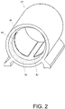
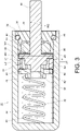
- FIG. 1 is a diagram showing a damping device 20a according to a first embodiment of the present invention.
- the damping device 20a comprises a housing 22, a cover assembly 34, a piston 24, a piston rod 30 and an elastic member 32.
- the damping device 20a further comprises a base 28 and a ring member 26.
- the housing 22 has an inner wall 40 defining a chamber 36, and an opening 38 communicated with the chamber 36.
- the housing 22 is substantially in a cylindrical shape, and the inner wall 40 of the housing 22 has is in a ring shape.
- the inner wall 40 of the housing 22 has a groove 42.
- the groove 42 is arranged along a longitudinal direction of the housing 22.
- the groove 42 in FIG. 2 is shown as a rectangular groove for example, a shape of the groove 42 is not limited thereto.
- the damping medium 52 comprises a fluid, such as oil or a liquid substance.
- the cover assembly 34 is arranged adjacent to the opening 38 of the housing 22.
- the cover assembly 34 comprises a cover body 44, a sleeve member 46 and a seal ring 48.
- the cover body 44 provides a space 50 for accommodating the sleeve member 46.
- the seal ring 48 is sleeved on the cover body 44 and configured to seal the opening 38 of the housing 22.
- the piston 24 is movable relative to the housing 22.
- the piston 24 comprises an extension part 54 and an expansion part 56 located between the piston rod 30 and the extension part 54.
- the piston 24 further comprises a mounting part 58 protruded from the extension part 54.
- the piston 24 and the piston rod 30 can be made of a metal material.
- the piston rod 30, the extension part 54, the expansion part 56 and the mounting part 58 are integrally formed. Therefore, the piston 24 and the piston rod 30 of the present embodiment have better structural strength.
- a width W1 of the expansion part 56 is greater than a width W2 of the piston rod 30; and a width W3 of the extension part 54 is greater than the width W2 of the piston rod 30 and smaller than the width W1 of the expansion part 56.
- the relationship between W1, W2, W3 can be presented as an equation of W1>W3>W2.
- the piston rod 30 penetrates through the cover assembly 34.
- the piston rod 30 penetrates through the sleeve member 46 and the cover body 44, and extends out of the opening 38 of the housing 22.
- a gap 60 is formed between the expansion part 56 and the inner wall 40 of the housing 22.
- the elastic member 32 is arranged in the chamber 36 of the housing 22.
- the elastic member 32 is configured to provide an elastic force to the piston 24, in order to drive one portion of the piston rod 30 to extend out of the opening 38 of the housing 22.
- the base 28 is mounted to the mounting part 58 of the piston 24 and adjacent to the extension part 54.
- the base 28 is arranged in the chamber 36 of the housing 22 and abuts against the elastic member 32.
- the base 28 has at least one hole 62.
- the base 28 can be mounted to the piston 24 by fastening, engaging, screwing, sleeving or riveting.
- the ring member 26 is movably mounted between the expansion part 56 of the piston 24 and the base 28.
- a distance L1 is defined between the expansion part 56 of the piston 24 and the base 28.
- a longitudinal dimension L2 of the ring member 26 is smaller than the distance L1, such that the ring member 26 can be moved between the expansion part 56 of the piston 24 and the base 28.
- the ring member 26 is substantially in a ring shape and is made of a flexible material.
- the ring member 26 has a ring-shaped opening 64 configured to allow the extension part 54 of the piston 24 to pass through.
- a diameter of the ring-shaped opening 64 is greater than a corresponding dimension of the extension part 54 of the piston 24, in order to allow the extension part 54 to pass through the ring-shaped opening 64.
- the portion of the damping medium 52 when one portion of the damping medium 52 flows toward the opening 38, the portion of the damping medium 52 can pass through the at least one hole 62 of the base 28, the ring opening 64 of the ring member 26, the groove 42 or the gap 60.
- the portion of the damping medium 52 can flow from a first side of the expansion part 56 of the piston 24 to a second side of the expansion part 56 of the piston 24 through the groove 42 or the gap 60.
- the ring member 26 is located at a position P relative to the expansion part 56 of the piston 24 for blocking the gap 60 (please refer to FIG. 5 as well) . Therefore, in such state, the portion of the damping medium 52 will be forced to flow to the second side of the expansion part 56 of the piston 24 through the groove 42.
- the base 28 further pushes the elastic member 32, such that the elastic member accumulates the elastic force and the portion of the damping medium 52 is squeezed and continues to flow to the second side of the expansion part 56 of the piston 24 through the groove 42.
- the base 28 and the piston 24 are moved along a second direction D2 in response to the elastic force of the elastic member 32, wherein the second direction D2 is opposite to the first direction D1.
- one portion of the damping medium 52 is squeezed, such that the portion of the damping medium 52 flows from the second side of the expansion part 56 of the piston 24 back to the first side of the expansion part 56 along a direction away from the opening 38.
- the portion of the damping medium 52 can pass through the gap 60; or the portion of the damping medium 52 can pass through the groove 42.
- the base 28 is moved along the second direction D2 in response to the elastic force of the elastic member 32, in order to allow the ring member 26 to be close to the base 28.
- the ring member 26 is moved away from the position P without blocking the gap 60, or the ring member 26 is moved by the backflow of the portion of the damping medium 52 from the position P toward the base 28 for being close to the base 28.
- the ring member 26 can be moved away from the position P accordingly.
- the piston 24 and the piston rod 30 of the damping device 20a are integrally formed into a single component, wherein a width of the expansion part 56 of the piston rod 30 is greater than a width of the piston rod 30.
- the housing 22 has the groove 42 configured to allow the damping medium 52 to pass through.
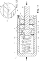
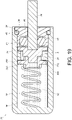
- FIG. 9 is a diagram showing a damping device 20b according to a second embodiment of the present invention.
- a base 100 of the second embodiment has one or more recessed parts.
- a first recessed part 102a and a second recessed part 102b are respectively arranged at two sides of the base 100.
- the piston rod 30 and the piston 24 are two independent components.
- the piston rod 30 and the piston 24 can be made of a metal material.
- the piston 24 can be made of a non-metal material.
- the housing 22 and the piston 24 can be moved relative to each other.
- the housing 22 is moved along the second direction D2, such that the housing 22 and the piston 24 can be moved relative to each other; or, when the housing 22 is fixed (such as being fixed to an object) and a force along the first direction D1 is applied to the piston rod 30, the piston rod 30 is moved along the first direction D1, such that the piston rod 30 and the housing 22 can be moved relative to each other.
- the piston rod 30 is fixed for example.
- the elastic member 32 accumulates an elastic force in response to a movement of the housing 22, and one portion of the damping medium 52 is squeezed to flow toward the opening 38 through the groove 42.
- the damping medium 52 can flow from a first region A1 of the chamber 36 to a second region A2 of the chamber 36 through the groove 42 in order to provide damping effect. Therefore, the damping medium 52 can flow within the chamber 36 through the groove 42.
- a mounting space S is arranged between the piston 24 and the base 28.
- the ring member 26 is located in the mounting space S.
- the ring member 26 can be used to block other flowing paths of the damping medium 52.
- the ring member 26 can be used to block the gap 60 between the piston 24 and the inner wall 40, such that the damping medium 52 can flow from the first region A1 to the second region A2 of the chamber 36 through the groove 42 as much as possible.
- the ring member 26 can be made of the flexible material. As such, when the ring member 26 is pushed by the damping medium 52 to abut against the piston 24, the ring member 26 is slightly expanded and deformed in order to block the gap 60 between the piston 24 and the inner wall 40.
- the elastic member 32 continues to accumulate the elastic force in response to the movement of the housing 22, and the damping medium 52 further flows from the first region A1 to the second region A2 of the chamber 36 through the groove 42 in order to continue providing the damping effect.
- the groove 42 is arranged along a direction identical to a relative moving direction between the housing 22 and the piston 24.
- the groove 42 is arranged in a longitudinal direction of the housing 22, and the relative moving direction between the housing 22 and the piston 24 is longitudinal.
- the housing 22 is moved along the first direction D1 in response to the elastic force provided by the elastic member 32.
- the damping medium 52 flows back from the second region A2 to the first region A1 of the chamber 36 through the groove 42.
- at least one portion of the damping medium 52 can pass through the second recessed part 102b or the mounting space S to enter the groove 42 and further flow to the first region A1, in order to increase a backflow speed of the damping medium 52.
- FIG. 16 is a diagram showing a damping device 20c according to a third embodiment of the present invention.
- a difference between the second embodiment and the third embodiment is that a base 200 of the third embodiment does not have a recessed part. Nevertheless, the damping medium 52 can still flow back from the second region A2 to the first region A1 of the chamber 36 through the groove 42.
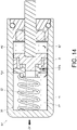
- FIG. 17 is diagram showing a damping device 20d according to a fourth embodiment of the present invention.
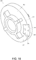
- FIG. 18 is a diagram showing a base 300 of the damping device according to the fourth embodiment of the present invention.
- a base 300 of the fourth embodiment has a surface 302, and the surface 302 has at least one recessed part 304.
- the at least one recessed part 304 has an inclined surface 306 inclined relative to the surface 302.
- the inclined surface 306 is extended to a periphery 310 of the base 300, such as an edge.
- the inclined surface 306 has a top part 307 and a bottom part 308.
- the bottom part 308 is arranged at the periphery 310 of the base 300.
- a width W4 of the top part is smaller than a width W5 of the bottom part of the inclined surface 306.
- the surface 302 of the base 300 is configured to face the ring member 26.
- a passage 312 is formed between the ring member 26 and the base 300.
- the at least one recessed part 304 of the base 300 is configured to allow the passage 312 to be formed between the ring member 26 and the base 300.
- the piston rod 30 is connected to the piston 24, and one portion of the piston rod 30 passes through the sleeve member 46 and the cover body 44.
- the piston rod 30 and the piston 24 can be integrally formed; or the piston rod 30 and the piston 24 can be two independent components and connected to each other by a corresponding structure (such as by screwing or engaging) .
- the piston rod 30 and the piston 24 can be made of a metal material.
- the piston 24 can be made of a non-metal material.
- the elastic member 32 is configured to provide an elastic force between the housing 22 and the piston 24. Wherein, the piston 24 can be held at a predetermined position in response to the elastic force of the elastic member 32, in order to allow the portion of the piston rod 30 to stay extending out of the opening 38 of the housing 22.
- the elastic member 32 is arranged in the chamber 36 of the housing 22, and the base 28 abuts against the elastic member 32.
- the housing 22 and the piston 24 can be moved relative to each other.
- the piston rod 30 is fixed (such as being fixed to an object) and a force along the second direction D2 is applied to the housing 22, Lhe housing 22 is moved along the second direction D2, such that the housing 22 and the piston 24 can be moved relative to each other; or, when the housing 22 is fixed (such as being fixed to an object) and a force along the first direction D1 is applied to the piston rod 30, the piston rod 30 is moved along the first direction D1, such that the piston rod 30 and the housing 22 can be moved relative to each other.
- the piston rod 30 is fixed for example.
- the elastic member 32 accumulates an elastic force in response to a movement of the housing 22 and one portion of the damping medium 52 is squeezed to flow toward the opening 38 through the groove 42.
- the damping medium 52 can flow from a first region A1 of the chamber 36 to a second region A2 of the chamber 36 through the groove 42 in order to provide damping effect.
- damping medium 52 flows from the first region A1 to the second region A2 of the chamber 36, at least one portion of the damping medium 52 passes through the passage 312 between the ring member 26 and the base 300 to enter the groove 42 and further flow to the second region A2; or, at least one portion of the damping medium 52 passes through the mounting space S to enter the groove 42 and further flow to the second region A2.
- the ring member 26 can be used to block other flowing paths of the damping medium 52.
- the ring member 26 can be used to block a gap 65 between the base 300 and the inner wall 40, such that the damping medium 52 can flow from the first region A1 to the second region A2 of the chamber 36 through the groove 42 as much as possible.
- the ring member 26 can be made of the flexible material. As such, when the ring member 26 is pushed by the damping medium 52 to abut against the piston 24, the ring member 26 is slightly expanded and deformed in order to block the gap 65 between the base 300 and the inner wall 40.
- the elastic member 32 continues to accumulate the elastic force in response to the movement of the housing 22, and the damping medium 52 further flows from the first region A1 to the second region A2 of the chamber 36 through the groove 42 in order to continue providing the damping effect.
- the groove 42 is arranged along a direction identical to a relative moving direction between the housing 22 and the piston 24.
- the groove 42 is arranged in a longitudinal direction of the housing 22, and the relative moving direction between the housing 22 and the piston 24 is longitudinal.
- the housing 22 when the force along the second direction D2 no longer exists, the housing 22 is moved along the first direction D1 in response to the elastic force provided by the elastic member 32.
- the damping medium 52 flows back from the second region A2 to the first region A1 of the chamber 36 through the groove 42.
- at least one portion of the damping medium 52 can pass through the passage 312 between the ring member 26 and the base 300 to enter the groove 42 and further flow to the first region A1.
- the inclined surface 306 of the recessed part 304 of the base 28 is configured to increase a backflow speed of the damping medium 52.
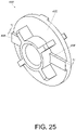
- FIG. 25 is a diagram showing a base 400 of a damping device according to a fifth embodiment of the present invention.
- the base 400 has a surface 402, and at least one rib protruded from the surface 402.
- a first rib 404 and a second rib 406 are shown for example.
- the first rib 404 and the second rib 406 have a height H relative to the surface 402.
- the surface 402 of the base 400 is configured to face the ring member 26, and the ring member 26 is configured to abut against the first rib 404 and the second rib 406 in order to form a passage 408 between the ring member 26 and the surface 402 of the base 400.
- the damping medium 52 flows back from the second region A2 to the first region A1 of the chamber 36 through the groove 42.
- the damping medium 52 can pass through the passage 408 to enter the groove 42 and further flow to the first region A1. Therefore, with one more path provided to allow the damping medium 52 to pass through, the backflow speed of the damping medium 52 can be increased accordingly.
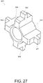
- FIG. 27 is a diagram showing a base 500 of a damping device according to a sixth embodiment of the present invention.
- the base 500 comprises a plurality of protrusions 502.
- a passage 504 is formed between two adjacent protrusions 502.
- the plurality of protrusions 502 are symmetrically arranged, but the present invention is not limited thereto.
- the plurality of protrusions 502 of the base 500 are configured to abut against the ring member 26.
- the damping medium 52 flows back from the second region A2 to the first region A1 of the chamber 36 through the groove 42.
- at least one portion of the damping medium 52 can pass through the passage 504 and directly flows to the first region A1; or, at least one portion of the damping medium 52 can enter the groove 42 and further flow to the first region A1. Therefore, with one more path provided to allow the damping medium 52 to pass through, the backflow speed of the damping medium 52 can be increased accordingly.
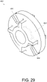
- FIG. 29 is a diagram showing a base 600 of a damping device according to a seventh embodiment of the present invention.
- the base 600 has a surface 602, and at least one recessed part recessed from the surface 602.
- a first recessed part 604 and a second recessed part 606 are recessed from the surface 602 for example.
- the surface 602 of the base 600 is configured to face the ring member 26.
- the first recessed part 604 and the second recessed part 606 are configured to form a passage 608 between the ring member 26 and the base 600.
- the passages are formed by a protruded or recessed structure of the base.
- the surface of the base facing the ring member can be a plane and the ring member 26 has a protruded or recessed structure.
- the passage can also be formed between the surface (the plane) and the ring member 26 in order to allow the damping medium 52 to flow through.
- the damping device 20 is applicable to a furniture hinge 66.
- the damping device 20 can be one of the damping devices 20a to 20g according to the first embodiment to the seventh embodiment.
- the furniture hinge 66 comprises a first component 68 and a second component 70 pivoted to the first component 68.
- the furniture hinge 66 further comprises an auxiliary elastic member (not shown in figures) configured to provide a force when the first component 68 is moved to switch from an open state to a close state relative to the second component 70. (the function of the auxiliary elastic member is well known to those skilled in the art. Therefore, no further illustration is provided.)
- the first component 68 can be mounted to a first furniture part (such as a door).
- the second component 70 can be mounted to a second furniture part (such as a cabinet) through a third component 72.
- the damping device 20 is mounted to one of the first component 68 and the second component 70.
- the first component 68 is a hinge cup
- the second component 70 is a hinge arm
- the damping device 20 is mounted in the hinge cup.
- the piston rod 30 of the damping device 20 abuts against the first component 68
- the housing 22 abuts against the second component 70.
- the housing 22 and the piston 24 can be moved relative to each other for providing damping effect to mitigate movement of closing the first component 68 relative to the second component 70.
- the damping effect provided by the damping device 20 is explained in the above embodiments. For simplification, no further illustration is provided.
Landscapes
- Engineering & Computer Science (AREA)
- General Engineering & Computer Science (AREA)
- Mechanical Engineering (AREA)
- Fluid-Damping Devices (AREA)
Claims (11)
- Dämpfungsvorrichtung (20, 20a, 20b, 20c, 20d, 20e, 20f, 20g), welche umfasst:ein Gehäuse (22) mit einer Innenwand (40), die eine Kammer (36) definiert, und einer Öffnung (38), die mit der Kammer (36) in Verbindung steht, worin die Kammer (36) mit einem Dämpfungsmedium (52) gefüllt ist;eine Deckelanordnung (34), die angrenzend an die Öffnung (38) des Gehäuses (22) angeordnet ist;eine Kolbenstange (30), die durch die Deckelanordnung (34) hindurchgeht;einen Kolben (24), der mit der Kolbenstange (30) verbunden und relativ zu dem Gehäuse (22) beweglich ist, worin der Kolben (24) einen Verlängerungsteil (54) und einen Ausdehnungsteil (56) aufweist, der zwischen der Kolbenstange (30) und dem Verlängerungsteil (54) angeordnet ist, worin eine Breite des Ausdehnungsteils (56) größer als eine Breite der Kolbenstange (30) ist; undein elastisches Element (32), das in der Kammer (36) des Gehäuses (22) angeordnet und ausgestaltet ist, eine elastische Kraft auf den Kolben (24) auszuüben;worin die Innenwand (40) des Gehäuses (22) eine Nut (42) aufweist, die ausgestaltet ist, dass mindestens ein Teil des Dämpfungsmediums (52) hindurchtreten kann, worin die Nut (42) parallel zu einer Längsrichtung des Gehäuses (22) verläuft und ein erstes Ende und ein zweites Ende gegenüber dem ersten Ende aufweist,dadurch gekennzeichnet, dassdie Nut (42) eine konstante Querschnittsfläche vom ersten Ende der Nut (42) bis zum zweiten Ende der Nut (42) aufweist, und das erste Ende der Nut (42) mit einem Ende des Gehäuses (22) verbunden ist, das der Öffnung (38) gegenüberliegt.
- Dämpfungsvorrichtung nach Anspruch 1, ferner dadurch gekennzeichnet, dass zwischen dem Ausdehnungsteil (56) und der Innenwand (40) des Gehäuses (22) ein Spalt (60) ausgebildet ist, der ausgestaltet ist, mindestens ein Teil des Dämpfungsmediums (52) hindurchtreten zu lassen.
- Dämpfungsvorrichtung nach einem der Ansprüche 1 bis 3, gekennzeichnet durch eine Basis (28, 100, 200, 300, 400, 500, 600), die am Kolben (24) und dem Verlängerungsteil (54) benachbart befestigt ist, worin die Basis (28, 100, 200, 300, 400, 500, 600) in der Kammer (36) des Gehäuses (22) angeordnet ist und an dem elastischen Element (32) anliegt.
- Dämpfungsvorrichtung nach Anspruch 3, ferner dadurch gekennzeichnet, dass der Kolben (24) zudem ein Befestigungsteil (58) umfasst, das aus dem Verlängerungsteil (54) herausragt, und dass die Basis (28, 100, 200, 300, 400, 500, 600) an dem Befestigungsteil (58) befestigt ist.
- Dämpfungsvorrichtung nach Anspruch 3 oder 4, ferner dadurch gekennzeichnet, dass die Basis (28) mindestens ein Loch (62) aufweist, das ausgestaltet ist, mindestens ein Teil des Dämpfungsmediums (52) hindurchtreten zu lassen.
- Dämpfungsvorrichtung nach einem der Ansprüche 3 bis 5, ferner gekennzeichnet durch ein Ringelement (26), das bewegbar zwischen dem Ausdehnungsteil (56) des Kolbens (24) und der Basis (28, 100, 200, 300, 400, 500, 600) angebracht ist.
- Dämpfungsvorrichtung nach einem der Ansprüche 1 bis 6, dadurch gekennzeichnet, dass die Kolbenstange (30), das Verlängerungsteil (54) und das Ausdehnungsteil (56) einstückig ausgebildet sind.
- Dämpfungsvorrichtung nach einem der Ansprüche 1 bis 7, dadurch gekennzeichnet, dass eine Breite des Verlängerungsteils (54) größer als die Breite der Kolbenstange (30) und kleiner als die Breite des Ausdehnungsteil (56) ist.
- Dämpfungsvorrichtung nach einem der Ansprüche 1 bis 8, dadurch gekennzeichnet, dass die Kolbenstange (30) und der Kolben (24) aus einem Metallmaterial gefertigt sind.
- Dämpfungsvorrichtung nach einem der Ansprüche 1 bis 9, dadurch gekennzeichnet, dass die Deckelanordnung (34) einen Deckelkörper (44), ein Hülsenelement (46) und einen Dichtungsring (48) umfasst, worin der Deckelkörper (44) einen Raum zur Aufnahme des Hülsenelements (46) bereitstellt, die Kolbenstange (30) durch das Hülsenelement (46) hindurchgeht und der Dichtungsring (48) auf den Deckelkörper (44) aufgeschoben ist.
- Dämpfungsvorrichtung nach Anspruch 1, ferner gekennzeichnet durch:eine Basis (28, 100, 200, 300, 400, 500, 600), die an dem Kolben (24) und benachbart zu dem Verlängerungsteil (54) angebracht ist, worin die Basis (28, 100, 200, 300, 400, 500, 600) in der Kammer (36) des Gehäuses (22) angeordnet ist; undein Ringelement (26), das bewegbar zwischen dem Ausdehnungsteil (56) des Kolbens (24) und dem Boden (28, 100, 200, 300, 400, 500, 600) angebracht ist;worin die Kolbenstange (30), das Verlängerungsteil (54) und das Ausdehnungsteil (56) einstückig ausgebildet sind und ein Spalt (60) zwischen dem Ausdehnungsteil (56) und der Innenwand (40) des Gehäuses (22) ausgebildet ist, um zumindest einen Teil des Dämpfungsmediums (52) hindurchzulassen;wobei, wenn die Kolbenstange (30) durch eine Kraft entlang einer ersten Richtung bewegt wird, das elastische Element (32) eine elastische Kraft akkumuliert und das Ringelement (26) in einer Position relativ zu dem Ausdehnungsteil (56) des Kolbens (24) angeordnet ist, um den Spalt (60) zu blockieren;wobei, wenn die Kraft entlang der ersten Richtung nicht mehr vorliegt, der Kolben (24) entlang einer zweiten Richtung als Reaktion auf die elastische Kraft des elastischen Elements (32) bewegt wird, so dass das Ringelement (26) aus der Position weg bewegt wird, ohne den Spalt (60) zu blockieren.
Applications Claiming Priority (3)
| Application Number | Priority Date | Filing Date | Title |
|---|---|---|---|
| TW105106451A TWI568946B (zh) | 2016-03-02 | 2016-03-02 | 緩衝裝置 |
| TW105115661A TWI573925B (zh) | 2016-05-19 | 2016-05-19 | 傢俱鉸鏈及其阻尼裝置 |
| TW105117121A TWI573924B (zh) | 2016-05-31 | 2016-05-31 | 傢俱鉸鏈及其阻尼裝置 |
Publications (2)
| Publication Number | Publication Date |
|---|---|
| EP3214246A1 EP3214246A1 (de) | 2017-09-06 |
| EP3214246B1 true EP3214246B1 (de) | 2022-09-21 |
Family
ID=57121094
Family Applications (3)
| Application Number | Title | Priority Date | Filing Date |
|---|---|---|---|
| EP16192741.3A Withdrawn EP3214247A1 (de) | 2016-03-02 | 2016-10-07 | Dämpfungsvorrichtung und damit versehenes möbelscharnier |
| EP16192735.5A Active EP3214246B1 (de) | 2016-03-02 | 2016-10-07 | Dämpfungsvorrichtung |
| EP16192745.4A Active EP3214248B1 (de) | 2016-03-02 | 2016-10-07 | Dämpfungsvorrichtung und damit versehenes möbelscharnier |
Family Applications Before (1)
| Application Number | Title | Priority Date | Filing Date |
|---|---|---|---|
| EP16192741.3A Withdrawn EP3214247A1 (de) | 2016-03-02 | 2016-10-07 | Dämpfungsvorrichtung und damit versehenes möbelscharnier |
Family Applications After (1)
| Application Number | Title | Priority Date | Filing Date |
|---|---|---|---|
| EP16192745.4A Active EP3214248B1 (de) | 2016-03-02 | 2016-10-07 | Dämpfungsvorrichtung und damit versehenes möbelscharnier |
Country Status (3)
| Country | Link |
|---|---|
| US (1) | US10145162B2 (de) |
| EP (3) | EP3214247A1 (de) |
| JP (1) | JP6343641B2 (de) |
Families Citing this family (18)
| Publication number | Priority date | Publication date | Assignee | Title |
|---|---|---|---|---|
| US10724284B2 (en) * | 2015-11-03 | 2020-07-28 | Mansfield Engineered Components, Inc. | Appliance lid hinge assembly with snubber |
| US10538950B2 (en) * | 2015-11-05 | 2020-01-21 | Mansfield Engineered Components, Inc. | Lid hinge assembly with snubber and counterbalance spring |
| JP6609045B2 (ja) * | 2017-01-24 | 2019-11-20 | Agc株式会社 | ダンパ装置セット並びに冷蔵及び/又は冷凍用ショーケース |
| US10704311B1 (en) | 2017-02-06 | 2020-07-07 | Mansfield Engineered Components, Inc. | Appliance lid hinge |
| JP2019036777A (ja) | 2017-08-10 | 2019-03-07 | シャープ株式会社 | 基地局装置および端末装置 |
| TWI641342B (zh) * | 2017-11-06 | 2018-11-21 | King Slide Works Co., Ltd. | 緩衝裝置及包含有該緩衝裝置的傢俱件 |
| TWI645811B (zh) | 2017-11-06 | 2019-01-01 | 川湖科技股份有限公司 | 可活動傢俱件及其緩衝裝置 |
| US11866977B2 (en) | 2018-07-06 | 2024-01-09 | Moshun, LLC | Systems and devices for adjustable door closure control |
| EP3667007B1 (de) * | 2018-12-13 | 2023-08-02 | Apparatebau Gronbach Srl | Dämpfer, insbesondere für ein scharnier, sowie scharnier, insbesondere für ein haushaltsgerät, und haushaltsgerät |
| GB2590978A (en) * | 2020-01-13 | 2021-07-14 | Titus D O O Dekani | Improvements in Dampers |
| AT523986B1 (de) * | 2020-07-13 | 2023-05-15 | Blum Gmbh Julius | Möbeldämpfer |
| US11867252B2 (en) | 2021-01-08 | 2024-01-09 | Moshun, LLC | Systems and devices for motion control |
| AT525400A1 (de) * | 2021-08-20 | 2023-03-15 | Blum Gmbh Julius | Dämpfer |
| EP4460647A4 (de) * | 2021-12-01 | 2025-12-03 | Samet Kalip Ve Madeni Esya San Ve Tic A S | Hydraulischer dämpfer für möbeltüren und schubladen |
| US12473768B2 (en) | 2022-03-23 | 2025-11-18 | Moshun, LLC | Systems and devices for motion control |
| CN116221262B (zh) * | 2022-11-15 | 2024-05-31 | 青岛大学 | 阻尼连接器 |
| EP4450744A3 (de) * | 2023-04-20 | 2024-12-04 | LG Electronics Inc. | Kühlschrank |
| CN119332557A (zh) * | 2024-12-19 | 2025-01-21 | 甘肃省地震局(中国地震局兰州地震研究所) | 一种穿越活动逆断层的路基抗断装置及应用方法 |
Citations (3)
| Publication number | Priority date | Publication date | Assignee | Title |
|---|---|---|---|---|
| US1744514A (en) * | 1928-08-28 | 1930-01-21 | Clarance W Thompson | Hydraulic valve |
| DE202009004752U1 (de) * | 2009-04-28 | 2010-09-09 | Druck- und Spritzgußwerk Hettich GmbH & Co. KG | Dämpfer für Möbel |
| DE202016100176U1 (de) * | 2015-01-19 | 2016-02-01 | Julius Blum Gmbh | Möbeldämpfer |
Family Cites Families (20)
| Publication number | Priority date | Publication date | Assignee | Title |
|---|---|---|---|---|
| DE20221550U1 (de) * | 1977-02-03 | 2006-05-11 | Julius Blum Gmbh | Fluiddämpfer, insbesondere für bewegliche Möbelteile |
| JPS56101439A (en) | 1980-01-10 | 1981-08-14 | Itsuki Ban | Late moving device utilizing liquid |
| US5579874A (en) | 1994-09-13 | 1996-12-03 | Avm, Inc. | Adjustable speed gas spring |
| GB2303193B (en) * | 1995-07-13 | 1998-10-14 | Draftex Ind Ltd | Gas spring |
| JPH10331517A (ja) | 1997-05-30 | 1998-12-15 | Yagi:Kk | 開閉調整器 |
| DE10313659B3 (de) * | 2003-03-26 | 2004-09-30 | Zimmer, Günther Stephan | Pneumatische Verzögerungsvorrichtung zum Abbremsen beweglicher Möbelteile |
| JP4859066B2 (ja) | 2007-12-01 | 2012-01-18 | 共栄工業株式会社 | 流体ダンパ |
| JP4755208B2 (ja) | 2008-01-21 | 2011-08-24 | 株式会社ベスト | 自閉式引戸装置 |
| WO2009094272A1 (en) | 2008-01-22 | 2009-07-30 | Grass America, Inc. | Damping mechanism for cabinet hinge assembly |
| AT508068B1 (de) | 2009-03-25 | 2016-11-15 | Blum Gmbh Julius | Möbelscharnier |
| DE202009006233U1 (de) | 2009-04-30 | 2010-09-23 | Lautenschläger, Horst | Dämpferzylinder für eine Dämpfungseinrichtung für Möbel |
| DE102010022052A1 (de) | 2009-12-01 | 2011-06-09 | Dorma Gmbh + Co. Kg | Hydraulisches Magnetwegeventil und Türschließer mit hydraulischem Magnetwegeventil |
| EP2546443A1 (de) | 2010-03-12 | 2013-01-16 | Moonju Hardware Co., Ltd. | Türdämpfer |
| AT509720B1 (de) | 2010-08-23 | 2011-11-15 | Blum Gmbh Julius | Dämpfvorrichtung für möbelteile |
| AT510375B1 (de) | 2010-08-27 | 2018-06-15 | Blum Gmbh Julius | Möbeldämpfer |
| ITMI20121122A1 (it) | 2012-06-26 | 2013-12-27 | Salice Arturo Spa | Cerniera decelerata per mobili |
| ITMI20121837A1 (it) | 2012-10-29 | 2014-04-30 | Salice Arturo Spa | Cerniera per mobili con dispositivo di decelerazione disattivabile |
| GB2513848A (en) * | 2013-05-03 | 2014-11-12 | Lama D D Dekani | Improvements in damper assemblies |
| CN203308270U (zh) | 2013-06-04 | 2013-11-27 | 广东泰明金属制品有限公司 | 家具铰链的阻尼器装置 |
| ITMI20131542A1 (it) | 2013-09-19 | 2015-03-20 | Salice Arturo Spa | Cerniera decelerata per mobili |
-
2016
- 2016-08-30 US US15/252,183 patent/US10145162B2/en active Active
- 2016-10-05 JP JP2016197045A patent/JP6343641B2/ja active Active
- 2016-10-07 EP EP16192741.3A patent/EP3214247A1/de not_active Withdrawn
- 2016-10-07 EP EP16192735.5A patent/EP3214246B1/de active Active
- 2016-10-07 EP EP16192745.4A patent/EP3214248B1/de active Active
Patent Citations (3)
| Publication number | Priority date | Publication date | Assignee | Title |
|---|---|---|---|---|
| US1744514A (en) * | 1928-08-28 | 1930-01-21 | Clarance W Thompson | Hydraulic valve |
| DE202009004752U1 (de) * | 2009-04-28 | 2010-09-09 | Druck- und Spritzgußwerk Hettich GmbH & Co. KG | Dämpfer für Möbel |
| DE202016100176U1 (de) * | 2015-01-19 | 2016-02-01 | Julius Blum Gmbh | Möbeldämpfer |
Also Published As
| Publication number | Publication date |
|---|---|
| EP3214248B1 (de) | 2022-09-21 |
| JP2017155578A (ja) | 2017-09-07 |
| US20170254133A1 (en) | 2017-09-07 |
| EP3214246A1 (de) | 2017-09-06 |
| EP3214248A1 (de) | 2017-09-06 |
| US10145162B2 (en) | 2018-12-04 |
| EP3214247A1 (de) | 2017-09-06 |
| JP6343641B2 (ja) | 2018-06-13 |
Similar Documents
| Publication | Publication Date | Title |
|---|---|---|
| EP3214246B1 (de) | Dämpfungsvorrichtung | |
| JP5270376B2 (ja) | 家具用のダンパ | |
| US8925151B2 (en) | Decelerated hinge for furniture | |
| EP3480401B1 (de) | Möbelteil und dämpfungsvorrichtung dafür | |
| EP3480400B1 (de) | Dämpfungsvorrichtung und möbelteil damit | |
| TWI573924B (zh) | 傢俱鉸鏈及其阻尼裝置 | |
| WO2015185462A1 (en) | Damper assembly for providing different damping effects at different parts of the stroke | |
| CN107165967B (zh) | 缓冲装置 | |
| EP2841791B1 (de) | Verbesserungen bei dämpfern | |
| JP2012031887A (ja) | ダンパー | |
| CN107461103A (zh) | 家具铰链及其阻尼装置 | |
| KR101986716B1 (ko) | 문 열림 완충장치 | |
| TWI573925B (zh) | 傢俱鉸鏈及其阻尼裝置 | |
| KR101986715B1 (ko) | 문 닫힘 완충장치 | |
| KR101534156B1 (ko) | 완충용 도어 댐퍼 | |
| KR101891372B1 (ko) | 댐퍼 장치 | |
| EP1778049A1 (de) | Türdämpfer | |
| CN107476697A (zh) | 家具铰链及其阻尼装置 | |
| CN111485783A (zh) | 缓冲装置 | |
| EP2775163A1 (de) | Flüssigkeitsstoßdämpfer, insbesondere für Türen von elektrischen Haushaltsgeräten | |
| JP5322678B2 (ja) | ショックアブソーバ | |
| TW202028593A (zh) | 緩衝裝置 | |
| KR20030062834A (ko) | 도어용 완충장치 | |
| KR20170001414U (ko) | 가구 힌지용 어댑터 |
Legal Events
| Date | Code | Title | Description |
|---|---|---|---|
| PUAI | Public reference made under article 153(3) epc to a published international application that has entered the european phase |
Free format text: ORIGINAL CODE: 0009012 |
|
| STAA | Information on the status of an ep patent application or granted ep patent |
Free format text: STATUS: THE APPLICATION HAS BEEN PUBLISHED |
|
| AK | Designated contracting states |
Kind code of ref document: A1 Designated state(s): AL AT BE BG CH CY CZ DE DK EE ES FI FR GB GR HR HU IE IS IT LI LT LU LV MC MK MT NL NO PL PT RO RS SE SI SK SM TR |
|
| AX | Request for extension of the european patent |
Extension state: BA ME |
|
| STAA | Information on the status of an ep patent application or granted ep patent |
Free format text: STATUS: REQUEST FOR EXAMINATION WAS MADE |
|
| 17P | Request for examination filed |
Effective date: 20180226 |
|
| RBV | Designated contracting states (corrected) |
Designated state(s): AL AT BE BG CH CY CZ DE DK EE ES FI FR GB GR HR HU IE IS IT LI LT LU LV MC MK MT NL NO PL PT RO RS SE SI SK SM TR |
|
| STAA | Information on the status of an ep patent application or granted ep patent |
Free format text: STATUS: EXAMINATION IS IN PROGRESS |
|
| 17Q | First examination report despatched |
Effective date: 20191001 |
|
| GRAP | Despatch of communication of intention to grant a patent |
Free format text: ORIGINAL CODE: EPIDOSNIGR1 |
|
| STAA | Information on the status of an ep patent application or granted ep patent |
Free format text: STATUS: GRANT OF PATENT IS INTENDED |
|
| INTG | Intention to grant announced |
Effective date: 20220513 |
|
| RAP3 | Party data changed (applicant data changed or rights of an application transferred) |
Owner name: KING SLIDE TECHNOLOGY CO., LTD. Owner name: KING SLIDE WORKS CO., LTD. |
|
| RIN1 | Information on inventor provided before grant (corrected) |
Inventor name: WANG, CHUN-CHIANG Inventor name: CHEN, KEN-CHING Inventor name: LIANG, HSIU-CHIANG |
|
| GRAS | Grant fee paid |
Free format text: ORIGINAL CODE: EPIDOSNIGR3 |
|
| GRAA | (expected) grant |
Free format text: ORIGINAL CODE: 0009210 |
|
| STAA | Information on the status of an ep patent application or granted ep patent |
Free format text: STATUS: THE PATENT HAS BEEN GRANTED |
|
| AK | Designated contracting states |
Kind code of ref document: B1 Designated state(s): AL AT BE BG CH CY CZ DE DK EE ES FI FR GB GR HR HU IE IS IT LI LT LU LV MC MK MT NL NO PL PT RO RS SE SI SK SM TR |
|
| REG | Reference to a national code |
Ref country code: GB Ref legal event code: FG4D |
|
| REG | Reference to a national code |
Ref country code: CH Ref legal event code: EP |
|
| REG | Reference to a national code |
Ref country code: IE Ref legal event code: FG4D |
|
| REG | Reference to a national code |
Ref country code: DE Ref legal event code: R096 Ref document number: 602016075119 Country of ref document: DE |
|
| REG | Reference to a national code |
Ref country code: AT Ref legal event code: REF Ref document number: 1520034 Country of ref document: AT Kind code of ref document: T Effective date: 20221015 |
|
| REG | Reference to a national code |
Ref country code: LT Ref legal event code: MG9D |
|
| REG | Reference to a national code |
Ref country code: NL Ref legal event code: MP Effective date: 20220921 |
|
| PG25 | Lapsed in a contracting state [announced via postgrant information from national office to epo] |
Ref country code: SE Free format text: LAPSE BECAUSE OF FAILURE TO SUBMIT A TRANSLATION OF THE DESCRIPTION OR TO PAY THE FEE WITHIN THE PRESCRIBED TIME-LIMIT Effective date: 20220921 Ref country code: RS Free format text: LAPSE BECAUSE OF FAILURE TO SUBMIT A TRANSLATION OF THE DESCRIPTION OR TO PAY THE FEE WITHIN THE PRESCRIBED TIME-LIMIT Effective date: 20220921 Ref country code: NO Free format text: LAPSE BECAUSE OF FAILURE TO SUBMIT A TRANSLATION OF THE DESCRIPTION OR TO PAY THE FEE WITHIN THE PRESCRIBED TIME-LIMIT Effective date: 20221221 Ref country code: LV Free format text: LAPSE BECAUSE OF FAILURE TO SUBMIT A TRANSLATION OF THE DESCRIPTION OR TO PAY THE FEE WITHIN THE PRESCRIBED TIME-LIMIT Effective date: 20220921 Ref country code: LT Free format text: LAPSE BECAUSE OF FAILURE TO SUBMIT A TRANSLATION OF THE DESCRIPTION OR TO PAY THE FEE WITHIN THE PRESCRIBED TIME-LIMIT Effective date: 20220921 Ref country code: FI Free format text: LAPSE BECAUSE OF FAILURE TO SUBMIT A TRANSLATION OF THE DESCRIPTION OR TO PAY THE FEE WITHIN THE PRESCRIBED TIME-LIMIT Effective date: 20220921 |
|
| REG | Reference to a national code |
Ref country code: AT Ref legal event code: MK05 Ref document number: 1520034 Country of ref document: AT Kind code of ref document: T Effective date: 20220921 |
|
| PG25 | Lapsed in a contracting state [announced via postgrant information from national office to epo] |
Ref country code: HR Free format text: LAPSE BECAUSE OF FAILURE TO SUBMIT A TRANSLATION OF THE DESCRIPTION OR TO PAY THE FEE WITHIN THE PRESCRIBED TIME-LIMIT Effective date: 20220921 Ref country code: GR Free format text: LAPSE BECAUSE OF FAILURE TO SUBMIT A TRANSLATION OF THE DESCRIPTION OR TO PAY THE FEE WITHIN THE PRESCRIBED TIME-LIMIT Effective date: 20221222 |
|
| PG25 | Lapsed in a contracting state [announced via postgrant information from national office to epo] |
Ref country code: SM Free format text: LAPSE BECAUSE OF FAILURE TO SUBMIT A TRANSLATION OF THE DESCRIPTION OR TO PAY THE FEE WITHIN THE PRESCRIBED TIME-LIMIT Effective date: 20220921 Ref country code: RO Free format text: LAPSE BECAUSE OF FAILURE TO SUBMIT A TRANSLATION OF THE DESCRIPTION OR TO PAY THE FEE WITHIN THE PRESCRIBED TIME-LIMIT Effective date: 20220921 Ref country code: PT Free format text: LAPSE BECAUSE OF FAILURE TO SUBMIT A TRANSLATION OF THE DESCRIPTION OR TO PAY THE FEE WITHIN THE PRESCRIBED TIME-LIMIT Effective date: 20230123 Ref country code: ES Free format text: LAPSE BECAUSE OF FAILURE TO SUBMIT A TRANSLATION OF THE DESCRIPTION OR TO PAY THE FEE WITHIN THE PRESCRIBED TIME-LIMIT Effective date: 20220921 Ref country code: CZ Free format text: LAPSE BECAUSE OF FAILURE TO SUBMIT A TRANSLATION OF THE DESCRIPTION OR TO PAY THE FEE WITHIN THE PRESCRIBED TIME-LIMIT Effective date: 20220921 Ref country code: AT Free format text: LAPSE BECAUSE OF FAILURE TO SUBMIT A TRANSLATION OF THE DESCRIPTION OR TO PAY THE FEE WITHIN THE PRESCRIBED TIME-LIMIT Effective date: 20220921 |
|
| PG25 | Lapsed in a contracting state [announced via postgrant information from national office to epo] |
Ref country code: SK Free format text: LAPSE BECAUSE OF FAILURE TO SUBMIT A TRANSLATION OF THE DESCRIPTION OR TO PAY THE FEE WITHIN THE PRESCRIBED TIME-LIMIT Effective date: 20220921 Ref country code: PL Free format text: LAPSE BECAUSE OF FAILURE TO SUBMIT A TRANSLATION OF THE DESCRIPTION OR TO PAY THE FEE WITHIN THE PRESCRIBED TIME-LIMIT Effective date: 20220921 Ref country code: IS Free format text: LAPSE BECAUSE OF FAILURE TO SUBMIT A TRANSLATION OF THE DESCRIPTION OR TO PAY THE FEE WITHIN THE PRESCRIBED TIME-LIMIT Effective date: 20230121 Ref country code: EE Free format text: LAPSE BECAUSE OF FAILURE TO SUBMIT A TRANSLATION OF THE DESCRIPTION OR TO PAY THE FEE WITHIN THE PRESCRIBED TIME-LIMIT Effective date: 20220921 |
|
| REG | Reference to a national code |
Ref country code: CH Ref legal event code: PL |
|
| REG | Reference to a national code |
Ref country code: DE Ref legal event code: R097 Ref document number: 602016075119 Country of ref document: DE |
|
| REG | Reference to a national code |
Ref country code: BE Ref legal event code: MM Effective date: 20221031 |
|
| PG25 | Lapsed in a contracting state [announced via postgrant information from national office to epo] |
Ref country code: NL Free format text: LAPSE BECAUSE OF FAILURE TO SUBMIT A TRANSLATION OF THE DESCRIPTION OR TO PAY THE FEE WITHIN THE PRESCRIBED TIME-LIMIT Effective date: 20220921 Ref country code: MC Free format text: LAPSE BECAUSE OF FAILURE TO SUBMIT A TRANSLATION OF THE DESCRIPTION OR TO PAY THE FEE WITHIN THE PRESCRIBED TIME-LIMIT Effective date: 20220921 Ref country code: LU Free format text: LAPSE BECAUSE OF NON-PAYMENT OF DUE FEES Effective date: 20221007 Ref country code: AL Free format text: LAPSE BECAUSE OF FAILURE TO SUBMIT A TRANSLATION OF THE DESCRIPTION OR TO PAY THE FEE WITHIN THE PRESCRIBED TIME-LIMIT Effective date: 20220921 |
|
| PLBE | No opposition filed within time limit |
Free format text: ORIGINAL CODE: 0009261 |
|
| STAA | Information on the status of an ep patent application or granted ep patent |
Free format text: STATUS: NO OPPOSITION FILED WITHIN TIME LIMIT |
|
| PG25 | Lapsed in a contracting state [announced via postgrant information from national office to epo] |
Ref country code: LI Free format text: LAPSE BECAUSE OF NON-PAYMENT OF DUE FEES Effective date: 20221031 Ref country code: DK Free format text: LAPSE BECAUSE OF FAILURE TO SUBMIT A TRANSLATION OF THE DESCRIPTION OR TO PAY THE FEE WITHIN THE PRESCRIBED TIME-LIMIT Effective date: 20220921 Ref country code: CH Free format text: LAPSE BECAUSE OF NON-PAYMENT OF DUE FEES Effective date: 20221031 |
|
| 26N | No opposition filed |
Effective date: 20230622 |
|
| PG25 | Lapsed in a contracting state [announced via postgrant information from national office to epo] |
Ref country code: SI Free format text: LAPSE BECAUSE OF FAILURE TO SUBMIT A TRANSLATION OF THE DESCRIPTION OR TO PAY THE FEE WITHIN THE PRESCRIBED TIME-LIMIT Effective date: 20220921 |
|
| PG25 | Lapsed in a contracting state [announced via postgrant information from national office to epo] |
Ref country code: BE Free format text: LAPSE BECAUSE OF NON-PAYMENT OF DUE FEES Effective date: 20221031 |
|
| PG25 | Lapsed in a contracting state [announced via postgrant information from national office to epo] |
Ref country code: FR Free format text: LAPSE BECAUSE OF NON-PAYMENT OF DUE FEES Effective date: 20221121 |
|
| PG25 | Lapsed in a contracting state [announced via postgrant information from national office to epo] |
Ref country code: HU Free format text: LAPSE BECAUSE OF FAILURE TO SUBMIT A TRANSLATION OF THE DESCRIPTION OR TO PAY THE FEE WITHIN THE PRESCRIBED TIME-LIMIT; INVALID AB INITIO Effective date: 20161007 |
|
| PG25 | Lapsed in a contracting state [announced via postgrant information from national office to epo] |
Ref country code: CY Free format text: LAPSE BECAUSE OF FAILURE TO SUBMIT A TRANSLATION OF THE DESCRIPTION OR TO PAY THE FEE WITHIN THE PRESCRIBED TIME-LIMIT Effective date: 20220921 |
|
| PG25 | Lapsed in a contracting state [announced via postgrant information from national office to epo] |
Ref country code: MK Free format text: LAPSE BECAUSE OF FAILURE TO SUBMIT A TRANSLATION OF THE DESCRIPTION OR TO PAY THE FEE WITHIN THE PRESCRIBED TIME-LIMIT Effective date: 20220921 Ref country code: IT Free format text: LAPSE BECAUSE OF FAILURE TO SUBMIT A TRANSLATION OF THE DESCRIPTION OR TO PAY THE FEE WITHIN THE PRESCRIBED TIME-LIMIT Effective date: 20220921 |
|
| PG25 | Lapsed in a contracting state [announced via postgrant information from national office to epo] |
Ref country code: BG Free format text: LAPSE BECAUSE OF FAILURE TO SUBMIT A TRANSLATION OF THE DESCRIPTION OR TO PAY THE FEE WITHIN THE PRESCRIBED TIME-LIMIT Effective date: 20220921 |
|
| REG | Reference to a national code |
Ref country code: DE Ref legal event code: R082 Ref document number: 602016075119 Country of ref document: DE Representative=s name: STRAUS, ALEXANDER, DIPL.-CHEM.UNIV. DR.PHIL., DE |
|
| PG25 | Lapsed in a contracting state [announced via postgrant information from national office to epo] |
Ref country code: MT Free format text: LAPSE BECAUSE OF FAILURE TO SUBMIT A TRANSLATION OF THE DESCRIPTION OR TO PAY THE FEE WITHIN THE PRESCRIBED TIME-LIMIT Effective date: 20220921 |
|
| PGFP | Annual fee paid to national office [announced via postgrant information from national office to epo] |
Ref country code: IE Payment date: 20250609 Year of fee payment: 10 |
|
| PGFP | Annual fee paid to national office [announced via postgrant information from national office to epo] |
Ref country code: GB Payment date: 20250805 Year of fee payment: 10 |
|
| PG25 | Lapsed in a contracting state [announced via postgrant information from national office to epo] |
Ref country code: TR Free format text: LAPSE BECAUSE OF FAILURE TO SUBMIT A TRANSLATION OF THE DESCRIPTION OR TO PAY THE FEE WITHIN THE PRESCRIBED TIME-LIMIT Effective date: 20220921 |
|
| PGFP | Annual fee paid to national office [announced via postgrant information from national office to epo] |
Ref country code: DE Payment date: 20250611 Year of fee payment: 10 |