EP3214293A1 - Verfahren und vorrichtung zur berechnung einer luftmenge in einem fahrzeugmotor-ansaugrohr, und entsprechendes fahrzeug - Google Patents
Verfahren und vorrichtung zur berechnung einer luftmenge in einem fahrzeugmotor-ansaugrohr, und entsprechendes fahrzeug Download PDFInfo
- Publication number
- EP3214293A1 EP3214293A1 EP17157675.4A EP17157675A EP3214293A1 EP 3214293 A1 EP3214293 A1 EP 3214293A1 EP 17157675 A EP17157675 A EP 17157675A EP 3214293 A1 EP3214293 A1 EP 3214293A1
- Authority
- EP
- European Patent Office
- Prior art keywords
- atmospheric pressure
- calculating
- vehicle
- manifold
- longitudinal
- Prior art date
- Legal status (The legal status is an assumption and is not a legal conclusion. Google has not performed a legal analysis and makes no representation as to the accuracy of the status listed.)
- Withdrawn
Links
- 238000000034 method Methods 0.000 title claims abstract description 30
- 230000001133 acceleration Effects 0.000 claims abstract description 16
- 238000011144 upstream manufacturing Methods 0.000 claims abstract description 9
- 238000009530 blood pressure measurement Methods 0.000 claims abstract description 4
- 238000009529 body temperature measurement Methods 0.000 claims abstract description 4
- 238000004364 calculation method Methods 0.000 claims description 26
- 230000001427 coherent effect Effects 0.000 claims description 4
- 230000010354 integration Effects 0.000 claims description 4
- 238000009795 derivation Methods 0.000 claims description 2
- 239000000446 fuel Substances 0.000 description 10
- 239000000203 mixture Substances 0.000 description 4
- 239000007789 gas Substances 0.000 description 3
- 230000005484 gravity Effects 0.000 description 3
- 238000002485 combustion reaction Methods 0.000 description 2
- 238000010586 diagram Methods 0.000 description 2
- 238000006073 displacement reaction Methods 0.000 description 2
- 230000002706 hydrostatic effect Effects 0.000 description 2
- 238000002347 injection Methods 0.000 description 2
- 239000007924 injection Substances 0.000 description 2
- 238000005259 measurement Methods 0.000 description 2
- 101100492805 Caenorhabditis elegans atm-1 gene Proteins 0.000 description 1
- 230000001594 aberrant effect Effects 0.000 description 1
- 238000006243 chemical reaction Methods 0.000 description 1
- 230000009194 climbing Effects 0.000 description 1
- 239000003344 environmental pollutant Substances 0.000 description 1
- 231100000719 pollutant Toxicity 0.000 description 1
- 239000000243 solution Substances 0.000 description 1
- 238000012795 verification Methods 0.000 description 1
Images


Classifications
-
- F—MECHANICAL ENGINEERING; LIGHTING; HEATING; WEAPONS; BLASTING
- F02—COMBUSTION ENGINES; HOT-GAS OR COMBUSTION-PRODUCT ENGINE PLANTS
- F02D—CONTROLLING COMBUSTION ENGINES
- F02D41/00—Electrical control of supply of combustible mixture or its constituents
- F02D41/02—Circuit arrangements for generating control signals
- F02D41/18—Circuit arrangements for generating control signals by measuring intake air flow
-
- F—MECHANICAL ENGINEERING; LIGHTING; HEATING; WEAPONS; BLASTING
- F02—COMBUSTION ENGINES; HOT-GAS OR COMBUSTION-PRODUCT ENGINE PLANTS
- F02D—CONTROLLING COMBUSTION ENGINES
- F02D2200/00—Input parameters for engine control
- F02D2200/02—Input parameters for engine control the parameters being related to the engine
- F02D2200/04—Engine intake system parameters
- F02D2200/0402—Engine intake system parameters the parameter being determined by using a model of the engine intake or its components
-
- F—MECHANICAL ENGINEERING; LIGHTING; HEATING; WEAPONS; BLASTING
- F02—COMBUSTION ENGINES; HOT-GAS OR COMBUSTION-PRODUCT ENGINE PLANTS
- F02D—CONTROLLING COMBUSTION ENGINES
- F02D2200/00—Input parameters for engine control
- F02D2200/50—Input parameters for engine control said parameters being related to the vehicle or its components
- F02D2200/501—Vehicle speed
-
- F—MECHANICAL ENGINEERING; LIGHTING; HEATING; WEAPONS; BLASTING
- F02—COMBUSTION ENGINES; HOT-GAS OR COMBUSTION-PRODUCT ENGINE PLANTS
- F02D—CONTROLLING COMBUSTION ENGINES
- F02D2200/00—Input parameters for engine control
- F02D2200/70—Input parameters for engine control said parameters being related to the vehicle exterior
- F02D2200/702—Road conditions
-
- F—MECHANICAL ENGINEERING; LIGHTING; HEATING; WEAPONS; BLASTING
- F02—COMBUSTION ENGINES; HOT-GAS OR COMBUSTION-PRODUCT ENGINE PLANTS
- F02D—CONTROLLING COMBUSTION ENGINES
- F02D2200/00—Input parameters for engine control
- F02D2200/70—Input parameters for engine control said parameters being related to the vehicle exterior
- F02D2200/703—Atmospheric pressure
- F02D2200/704—Estimation of atmospheric pressure
Definitions
- the invention relates to the field of controlling the air-fuel mixture in combustion engines. It relates more particularly to a method of calculating a quantity of air in a vehicle manifold, a corresponding device and a vehicle equipped with such a device.
- Gasoline-powered vehicles are conventionally equipped with an air-fuel mixture control device intended to guarantee an air-fuel mixture in the most often stoichiometric proportions, in order to obtain good combustion.
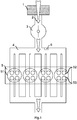
- the figure 1 represents a schematic and partial view of the architecture of a gasoline engine equipping a motor vehicle.
- the engine 5 shown comprises four cylinders 51 each equipped with four valves, two intake valves 52 and two exhaust valves 53.
- the intake valves 52 are supplied with air by a distributor 4, or intake manifold 4.
- the fresh air arrives in the manifold 4 after passing in order an air filter 1 and a throttle body 3.
- the air flow is represented by arrows 2.
- the amount of air present in the manifold 4 is determined, and then the amount of fuel to be injected into each cylinder is calculated based on the amount of air previously determined.
- the quantity of air is generally determined by the Barré Saint-Venant formula, which makes it possible to calculate a mass flow rate of air as a function of the atmospheric pressure, the pressure in the collector, the atmospheric temperature and the effective cross-section. Butterfly housing. This formula is detailed later.
- a pressure sensor 6 is used for cost issues. The latter is placed in the collector as shown in figure 1 . The pressure sensor 6 thus makes it possible to know the pressure that prevails in the collector 4 at any moment. It also allows for an ad hoc estimate of the atmospheric pressure.
- the injection of fuel is cut off and the throttle body 3 is wide open, so that the pressure of the manifold, that is to say the pressure downstream of the throttle body 3, is very substantially equal to the atmospheric pressure, that is to say ie the pressure upstream of the throttle body 3.
- the pressure then measured by the pressure sensor 6 is stored as the reference atmospheric pressure value.
- the reference atmospheric pressure value gives satisfactory results in the presence of small variations of altitudes because the atmospheric pressure depends essentially on altitude.
- the reference atmospheric pressure stored can become very far from the real atmospheric pressure if the driver of the vehicle does not lift any feet, for example if constantly maintain a press on the accelerator pedal in order to produce the necessary torque to climb an uninterrupted slope, and the calculated air mass flow rate is then increasingly wrong as the slope is climbed. Therefore, fuel injected based on this false air flow calculation is not in stoichiometric proportions, which results in performance, fuel consumption and pollutant problems.
- An object of the invention is to allow the calculation of an amount of air in a vehicle engine intake manifold in the absence of atmospheric pressure sensor while taking into account rapid and significant changes in altitude.
- the invention relates to a method for calculating an amount of air in a motor vehicle engine intake manifold, the vehicle being equipped with a throttle body located upstream of the manifold, a pressure sensor in the collector, an external temperature sensor, an accelerometer measuring values of longitudinal acceleration of the vehicle, a device for measuring the longitudinal speed of the vehicle, the method being characterized in that it comprises a calculation step an atmospheric pressure from a longitudinal acceleration provided by the accelerometer and at least two longitudinal speeds provided by the speed measuring device; and a step of calculating an amount of air in the collector from a section value effective throttle valve, a pressure measurement in the manifold by the pressure sensor in the manifold, an outdoor temperature measurement by the outdoor temperature sensor and the atmospheric pressure calculated in the calculation step of atmospheric pressure.
- the method has the advantage of calculating an air flow rate as a function of atmospheric pressure recalculated at each instant so as to guarantee a good estimate of the air flow rate and therefore of the quantity of fuel to be injected in order to obtain an air mixture. -carburting in stoichiometric proportions.
- Longitudinal direction means the direction of movement of the vehicle.
- the step of calculating an atmospheric pressure comprises the following intermediate steps: calculating a current altitude from the longitudinal acceleration provided by the accelerometer and at least two longitudinal speeds provided by the speed measuring device; and calculating the atmospheric pressure from the current altitude determined in the intermediate step of calculating a current altitude.
- the method has the advantage of taking into account the variation of atmospheric pressure with altitude.
- the intermediate step of calculating a current altitude comprises the following basic steps: calculating a slope traveled by the vehicle from the longitudinal acceleration provided by the accelerometer and the derivation of the longitudinal speeds provided by the speed measuring device; and calculating the current altitude from the integration of the product of the longitudinal velocity by the slope calculated at the elementary stage calculation of a slope.
- the method has the advantage of calculating the current altitude using elements present by default in the vehicle, which makes it possible to limit the costs associated with this new estimation of the atmospheric pressure.
- the method further comprises an initialization step before the step of calculating an atmospheric pressure of storing a reference atmospheric pressure value measured by the pressure sensor in the collector each time. that the driver of the vehicle performs a foot lift resulting in a complete opening of the throttle body.
- This step of initialization of the atmospheric pressure makes it possible to limit the drifts of the computation during the successive iterations of the process and thus guarantees a better accuracy of the computations.
- the method further comprises a preliminary step before the step of calculating an atmospheric pressure of storing a reference outdoor temperature value measured by the outdoor temperature sensor. This step also guarantees better calculation accuracy.
- the method further comprises a step of storing the value of the atmospheric pressure calculated at the step of calculating the atmospheric pressure after the step of calculating the atmospheric pressure.
- the storage of the atmospheric pressure value makes it possible to use the atmospheric pressure value later, as part of the calculation of a mass flow of air in the collector or for other uses.
- the method further comprises a step of verifying consistency of the value of the atmospheric pressure calculated at the step of calculating the atmospheric pressure with respect to a range of coherent atmospheric pressures.
- the verification of the coherence of the atmospheric pressure value makes it possible to limit the error introduced in calculations using atmospheric pressure. In particular, it avoids injecting a quantity of aberrant fuel into the engine.
- the step of calculating an amount of air uses as atmospheric pressure value the atmospheric pressure calculated at the step of calculating an atmospheric pressure if the pressure is coherent and the pressure value previous atmospheric otherwise. Keeping the previous atmospheric pressure value in the case of an incoherent atmospheric pressure value makes it possible to use a value that is relatively close to the actual atmospheric pressure value despite an error in the calculation of this value.
- the invention also relates to a device for calculating an amount of air in a motor vehicle engine intake manifold, the vehicle being equipped with a throttle body located upstream of the manifold, the device comprising a pressure sensor in the collector, an external temperature sensor, an accelerometer measuring values of longitudinal acceleration of the vehicle, a device for measuring the longitudinal speed of the vehicle, the device being characterized in that it further comprises a computing unit capable of implement the method of the invention.
- the invention also relates to a motor vehicle equipped with a throttle body located upstream of a intake manifold, the vehicle being characterized in that it comprises said device.
- a flowchart according to the method of calculating an amount of air in a motor vehicle collector.
- the method is intended to be implemented in a vehicle equipped with a motor provided with an intake manifold 4, a throttle body 3 located upstream of the manifold 4, a pressure sensor 6 capable of measuring the pressure in the manifold, an outdoor temperature sensor, an accelerometer measuring values of longitudinal acceleration of the vehicle and a device for measuring longitudinal velocity of the vehicle.
- Steps E1 and E2 are optional. They are described later.
- Step E3 itself comprises a slope calculation step E31, an altitude calculation step E32 starting from the slope and a step E33 of calculating atmospheric pressure from the result of the preceding step.
- the figure 3 represents a vehicle 8 climbing a slope of angle ⁇ in a reference of vertical axis Z, the vertical direction being defined by gravity, and of horizontal axis X, the horizontal direction being defined as being perpendicular to the Z axis on the figure.
- the car advances in the direction of the slope at a longitudinal velocity V vehicle calculated by the longitudinal velocity measuring device of the vehicle.
- the device for measuring the longitudinal speed of the vehicle comprises, for example, a calculation unit connected to a sensor measuring the speed of rotation of the wheels and calculating the longitudinal speed of the vehicle from the said wheel rotation speed and the diameter of the wheels.
- the vehicle also comprises an accelerometer 7, modeled for example by a weight 70 of mass m at the end of a spring 71 exerting a force F acc on the flyweight 70.
- the weight 70 is also subjected to its weight P and to the perpendicular reaction of the support Rp.
- the current altitude z i at a calculation step i is calculated from the current altitude at the previous instant z i-1 , and from the integration of the product. the longitudinal speed by the sine of the angle ⁇ of the slope calculated at the elementary step of calculating a slope E31.
- z i - z i - 1 ⁇ ti - 1 ti sin ⁇ ⁇ v vehicle ⁇ dt
- the value of the altitude is initialized. For example, since the pressure depends directly on the altitude assuming a normalized atmosphere as described later, it is possible to derive the current altitude from a measurement of atmospheric pressure. performed by the pressure sensor in the manifold when the driver performs a foot lift resulting in a full opening of the throttle body.
- the initial value of the altitude makes it possible, by successive integrations, to know the value of the current altitude z at any moment. At the end of step E32, it is therefore possible to know the current altitude z.
- the current atmospheric pressure is calculated from the current altitude z determined at the step of calculating a current altitude E32.
- ⁇ m V where V is the volume occupied by the air under consideration and m the mass of the air under consideration.
- the reference altitude z 0 , the reference temperature T 0 and the reference atmospheric pressure P 0 are initialized during a foot lift. Two steps are then added to the process.
- the first is a preliminary step E1, during which the temperature T 0 is measured by an external temperature sensor and is stored so as to be integrated in the calculations.
- the second is an initialization step E2, during which the pressure P 0 is measured by the pressure sensor in the collector during a lifting of the driver's foot and is stored so as to be integrated in the calculations. Indeed, when the driver completely releases the accelerator pedal, the fuel injection is cut off and the throttle body is wide open, the pressure of the collector is then substantially equal to atmospheric pressure. From the pressure P 0 , it is possible to deduce the altitude z 0 as described above.
- step E4 the coherence of the atmospheric pressure value calculated in step E3 is verified. If the calculated atmospheric pressure value is within a range of consistent values determined in advance, the atmospheric pressure value is considered consistent, otherwise it is considered inconsistent.
- step E4 if the atmospheric pressure value is considered to be coherent, the previous atmospheric pressure value is overwritten and the new value is stored in a step E5.
- step E4 the atmospheric pressure value is considered to be incoherent, the previous atmospheric pressure value is not overwritten (step E6) and the new value is not taken into account. .
- an air mass flow ⁇ neck in the manifold is calculated from a cross-section S eff value of the throttle valve 3, which may for example be estimated by preliminary testing a Vogellic, a collector pressure measurement P col by the pressure sensor 6, an external temperature measurement T atm by the external temperature sensor, which is similar to the temperature in the intake manifold, and the pressure Atmospheric P atm calculated at the step of calculating an atmospheric pressure E3.
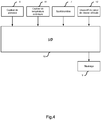
- the device comprises a calculation unit 10, a pressure sensor 6 in the intake manifold 4, an external temperature sensor 11, an accelerometer 7 measuring longitudinal acceleration values of the vehicle, a longitudinal speed measuring device 12 of the vehicle and a storage unit 9.
- the computing device 10 receives data from the other elements of the device and is able to implement the method of the invention described above.
- the storage unit 9 is able to store information from the other elements of the device.
Landscapes
- Engineering & Computer Science (AREA)
- Chemical & Material Sciences (AREA)
- Combustion & Propulsion (AREA)
- Mechanical Engineering (AREA)
- General Engineering & Computer Science (AREA)
- Combined Controls Of Internal Combustion Engines (AREA)
Applications Claiming Priority (1)
| Application Number | Priority Date | Filing Date | Title |
|---|---|---|---|
| FR1651725A FR3048453B1 (fr) | 2016-03-01 | 2016-03-01 | Procede et dispositif de calcul d'une quantite d'air dans un collecteur d'admission de moteur de vehicule et vehicule associe |
Publications (1)
| Publication Number | Publication Date |
|---|---|
| EP3214293A1 true EP3214293A1 (de) | 2017-09-06 |
Family
ID=55759842
Family Applications (1)
| Application Number | Title | Priority Date | Filing Date |
|---|---|---|---|
| EP17157675.4A Withdrawn EP3214293A1 (de) | 2016-03-01 | 2017-02-23 | Verfahren und vorrichtung zur berechnung einer luftmenge in einem fahrzeugmotor-ansaugrohr, und entsprechendes fahrzeug |
Country Status (2)
| Country | Link |
|---|---|
| EP (1) | EP3214293A1 (de) |
| FR (1) | FR3048453B1 (de) |
Cited By (1)
| Publication number | Priority date | Publication date | Assignee | Title |
|---|---|---|---|---|
| CN115163301A (zh) * | 2022-05-30 | 2022-10-11 | 东风柳州汽车有限公司 | 行车环境大气压力监测方法、装置、设备及存储介质 |
Citations (7)
| Publication number | Priority date | Publication date | Assignee | Title |
|---|---|---|---|---|
| EP0326065A2 (de) * | 1988-01-29 | 1989-08-02 | Hitachi, Ltd. | Steuerung für Motor-Kraftstoffeinspritzung |
| JPH03165265A (ja) * | 1989-11-24 | 1991-07-17 | Japan Aviation Electron Ind Ltd | 標高差計測装置 |
| US20040107946A1 (en) * | 2002-11-27 | 2004-06-10 | Toyota Jidosha Kabushiki Kaisha | Fuel injection amount control method and apparatus of internal combustion engine |
| US20060069491A1 (en) * | 2004-09-24 | 2006-03-30 | Toyota Jidosha Kabushiki Kaisha | Control device for internal combustion engine |
| US20060080033A1 (en) * | 2004-05-10 | 2006-04-13 | Michihisa Komatsu | Method and apparatus for map matching |
| EP1760474A2 (de) * | 2005-09-06 | 2007-03-07 | Sony Corporation | Geschwindigkeitserfassung, Positionserfassung und Navigationssystem |
| JP5499665B2 (ja) * | 2009-12-01 | 2014-05-21 | 株式会社アドヴィックス | 車両用制御装置 |
-
2016
- 2016-03-01 FR FR1651725A patent/FR3048453B1/fr active Active
-
2017
- 2017-02-23 EP EP17157675.4A patent/EP3214293A1/de not_active Withdrawn
Patent Citations (7)
| Publication number | Priority date | Publication date | Assignee | Title |
|---|---|---|---|---|
| EP0326065A2 (de) * | 1988-01-29 | 1989-08-02 | Hitachi, Ltd. | Steuerung für Motor-Kraftstoffeinspritzung |
| JPH03165265A (ja) * | 1989-11-24 | 1991-07-17 | Japan Aviation Electron Ind Ltd | 標高差計測装置 |
| US20040107946A1 (en) * | 2002-11-27 | 2004-06-10 | Toyota Jidosha Kabushiki Kaisha | Fuel injection amount control method and apparatus of internal combustion engine |
| US20060080033A1 (en) * | 2004-05-10 | 2006-04-13 | Michihisa Komatsu | Method and apparatus for map matching |
| US20060069491A1 (en) * | 2004-09-24 | 2006-03-30 | Toyota Jidosha Kabushiki Kaisha | Control device for internal combustion engine |
| EP1760474A2 (de) * | 2005-09-06 | 2007-03-07 | Sony Corporation | Geschwindigkeitserfassung, Positionserfassung und Navigationssystem |
| JP5499665B2 (ja) * | 2009-12-01 | 2014-05-21 | 株式会社アドヴィックス | 車両用制御装置 |
Cited By (2)
| Publication number | Priority date | Publication date | Assignee | Title |
|---|---|---|---|---|
| CN115163301A (zh) * | 2022-05-30 | 2022-10-11 | 东风柳州汽车有限公司 | 行车环境大气压力监测方法、装置、设备及存储介质 |
| CN115163301B (zh) * | 2022-05-30 | 2023-10-31 | 东风柳州汽车有限公司 | 行车环境大气压力监测方法、装置、设备及存储介质 |
Also Published As
| Publication number | Publication date |
|---|---|
| FR3048453A1 (fr) | 2017-09-08 |
| FR3048453B1 (fr) | 2020-12-18 |
Similar Documents
| Publication | Publication Date | Title |
|---|---|---|
| EP1644627B1 (de) | Verfahren zur echtzeitbestimmung einer kraftstoffeinspritzungsströmungscharakteristik | |
| EP2935828B1 (de) | Diagnoseverfahren für aufgeladenen motor und zugehöriger motor | |
| EP2162609B1 (de) | Verfahren zum starten eines verbrennungsmotors | |
| FR3065990A1 (fr) | Procede de reactualisation d’une dynamique d’adaptation d’une valeur de richesse a une consigne dans un moteur | |
| WO2017093638A1 (fr) | Procédé d'estimation de masse enfermée dans la chambre de combustion d'un cylindre d'un moteur à combustion interne de véhicule automobile | |
| EP2699778B1 (de) | Verfahren zur fehlerdiagnose eines aufgeladenen motors und aufgeladener motor | |
| EP0522908B1 (de) | Verfahren und System um die Luftmenge in einem Zylinder einer Brennkraftmaschine zuzurechnen | |
| FR2886345A1 (fr) | Methode d'estimation par un filtre non-lineaire adaptatif de la richesse dans un cylindre d'un moteur a combustion | |
| FR2549143A1 (fr) | Methode de controle de l'alimentation en carburant, pour moteurs a combustion interne en phase d'acceleration | |
| FR3048453A1 (fr) | Procede et dispositif de calcul d'une quantite d'air dans un collecteur d'admission de moteur de vehicule et vehicule associe | |
| FR2835281A1 (fr) | Procede d'estimation de la masse d'air admise dans une chambre de combustion d'un moteur, et vehicule de mise en oeuvre | |
| EP4166776B1 (de) | Verfahren zur diagnose der plausibilität eines luftdurchflussmessersensors in einer brennkraftmaschine | |
| EP2507491B1 (de) | System und verfahren zur schätzung der masse von in einem partikelfilter aufbewahrten partikeln eines kraftfahrzeugs | |
| EP3004608B1 (de) | Verfahren zur messung des schadstoffausstosses eines verbrennungsmotors und verfahren zur steuerung des motors | |
| EP0886055B1 (de) | Verfahren und Vorrichtung zur Steuerung des Betriebs einer fremdgezündeten Brennkraftmaschine | |
| EP0736680A1 (de) | Verfahren zur Selbstkorrektor von physikalischen Parametern für ein dynamisches System, wie zum Beispiel eine Brennkraftmaschine | |
| FR2945078A1 (fr) | Procede de controle du fonctionnement d'un moteur | |
| FR3090036A1 (fr) | Procede de correction d’une estimation des oxydes d’azote dans une ligne d’echappement | |
| FR3047461A1 (fr) | Methodes et systemes de relance du regime moteur pour sortir du mode de fonctionnement en roue libre | |
| EP2058492B1 (de) | Verfahren zum Kaltstart eines Verbrennungsmotors | |
| EP2751416A1 (de) | System und verfahren zur steuerung des verbrennungsmotors eines kraftfahrzeugs mit hochdruck- und niederdruck-abgasrückführungsschaltungen in einem übergangsmodusbetrieb | |
| FR2724432A1 (fr) | Procede et dispositif de suppression des oscillations longitudinales d'un vehicule automobile a moteur | |
| FR3075269A1 (fr) | Procede de detection d'un pre-allumage d'un melange d'air frais et de carburant | |
| FR3086335A1 (fr) | Procede de calcul d’une puissance de consigne d’une turbine dans un turbocompresseur | |
| FR2909762A1 (fr) | Systeme et procede de determination du bruit de combustion dans au moins un cylindre de moteur a combustion interne |
Legal Events
| Date | Code | Title | Description |
|---|---|---|---|
| PUAI | Public reference made under article 153(3) epc to a published international application that has entered the european phase |
Free format text: ORIGINAL CODE: 0009012 |
|
| STAA | Information on the status of an ep patent application or granted ep patent |
Free format text: STATUS: THE APPLICATION HAS BEEN PUBLISHED |
|
| AK | Designated contracting states |
Kind code of ref document: A1 Designated state(s): AL AT BE BG CH CY CZ DE DK EE ES FI FR GB GR HR HU IE IS IT LI LT LU LV MC MK MT NL NO PL PT RO RS SE SI SK SM TR |
|
| AX | Request for extension of the european patent |
Extension state: BA ME |
|
| STAA | Information on the status of an ep patent application or granted ep patent |
Free format text: STATUS: THE APPLICATION IS DEEMED TO BE WITHDRAWN |
|
| 18D | Application deemed to be withdrawn |
Effective date: 20180307 |