EP3214366A1 - Éclairage linéaire et son procédé de montage - Google Patents
Éclairage linéaire et son procédé de montage Download PDFInfo
- Publication number
- EP3214366A1 EP3214366A1 EP17158587.0A EP17158587A EP3214366A1 EP 3214366 A1 EP3214366 A1 EP 3214366A1 EP 17158587 A EP17158587 A EP 17158587A EP 3214366 A1 EP3214366 A1 EP 3214366A1
- Authority
- EP
- European Patent Office
- Prior art keywords
- support profile
- linear
- coupling adapter
- light
- boards
- Prior art date
- Legal status (The legal status is an assumption and is not a legal conclusion. Google has not performed a legal analysis and makes no representation as to the accuracy of the status listed.)
- Granted
Links
Images


Classifications
-
- F—MECHANICAL ENGINEERING; LIGHTING; HEATING; WEAPONS; BLASTING
- F21—LIGHTING
- F21V—FUNCTIONAL FEATURES OR DETAILS OF LIGHTING DEVICES OR SYSTEMS THEREOF; STRUCTURAL COMBINATIONS OF LIGHTING DEVICES WITH OTHER ARTICLES, NOT OTHERWISE PROVIDED FOR
- F21V21/00—Supporting, suspending, or attaching arrangements for lighting devices; Hand grips
- F21V21/005—Supporting, suspending, or attaching arrangements for lighting devices; Hand grips for several lighting devices in an end-to-end arrangement, i.e. light tracks
-
- F—MECHANICAL ENGINEERING; LIGHTING; HEATING; WEAPONS; BLASTING
- F21—LIGHTING
- F21S—NON-PORTABLE LIGHTING DEVICES; SYSTEMS THEREOF; VEHICLE LIGHTING DEVICES SPECIALLY ADAPTED FOR VEHICLE EXTERIORS
- F21S4/00—Lighting devices or systems using a string or strip of light sources
- F21S4/20—Lighting devices or systems using a string or strip of light sources with light sources held by or within elongate supports
- F21S4/28—Lighting devices or systems using a string or strip of light sources with light sources held by or within elongate supports rigid, e.g. LED bars
-
- F—MECHANICAL ENGINEERING; LIGHTING; HEATING; WEAPONS; BLASTING
- F21—LIGHTING
- F21V—FUNCTIONAL FEATURES OR DETAILS OF LIGHTING DEVICES OR SYSTEMS THEREOF; STRUCTURAL COMBINATIONS OF LIGHTING DEVICES WITH OTHER ARTICLES, NOT OTHERWISE PROVIDED FOR
- F21V23/00—Arrangement of electric circuit elements in or on lighting devices
- F21V23/06—Arrangement of electric circuit elements in or on lighting devices the elements being coupling devices, e.g. connectors
-
- F—MECHANICAL ENGINEERING; LIGHTING; HEATING; WEAPONS; BLASTING
- F21—LIGHTING
- F21V—FUNCTIONAL FEATURES OR DETAILS OF LIGHTING DEVICES OR SYSTEMS THEREOF; STRUCTURAL COMBINATIONS OF LIGHTING DEVICES WITH OTHER ARTICLES, NOT OTHERWISE PROVIDED FOR
- F21V17/00—Fastening of component parts of lighting devices, e.g. shades, globes, refractors, reflectors, filters, screens, grids or protective cages
- F21V17/06—Fastening of component parts of lighting devices, e.g. shades, globes, refractors, reflectors, filters, screens, grids or protective cages the fastening being onto or by the lampholder
-
- F—MECHANICAL ENGINEERING; LIGHTING; HEATING; WEAPONS; BLASTING
- F21—LIGHTING
- F21V—FUNCTIONAL FEATURES OR DETAILS OF LIGHTING DEVICES OR SYSTEMS THEREOF; STRUCTURAL COMBINATIONS OF LIGHTING DEVICES WITH OTHER ARTICLES, NOT OTHERWISE PROVIDED FOR
- F21V17/00—Fastening of component parts of lighting devices, e.g. shades, globes, refractors, reflectors, filters, screens, grids or protective cages
- F21V17/10—Fastening of component parts of lighting devices, e.g. shades, globes, refractors, reflectors, filters, screens, grids or protective cages characterised by specific fastening means or way of fastening
- F21V17/104—Fastening of component parts of lighting devices, e.g. shades, globes, refractors, reflectors, filters, screens, grids or protective cages characterised by specific fastening means or way of fastening using feather joints, e.g. tongues and grooves, with or without friction
-
- F—MECHANICAL ENGINEERING; LIGHTING; HEATING; WEAPONS; BLASTING
- F21—LIGHTING
- F21V—FUNCTIONAL FEATURES OR DETAILS OF LIGHTING DEVICES OR SYSTEMS THEREOF; STRUCTURAL COMBINATIONS OF LIGHTING DEVICES WITH OTHER ARTICLES, NOT OTHERWISE PROVIDED FOR
- F21V3/00—Globes; Bowls; Cover glasses
-
- F—MECHANICAL ENGINEERING; LIGHTING; HEATING; WEAPONS; BLASTING
- F21—LIGHTING
- F21Y—INDEXING SCHEME ASSOCIATED WITH SUBCLASSES F21K, F21L, F21S and F21V, RELATING TO THE FORM OR THE KIND OF THE LIGHT SOURCES OR OF THE COLOUR OF THE LIGHT EMITTED
- F21Y2105/00—Planar light sources
- F21Y2105/10—Planar light sources comprising a two-dimensional [2D] array of point-like light-generating elements
-
- F—MECHANICAL ENGINEERING; LIGHTING; HEATING; WEAPONS; BLASTING
- F21—LIGHTING
- F21Y—INDEXING SCHEME ASSOCIATED WITH SUBCLASSES F21K, F21L, F21S and F21V, RELATING TO THE FORM OR THE KIND OF THE LIGHT SOURCES OR OF THE COLOUR OF THE LIGHT EMITTED
- F21Y2115/00—Light-generating elements of semiconductor light sources
- F21Y2115/10—Light-emitting diodes [LED]
Definitions
- the invention relates to a linear luminaire with a support profile, an optic and a luminous means according to the preamble of independent claim 1.
- the luminous means comprises a plurality of circuit boards each having a front surface and a rear surface and a plurality of light-emitting diodes mounted on the front surface.
- the support profile and the optics each have corresponding mounting means, so that the optics can be mounted on the support profile.
- the optics at least partially cover the light-emitting diodes of the luminous means when the optics and the luminous means are mounted on the carrier profile.
- Such linear lights can be used to illuminate rooms, squares, work surfaces, stands and the like.
- linear lights For the illumination of indoor and outdoor spaces nowadays often longitudinal lights are used, which extend along a space or an object on which they are arranged. Such lights are commonly referred to as linear lights and can, for example, directly on walls, suspended or mounted on ceilings or attached to it or be installed in ceilings.
- Linear luminaires typically comprise a straight or even curved, generally elongated or longitudinal support profile or base profile or housing, which is fastened directly or indirectly to the object or the wall or the ceiling.
- linear lamps often have one Light bar, along which a longitudinal light-emitting means such as a fluorescent tube or a series of light-emitting diodes or a plurality of lighting means and associated operating devices are attached.
- a series of light-emitting diodes as light sources (LED bulbs) is typically generated without additional optics or lens a punk-shaped line on an illuminated surface. Therefore, such linear lights are equipped with optics that covers the one or more bulbs so that the light generated is scattered, or has preferred radiation characteristics.
- a light distribution curve can be set, which is adapted to an intended use of the linear lamp. For example, optics determine hue, scatter and / or direction of the emitted light. Also such optics are used to complete the linear lights.
- the optic itself carries the illuminant, so that optics and light bar are identical.
- LED bulbs typically boards are equipped with LEDs.
- the term "board” in this context may refer to a printed circuit board (PCB) that is an electronic component carrier.
- PCB printed circuit board
- circuit boards are used for mechanical fastening and electrical connection of electronic components.
- printed circuit boards or printed circuit boards consist of an electrically insulating material with conductive connections (printed conductors) adhered thereto.
- conductive connections printed conductors
- the tracks are usually etched from a thin layer of copper.
- the components are usually soldered to pads or pads. Larger components can also be attached to the board with cable ties, glue or screwed connections.
- the associated board is typically equipped with terminals. For example, it is known to equip the board at its longitudinal ends with lateral plugs, via which the board can be connected to a power supply.
- the support profile When mounting a linear light, the support profile is usually attached to a target position on the wall, the ceiling or the object, for example screwed. Frequently, it is desired that the linear luminaire stands out as little as possible from the ceiling or wall or from the object. To do this they are partially embedded in the ceilings, walls or objects themselves or in panels connected to them. In this context, it is desirable that linear luminaires have as low a height as possible so that they can be integrated as simply and completely as possible into the ceiling, walls and objects.
- a wiring connected to a power source is arranged as a power supply so that it is accessible when the support profile is attached.
- One or more luminescent light strip or optics are then mounted on the base profile mostly detachable.
- the associated circuit board is connected to the wiring, so that the light emitting diodes can be operated.
- a linear lamp has a support profile, an optic and a light source.
- the illuminant comprises a plurality of circuit boards each having a front surface and a back surface and a plurality of LEDs mounted on the front surface.
- the support profile and the optics each have corresponding mounting means which are formed so that the optic is preferably detachably mountable on the support profile.
- the optics at least partially cover the light-emitting diodes of the luminous means when the optics and the luminous means are mounted on the carrier profile.
- the linear lamp further comprises a coupling adapter and the plurality of circuit boards of the lamp are each equipped with current paths. About the current paths, the LEDs are supplied with power. In this case, the coupling adapter connects the current paths of two adjacent of the plurality of boards together when the lamp is mounted on the support profile.
- Circuit boards as used in bulbs for linear lights, may have any basic shape. Typically, they are longitudinal. Usually they have a rectangular base. By the circuit board is equipped with current paths, the power can be distributed to supply the LEDs on the board itself or passed to the light emitting diodes. The board must be connected to only one place with the power source, which can also be done via other boards or other bulbs. A complex supply of LEDs via direct or group-wise connected external power conductors can be avoided.
- the term "longitudinal" in connection with the board or the linear lamp may refer to a linear, quasi-linear or even curved shape.
- the linear expansion is in any case greater than the expansion in width.
- the circuit board can be made substantially straight in a cross section along a longitudinal direction.
- the plurality of light emitting diodes mounted on the front surface of the board, or the series of light emitting diodes, may comprise one or more parallel rows of light emitting diodes.
- the term "row” in this context may refer to the fact that the LEDs are arranged along a curved, wavy, jagged or in particular straight line.
- light-emitting diode can be understood synonymously for light-emitting diode or light-emitting diode (LED).
- the light-emitting diodes can be configured in a plan view, for example, round, elliptical, square or rectangular. They can be mounted on the board, which can also be equipped with a control electronics for operating the LEDs.
- the light source may be referred to as an LED light source.
- LED lamps have various advantageous properties such as high energy efficiency, long life and cost-effective production. They allow an efficient lighting adapted to the respective application.
- the LEDs may also have an adjacent primary lens.
- Such primary lenses or primary optics can be provided, for example, for glare-free illumination of the light generated by the light-emitting diodes. You can also bundle the light generated by the LEDs, for example, in the direction of the optics. In this way, it is possible to dispense with further elements for bundling the light, for example reflectors, or their construction can be simplified. In addition, they can protect the LEDs, for example, from touching.
- the optics can cover the light-emitting diodes, in particular in a radiation direction, so that luminous properties of the luminous means can be adapted and the light-emitting diodes can be protected. Ideally, it completely covers the light-emitting diodes in all their emission directions.
- the optics can be used to influence the radiation characteristics of the linear luminaire and to determine a light distribution curve (LVK) of the linear luminaire.
- the optics can close off the linear luminaire towards the outside and thus be an essential visible part of the linear luminaire in a built-in or assembled state of the linear luminaire.
- the optics are transparent or at least partially transparent.
- transparent in this context may refer to translucent or at least partially transparent to visible light.
- translucent may refer in particular to a damped or undamped permeability of the light generated by means of the luminous means.
- the optics can be arbitrarily shaped and composed of any number of parts.
- the optics is longitudinal and manufactured in one piece.
- it may be made of a plastic such as a polycarbonate (PC) or a polymethyl methacrylate (PMMA).
- PC polycarbonate
- PMMA polymethyl methacrylate
- such plastics enable a robust design of the optics in many possible geometries.
- they can be translucent in many ways, so that the desired radiation characteristic can be predefined flexibly and adapted to an intended use.
- optics can be made of such a material relatively simple and inexpensive and have other preferred for use properties such as elasticity or longevity.
- the optics may be a diffuser, wherein a light-shaping film may be applied to the diffuser.
- the film is attached to an inner or outer side of the diffuser.
- the film can be provided with an adhesive layer so that it can be glued to the diffuser.
- Such a light-shaping film makes it possible to equip a standardized diffuser with properties adapted to a specific application.
- the diffuser can be configured in an application-oriented manner for defining a light distribution curve (LVK) of the linear luminaire.
- the use of the light-shaping film also allows efficient cost-effective production of the diffuser.
- the light-shaping film can be equipped with a light-shaping structure.
- the structure may be a nano or microstructure. By such a structure, the light penetrating the diffuser can be efficiently and specifically shaped.
- the term "longitudinal" in connection with the optics can be understood analogously to its use in connection with the board or the linear lamp. In particular, it can refer to a linear, quasi-linear or even curved shape.
- the longitudinal extent of the optics is in any case greater than their extension in width.
- the optics can be designed substantially straight in a cross section along a longitudinal direction. In such an embodiment, the optics can describe a rectangular area in a plan view.
- connection in connection with the coupling adapter and the current paths may relate in particular to an electrical connection.
- electrical connection as described below in more detail with the same compound and a mechanical connection can be made.
- the coupling adapter of the linear lamp which is electrically connected to the current paths, allows a transfer of electricity from one board to another board.
- a separate connection of the individual boards is not necessary.
- it allows a coupling for powering the boards perpendicular to the surfaces of the board or perpendicular to the linear expansion of the linear lamp.
- a vertical coupling for powering the boards When mounted on a ceiling of the coupling adapter so for example, a vertical coupling for powering the boards.
- he can, as will be described in more detail below, serve as a vertical connector.
- the light source can thus be used, for example, from bottom to top in the linear light or its support profile and at the same time or in one step via the coupling adapter already connected to the power source.
- An additional connection of the boards via horizontal or other connectors or a separate wiring is not necessary. This allows an efficient insertion and removal of the bulb.
- For ceiling mounting of the entire linear lamp its support profile is preferably designed to fit.
- vertical connector in this context refers to linear luminaires, which are mounted on ceilings and aligned horizontally or have a horizontal longitudinal extent.
- the boards are inserted vertically or quasi vertically.
- the coupling adapter allows a horizontal coupling and can serve as a horizontal connector.
- the terms vertical and horizontal are therefore to be understood analogously offset in connection with the invention, depending on the application of the linear lamp. Since linear lamps of the inventive type are often aligned horizontally or mounted on ceilings, in the present description, for the sake of simplicity, the term vertical is used by way of example in connection with the coupling adapter. However, this is not to be construed as limiting the subject matter of the claimed invention.
- the coupling adapter and the current paths formed on the board also allow a relatively low height of the linear lamp. This can be achieved that the linear light is efficiently recessed completely in a ceiling.
- the overall height can be sufficiently low that the linear light is embedded in a concrete floor, without any need for adjustments with respect to reinforcement of the concrete floor.
- the lighting means and the coupling adapter between the support profile and the optics are arranged, wherein a distance between an outer side facing away from the light source of the support profile and a side facing away from the light source optics is at most about 20 mm, at most about 19 mm or at most about 18 mm and in particular between 10 mm and 20 mm.
- the mentioned distance can define a height of the linear lamp.
- This preferred embodiment of the linear lamp allows the realization of the linear lamp with a relatively low height.
- linear luminaires with heights in the above-mentioned dimension or size are suitable for installation in a ceiling or wall.
- the linear light can be sunk into the ceiling or wall, so that the optics is flush with the ceiling or wall.
- the support profile may be formed from a sheet of aluminum or steel. Such a support profile allows, inter alia, an installation in a ceiling made for example of concrete.
- the coupling adapter comprises a support profile part and two platinum parts, wherein the support profile part on the support profile and the two board parts are each mounted on one of the two adjacent of the plurality of boards, so that the two board parts are connected to the support profile part, when the lamp on the support profile is mounted.
- a coupling adapter allows a comfortable connection and simultaneous power supply of the boards. This can allow efficient assembly and disassembly of the boards.
- a first of the two board parts of the coupling adapter are fastened to the back of one of the two adjacent ones of the plurality of boards and a second of the two board parts of the coupling adapter to the back of the other of the two adjacent ones of the several boards.
- the boards can be efficiently coupled and mounted on their rear side or the LEDs facing away side.
- the support profile part of the coupling adapter preferably has a first insertion structure and the two platinum parts of the coupling adapter each have a corresponding second insertion structure, wherein the first insertion structure and the second insertion structures are inserted into one another when the illumination means is mounted on the support profile.
- first and second Einsteck Modellen allow easy, safe and efficient assembly and coupling of the boards in the plug / socket principle.
- the plug-in structures can in particular be designed such that they are inserted vertically or quasi vertically into one another.
- the support profile part of the coupling adapter comprises a first positioning structure, which keeps the two adjacent boards aligned with the support profile part of the coupling adapter when the lighting means is mounted on the support profile.
- the first positioning structure can be helpful in the assembly and disassembly of the boards, as it can ensure a precise alignment of the boards to the support section part.
- it can restrict or prevent in particular a longitudinal displacement of the boards or the optics relative to the supporting profile part of the coupling adapter. This can promote efficient and trouble-free operation.
- the two adjacent ones of the plurality of boards preferably each comprise a second positioning structure, which interact with the first positioning structure when the luminous means is mounted on the carrier profile.
- the second positioning structure enables an interaction adapted to the first positioning structure, so that an efficient positioning is made possible.
- Such posts and half-passages allow an efficient design of the positioning structure.
- the half-passages may be formed in particular at the edges of the two adjacent boards in the form of indentations on the edge.
- the plurality of circuit boards of the illuminant are each a multilayer board, wherein the current paths extend at least partially between two adjacent multiple layers of the multilayer board.
- multilayer board in this context refers to a printed circuit board consisting of more than one supporting plane. Usual number of levels is between two and twenty four. The individual levels can be connected to each other by means of plated-through holes. Such multilayer printed circuit boards enable the realization of relatively complex circuits and systems. Multilayer boards are also referred to as multilayer boards or multilayer boards (MLB).
- the current paths preferably comprise longitudinal paths and connections branching therefrom, wherein the longitudinal paths extend between the two adjacent ones of the multiple layers of the multilayer board and the connections connect the longitudinal paths with the light-emitting diodes.
- the connections may be formed as plated-through holes.
- the optic preferably carries the plurality of circuit boards of the luminous means.
- the optics carries the bulb and thus simultaneously assumes the function of a light bar, optics and lamps together form a unit. This allows an efficient and easy handling especially when inserting and removing the light source or when mounting and dismounting the boards or the light source on the support profile.
- the unit can be removed as a whole, for example, vertically from the linear lamp. Then the board with the defective LEDs can be separated from the optics and a new board can be connected to the optics. The new unit from the optics and the new board can then be used again vertically, for example, in the linear lamp.
- the at least one optical system can have a planar main surface which is closed laterally by, for example, right-angled side walls.
- it has lateral versions, in which at least one of the circuit boards of the luminous means can be inserted.
- the light source can be kept in a simple way, so that optics and lamps form a unit. Also allow such versions that the bulb is kept floating, so that different thermal length expansions of the board compared to the optics are possible.
- the supporting optics can thus form a unit together with one or more boards, which can be assembled and disassembled as a whole.
- the linear light preferably comprises a plurality of optics. It can therefore be provided in particular in the linear lamp several units of the aforementioned type. As a result, the linear light can be designed as a so-called endless linear lamp to a preferred length for the intended use.
- the support profile may have a virtually arbitrary length and the linear lamp may be equipped with a matching number of the aforementioned units and clutch adapters.
- the linear lamp comprises at least one further coupling adapter, which is identical in construction to the coupling adapter, wherein the at least one further coupling adapter connects the current paths of other two adjacent of the plurality of circuit boards, when the lighting means is mounted on the support profile.
- the term "at least one" in the context of certain components of the invention may refer to the fact that in a preferred embodiment in each case more of the components are present.
- the linear light can be equipped with a number of coupling adapters, which fits to a number of boards provided for a desired length of the linear light.
- the linear lamp comprises a ballast, which is connected to the coupling adapter, in particular electrically connected.
- the ballast is in particular directly and not connected via other components such as other boards to the coupling adapter. It can also be mounted on the same coupling adapter as for example screwed to it or the like. Alternatively, it can also be mounted directly to the board such as glued or soldered on it and at the same time connected directly to the coupling adapter.
- the at least one more Coupling adapter itself does not have to be connected to another ballast, but can transfer current from the current paths of a board on the current paths of the adjacent board. In this way, all boards of the bulb can be efficiently powered and controlled by a convenient number of ballasts with power. In particular, it can also be prevented that more ballasts are present than is necessary for stable operation.
- the support profile of the linear lamp is grounded. This allows easy and safe operation of the linear lamp.
- Another aspect of the invention relates to a method for mounting a linear lamp as described above on a ceiling.
- the method comprises the steps of: attaching a supporting profile of the linear lamp to the ceiling; Mounting a coupling adapter on the supporting profile; Connecting at least one circuit board of a luminous means of the linear luminaire with an optic of the linear luminaire to form a unit; Connecting the coupling adapter to a power supply; and mounting the unit to the support profile so that the coupling adapter is connected to current paths of the at least one circuit board.
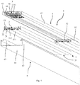
- Fig. 1 shows an embodiment of an inventive linear lamp 1 in perspective from below.
- the linear luminaire 1 comprises a longitudinal support profile 4, a luminous means which comprises a plurality of printed circuit boards 22 populated with light-emitting diodes 22, a plurality of longitudinal optics 5, a plurality of coupling adapters 3 and a longitudinal diffuser 6.
- the support profile 4 is provided for mounting directly on a ceiling. It has a longitudinal, in plan view rectangular base strip 41, which extends over the entire length of the linear lamp 1. On both sides of the base bar 41 then the support profile 4 each comprises a locking receptacle 43, each with an inner Einrastwand and an outer Einrastwand 42.
- the detent recesses 43 extend vertically downwards and extend over the entire length of the support section 4. At its end faces, the support section. 4 in each case two parallel cover receptacles 44.
- the optics 5 each comprise a corrugated in cross-section base plate 51 and laterally adjoining, extending at right angles upwardly side walls 52, which merge at its upper end in each case in a latching contour 53.
- the latching contours 53 have a horizontal base, from which two side walls each provided with a nose extend laterally upwards. They are designed so that they engage releasably in a mounting of the optics 5 on the support section 4 in the locking receptacles 43 and thus secure the optics 5 on the support section 4.
- the locking contours 53 and the locking receptacles 43 together form corresponding mounting means.
- the base plate 51 is configured with three longitudinal curvatures 511. The transitions of the bulges 511 to each other form two upwardly directed supports 512. Between the horizontal base of the locking contours 53 and the supports 512 of the base plate 51 more of the boards 2 are inserted, so that the boards 2 are supported or held by the optics 5.
- the boards 2 each have a front surface 21, which are equipped with six parallel rectilinear rows of LEDs 22.
- the optics 5 covers the light-emitting diodes 22 in their emission direction, with two rows of light-emitting diodes 22 each being associated with a bulge 511 of the base plate 51 of the optics 5.
- the coupling adapters 3 each comprise a support profile part 31 and two platinum parts 32.
- the support profile part 31 is mounted on the support profile 4.
- the board parts 32 are each attached to each other adjacent to two adjacent boards 2.
- the diffuser 6 is formed quasi U-shaped in cross section. It comprises a planar, rectangular in plan view main section 61, which merges at its longitudinal sides in each case in a right angle adjoining side wall 62.
- the two side walls 62 have against their upper ends in each case an outwardly directed latching portion 63. They are designed so that they engage releasably in a mounting of the diffuser on the support section 4 in the locking receptacles 43 and thus secure the diffuser 6 on the support section 4.
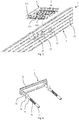
- the linear lamp 1 is shown in perspective from above. It can be seen that the boards 2 have a rear surface 26 opposite the front surface 21.
- Each of the optics 5 carries two boards 2, so that in each case one optic 5 and two boards 2 together form a unit.
- the rear sides 26 of the boards 2 are each equipped with one of the board parts 32 of the coupling adapter 3 against the longitudinal ends.
- One of the two boards 2 of the left unit, in Fig. 2 If this is the right board 2, it is also equipped on its rear side 26 with a ballast 8.
- Fig. 3 shows one of the boards 2 in an exploded perspective view.
- the bottom layer is a first copper layer 237 and forms the front surface 21 of the board 2.
- the first copper layer 237 comprises a solder mask and the six rows each having forty-one cuboid LEDs 22.
- Above the first copper layer 237 includes a first insulating layer 236 made of, for example, an FR4 material.
- FR4 materials are flame retardant and are made of composite materials consisting of epoxy resin and a glass fiber fabric.
- a second copper layer 235 adjoins.
- the second copper layer 235 serves to shield the first copper layer 237 from a third copper layer 233. As a result, afterglow of the light-emitting diodes can be prevented.
- a second insulating layer 234 is arranged, which may also be made of a FR4 material.
- the third copper layer 233 is equipped with seven, longitudinally extending, straight and parallel longitudinal tracks of current paths 24.
- a third insulating layer 232 adjoins the third copper layer 233.
- the third insulating layer 232 may in turn be made of a FR4 material.
- a fourth copper layer 231 is disposed on the third insulating layer 232.
- the fourth copper layer 231 is equipped with the board parts 32 of the coupling adapter 3.
- the LEDs 22 are each connected by means of a via as a connection of the current paths 24 with one of the longitudinal paths of the current paths 24.
- the board parts 32 of the coupling adapter 3 are connected by means of plated-through holes as terminals of the current paths 24 with the longitudinal paths of the current paths 24.
- each coupling adapter 3 In Fig. 4 and Fig. 5 two adjacent boards 2 are shown with an associated coupling adapter 3 in perspective from above and from below.
- the two board parts 32 of each coupling adapter 3 each have a foot portion 321, via which they are mounted on the back 26 of the associated board 2. Further, they include seven upwardly aligned in-line male plugs 322 as a second plug-in structure. Each of the seven plugs 322 is connected via a via to one of the longitudinal tracks of the current paths 24 (in Fig. 4 and Fig. 5 not visible) connected.
- each coupling adapter 3 comprises a base plate 311, from which extend two parallel rows each with seven female plug receptacles 312 as a first plug-in structure down.
- the plugs 322 of the board parts 32 and the plug receptacles 312 of the support profile part 31 are formed and positioned corresponding to one another.
- the plug 322 of the support profile part 31 are vertically inserted into the adjacent plug receptacles 312 of the boards 5 and connected to them mechanically and electrically. So they are plugged into each other when the lamp is mounted on the support section 4.
- current from the longitudinal paths of the current paths 24 of a circuit board 2 via the vias and the Clutch adapter 3 on the longitudinal paths of the current paths 24 of the adjacent board 2 pass.
- the carrying profile part 31 of the coupling adapter 3 further comprises a post 313 extending downwards or in the direction of the sinkers 2 as a first positioning structure.
- the blanks 2 have at their longitudinal ends in each case a half-passage 27 integrally formed as a dimple as a second positioning structure.
- two of the half-passages 27 of the adjacent longitudinal ends form a passage which is formed corresponding to the post 313.
- the post 313 extends each support profile part 31 through one of the passages of the boards 2.
- the support profile part 31 has further on its underside holding elements 314, which extend downwards or in the direction of the boards 2.
- the boards 2 are equipped with corresponding openings 25.
- the holding elements 314 engage in the openings 25.
- the boards 2 are held by a clamping of the holding elements 314 in the openings 25 on the support profile part 31.
- the longitudinal ends or end faces are preferably covered. This can on the one hand be prevented that the linear lights cause damage when a person comes into contact with the inside of the front.
- the linear lamps themselves can be protected from dirt, moisture or the like.
- One problem that can arise with conventional covers is that individual components expand to different extents with changing internal or external temperatures. This makes it difficult to keep the end faces of the linear lights closed in all operating conditions or to ensure that the front covers hold reliable but not damage or affect the other components of the linear lights at changing temperatures.
- linear lights can be used:
- Example 1 is a linear lamp with a longitudinal support profile, an optic, a light source and a longitudinal cover or end cover, in which the light source and the optics are mounted on the support profile, so that the optics at least partially covers the light source in a radiation direction, the longitudinal cover a Cover plate which covers the support profile, the optics and the illuminant on a longitudinal side or end face of the linear lamp, and comprises a spring element, wherein the spring element is arranged so that it biases the cover plate with respect to the support profile, so that the cover plate in the direction of Support profile is pressed.
- the cover plate can be connected in the longitudinal direction movable with the support profile, so that they can be moved in the longitudinal direction.
- the cover plate is displaced outwards or in the longitudinal direction.
- the spring element ensures that the cover plate always bears against the support profile and thus the linear light remains closed.
- Example 2 is the linear lamp of Example 1, wherein the longitudinal cover has a pin which is fixedly connected to the cover plate and slidably extending into a pin receptacle of the support profile.
- a plurality of pins are provided.
- Such a construction with pin and pin holder allows a stable and longitudinally movable connection between the cover plate and support profile.
- a plurality of preferably parallel pins can be arranged in corresponding pin receptacles of the support profile.
- Example 3 is the linear lamp of Example 1 or 2, wherein the longitudinal cover comprises a support profile connector which is fixedly connected to the support profile, wherein the spring element acts between support profile connector and cover plate.
- the cover plate can be moved so efficiently relative to the support profile connector and thus also to the support profile.
- Example 4 is the linear lamp of Example 2 and 3, wherein the longitudinal cover comprises a fixedly arranged on the pin stop sleeve and the spring element comprises a movably arranged on the pin coil spring, wherein the Pin is movable relative to the support profile connector and wherein the coil spring is biased between the stop sleeve and support profile connector.
- the longitudinal cover comprises a fixedly arranged on the pin stop sleeve and the spring element comprises a movably arranged on the pin coil spring, wherein the Pin is movable relative to the support profile connector and wherein the coil spring is biased between the stop sleeve and support profile connector.
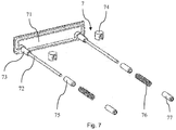
- Fig. 5 and Fig. 6 show an embodiment of a provided for the linear lamp 1 longitudinal cover 7 according to the above examples.
- the longitudinal cover 7 comprises a cover plate 71, which is shaped so that it can completely cover the end faces of the linear lamp 1. Perpendicular to the cover plate 71 extend two parallel pins 72 which are fixedly connected to the cover plate 71. Adjacent to the cover plate 71 are two spacer cylinders 73, to which the pins 72 connect.
- the cover plate 71, the spacer cylinder 73 and the pins 72 are integrally formed.
- a connecting sleeve 74 Adjacent to the two spacer cylinders 73, a connecting sleeve 74 is in each case arranged as a carrier profile connector on the pins 72.
- the connecting sleeves 74 each have a passage through which one of the pins 72 extends therethrough.
- the pins 72 are so axially movable relative to the connecting sleeves 74.
- Adjacent to the two connecting sleeves 74, a stop cylinder 75, a helical spring 76 as a spring element and a terminating sleeve 77 are respectively arranged in succession on the two pins 72.
- the pins 72 are axially movable relative to the stop cylinders 75 and the coil springs 76.
- the end sleeves 77 are fixedly connected to the pins 72.
- the coil springs are each clamped between one of the end sleeves 77 and one of the stopper cylinder 75.
- the pins 72, together with the spacer cylinders 73, the connecting sleeves 74, the stop cylinders 75, the coil springs 76 and the end sleeves 77 extend into each of the cover receptacles 44 of the support section 4.
- the connecting sleeves 74 are fixed to the Support profile 4 is connected and the pins 72 together with the end sleeves 77 axially movable in the cover receptacles 44.
- the coil springs 76 By compression and expansion of the coil springs 76, the pins 72 and the cover plate 71 can be moved toward and away from the support profile 4.
- the present disclosure also includes embodiments having any combination of features that are mentioned or shown above or below various embodiments. It also comprises individual features in the figures, even if they are shown there in connection with other features and / or are not mentioned above or below. Also, the alternatives of embodiments and individual alternatives described in the figures and the description may be excluded from the subject matter of the invention or from the disclosed subject matter.
- the disclosure includes embodiments which exclusively comprise the features described in the claims and in the exemplary embodiments as well as those which include additional other features.
Landscapes
- Engineering & Computer Science (AREA)
- General Engineering & Computer Science (AREA)
- Non-Portable Lighting Devices Or Systems Thereof (AREA)
- Fastening Of Light Sources Or Lamp Holders (AREA)
Applications Claiming Priority (1)
| Application Number | Priority Date | Filing Date | Title |
|---|---|---|---|
| CH00270/16A CH712189A1 (de) | 2016-03-02 | 2016-03-02 | Linearleuchte und Verfahren zur Montage einer solchen. |
Publications (2)
| Publication Number | Publication Date |
|---|---|
| EP3214366A1 true EP3214366A1 (fr) | 2017-09-06 |
| EP3214366B1 EP3214366B1 (fr) | 2019-06-12 |
Family
ID=55752122
Family Applications (1)
| Application Number | Title | Priority Date | Filing Date |
|---|---|---|---|
| EP17158587.0A Active EP3214366B1 (fr) | 2016-03-02 | 2017-03-01 | Éclairage linéaire et son procédé de montage |
Country Status (2)
| Country | Link |
|---|---|
| EP (1) | EP3214366B1 (fr) |
| CH (1) | CH712189A1 (fr) |
Families Citing this family (1)
| Publication number | Priority date | Publication date | Assignee | Title |
|---|---|---|---|---|
| US12474024B2 (en) * | 2021-08-06 | 2025-11-18 | Stepan Engineering Gmbh | LED illumination profile system and connecting technique |
Citations (4)
| Publication number | Priority date | Publication date | Assignee | Title |
|---|---|---|---|---|
| WO1999006759A1 (fr) * | 1997-07-28 | 1999-02-11 | Hewlett-Packard Company | Eclairage en bande |
| US20130252472A1 (en) * | 2012-03-26 | 2013-09-26 | Toshiba Lighting & Technology Corporation | Relay connector, module, module device, and luminaire |
| EP2685151A2 (fr) * | 2012-07-09 | 2014-01-15 | Panasonic Corporation | Dispositif d'illumination |
| US20140160747A1 (en) * | 2012-12-10 | 2014-06-12 | Samsung Electronics Co., Ltd. | Inter-connectable modular lighting fixtures |
-
2016
- 2016-03-02 CH CH00270/16A patent/CH712189A1/de not_active Application Discontinuation
-
2017
- 2017-03-01 EP EP17158587.0A patent/EP3214366B1/fr active Active
Patent Citations (4)
| Publication number | Priority date | Publication date | Assignee | Title |
|---|---|---|---|---|
| WO1999006759A1 (fr) * | 1997-07-28 | 1999-02-11 | Hewlett-Packard Company | Eclairage en bande |
| US20130252472A1 (en) * | 2012-03-26 | 2013-09-26 | Toshiba Lighting & Technology Corporation | Relay connector, module, module device, and luminaire |
| EP2685151A2 (fr) * | 2012-07-09 | 2014-01-15 | Panasonic Corporation | Dispositif d'illumination |
| US20140160747A1 (en) * | 2012-12-10 | 2014-06-12 | Samsung Electronics Co., Ltd. | Inter-connectable modular lighting fixtures |
Also Published As
| Publication number | Publication date |
|---|---|
| EP3214366B1 (fr) | 2019-06-12 |
| CH712189A1 (de) | 2017-09-15 |
Similar Documents
| Publication | Publication Date | Title |
|---|---|---|
| EP2151899B1 (fr) | Système de bande lumineuse | |
| EP2078895B1 (fr) | Système d'éclairage | |
| DE102005054422A1 (de) | Led-Lampe mit Leds auf einem Wärmeleitenden Ständer und Verfahren zur Herstellung der Led-Lampe | |
| DE202011051094U1 (de) | Leuchteneinheit für eine Leuchte, sowie Leuchte | |
| EP2270387B1 (fr) | Lampe plate à DEL | |
| CH709009B1 (de) | Befestigung einer Leiterplatte und einer Optik einer Leuchte. | |
| EP3187773B1 (fr) | Corps lumineux et lampadaire | |
| DE102009058310A1 (de) | LED-Leuchteneinsatz mit Lichtlenkelement | |
| EP2824380B1 (fr) | Éclairage | |
| DE202013010052U1 (de) | Anordnung zur Lichtabgabe sowie Leuchte mit einer solchen Anordnung | |
| EP3366991A1 (fr) | Support d'appareil pour luminaire | |
| EP3056805B2 (fr) | Optique allongée pour module à del | |
| EP3214366B1 (fr) | Éclairage linéaire et son procédé de montage | |
| WO2016096608A1 (fr) | Support à del muni d'une del et lampe munie d'un tel support à del | |
| DE202013100903U1 (de) | Durch eine beliebige Permutation kombinierbare Fahrzeuglampe | |
| EP3366981B1 (fr) | Gouttière d'éclairage destinée à former un boîtier d'éclairage | |
| EP3366986B1 (fr) | Capot du luminaire et luminaire | |
| EP2175188B1 (fr) | Eclairage | |
| CH715292B1 (de) | Optikrohling, Verfahren und Linearleuchte. | |
| DE102016104221A1 (de) | LED-Leuchte mit Lichtlenkelement | |
| EP4198385B1 (fr) | Positionnement et alignement d'une carte de circuit imprimé dans une lumière led | |
| EP3088796B1 (fr) | Rail profile destine au positionnement de modules a del dans des condensateurs lumineux | |
| DE102011102406A1 (de) | Leuchte mit LEDs | |
| EP2629004B1 (fr) | Lampe encastrée pour la zone extérieure, en particulier pour le montage dans un profilé de cadre de fenêtre | |
| DE202014010179U1 (de) | Ablängbare Einbauleuchte |
Legal Events
| Date | Code | Title | Description |
|---|---|---|---|
| PUAI | Public reference made under article 153(3) epc to a published international application that has entered the european phase |
Free format text: ORIGINAL CODE: 0009012 |
|
| STAA | Information on the status of an ep patent application or granted ep patent |
Free format text: STATUS: THE APPLICATION HAS BEEN PUBLISHED |
|
| AK | Designated contracting states |
Kind code of ref document: A1 Designated state(s): AL AT BE BG CH CY CZ DE DK EE ES FI FR GB GR HR HU IE IS IT LI LT LU LV MC MK MT NL NO PL PT RO RS SE SI SK SM TR |
|
| AX | Request for extension of the european patent |
Extension state: BA ME |
|
| STAA | Information on the status of an ep patent application or granted ep patent |
Free format text: STATUS: REQUEST FOR EXAMINATION WAS MADE |
|
| 17P | Request for examination filed |
Effective date: 20180305 |
|
| RBV | Designated contracting states (corrected) |
Designated state(s): AL AT BE BG CH CY CZ DE DK EE ES FI FR GB GR HR HU IE IS IT LI LT LU LV MC MK MT NL NO PL PT RO RS SE SI SK SM TR |
|
| STAA | Information on the status of an ep patent application or granted ep patent |
Free format text: STATUS: EXAMINATION IS IN PROGRESS |
|
| 17Q | First examination report despatched |
Effective date: 20180723 |
|
| GRAP | Despatch of communication of intention to grant a patent |
Free format text: ORIGINAL CODE: EPIDOSNIGR1 |
|
| STAA | Information on the status of an ep patent application or granted ep patent |
Free format text: STATUS: GRANT OF PATENT IS INTENDED |
|
| INTG | Intention to grant announced |
Effective date: 20190130 |
|
| GRAS | Grant fee paid |
Free format text: ORIGINAL CODE: EPIDOSNIGR3 |
|
| GRAA | (expected) grant |
Free format text: ORIGINAL CODE: 0009210 |
|
| STAA | Information on the status of an ep patent application or granted ep patent |
Free format text: STATUS: THE PATENT HAS BEEN GRANTED |
|
| AK | Designated contracting states |
Kind code of ref document: B1 Designated state(s): AL AT BE BG CH CY CZ DE DK EE ES FI FR GB GR HR HU IE IS IT LI LT LU LV MC MK MT NL NO PL PT RO RS SE SI SK SM TR |
|
| REG | Reference to a national code |
Ref country code: GB Ref legal event code: FG4D Free format text: NOT ENGLISH |
|
| REG | Reference to a national code |
Ref country code: CH Ref legal event code: EP |
|
| REG | Reference to a national code |
Ref country code: AT Ref legal event code: REF Ref document number: 1143028 Country of ref document: AT Kind code of ref document: T Effective date: 20190615 |
|
| REG | Reference to a national code |
Ref country code: DE Ref legal event code: R096 Ref document number: 502017001501 Country of ref document: DE |
|
| REG | Reference to a national code |
Ref country code: IE Ref legal event code: FG4D Free format text: LANGUAGE OF EP DOCUMENT: GERMAN |
|
| REG | Reference to a national code |
Ref country code: CH Ref legal event code: NV Representative=s name: LATSCHA SCHOELLHORN PARTNER AG, CH |
|
| REG | Reference to a national code |
Ref country code: NL Ref legal event code: MP Effective date: 20190612 |
|
| REG | Reference to a national code |
Ref country code: LT Ref legal event code: MG4D |
|
| PG25 | Lapsed in a contracting state [announced via postgrant information from national office to epo] |
Ref country code: LT Free format text: LAPSE BECAUSE OF FAILURE TO SUBMIT A TRANSLATION OF THE DESCRIPTION OR TO PAY THE FEE WITHIN THE PRESCRIBED TIME-LIMIT Effective date: 20190612 Ref country code: SE Free format text: LAPSE BECAUSE OF FAILURE TO SUBMIT A TRANSLATION OF THE DESCRIPTION OR TO PAY THE FEE WITHIN THE PRESCRIBED TIME-LIMIT Effective date: 20190612 Ref country code: HR Free format text: LAPSE BECAUSE OF FAILURE TO SUBMIT A TRANSLATION OF THE DESCRIPTION OR TO PAY THE FEE WITHIN THE PRESCRIBED TIME-LIMIT Effective date: 20190612 Ref country code: AL Free format text: LAPSE BECAUSE OF FAILURE TO SUBMIT A TRANSLATION OF THE DESCRIPTION OR TO PAY THE FEE WITHIN THE PRESCRIBED TIME-LIMIT Effective date: 20190612 Ref country code: NO Free format text: LAPSE BECAUSE OF FAILURE TO SUBMIT A TRANSLATION OF THE DESCRIPTION OR TO PAY THE FEE WITHIN THE PRESCRIBED TIME-LIMIT Effective date: 20190912 Ref country code: FI Free format text: LAPSE BECAUSE OF FAILURE TO SUBMIT A TRANSLATION OF THE DESCRIPTION OR TO PAY THE FEE WITHIN THE PRESCRIBED TIME-LIMIT Effective date: 20190612 |
|
| PG25 | Lapsed in a contracting state [announced via postgrant information from national office to epo] |
Ref country code: LV Free format text: LAPSE BECAUSE OF FAILURE TO SUBMIT A TRANSLATION OF THE DESCRIPTION OR TO PAY THE FEE WITHIN THE PRESCRIBED TIME-LIMIT Effective date: 20190612 Ref country code: GR Free format text: LAPSE BECAUSE OF FAILURE TO SUBMIT A TRANSLATION OF THE DESCRIPTION OR TO PAY THE FEE WITHIN THE PRESCRIBED TIME-LIMIT Effective date: 20190913 Ref country code: BG Free format text: LAPSE BECAUSE OF FAILURE TO SUBMIT A TRANSLATION OF THE DESCRIPTION OR TO PAY THE FEE WITHIN THE PRESCRIBED TIME-LIMIT Effective date: 20190912 Ref country code: RS Free format text: LAPSE BECAUSE OF FAILURE TO SUBMIT A TRANSLATION OF THE DESCRIPTION OR TO PAY THE FEE WITHIN THE PRESCRIBED TIME-LIMIT Effective date: 20190612 |
|
| PG25 | Lapsed in a contracting state [announced via postgrant information from national office to epo] |
Ref country code: CZ Free format text: LAPSE BECAUSE OF FAILURE TO SUBMIT A TRANSLATION OF THE DESCRIPTION OR TO PAY THE FEE WITHIN THE PRESCRIBED TIME-LIMIT Effective date: 20190612 Ref country code: RO Free format text: LAPSE BECAUSE OF FAILURE TO SUBMIT A TRANSLATION OF THE DESCRIPTION OR TO PAY THE FEE WITHIN THE PRESCRIBED TIME-LIMIT Effective date: 20190612 Ref country code: SK Free format text: LAPSE BECAUSE OF FAILURE TO SUBMIT A TRANSLATION OF THE DESCRIPTION OR TO PAY THE FEE WITHIN THE PRESCRIBED TIME-LIMIT Effective date: 20190612 Ref country code: PT Free format text: LAPSE BECAUSE OF FAILURE TO SUBMIT A TRANSLATION OF THE DESCRIPTION OR TO PAY THE FEE WITHIN THE PRESCRIBED TIME-LIMIT Effective date: 20191014 Ref country code: EE Free format text: LAPSE BECAUSE OF FAILURE TO SUBMIT A TRANSLATION OF THE DESCRIPTION OR TO PAY THE FEE WITHIN THE PRESCRIBED TIME-LIMIT Effective date: 20190612 Ref country code: NL Free format text: LAPSE BECAUSE OF FAILURE TO SUBMIT A TRANSLATION OF THE DESCRIPTION OR TO PAY THE FEE WITHIN THE PRESCRIBED TIME-LIMIT Effective date: 20190612 |
|
| PG25 | Lapsed in a contracting state [announced via postgrant information from national office to epo] |
Ref country code: IT Free format text: LAPSE BECAUSE OF FAILURE TO SUBMIT A TRANSLATION OF THE DESCRIPTION OR TO PAY THE FEE WITHIN THE PRESCRIBED TIME-LIMIT Effective date: 20190612 Ref country code: ES Free format text: LAPSE BECAUSE OF FAILURE TO SUBMIT A TRANSLATION OF THE DESCRIPTION OR TO PAY THE FEE WITHIN THE PRESCRIBED TIME-LIMIT Effective date: 20190612 Ref country code: IS Free format text: LAPSE BECAUSE OF FAILURE TO SUBMIT A TRANSLATION OF THE DESCRIPTION OR TO PAY THE FEE WITHIN THE PRESCRIBED TIME-LIMIT Effective date: 20191012 Ref country code: SM Free format text: LAPSE BECAUSE OF FAILURE TO SUBMIT A TRANSLATION OF THE DESCRIPTION OR TO PAY THE FEE WITHIN THE PRESCRIBED TIME-LIMIT Effective date: 20190612 |
|
| REG | Reference to a national code |
Ref country code: DE Ref legal event code: R097 Ref document number: 502017001501 Country of ref document: DE |
|
| PG25 | Lapsed in a contracting state [announced via postgrant information from national office to epo] |
Ref country code: TR Free format text: LAPSE BECAUSE OF FAILURE TO SUBMIT A TRANSLATION OF THE DESCRIPTION OR TO PAY THE FEE WITHIN THE PRESCRIBED TIME-LIMIT Effective date: 20190612 |
|
| PLBE | No opposition filed within time limit |
Free format text: ORIGINAL CODE: 0009261 |
|
| STAA | Information on the status of an ep patent application or granted ep patent |
Free format text: STATUS: NO OPPOSITION FILED WITHIN TIME LIMIT |
|
| PG25 | Lapsed in a contracting state [announced via postgrant information from national office to epo] |
Ref country code: PL Free format text: LAPSE BECAUSE OF FAILURE TO SUBMIT A TRANSLATION OF THE DESCRIPTION OR TO PAY THE FEE WITHIN THE PRESCRIBED TIME-LIMIT Effective date: 20190612 Ref country code: DK Free format text: LAPSE BECAUSE OF FAILURE TO SUBMIT A TRANSLATION OF THE DESCRIPTION OR TO PAY THE FEE WITHIN THE PRESCRIBED TIME-LIMIT Effective date: 20190612 |
|
| 26N | No opposition filed |
Effective date: 20200313 |
|
| PG25 | Lapsed in a contracting state [announced via postgrant information from national office to epo] |
Ref country code: SI Free format text: LAPSE BECAUSE OF FAILURE TO SUBMIT A TRANSLATION OF THE DESCRIPTION OR TO PAY THE FEE WITHIN THE PRESCRIBED TIME-LIMIT Effective date: 20190612 Ref country code: IS Free format text: LAPSE BECAUSE OF FAILURE TO SUBMIT A TRANSLATION OF THE DESCRIPTION OR TO PAY THE FEE WITHIN THE PRESCRIBED TIME-LIMIT Effective date: 20200224 |
|
| PG2D | Information on lapse in contracting state deleted |
Ref country code: IS |
|
| PG25 | Lapsed in a contracting state [announced via postgrant information from national office to epo] |
Ref country code: MC Free format text: LAPSE BECAUSE OF FAILURE TO SUBMIT A TRANSLATION OF THE DESCRIPTION OR TO PAY THE FEE WITHIN THE PRESCRIBED TIME-LIMIT Effective date: 20190612 |
|
| REG | Reference to a national code |
Ref country code: BE Ref legal event code: MM Effective date: 20200331 |
|
| PG25 | Lapsed in a contracting state [announced via postgrant information from national office to epo] |
Ref country code: LU Free format text: LAPSE BECAUSE OF NON-PAYMENT OF DUE FEES Effective date: 20200301 |
|
| PG25 | Lapsed in a contracting state [announced via postgrant information from national office to epo] |
Ref country code: IE Free format text: LAPSE BECAUSE OF NON-PAYMENT OF DUE FEES Effective date: 20200301 |
|
| PG25 | Lapsed in a contracting state [announced via postgrant information from national office to epo] |
Ref country code: BE Free format text: LAPSE BECAUSE OF NON-PAYMENT OF DUE FEES Effective date: 20200331 |
|
| GBPC | Gb: european patent ceased through non-payment of renewal fee |
Effective date: 20210301 |
|
| PG25 | Lapsed in a contracting state [announced via postgrant information from national office to epo] |
Ref country code: GB Free format text: LAPSE BECAUSE OF NON-PAYMENT OF DUE FEES Effective date: 20210301 |
|
| PG25 | Lapsed in a contracting state [announced via postgrant information from national office to epo] |
Ref country code: MT Free format text: LAPSE BECAUSE OF FAILURE TO SUBMIT A TRANSLATION OF THE DESCRIPTION OR TO PAY THE FEE WITHIN THE PRESCRIBED TIME-LIMIT Effective date: 20190612 Ref country code: CY Free format text: LAPSE BECAUSE OF FAILURE TO SUBMIT A TRANSLATION OF THE DESCRIPTION OR TO PAY THE FEE WITHIN THE PRESCRIBED TIME-LIMIT Effective date: 20190612 |
|
| PG25 | Lapsed in a contracting state [announced via postgrant information from national office to epo] |
Ref country code: MK Free format text: LAPSE BECAUSE OF FAILURE TO SUBMIT A TRANSLATION OF THE DESCRIPTION OR TO PAY THE FEE WITHIN THE PRESCRIBED TIME-LIMIT Effective date: 20190612 |
|
| P01 | Opt-out of the competence of the unified patent court (upc) registered |
Effective date: 20230529 |
|
| PGFP | Annual fee paid to national office [announced via postgrant information from national office to epo] |
Ref country code: DE Payment date: 20250319 Year of fee payment: 9 |
|
| PGFP | Annual fee paid to national office [announced via postgrant information from national office to epo] |
Ref country code: AT Payment date: 20250320 Year of fee payment: 9 |
|
| PGFP | Annual fee paid to national office [announced via postgrant information from national office to epo] |
Ref country code: FR Payment date: 20250325 Year of fee payment: 9 |
|
| PGFP | Annual fee paid to national office [announced via postgrant information from national office to epo] |
Ref country code: CH Payment date: 20250401 Year of fee payment: 9 |