EP3214416A1 - Débitmètre, en particulier pour utilisation soumise à obligation d'étalonnage - Google Patents
Débitmètre, en particulier pour utilisation soumise à obligation d'étalonnage Download PDFInfo
- Publication number
- EP3214416A1 EP3214416A1 EP16202379.0A EP16202379A EP3214416A1 EP 3214416 A1 EP3214416 A1 EP 3214416A1 EP 16202379 A EP16202379 A EP 16202379A EP 3214416 A1 EP3214416 A1 EP 3214416A1
- Authority
- EP
- European Patent Office
- Prior art keywords
- write
- write protection
- flowmeter
- evaluation device
- sensor elements
- Prior art date
- Legal status (The legal status is an assumption and is not a legal conclusion. Google has not performed a legal analysis and makes no representation as to the accuracy of the status listed.)
- Granted
Links
Images


Classifications
-
- G—PHYSICS
- G01—MEASURING; TESTING
- G01F—MEASURING VOLUME, VOLUME FLOW, MASS FLOW OR LIQUID LEVEL; METERING BY VOLUME
- G01F15/00—Details of, or accessories for, apparatus of groups G01F1/00 - G01F13/00 insofar as such details or appliances are not adapted to particular types of such apparatus
- G01F15/007—Details of, or accessories for, apparatus of groups G01F1/00 - G01F13/00 insofar as such details or appliances are not adapted to particular types of such apparatus comprising means to prevent fraud
-
- G—PHYSICS
- G06—COMPUTING OR CALCULATING; COUNTING
- G06F—ELECTRIC DIGITAL DATA PROCESSING
- G06F12/00—Accessing, addressing or allocating within memory systems or architectures
- G06F12/14—Protection against unauthorised use of memory or access to memory
- G06F12/1416—Protection against unauthorised use of memory or access to memory by checking the object accessibility, e.g. type of access defined by the memory independently of subject rights
- G06F12/1425—Protection against unauthorised use of memory or access to memory by checking the object accessibility, e.g. type of access defined by the memory independently of subject rights the protection being physical, e.g. cell, word, block
-
- G—PHYSICS
- G01—MEASURING; TESTING
- G01F—MEASURING VOLUME, VOLUME FLOW, MASS FLOW OR LIQUID LEVEL; METERING BY VOLUME
- G01F1/00—Measuring the volume flow or mass flow of fluid or fluent solid material wherein the fluid passes through a meter in a continuous flow
- G01F1/56—Measuring the volume flow or mass flow of fluid or fluent solid material wherein the fluid passes through a meter in a continuous flow by using electric or magnetic effects
- G01F1/58—Measuring the volume flow or mass flow of fluid or fluent solid material wherein the fluid passes through a meter in a continuous flow by using electric or magnetic effects by electromagnetic flowmeters
-
- G—PHYSICS
- G01—MEASURING; TESTING
- G01F—MEASURING VOLUME, VOLUME FLOW, MASS FLOW OR LIQUID LEVEL; METERING BY VOLUME
- G01F15/00—Details of, or accessories for, apparatus of groups G01F1/00 - G01F13/00 insofar as such details or appliances are not adapted to particular types of such apparatus
- G01F15/06—Indicating or recording devices
- G01F15/068—Indicating or recording devices with electrical means
-
- G—PHYSICS
- G06—COMPUTING OR CALCULATING; COUNTING
- G06F—ELECTRIC DIGITAL DATA PROCESSING
- G06F2212/00—Indexing scheme relating to accessing, addressing or allocation within memory systems or architectures
- G06F2212/10—Providing a specific technical effect
- G06F2212/1052—Security improvement
Definitions
- the invention relates to a flowmeter, in particular for custody transfer traffic, comprising a housing, at least one evaluation device arranged in the housing and having an interface arranged in the housing for communication with an external operator device, wherein the evaluation device can be written with data via the interface.
- Flowmeters of the aforementioned type are known from the prior art in many embodiments. Flow measurements in custody transfer are subject to specific requirements, for example, because of the need to ensure fairer trade or because measurement reliability is in the public interest, often by levying a quantitative tax on the transported and withdrawn medium.
- Verifiable flow measurements are subject to a variety of legal and institutional provisions, which ensure a special security of the measurements. Examples of this are provisions of the International Organization of Legal Metrology (Organization Internationale de Metrologie Legale (OIML)), here for example the directive OIML R 117 for measuring systems for liquids other than water. Recommendations of the OIML are often incorporated into national standards and thus receive wide-ranging attention.
- OIML Organization Internationale de Metrologie Legale
- a European directive dealing with the requirements for the approval of a custody transfer meter is the European Union Directive 2004/22 / EC.
- a key feature of flowmeters for custody transfer is their tamper resistance. It must be possible with great probability that a flowmeter for custody transfer traffic is manipulated externally in such a way that its measurement accuracy is no longer ensured or the measurement is falsified. This could be done, for example, by overwriting the calibration parameters determined for a flowmeter by a governmental inspection agency and stored in the flowmeter. Such a manipulation is in any case to prevent insofar as that manipulation is made more difficult by technical means and once a manipulation is clearly recognizable anyway.
- the object of the present invention is to provide a protection mechanism against influencing flow meters, which have a built-in interface, via which the evaluation of the flowmeter can be influenced, in which therefore something other than a purely mechanical access control is to be realized.
- the above-indicated and derived object is realized in the flowmeter initially described in that at least two write-protection sensor elements are arranged in the housing, that the housing outside has a receptacle for at least one write-protection influencing element that the write-protect influencing element in the inserted state in the Recording sets the write protection sensor elements in a write protection state that the write protection state of the write protection sensor elements is detected by the evaluation, wherein upon detection of the write protection state of at least one of the write protection sensor elements of the evaluation at least partially a description of the evaluation is prevented with data via the interface ,
- the arranged in the housing of the flowmeter interface is used to transfer data across the housing boundary of the flow meter, ie from an external, located outside the housing of the flowmeter control unit to the arranged inside the housing of the flowmeter evaluation or from the evaluation to the control unit.
- the interface can be realized by an electromechanical coupling, that is, a plug-socket construction, in the interface but it can also be a radio module, the electromagnetic information - in the visible or invisible area - the exchange of information between the evaluation of the Flow meter and an external control unit realized.
- the exchange of data takes place by means of a manufacturer-independent standardized communication protocol or via a manufacturer-dependent - ie proprietary - communication protocol.
- the interior of the flowmeter is not readily accessible. This means that, for example, calibration data obtained during a calibration process must be transported via the interface into the evaluation device of the flowmeter and stored there.
- the implementation according to the invention of protection against the abusive writing of the evaluation unit with data likewise works beyond the limits of the housing of the flowmeter.
- the influencing of the at least two write protection sensor elements by the write protection influencing element of whatever kind is detected by the evaluation device.
- the evaluation device is thus in any way - via a metrological interposition or directly - connected to the write protection sensor elements (or only with a write-protection sensor element), so that it can be evaluated by the influence state of the write protection sensor elements. It is not mandatory that the evaluation unit is physically connected to both write protection sensor elements, the state of influence of the two write protection sensor elements can also be revealed by recording only a single measurement signal.
- the use of at least two write-protect sensor elements allows a much higher level of security against interference from the outside than would be possible with a single influencing sensor element.
- the flowmeter is designed so that in the unused State of the write protection influencing element describing the evaluation unit via the interface with data is possible, whereas in the positioning of the write protection influencing element in the receptacle on or in the housing outside a writing of the evaluation is prevented with data via the interface.
- the state of influence of the write protection sensor elements is evaluated by the evaluation unit and a writing of the evaluation unit with data via the interface prevented in the case of detection of the write protection state.
- the flowmeter upon detection of the write protection state of at least one of the write protection sensor elements describing the evaluation is prevented at least with such data via the interface, which relate to the determination of the flow measurement, in particular a description of the evaluation is thus prevented in that the calibration data stored in the evaluation device are manipulated.
- At least one of the write protection sensor elements prevents writing of the evaluation device by completely deactivating the interface.
- no data can be exchanged via the interface.
- the interface could not be powered, or the corresponding software routine could be disabled, which implements data exchange over the interface.
- the flowmeter is provided that not the entire interface is disabled, but that the description of certain memory areas of the evaluation is disabled, in particular the memory areas in which the calibration data for the flowmeter are stored. In this variant, it would still be possible to exchange information with the flowmeter via the interface, but it would no longer be possible to influence the flowmeter in a significant manner for the measurement result.
- the recording is designed so that the write-protect influencing element is kept defined in the inserted state in the recording and the position of the write-protect influencing element secured by a seal.
- the seal may be, for example, a seal or a seal mark.
- the write-protection influencing element can be held, for example, by a cover which can be placed on the housing, the cover being held on the housing by means of the seal, so that the write-protection influencing element itself does not have to come into contact with the seal. It is important that the write-protect influencing element is removable only by breaking the seal from the holder and thus the read-only state of the flowmeter can be canceled.
- evaluation device If an evaluation device is mentioned here, then this does not mean that this evaluation device must be present in a single, contiguous electronic module; rather, it can also be distributed electronic components.
- the evaluation device will usually have at least one microcontroller or a microprocessor with the usual interfaces or peripheral components, so the evaluation device usually represents an embedded computer system.
- the write protection sensor elements are designed as magnetic field sensors and the write protection influencing element is configured as a magnet, in particular as a permanent magnet.
- the magnetic field sensors are arranged within the housing such that they are within the effective range of the write protection influencing element, that is the magnet, used in the holder.
- the Write protect sensor elements are configured as opposing first electrical baffle and second electrical baffle to form a write protection capacitor.
- the write-protection influencing element is designed as a third electrical guide surface, wherein this third guide surface in the inserted state in the receptacle facing the write-protection capacitor and forms with it a capacitive voltage divider.
- the third guide surface which realizes the write protection influencing element, in this case does not actively act on the at least two write protection sensors, but forms with the first and the second electrical guide surface of the write protection sensor elements a geometric-constructive capacitor arrangement, the has different physical behavior than unused third electrical guide surface in the receptacle of the housing. If the write protection capacitor is connected in accordance with the flowmeter, this physical change can be metrologically detected by the evaluation and evaluate just as clearly with respect to the presence or absence of the write protection influencing element.
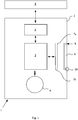
- Fig. 1 is shown in a very schematic manner, a flow meter 1, which is prepared for the custody transfer traffic.
- the flow meter 1 has a housing 2, in which an evaluation device 3 and an interface 4 for communication with an external operating device 5 are arranged. Also indicated is a measuring tube opening 6 through which a medium to be detected flows.
- the double arrow between the evaluation device 3 and the measuring tube opening 6 clarifies that the evaluation device - by whatever measuring principle - detects the flow through the measuring tube by measurement, which is the main task of the flowmeter 1.
- two write protection sensor elements 7a, 7b are arranged, with which a write protection functionality is realized.
- the housing outside of the housing 2 has a receptacle 8 for a write-protect influencing element 9.
- the flowmeter 1 is designed so that the write-protect influencing element 9 in the inserted state in the receptacle 8, the write-protection sensor elements 7a, 7b placed in a write protection state, the write protection state of the write-protect sensor elements 7a, 7b detected by the evaluation device 3, ie is detected, which is indicated by the double arrow.
- the evaluation device 3 is configured such that at least one of the write protection sensor elements 7a, 7b is at least partially prevented from writing the evaluation device 3 with data via the interface 4 upon detection of the write protection state.
- the illustrated flow meter 1 is encapsulated for reasons of explosion protection, so that therefore the housing 2 can not be opened without further notice.
- the interface 4 is designed such that nevertheless a data exchange with the external operating device 5 can be realized, in the present case it is an interface 4 based on a radio technology.
- the operating device 5 in this case is a handheld device that can be in contact with the flow meter 1, for example, in the installed state in the process.
- the interface 4 is a hardware interface based on a galvanic connection technology.
- the particular advantage of the illustrated flowmeter 1 is that the use of at least two write-protect sensor elements 7a, 7b means that a write-protection state can be realized in a tamper-proof manner with a very high level of security.
- the write protection state of at least one of the write protection sensor elements 7a, 7b is detected by the evaluation device 3. If only one of the write protection sensor elements 7a, 7b is in a write protection state, the writing of the evaluation device 3 with data via the interface 4, which relates to the determination of the flow measurement value, is prevented. In the present case, the writing of the evaluation device 3 with calibration data is prevented. This ensures that the flowmeter 1 is influenced in a significant manner for determining the flow measurement value when the write-protect influencing element 9 is inserted into the receptacle 8.
- Fig. 1 is indicated that the receptacle 8 is designed so that the write-protect influencing element 9 is kept defined in the inserted state in the receptacle 8 and the position of the write-protect influencing element 9 is secured by a seal 10.
- the seal 10 is a seal. Only after removal of the seal and thus after breaking the seal 10, the write-protect influencing element 9 is removable from the receptacle 8, so that the write-protection sensor elements 7a, 7b are no longer under the influence of the write-protect influencing element 9 and therefore no write protection state of Write-protection sensor elements 7a, 7b can be detected more. The seal break itself and thus the possible influence on the flow meter 1 is readily apparent.
- Fig. 2 is shown schematically how a special technical implementation of the write protection functionality of the flowmeter 1 described above can be realized.
- the write protection sensor elements 7a, 7b are designed as magnetic field sensors 11a, 11b and the write protection influencing element 9 is configured as a magnet 12, in the present case as a permanent magnet 12.
- the magnet 12 and the magnetic field sensors 11a, 11b are arranged collinear.
- the magnetic flux density field lines of the magnet 12 are substantially in the direction of the collinear arrangement of the magnet 12 and the magnetic field sensors 11a, 11b.
- the magnetic field lines are not shown, it is shown that the magnetic field sensors 11a, 11b and the magnet 12 lie on an axis A and the polarity of the permanent magnet 12 is also aligned in the direction of the axis course, polarity is indicated by the letters "S" and "N".
- the arrangement is clever because the magnetic field sensors 11a, 11b are so in the area of the largest field strength of the permanent magnet 12. It has proven to be clever to arrange the magnet 12 and the magnetic field sensors 11a, 11b as close as possible to one another.
- the representation in Fig. 2 is not to scale.
- a typical configuration could be such that with a wall thickness of 2 mm of the housing 2 a permanent magnet with a diameter of 10 mm and a height of about 5 mm is used in order to be able to excite a sufficient flux density.
- the magnetic field sensors 11a, 11b are designed as Hall-limit switches, in a specific embodiment, for example by the device with the designation AH1802 Diodes Incorporated.
- the magnetic field sensors 11a, 11b are mounted on the two sides of a circuit board 13 and soldered in a circuit not shown.
- the distance of the magnetic field sensors 11a, 11b with each other for example, be about one fifth of the average distance to the magnet 12.
- the first magnetic field sensor 11a is located about 6.5 mm away from the magnet 12, and the second magnetic field sensor 11b is located about 9 mm from the magnet 12, referring to the nearest boundary surface of the magnet 12 In the illustrated embodiment, therefore, the interface at which the south pole S is formed.
- the advantage of the arrangement is that it is practically impossible to compensate for the magnetic field of the magnet 12 by an external influence with another magnet so that both magnetic field sensors 11a, 11b designed as Hall limit switches simultaneously reach the uninfluenced state.
- both magnetic field sensors 11a, 11b designed as Hall limit switches simultaneously reach the uninfluenced state.
- more than two write-protect sensor elements can be used, but it has been shown that only by using two write-protect sensor elements over the use of a single write-protect sensor element, a significant gain in security is achieved, which is also sufficient for Requirements of devices in custody transfer traffic.
- the magnetic field sensors 11a, 11b designed as Hall limit switches have a typical limit value at which the limit value switch switches and, for example, switches from a high voltage level to a low level at the output or vice versa.
- the magnet 12 and the magnetic field sensors 11a, 11b designed as limit switches are preferably arranged and spaced from one another such that the magnet 12 generates a magnetic flux density in the receptacle 8 at the installation location of the magnetic field sensors 11a, 11b designed as limit switches, which is at least twice that strong is like the limit of the limit switch.
- the magnetic flux density generated at the mounting location of the magnetic field sensors 11a, 11b by the magnet 12 is about 8 times as high as the threshold at which the Hall limit switches 11a, 11b switch.
- This measure additionally makes it more difficult to influence the write protection arrangement from outside the flowmeter 1 such that both magnetic field sensors 11a, 11b simultaneously reach the unlocked state.
- the magnetic field sensors designed as limit value switches which trigger independently of the polarity of the magnetic field, a relatively small window of the magnetic flux density must be taken in order to unlock the limit value switches.
- the unlocked area is in the range of + - 2 mT
- the magnetic field generated by the permanent magnet 12 has a magnetic flux density of 20 mT at the mounting location of the first limit switch and has a magnetic flux density of 30 mT at the location of the second limit switch
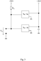
- FIG. 3 Finally, a simple circuit is shown, with an OR evaluation of in Fig. 2 shown Hall-limit switch - for example, realized by components of the type AH1802 from Diodes Incorporated - can be realized.
- the magnetic field sensors 11a, 11b are here Hall limit switch of the aforementioned type.
- the voltage supply of the components On the right side of the magnetic field sensors 11a, 11b, the voltage supply of the components is shown, on the left side, the electrical outputs of the magnetic field sensors 11a, 11b electrically interconnected and via a pull-up resistor R P to the operating voltage of 3.3 V. connected.
- the detection voltage Um for the state of influence of the magnetic field sensors 11a, 11b goes to ground as soon as the output of one of the magnetic field sensors 11a, 11b switches to ground. Therefore, the write protection state as a whole is detected by the indicated circuit, although only one magnetic field sensor 11a, 11b is in this state.
- the write protection sensor elements 7a, 7b are configured here as an opposing first electrical conduction surface 14a and second electrical conduction surface 14b, thus forming a write protection capacitor.
- the write protection influencing element 9 is in contrast to the above-described solution variant designed as a passive influencing element 9, namely as a third electrical guide surface 14c.
- the third guide surface 14c in the inserted state in the receptacle 8 faces the write protection capacitor consisting of the first electrical conduction surface 14a and the second electrical conduction surface 14b and forms with it a capacitive voltage divider.
- the first electrical conduction surface 14a, the second electrical conduction surface 14b, and the third electrical conduction surface 14c are aligned parallel to each other with the first electrical conduction surface 14a and the third electrical conduction surface 14c separated by the housing 2.
- the third electrical guide surface 14c should be grounded.
- the second guide surface 14b of the write protection capacitor is subjected to a periodic electrical voltage U P , here with a periodic electrical voltage having a non-zero arithmetic mean, namely a rectangular voltage with a duty cycle of 50%. Due to the capacitive coupling, the square-wave voltage also transfers to the first electrical guide surface 14a. In the inserted state of the third guide surface 14c to the housing wall 2 with respect to the first electrical guide surface 14a - in particular at grounding of the third conductive surface 14c -, the electrical voltage which can be tapped off from the first electrical conductive surface 14a is reduced due to the capacitive voltage divider forming.
- the voltage difference between the influenced state of the write protection capacitor by the third guide surface 14c and the unaffected state of the write protection capacitor due to a missing third guide surface 14c can be detected metrologically and makes the write protection state of the write protection sensor elements 7a, 7b in the form of write protection capacitor recognizable.
- the voltage at the first guide surface 14a of the write protection capacitor is tapped with high impedance by a measuring circuit 15 and supplied to the evaluation device 3 in a low-impedance manner, so that the evaluation device 3 can carry out a corresponding evaluation of the write protection state.
- the high-impedance tap of the detection voltage is realized by the first guide surface 14a via an isolating amplifier (buffer) realized with an operational amplifier.
- a peak detector is realized with a tens diode and a parallel and grounded RC element, so that the measuring voltage U m is in a DC voltage, whose height is evaluated.
- the resistor connected in parallel with the capacitor is used to discharge the capacitor, so that a peak value once detected is only held for a certain time.
Landscapes
- Physics & Mathematics (AREA)
- General Physics & Mathematics (AREA)
- Fluid Mechanics (AREA)
- Engineering & Computer Science (AREA)
- Theoretical Computer Science (AREA)
- Computer Security & Cryptography (AREA)
- General Engineering & Computer Science (AREA)
- Electromagnetism (AREA)
- Measuring Volume Flow (AREA)
- Storage Device Security (AREA)
- Arrangements For Transmission Of Measured Signals (AREA)
Applications Claiming Priority (1)
| Application Number | Priority Date | Filing Date | Title |
|---|---|---|---|
| DE102016104013.4A DE102016104013B3 (de) | 2016-03-04 | 2016-03-04 | Durchflussmessgerät, insbesondere für den eichpflichtigen Verkehr |
Publications (2)
| Publication Number | Publication Date |
|---|---|
| EP3214416A1 true EP3214416A1 (fr) | 2017-09-06 |
| EP3214416B1 EP3214416B1 (fr) | 2020-04-29 |
Family
ID=57485411
Family Applications (1)
| Application Number | Title | Priority Date | Filing Date |
|---|---|---|---|
| EP16202379.0A Active EP3214416B1 (fr) | 2016-03-04 | 2016-12-06 | Débitmètre, en particulier pour utilisation soumise à obligation d'étalonnage |
Country Status (6)
| Country | Link |
|---|---|
| US (1) | US10657072B2 (fr) |
| EP (1) | EP3214416B1 (fr) |
| JP (1) | JP6290480B2 (fr) |
| CN (1) | CN107152949B (fr) |
| DE (1) | DE102016104013B3 (fr) |
| RU (1) | RU2666184C2 (fr) |
Families Citing this family (3)
| Publication number | Priority date | Publication date | Assignee | Title |
|---|---|---|---|---|
| DE102018209826A1 (de) * | 2018-06-18 | 2019-12-19 | Siemens Aktiengesellschaft | Modulares Messsystem und Verfahren zum Erstellen eines Kompatibilitätsnachweises für ein solches Messsystem |
| EP3899448B1 (fr) | 2018-12-21 | 2024-03-27 | Endress + Hauser Flowtec AG | Débitmètre massique à effet coriolis muni d'un détecteur de champ magnétique |
| CN116047982B (zh) * | 2023-03-06 | 2023-07-04 | 武汉锐科光纤激光技术股份有限公司 | 分时光闸的控制系统 |
Citations (5)
| Publication number | Priority date | Publication date | Assignee | Title |
|---|---|---|---|---|
| EP0524839A2 (fr) * | 1991-07-25 | 1993-01-27 | Canon Kabushiki Kaisha | Méthode d'enregistrement et de reproduction magnétooptique d'information utilisant un glisseur flottant supportant une tête magnétique et appareil à cette fin |
| EP1195511A1 (fr) * | 1999-06-15 | 2002-04-10 | Hitachi, Ltd. | Dispositif de mesure de debit d'air faisant partie integrante d'un corps a etranglement a commande electronique |
| US20070171561A1 (en) * | 2006-01-24 | 2007-07-26 | Imation Corp. | Data storage cartridge with worm write-protection |
| DE102008002027A1 (de) * | 2008-05-28 | 2009-12-03 | Endress + Hauser Flowtec Ag | Messzelle, welche lösbar an einer dafür vorgesehenen Messvorrichtung anbringbar ist |
| WO2016022756A1 (fr) * | 2014-08-06 | 2016-02-11 | Magnetrol International, Incorporated | Sonde magnétostrictive amovible à étalonnage automatique |
Family Cites Families (6)
| Publication number | Priority date | Publication date | Assignee | Title |
|---|---|---|---|---|
| JP3762463B2 (ja) * | 1995-10-20 | 2006-04-05 | トキコテクノ株式会社 | 通信モード設定装置 |
| JPH11264332A (ja) * | 1997-12-17 | 1999-09-28 | Hitachi Ltd | 電制スロットルボディ一体型空気流量測定装置 |
| JP4660831B2 (ja) * | 2000-12-25 | 2011-03-30 | 東京瓦斯株式会社 | 流量計およびその電子的封印方法 |
| US8285506B2 (en) * | 2010-02-02 | 2012-10-09 | Gilbarco Inc. | Fuel dispenser pulser arrangement |
| IT1401649B1 (it) * | 2010-07-12 | 2013-08-02 | Snt Technologies S P A | Dispositivo di rilevamento della scrittura |
| CN204695350U (zh) * | 2015-06-05 | 2015-10-07 | 燕山大学里仁学院 | 一种学生信息管理用储存卡 |
-
2016
- 2016-03-04 DE DE102016104013.4A patent/DE102016104013B3/de not_active Withdrawn - After Issue
- 2016-12-06 EP EP16202379.0A patent/EP3214416B1/fr active Active
-
2017
- 2017-02-28 US US15/444,700 patent/US10657072B2/en active Active
- 2017-03-03 CN CN201710123142.0A patent/CN107152949B/zh active Active
- 2017-03-03 JP JP2017040570A patent/JP6290480B2/ja active Active
- 2017-03-03 RU RU2017107096A patent/RU2666184C2/ru active
Patent Citations (5)
| Publication number | Priority date | Publication date | Assignee | Title |
|---|---|---|---|---|
| EP0524839A2 (fr) * | 1991-07-25 | 1993-01-27 | Canon Kabushiki Kaisha | Méthode d'enregistrement et de reproduction magnétooptique d'information utilisant un glisseur flottant supportant une tête magnétique et appareil à cette fin |
| EP1195511A1 (fr) * | 1999-06-15 | 2002-04-10 | Hitachi, Ltd. | Dispositif de mesure de debit d'air faisant partie integrante d'un corps a etranglement a commande electronique |
| US20070171561A1 (en) * | 2006-01-24 | 2007-07-26 | Imation Corp. | Data storage cartridge with worm write-protection |
| DE102008002027A1 (de) * | 2008-05-28 | 2009-12-03 | Endress + Hauser Flowtec Ag | Messzelle, welche lösbar an einer dafür vorgesehenen Messvorrichtung anbringbar ist |
| WO2016022756A1 (fr) * | 2014-08-06 | 2016-02-11 | Magnetrol International, Incorporated | Sonde magnétostrictive amovible à étalonnage automatique |
Also Published As
| Publication number | Publication date |
|---|---|
| JP2017156350A (ja) | 2017-09-07 |
| DE102016104013B3 (de) | 2017-04-20 |
| RU2017107096A3 (fr) | 2018-09-03 |
| JP6290480B2 (ja) | 2018-03-07 |
| US20170255570A1 (en) | 2017-09-07 |
| EP3214416B1 (fr) | 2020-04-29 |
| CN107152949A (zh) | 2017-09-12 |
| RU2017107096A (ru) | 2018-09-03 |
| RU2666184C2 (ru) | 2018-09-10 |
| CN107152949B (zh) | 2021-06-08 |
| US10657072B2 (en) | 2020-05-19 |
Similar Documents
| Publication | Publication Date | Title |
|---|---|---|
| DE69401493T2 (de) | Vorrichtung zur kapazitiven echtheitsprüfung für einen in wertpapieren eingebetteten sicherheitsfaden | |
| EP3214416B1 (fr) | Débitmètre, en particulier pour utilisation soumise à obligation d'étalonnage | |
| DE102017101732A1 (de) | Kartenautomat mit Sicherheitsbenutzeroberfläche | |
| DE69526105T2 (de) | Ventil | |
| DE19908612B4 (de) | Anordnung zum Detektieren einer Rotation eines Drehelements | |
| DE10054470C2 (de) | Drehstellungsgeber zum Erfassen einer Drehstellung | |
| EP1855253B1 (fr) | Dispostif de montage comprenant un compteur d'énergie installé à un lieu de comptage | |
| EP1541795A2 (fr) | Récipient pour dépôts de valeur | |
| EP1785732B1 (fr) | Dispositif pour la détection de la rotation d'un élément rotatif | |
| DE102016107868B3 (de) | Vorrichtung zur Lageermittlung eines Magneten | |
| EP2987392B1 (fr) | Appareil électronique | |
| EP1108989A1 (fr) | Dispositif pour la mesure d'un débit d'un fluide de mesure dans un conduit de mesure | |
| DE102022102893B4 (de) | Sensoreinrichtung zur Erfassung wenigstens einer physikalischen Größe | |
| EP0382026B1 (fr) | Méthode et circuit de connexion d'un compteur électronique à un dispositif lecture-affichage | |
| DE19734989C2 (de) | System zur Überwachung von Geräten für die Erfassung und/oder Aufbereitung und/oder Übertragung von abrechnungsrelevanten elektrischen Verbrauchsgrößen sowie Gerät für ein solches System | |
| DE212009000026U1 (de) | Verbindungssensor zur Identifikation einer Anschlussstelle in einer Schalttafel | |
| EP0513952B1 (fr) | Circuit de détection de défaillance pour un ensemble électronique | |
| EP1890116B1 (fr) | Compteur de liquides infraudable | |
| DE212020000655U1 (de) | Sensorvorrichtung und Fluiddurchfluss-Messanordnung mit einer derartigen Sensorvorrichtung | |
| DE102011079355A1 (de) | Gehäuse | |
| EP2849158B1 (fr) | Ticket électronique avec protection anti-manipulation | |
| DE202007019437U1 (de) | Montageanordnung sowie Erfassungssystem mit einer solchen Anordnung | |
| DE102017130837A1 (de) | System, Messeinrichtung und Verfahren zur Erkennung eines Schließzustands | |
| DE202011108935U1 (de) | Vorrichtung zur Erkennung von Manipulationen an Verbrauchserfassungsgeräten | |
| DE102015113167A1 (de) | Sensoreinheit sowie Gebäudeüberwachungs- und/oder Steuerungssystem mit derartigen Sensoreinheiten |
Legal Events
| Date | Code | Title | Description |
|---|---|---|---|
| PUAI | Public reference made under article 153(3) epc to a published international application that has entered the european phase |
Free format text: ORIGINAL CODE: 0009012 |
|
| STAA | Information on the status of an ep patent application or granted ep patent |
Free format text: STATUS: THE APPLICATION HAS BEEN PUBLISHED |
|
| AK | Designated contracting states |
Kind code of ref document: A1 Designated state(s): AL AT BE BG CH CY CZ DE DK EE ES FI FR GB GR HR HU IE IS IT LI LT LU LV MC MK MT NL NO PL PT RO RS SE SI SK SM TR |
|
| AX | Request for extension of the european patent |
Extension state: BA ME |
|
| STAA | Information on the status of an ep patent application or granted ep patent |
Free format text: STATUS: REQUEST FOR EXAMINATION WAS MADE |
|
| 17P | Request for examination filed |
Effective date: 20180219 |
|
| RBV | Designated contracting states (corrected) |
Designated state(s): AL AT BE BG CH CY CZ DE DK EE ES FI FR GB GR HR HU IE IS IT LI LT LU LV MC MK MT NL NO PL PT RO RS SE SI SK SM TR |
|
| STAA | Information on the status of an ep patent application or granted ep patent |
Free format text: STATUS: EXAMINATION IS IN PROGRESS |
|
| 17Q | First examination report despatched |
Effective date: 20180904 |
|
| GRAP | Despatch of communication of intention to grant a patent |
Free format text: ORIGINAL CODE: EPIDOSNIGR1 |
|
| STAA | Information on the status of an ep patent application or granted ep patent |
Free format text: STATUS: GRANT OF PATENT IS INTENDED |
|
| INTG | Intention to grant announced |
Effective date: 20191204 |
|
| GRAS | Grant fee paid |
Free format text: ORIGINAL CODE: EPIDOSNIGR3 |
|
| GRAA | (expected) grant |
Free format text: ORIGINAL CODE: 0009210 |
|
| STAA | Information on the status of an ep patent application or granted ep patent |
Free format text: STATUS: THE PATENT HAS BEEN GRANTED |
|
| AK | Designated contracting states |
Kind code of ref document: B1 Designated state(s): AL AT BE BG CH CY CZ DE DK EE ES FI FR GB GR HR HU IE IS IT LI LT LU LV MC MK MT NL NO PL PT RO RS SE SI SK SM TR |
|
| REG | Reference to a national code |
Ref country code: GB Ref legal event code: FG4D Free format text: NOT ENGLISH |
|
| REG | Reference to a national code |
Ref country code: CH Ref legal event code: EP |
|
| REG | Reference to a national code |
Ref country code: AT Ref legal event code: REF Ref document number: 1264002 Country of ref document: AT Kind code of ref document: T Effective date: 20200515 |
|
| REG | Reference to a national code |
Ref country code: DE Ref legal event code: R096 Ref document number: 502016009740 Country of ref document: DE |
|
| REG | Reference to a national code |
Ref country code: IE Ref legal event code: FG4D Free format text: LANGUAGE OF EP DOCUMENT: GERMAN |
|
| REG | Reference to a national code |
Ref country code: NL Ref legal event code: FP |
|
| REG | Reference to a national code |
Ref country code: LT Ref legal event code: MG4D |
|
| PG25 | Lapsed in a contracting state [announced via postgrant information from national office to epo] |
Ref country code: NO Free format text: LAPSE BECAUSE OF FAILURE TO SUBMIT A TRANSLATION OF THE DESCRIPTION OR TO PAY THE FEE WITHIN THE PRESCRIBED TIME-LIMIT Effective date: 20200729 Ref country code: FI Free format text: LAPSE BECAUSE OF FAILURE TO SUBMIT A TRANSLATION OF THE DESCRIPTION OR TO PAY THE FEE WITHIN THE PRESCRIBED TIME-LIMIT Effective date: 20200429 Ref country code: PT Free format text: LAPSE BECAUSE OF FAILURE TO SUBMIT A TRANSLATION OF THE DESCRIPTION OR TO PAY THE FEE WITHIN THE PRESCRIBED TIME-LIMIT Effective date: 20200831 Ref country code: IS Free format text: LAPSE BECAUSE OF FAILURE TO SUBMIT A TRANSLATION OF THE DESCRIPTION OR TO PAY THE FEE WITHIN THE PRESCRIBED TIME-LIMIT Effective date: 20200829 Ref country code: GR Free format text: LAPSE BECAUSE OF FAILURE TO SUBMIT A TRANSLATION OF THE DESCRIPTION OR TO PAY THE FEE WITHIN THE PRESCRIBED TIME-LIMIT Effective date: 20200730 Ref country code: LT Free format text: LAPSE BECAUSE OF FAILURE TO SUBMIT A TRANSLATION OF THE DESCRIPTION OR TO PAY THE FEE WITHIN THE PRESCRIBED TIME-LIMIT Effective date: 20200429 Ref country code: SE Free format text: LAPSE BECAUSE OF FAILURE TO SUBMIT A TRANSLATION OF THE DESCRIPTION OR TO PAY THE FEE WITHIN THE PRESCRIBED TIME-LIMIT Effective date: 20200429 |
|
| PG25 | Lapsed in a contracting state [announced via postgrant information from national office to epo] |
Ref country code: HR Free format text: LAPSE BECAUSE OF FAILURE TO SUBMIT A TRANSLATION OF THE DESCRIPTION OR TO PAY THE FEE WITHIN THE PRESCRIBED TIME-LIMIT Effective date: 20200429 Ref country code: BG Free format text: LAPSE BECAUSE OF FAILURE TO SUBMIT A TRANSLATION OF THE DESCRIPTION OR TO PAY THE FEE WITHIN THE PRESCRIBED TIME-LIMIT Effective date: 20200729 Ref country code: RS Free format text: LAPSE BECAUSE OF FAILURE TO SUBMIT A TRANSLATION OF THE DESCRIPTION OR TO PAY THE FEE WITHIN THE PRESCRIBED TIME-LIMIT Effective date: 20200429 Ref country code: LV Free format text: LAPSE BECAUSE OF FAILURE TO SUBMIT A TRANSLATION OF THE DESCRIPTION OR TO PAY THE FEE WITHIN THE PRESCRIBED TIME-LIMIT Effective date: 20200429 |
|
| PG25 | Lapsed in a contracting state [announced via postgrant information from national office to epo] |
Ref country code: AL Free format text: LAPSE BECAUSE OF FAILURE TO SUBMIT A TRANSLATION OF THE DESCRIPTION OR TO PAY THE FEE WITHIN THE PRESCRIBED TIME-LIMIT Effective date: 20200429 |
|
| PG25 | Lapsed in a contracting state [announced via postgrant information from national office to epo] |
Ref country code: ES Free format text: LAPSE BECAUSE OF FAILURE TO SUBMIT A TRANSLATION OF THE DESCRIPTION OR TO PAY THE FEE WITHIN THE PRESCRIBED TIME-LIMIT Effective date: 20200429 Ref country code: DK Free format text: LAPSE BECAUSE OF FAILURE TO SUBMIT A TRANSLATION OF THE DESCRIPTION OR TO PAY THE FEE WITHIN THE PRESCRIBED TIME-LIMIT Effective date: 20200429 Ref country code: EE Free format text: LAPSE BECAUSE OF FAILURE TO SUBMIT A TRANSLATION OF THE DESCRIPTION OR TO PAY THE FEE WITHIN THE PRESCRIBED TIME-LIMIT Effective date: 20200429 Ref country code: SM Free format text: LAPSE BECAUSE OF FAILURE TO SUBMIT A TRANSLATION OF THE DESCRIPTION OR TO PAY THE FEE WITHIN THE PRESCRIBED TIME-LIMIT Effective date: 20200429 Ref country code: RO Free format text: LAPSE BECAUSE OF FAILURE TO SUBMIT A TRANSLATION OF THE DESCRIPTION OR TO PAY THE FEE WITHIN THE PRESCRIBED TIME-LIMIT Effective date: 20200429 Ref country code: IT Free format text: LAPSE BECAUSE OF FAILURE TO SUBMIT A TRANSLATION OF THE DESCRIPTION OR TO PAY THE FEE WITHIN THE PRESCRIBED TIME-LIMIT Effective date: 20200429 Ref country code: CZ Free format text: LAPSE BECAUSE OF FAILURE TO SUBMIT A TRANSLATION OF THE DESCRIPTION OR TO PAY THE FEE WITHIN THE PRESCRIBED TIME-LIMIT Effective date: 20200429 |
|
| REG | Reference to a national code |
Ref country code: DE Ref legal event code: R097 Ref document number: 502016009740 Country of ref document: DE |
|
| PG25 | Lapsed in a contracting state [announced via postgrant information from national office to epo] |
Ref country code: PL Free format text: LAPSE BECAUSE OF FAILURE TO SUBMIT A TRANSLATION OF THE DESCRIPTION OR TO PAY THE FEE WITHIN THE PRESCRIBED TIME-LIMIT Effective date: 20200429 Ref country code: SK Free format text: LAPSE BECAUSE OF FAILURE TO SUBMIT A TRANSLATION OF THE DESCRIPTION OR TO PAY THE FEE WITHIN THE PRESCRIBED TIME-LIMIT Effective date: 20200429 |
|
| PLBE | No opposition filed within time limit |
Free format text: ORIGINAL CODE: 0009261 |
|
| STAA | Information on the status of an ep patent application or granted ep patent |
Free format text: STATUS: NO OPPOSITION FILED WITHIN TIME LIMIT |
|
| 26N | No opposition filed |
Effective date: 20210201 |
|
| PG25 | Lapsed in a contracting state [announced via postgrant information from national office to epo] |
Ref country code: SI Free format text: LAPSE BECAUSE OF FAILURE TO SUBMIT A TRANSLATION OF THE DESCRIPTION OR TO PAY THE FEE WITHIN THE PRESCRIBED TIME-LIMIT Effective date: 20200429 |
|
| PG25 | Lapsed in a contracting state [announced via postgrant information from national office to epo] |
Ref country code: MC Free format text: LAPSE BECAUSE OF FAILURE TO SUBMIT A TRANSLATION OF THE DESCRIPTION OR TO PAY THE FEE WITHIN THE PRESCRIBED TIME-LIMIT Effective date: 20200429 |
|
| REG | Reference to a national code |
Ref country code: BE Ref legal event code: MM Effective date: 20201231 |
|
| PG25 | Lapsed in a contracting state [announced via postgrant information from national office to epo] |
Ref country code: LU Free format text: LAPSE BECAUSE OF NON-PAYMENT OF DUE FEES Effective date: 20201206 Ref country code: IE Free format text: LAPSE BECAUSE OF NON-PAYMENT OF DUE FEES Effective date: 20201206 |
|
| PG25 | Lapsed in a contracting state [announced via postgrant information from national office to epo] |
Ref country code: TR Free format text: LAPSE BECAUSE OF FAILURE TO SUBMIT A TRANSLATION OF THE DESCRIPTION OR TO PAY THE FEE WITHIN THE PRESCRIBED TIME-LIMIT Effective date: 20200429 Ref country code: MT Free format text: LAPSE BECAUSE OF FAILURE TO SUBMIT A TRANSLATION OF THE DESCRIPTION OR TO PAY THE FEE WITHIN THE PRESCRIBED TIME-LIMIT Effective date: 20200429 Ref country code: CY Free format text: LAPSE BECAUSE OF FAILURE TO SUBMIT A TRANSLATION OF THE DESCRIPTION OR TO PAY THE FEE WITHIN THE PRESCRIBED TIME-LIMIT Effective date: 20200429 |
|
| PG25 | Lapsed in a contracting state [announced via postgrant information from national office to epo] |
Ref country code: MK Free format text: LAPSE BECAUSE OF FAILURE TO SUBMIT A TRANSLATION OF THE DESCRIPTION OR TO PAY THE FEE WITHIN THE PRESCRIBED TIME-LIMIT Effective date: 20200429 |
|
| PG25 | Lapsed in a contracting state [announced via postgrant information from national office to epo] |
Ref country code: BE Free format text: LAPSE BECAUSE OF NON-PAYMENT OF DUE FEES Effective date: 20201231 |
|
| REG | Reference to a national code |
Ref country code: AT Ref legal event code: MM01 Ref document number: 1264002 Country of ref document: AT Kind code of ref document: T Effective date: 20211206 |
|
| PG25 | Lapsed in a contracting state [announced via postgrant information from national office to epo] |
Ref country code: AT Free format text: LAPSE BECAUSE OF NON-PAYMENT OF DUE FEES Effective date: 20211206 |
|
| P01 | Opt-out of the competence of the unified patent court (upc) registered |
Effective date: 20230607 |
|
| PGFP | Annual fee paid to national office [announced via postgrant information from national office to epo] |
Ref country code: CH Payment date: 20250101 Year of fee payment: 9 |
|
| REG | Reference to a national code |
Ref country code: CH Ref legal event code: U11 Free format text: ST27 STATUS EVENT CODE: U-0-0-U10-U11 (AS PROVIDED BY THE NATIONAL OFFICE) Effective date: 20260101 |
|
| PGFP | Annual fee paid to national office [announced via postgrant information from national office to epo] |
Ref country code: GB Payment date: 20251219 Year of fee payment: 10 |
|
| PGFP | Annual fee paid to national office [announced via postgrant information from national office to epo] |
Ref country code: FR Payment date: 20251223 Year of fee payment: 10 Ref country code: NL Payment date: 20251219 Year of fee payment: 10 |
|
| PGFP | Annual fee paid to national office [announced via postgrant information from national office to epo] |
Ref country code: DE Payment date: 20260217 Year of fee payment: 10 |