EP1890116B1 - Compteur de liquides infraudable - Google Patents
Compteur de liquides infraudable Download PDFInfo
- Publication number
- EP1890116B1 EP1890116B1 EP06016980A EP06016980A EP1890116B1 EP 1890116 B1 EP1890116 B1 EP 1890116B1 EP 06016980 A EP06016980 A EP 06016980A EP 06016980 A EP06016980 A EP 06016980A EP 1890116 B1 EP1890116 B1 EP 1890116B1
- Authority
- EP
- European Patent Office
- Prior art keywords
- electronic
- magneto
- counter unit
- sensor
- scanning sensor
- Prior art date
- Legal status (The legal status is an assumption and is not a legal conclusion. Google has not performed a legal analysis and makes no representation as to the accuracy of the status listed.)
- Active
Links
Images


Classifications
-
- G—PHYSICS
- G01—MEASURING; TESTING
- G01F—MEASURING VOLUME, VOLUME FLOW, MASS FLOW OR LIQUID LEVEL; METERING BY VOLUME
- G01F15/00—Details of, or accessories for, apparatus of groups G01F1/00 - G01F13/00 insofar as such details or appliances are not adapted to particular types of such apparatus
- G01F15/007—Details of, or accessories for, apparatus of groups G01F1/00 - G01F13/00 insofar as such details or appliances are not adapted to particular types of such apparatus comprising means to prevent fraud
-
- G—PHYSICS
- G01—MEASURING; TESTING
- G01F—MEASURING VOLUME, VOLUME FLOW, MASS FLOW OR LIQUID LEVEL; METERING BY VOLUME
- G01F1/00—Measuring the volume flow or mass flow of fluid or fluent solid material wherein the fluid passes through a meter in a continuous flow
- G01F1/05—Measuring the volume flow or mass flow of fluid or fluent solid material wherein the fluid passes through a meter in a continuous flow by using mechanical effects
- G01F1/06—Measuring the volume flow or mass flow of fluid or fluent solid material wherein the fluid passes through a meter in a continuous flow by using mechanical effects using rotating vanes with tangential admission
- G01F1/065—Measuring the volume flow or mass flow of fluid or fluent solid material wherein the fluid passes through a meter in a continuous flow by using mechanical effects using rotating vanes with tangential admission with radiation as transfer means to the indicating device, e.g. light transmission
-
- G—PHYSICS
- G01—MEASURING; TESTING
- G01F—MEASURING VOLUME, VOLUME FLOW, MASS FLOW OR LIQUID LEVEL; METERING BY VOLUME
- G01F1/00—Measuring the volume flow or mass flow of fluid or fluent solid material wherein the fluid passes through a meter in a continuous flow
- G01F1/05—Measuring the volume flow or mass flow of fluid or fluent solid material wherein the fluid passes through a meter in a continuous flow by using mechanical effects
- G01F1/06—Measuring the volume flow or mass flow of fluid or fluent solid material wherein the fluid passes through a meter in a continuous flow by using mechanical effects using rotating vanes with tangential admission
- G01F1/075—Measuring the volume flow or mass flow of fluid or fluent solid material wherein the fluid passes through a meter in a continuous flow by using mechanical effects using rotating vanes with tangential admission with magnetic or electromagnetic coupling to the indicating device
-
- G—PHYSICS
- G01—MEASURING; TESTING
- G01F—MEASURING VOLUME, VOLUME FLOW, MASS FLOW OR LIQUID LEVEL; METERING BY VOLUME
- G01F1/00—Measuring the volume flow or mass flow of fluid or fluent solid material wherein the fluid passes through a meter in a continuous flow
- G01F1/05—Measuring the volume flow or mass flow of fluid or fluent solid material wherein the fluid passes through a meter in a continuous flow by using mechanical effects
- G01F1/06—Measuring the volume flow or mass flow of fluid or fluent solid material wherein the fluid passes through a meter in a continuous flow by using mechanical effects using rotating vanes with tangential admission
- G01F1/075—Measuring the volume flow or mass flow of fluid or fluent solid material wherein the fluid passes through a meter in a continuous flow by using mechanical effects using rotating vanes with tangential admission with magnetic or electromagnetic coupling to the indicating device
- G01F1/0755—Measuring the volume flow or mass flow of fluid or fluent solid material wherein the fluid passes through a meter in a continuous flow by using mechanical effects using rotating vanes with tangential admission with magnetic or electromagnetic coupling to the indicating device with magnetic coupling only in a mechanical transmission path
-
- G—PHYSICS
- G01—MEASURING; TESTING
- G01F—MEASURING VOLUME, VOLUME FLOW, MASS FLOW OR LIQUID LEVEL; METERING BY VOLUME
- G01F1/00—Measuring the volume flow or mass flow of fluid or fluent solid material wherein the fluid passes through a meter in a continuous flow
- G01F1/05—Measuring the volume flow or mass flow of fluid or fluent solid material wherein the fluid passes through a meter in a continuous flow by using mechanical effects
- G01F1/10—Measuring the volume flow or mass flow of fluid or fluent solid material wherein the fluid passes through a meter in a continuous flow by using mechanical effects using rotating vanes with axial admission
- G01F1/103—Measuring the volume flow or mass flow of fluid or fluent solid material wherein the fluid passes through a meter in a continuous flow by using mechanical effects using rotating vanes with axial admission with radiation as transfer means to the indicating device, e.g. light transmission
-
- G—PHYSICS
- G01—MEASURING; TESTING
- G01F—MEASURING VOLUME, VOLUME FLOW, MASS FLOW OR LIQUID LEVEL; METERING BY VOLUME
- G01F1/00—Measuring the volume flow or mass flow of fluid or fluent solid material wherein the fluid passes through a meter in a continuous flow
- G01F1/05—Measuring the volume flow or mass flow of fluid or fluent solid material wherein the fluid passes through a meter in a continuous flow by using mechanical effects
- G01F1/10—Measuring the volume flow or mass flow of fluid or fluent solid material wherein the fluid passes through a meter in a continuous flow by using mechanical effects using rotating vanes with axial admission
- G01F1/115—Measuring the volume flow or mass flow of fluid or fluent solid material wherein the fluid passes through a meter in a continuous flow by using mechanical effects using rotating vanes with axial admission with magnetic or electromagnetic coupling to the indicating device
-
- G—PHYSICS
- G01—MEASURING; TESTING
- G01F—MEASURING VOLUME, VOLUME FLOW, MASS FLOW OR LIQUID LEVEL; METERING BY VOLUME
- G01F1/00—Measuring the volume flow or mass flow of fluid or fluent solid material wherein the fluid passes through a meter in a continuous flow
- G01F1/05—Measuring the volume flow or mass flow of fluid or fluent solid material wherein the fluid passes through a meter in a continuous flow by using mechanical effects
- G01F1/10—Measuring the volume flow or mass flow of fluid or fluent solid material wherein the fluid passes through a meter in a continuous flow by using mechanical effects using rotating vanes with axial admission
- G01F1/115—Measuring the volume flow or mass flow of fluid or fluent solid material wherein the fluid passes through a meter in a continuous flow by using mechanical effects using rotating vanes with axial admission with magnetic or electromagnetic coupling to the indicating device
- G01F1/1155—Measuring the volume flow or mass flow of fluid or fluent solid material wherein the fluid passes through a meter in a continuous flow by using mechanical effects using rotating vanes with axial admission with magnetic or electromagnetic coupling to the indicating device with magnetic coupling only in a mechanical transmission path
-
- G—PHYSICS
- G01—MEASURING; TESTING
- G01F—MEASURING VOLUME, VOLUME FLOW, MASS FLOW OR LIQUID LEVEL; METERING BY VOLUME
- G01F15/00—Details of, or accessories for, apparatus of groups G01F1/00 - G01F13/00 insofar as such details or appliances are not adapted to particular types of such apparatus
- G01F15/06—Indicating or recording devices
Definitions
- the invention relates to counter unit for a flow meter with a mechanical counter. Furthermore, the invention relates to a method for detecting a volume flow.
- Volume flow meters for water or gas pipes are equipped with replaceable meter units. These must provide as accurate as possible over a longer period of measurement data on the flowed through a line fluid quantity.
- Modern known water meters are designed electronically, wherein an indirectly by the flowing fluid periodically moving permanent magnet is evaluated.
- a counter unit with a magnetic or optical detection is known.
- the object of the invention is to provide an improved counter unit for a volumetric flow meter and a method for detecting a volumetric flow, in which an effective manipulation protection is provided.
- a counter unit for a volumetric flow meter receiving this, in particular interchangeably, with a magnetic coupling for interacting with a hydraulic in the volume flow meter, with a moving mechanical index driven by the magnetic coupling, an electronic counter being provided by means of scanning Sensors is triggered, wherein an opto-electronic scanning sensor and a magneto-electronic scanning sensor is provided, which evaluate a magnetic and an optical feature on a moving part of the counter.
- the combination of opto-electronic scanning sensor and magneto-electronic scanning sensor also provides effective protection against manipulation from the outside. If the magneto-electronic scanning sensor is disturbed, the electronic detection of the volume quantity can take place by means of the optoelectronic scanning sensor. In the event that there is no interference, the detection can be done on the much less electrical energy consuming magneto-electronic sensing sensor.
- a magneto-electronic manipulation sensor is provided for the detection of interference magnetic fields penetrating the counter unit. This can be determined be whether a manipulation attempt is made by externally applied magnetic fields.
- the invention allows a truly redundant solution, since the mechanical counter remains accessible and readable, this makes the evaluation easy even in case of failure of the electronics and thus time-saving.
- the magneto-electronic scanning sensor and / or the magneto-electronic manipulation sensor is designed as a Hall sensor, which provided in or on the moving part permanent magnet as a feature evaluates.
- the opto-electronic scanning sensor is designed as a reflex light barrier, wherein in particular a reflection and an absorption element is evaluated as a feature on the moving part.
- the moving part is a gear wheel of the mechanical counter.
- a high-frequency transmitting device is provided, by means of which the count and / or other parameters of the counter unit can be transmitted. This allows remote access, which saves time and money, especially in large building complexes.
- a further advantageous development of the invention provides that an in particular bidirectional optical transmission and / or receiving device is provided, by means of which the count and / or other parameters of the counter unit can be transmitted. Also by this variant errors can be avoided when reading and a query can be faster and cheaper.
- a microprocessor is preferably provided which evaluates the electronic counter and / or the sensors and / or controls the radio-frequency transmitting device and / or the optical transmitting and / or receiving device.
- a major advantage here is that completely eliminates the power consumption caused by this sensor by switching off the opto-electronic scanning sensor after determining the direction of rotation.
- the magneto-electronic Sampling sensor requires much less power and can also be configured as a self-clocked variant, so that it can work without the microprocessor. As a result, the microprocessor can be placed in a power-saving operation, if no volume flow is present for detection.
- a further advantageous and particularly preferred method step envisages that the detection of interfering magnetic fields deactivates the evaluation of the magneto-electronic scanning sensor and activates the opto-electronic scanning sensor and / or in a memory of the electronic counter or the microprocessor detected manipulation is saved.
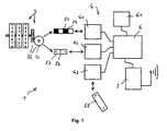
- Fig. 1 shows a schematic block diagram of the counter unit 1 according to the invention for flow meters.
- an electronic counter 4 is provided, which is triggered by means of scanning sensors 41 and 42.
- the scanning sensors emit a signal when a triggering feature 51, 52 is sensed on a moving part 31 of the mechanical counter 3.
- an opto-electronic scanning sensor 41 and a magneto-electronic scanning sensor 42 is provided.
- This combination of different types of scanning sensor makes the counter unit 1 by correlating the sensors resistant to manipulative magnetic interference (symbolized by magnet 55) from the outside.
- a magnetic 52 and an optical 51 feature are provided on a moving part 31 of the counter for evaluation.
- the opto-electronic scanning sensor 41 is designed as a reflex photoelectric sensor, wherein on the moving part 31 in particular a reflection and an absorption element 54 is evaluated as an optical feature 51.
- the moving part 31 is a gear wheel of the mechanical counter 3 in the example shown.
- the magneto-electronic scanning 42 and the manipulation sensor 43 are formed as Hall sensors.
- a magneto-electronic manipulation sensor 43 is provided for detecting interference magnetic fields penetrating the counter unit 1 (symbolized by magnet 55).
- the evaluation of the magnetoelectronic scanning sensor 42 is deactivated and the optoelectronic scanning sensor 41 is activated.
- the detected manipulation is stored in a memory 61 of the electronic counter 4 or a microprocessor 6 controlling the scanning sensors and the memory 61. Permanent connection of the reflex photoelectric sensor, a more electrical energy-consuming process - as in the prior art - used, however, so the electronic counter 4 can continue to work reliably.
- a high-frequency transmitting device 7 is provided, by means of which by the microprocessor 6, the count and other parameters, such as battery level or a detected manipulation with time, the counter unit can be transmitted.
- an in particular bidirectional optical transmitting and / or receiving device can be provided, by means of which also the counter reading and / or other parameters of the counter unit can be transmitted.
- a particularly advantageous method for operating the counter unit provides first to activate only the magneto-electronic scanning sensor until it detects a changing magnetic field - ie the permanent magnet located on the gear during the passage.
- the magneto-electronic manipulation sensor and the opto-electronic scanning sensor is activated upon detection of a changing magnetic field by the magneto-electronic scanning sensor.
- the direction of rotation of the gear, so the flow direction of the flow detected, and a check of the reliability of the applied signal by the magneto-electronic sensing sensor is done by the magneto-electronic manipulation sensor is possible.
- the timing and control of the scanning sensors and the transmitter are set to cause minimal power consumption and the meter unit can do with commercial batteries for many years.
- FIGS. 2 and 3 show in a side view ( Fig. 3 partially disassembled) a counter unit 1 according to the invention with a mechanical counter 3 with a gearbox 32 with moving part 31.
- a gear of the gear 32, the magnetic feature 52 is formed as a sunken permanent magnet 53.
- the 4 and 5 show the counter unit 1 from the FIGS. 2 and 3 in a skew supervision.
- the opto-electronic scanning sensor 41 is disposed on a board 62 below the moving part 31, the gear of the gear 32, and evaluates the reflection and absorption element mounted on the moving part as an optical feature.
- magneto-electronic scanning sensor 42 evaluates the periodically occurring by the sunk in the moving part 31 permanent magnetic field as a magnetic feature.
- the magneto-electronic manipulation sensor 43 is placed on the board 62 and detects a possibly occurring from the outside interference magnetic field.
Landscapes
- Physics & Mathematics (AREA)
- Fluid Mechanics (AREA)
- General Physics & Mathematics (AREA)
- Electromagnetism (AREA)
- Measuring Volume Flow (AREA)
- Pinball Game Machines (AREA)
- Geophysics And Detection Of Objects (AREA)
Claims (11)
- Unité de comptage (1) pour un compteur de débit volumique recevant celle-ci notamment de manière amovible, comprenant un accouplement magnétique destiné à interagir avec un dispositif hydraulique dans le compteur de débit volumique, comprenant un compteur mécanique (3) présentant des pièces mobiles (31) qui est entraîné par le biais de l'accouplement magnétique, un compteur électronique (4) étant prévu, lequel est déclenché au moyen de détecteurs à balayage (41, 42), caractérisée en ce qu'il est prévu un détecteur à balayage optoélectronique (41) et un détecteur à balayage magnéto-électronique (42) qui interprètent une caractéristique magnétique (52) et une caractéristique optique (51) sur une pièce mobile (31) du compteur mécanique (3).
- Unité de comptage selon la revendication 1, caractérisée en ce qu'il est prévu un détecteur de manipulation magnéto-électronique (43) pour détecter les champs magnétiques parasites qui traversent l'unité de comptage (1).
- Unité de comptage selon la revendication 1 ou 2, caractérisée en ce que le détecteur à balayage magnéto-électronique (42) est réalisé sous la forme d'un capteur à effet Hall qui interprète en tant que caractéristique (52) un aimant permanent (53) prévu dans ou sur la pièce mobile (31).
- Unité de comptage selon la revendication 2 ou 3, caractérisée en ce que le détecteur de manipulation magnéto-électronique (43) est réalisé sous la forme d'un capteur à effet Hall.
- Unité de comptage selon l'une des revendications 1 à 4, caractérisée en ce que le détecteur à balayage optoélectronique (41) est réalisé sous la forme d'une barrière photoélectrique à réflexion, un élément de réflexion et d'absorption (54) étant notamment interprété comme caractéristique optique (51) sur la pièce mobile (31).
- Unité de comptage selon l'une des revendications 1 à 5, caractérisée en ce que la pièce mobile (31) est une roue d'engrenage du compteur mécanique (3).
- Unité de comptage selon l'une des revendications 1 à 6, caractérisée en ce qu'il est prévu un dispositif émetteur à haute fréquence (7) au moyen duquel peuvent être transmis la valeur comptée et/ou d'autres paramètres de l'unité de comptage.
- Unité de comptage selon l'une des revendications 1 à 7, caractérisée en ce qu'il est prévu un dispositif émetteur et/ou récepteur optique notamment bidirectionnel au moyen duquel peuvent être transmis la valeur comptée et/ou d'autres paramètres de l'unité de comptage.
- Unité de comptage selon l'une des revendications 1 à 8, caractérisée en ce qu'il est prévu un microprocesseur (6) qui interprète le compteur électronique (4) et/ou les détecteurs (41 à 43) et/ou commande le dispositif émetteur à haute fréquence (7) et/ou le dispositif émetteur et/ou récepteur optique.
- Procédé pour acquérir un débit volumique au moyen d'une unité de comptage selon l'une des revendications 1 à 9, caractérisé par les étapes :- Activation du détecteur à balayage magnéto-électronique (42) seulement jusqu'à ce que celui-ci détecte un champ magnétique qui varie,- Activation en plus du détecteur de manipulation magnéto-électronique (43) ainsi que du détecteur à balayage optoélectronique (41) en cas de détection d'un champ magnétique qui varie par le détecteur à balayage magnéto-électronique (42),- Interprétation du détecteur de manipulation (43),- Détection du sens de rotation de la pièce mobile (31) au moyen du détecteur à balayage optoélectronique (41) et du détecteur à balayage magnéto-électronique (42) en vue de déterminer le sens du débit volumique à travers le compteur de débit volumique,- Désactivation du détecteur à balayage optoélectronique (41).
- Procédé selon la revendication 10, caractérisé en ce qu'en cas de détection de champs magnétiques parasites, l'interprétation du détecteur à balayage magnéto-électronique (42) est désactivée et le détecteur à balayage optoélectronique (41) est activé et/ou la manipulation détectée est enregistrée dans une mémoire (61) du compteur électronique ou du microprocesseur (6).
Priority Applications (3)
| Application Number | Priority Date | Filing Date | Title |
|---|---|---|---|
| DE502006000999T DE502006000999D1 (de) | 2006-08-15 | 2006-08-15 | Betrugssicherer Flüssigkeitsströmungsmesser |
| EP06016980A EP1890116B1 (fr) | 2006-08-15 | 2006-08-15 | Compteur de liquides infraudable |
| AT06016980T ATE399308T1 (de) | 2006-08-15 | 2006-08-15 | Betrugssicherer flüssigkeitsströmungsmesser |
Applications Claiming Priority (1)
| Application Number | Priority Date | Filing Date | Title |
|---|---|---|---|
| EP06016980A EP1890116B1 (fr) | 2006-08-15 | 2006-08-15 | Compteur de liquides infraudable |
Publications (2)
| Publication Number | Publication Date |
|---|---|
| EP1890116A1 EP1890116A1 (fr) | 2008-02-20 |
| EP1890116B1 true EP1890116B1 (fr) | 2008-06-25 |
Family
ID=37906889
Family Applications (1)
| Application Number | Title | Priority Date | Filing Date |
|---|---|---|---|
| EP06016980A Active EP1890116B1 (fr) | 2006-08-15 | 2006-08-15 | Compteur de liquides infraudable |
Country Status (3)
| Country | Link |
|---|---|
| EP (1) | EP1890116B1 (fr) |
| AT (1) | ATE399308T1 (fr) |
| DE (1) | DE502006000999D1 (fr) |
Cited By (1)
| Publication number | Priority date | Publication date | Assignee | Title |
|---|---|---|---|---|
| EP3978932A1 (fr) * | 2020-10-01 | 2022-04-06 | Robert Bosch GmbH | Capteur de mouvement destiné à la détection d'un mouvement d'un objet en mouvement, système doté d'un tel capteur de mouvement et procédé de vérification d'une manipulation d'un tel capteur de mouvement |
Families Citing this family (3)
| Publication number | Priority date | Publication date | Assignee | Title |
|---|---|---|---|---|
| DE102008063434A1 (de) * | 2008-12-31 | 2010-07-08 | Elster Meßtechnik GmbH | Elektronisches Zählerboard und Volumenzähler für Flüssigkeiten mit einem solchen Zählerboard |
| CN102889908A (zh) * | 2011-07-19 | 2013-01-23 | 工量国际企业股份有限公司 | 磁感应流体计量装置的防磁干扰关断系统及其操作方法 |
| DE102013219796A1 (de) * | 2013-09-30 | 2015-04-16 | Continental Automotive Gmbh | Impulsgeber für eine Vorrichtung zur Betriebsdatenerfassung, Getriebeanordnung mit einem Impulsgeber, Tachographenanordnung sowie Verfahren zur Erzeugung eines Ausgabesignals für eine Vorrichtung zur Betriebsdatenerfassung in einem Fahrzeug |
Family Cites Families (3)
| Publication number | Priority date | Publication date | Assignee | Title |
|---|---|---|---|---|
| GB2123556B (en) * | 1982-07-06 | 1985-11-20 | Metal Ind Limited | Flowmeters using electric switches |
| US5086292A (en) * | 1989-10-31 | 1992-02-04 | Iris Systems Inc. | Tamper detection device for utility meter |
| US7135986B2 (en) * | 2003-06-13 | 2006-11-14 | Arad Measuring Technologies Ltd. | Meter register having an encoder for measuring material flow and an algorithm to selectively block signal transmission |
-
2006
- 2006-08-15 EP EP06016980A patent/EP1890116B1/fr active Active
- 2006-08-15 AT AT06016980T patent/ATE399308T1/de not_active IP Right Cessation
- 2006-08-15 DE DE502006000999T patent/DE502006000999D1/de active Active
Cited By (1)
| Publication number | Priority date | Publication date | Assignee | Title |
|---|---|---|---|---|
| EP3978932A1 (fr) * | 2020-10-01 | 2022-04-06 | Robert Bosch GmbH | Capteur de mouvement destiné à la détection d'un mouvement d'un objet en mouvement, système doté d'un tel capteur de mouvement et procédé de vérification d'une manipulation d'un tel capteur de mouvement |
Also Published As
| Publication number | Publication date |
|---|---|
| DE502006000999D1 (de) | 2008-08-07 |
| ATE399308T1 (de) | 2008-07-15 |
| EP1890116A1 (fr) | 2008-02-20 |
Similar Documents
| Publication | Publication Date | Title |
|---|---|---|
| DE60024692T2 (de) | Elektrische Servolenkeinrichtung | |
| EP1225427B1 (fr) | Capteur de rotation | |
| DE4428996C2 (de) | Wasserzähler | |
| DE102009029431A1 (de) | Multiturn-Drehgeber | |
| EP2887072A1 (fr) | Boîte de vitesses détectant la vitesse pour un véhicule automobile | |
| EP1890116B1 (fr) | Compteur de liquides infraudable | |
| EP2622153B1 (fr) | Dispositif capteur présentant enregistrement du sens de rotation | |
| EP2370792B1 (fr) | Compteur volumétrique de liquides | |
| DE202004009047U1 (de) | Positionsgeber für Tore | |
| EP3361221A1 (fr) | Capteur de détermination de position d'un système d'entraînement | |
| DE10214418A1 (de) | Volumenzähler zum Messen eines Flüssigkeitsvolumens | |
| DE19920393A1 (de) | Anordnung zum Bestimmen eines Volumens eines Gasstroms | |
| EP3214416A1 (fr) | Débitmètre, en particulier pour utilisation soumise à obligation d'étalonnage | |
| EP0462435B1 (fr) | Arrangement pour détecter la vitesse de rotation d'une pièce en rotation | |
| DE102005051159B4 (de) | Verwendung eines Kommunikationsmoduls zum Einsetzen in einen Zähler und Kommunikationsmodul | |
| DE202020107490U1 (de) | Anordnung zur Erfassung des Warmwasserverbrauches für ein Wasserversorgungssystem mit einer Zirkulationsanlage und mehreren Wasserentnahmestellen | |
| EP1371542A1 (fr) | Capteur d'angle pour la détection de l'angle de braquage d'un système de direction | |
| EP3978932B1 (fr) | Capteur de mouvement destiné à la détection d'un mouvement d'un objet en mouvement, système doté d'un tel capteur de mouvement et procédé de vérification d'une manipulation d'un tel capteur de mouvement | |
| DE102007042757A1 (de) | Verfahren und Vorrichtung zur Stellungsanzeige von hydraulisch betätigten Armaturen | |
| DE4423461A1 (de) | Volumeter | |
| WO2015044241A1 (fr) | Générateur d'impulsions pour dispositif d'acquisition de données de fonctionnement, système de boîte de vitesses équipé d'un générateur d'impulsions, système de tachygraphe ainsi que procédé de génération d'un signal de sortie pour un dispositif d'acquisition de données de fonctionnement dans un véhicule | |
| DE3339033C2 (de) | Kontrollvorrichtung für ein an einer Fahrzeugradnabe befestigbares Instrument zur Registrierung der vom Fahrzeug zurückgelegten Wegstrecke | |
| DE102020001833A1 (de) | Getriebliche Anordnung mit einer Messeinrichtung | |
| EP0317819A2 (fr) | Mécanisme compteur à rouleaux, en particulier pour compteur à gaz | |
| DE102020001983A1 (de) | Gebäudeabschlussantriebseinheit |
Legal Events
| Date | Code | Title | Description |
|---|---|---|---|
| PUAI | Public reference made under article 153(3) epc to a published international application that has entered the european phase |
Free format text: ORIGINAL CODE: 0009012 |
|
| 17P | Request for examination filed |
Effective date: 20070725 |
|
| AK | Designated contracting states |
Kind code of ref document: A1 Designated state(s): AT BE BG CH CY CZ DE DK EE ES FI FR GB GR HU IE IS IT LI LT LU LV MC NL PL PT RO SE SI SK TR |
|
| AX | Request for extension of the european patent |
Extension state: AL BA HR MK YU |
|
| GRAP | Despatch of communication of intention to grant a patent |
Free format text: ORIGINAL CODE: EPIDOSNIGR1 |
|
| GRAS | Grant fee paid |
Free format text: ORIGINAL CODE: EPIDOSNIGR3 |
|
| GRAA | (expected) grant |
Free format text: ORIGINAL CODE: 0009210 |
|
| AK | Designated contracting states |
Kind code of ref document: B1 Designated state(s): AT BE BG CH CY CZ DE DK EE ES FI FR GB GR HU IE IS IT LI LT LU LV MC NL PL PT RO SE SI SK TR |
|
| REG | Reference to a national code |
Ref country code: GB Ref legal event code: FG4D Free format text: NOT ENGLISH |
|
| REG | Reference to a national code |
Ref country code: CH Ref legal event code: EP |
|
| REF | Corresponds to: |
Ref document number: 502006000999 Country of ref document: DE Date of ref document: 20080807 Kind code of ref document: P |
|
| REG | Reference to a national code |
Ref country code: IE Ref legal event code: FG4D Free format text: LANGUAGE OF EP DOCUMENT: GERMAN |
|
| AKX | Designation fees paid |
Designated state(s): AT BE BG CH CY CZ DE DK EE ES FI FR GB GR HU IE IS IT LI LT LU LV MC NL PL PT RO SE SI SK TR |
|
| PG25 | Lapsed in a contracting state [announced via postgrant information from national office to epo] |
Ref country code: FI Free format text: LAPSE BECAUSE OF FAILURE TO SUBMIT A TRANSLATION OF THE DESCRIPTION OR TO PAY THE FEE WITHIN THE PRESCRIBED TIME-LIMIT Effective date: 20080625 Ref country code: SI Free format text: LAPSE BECAUSE OF FAILURE TO SUBMIT A TRANSLATION OF THE DESCRIPTION OR TO PAY THE FEE WITHIN THE PRESCRIBED TIME-LIMIT Effective date: 20080625 |
|
| PG25 | Lapsed in a contracting state [announced via postgrant information from national office to epo] |
Ref country code: NL Free format text: LAPSE BECAUSE OF FAILURE TO SUBMIT A TRANSLATION OF THE DESCRIPTION OR TO PAY THE FEE WITHIN THE PRESCRIBED TIME-LIMIT Effective date: 20080625 Ref country code: PL Free format text: LAPSE BECAUSE OF FAILURE TO SUBMIT A TRANSLATION OF THE DESCRIPTION OR TO PAY THE FEE WITHIN THE PRESCRIBED TIME-LIMIT Effective date: 20080625 Ref country code: LV Free format text: LAPSE BECAUSE OF FAILURE TO SUBMIT A TRANSLATION OF THE DESCRIPTION OR TO PAY THE FEE WITHIN THE PRESCRIBED TIME-LIMIT Effective date: 20080625 |
|
| NLV1 | Nl: lapsed or annulled due to failure to fulfill the requirements of art. 29p and 29m of the patents act | ||
| PG25 | Lapsed in a contracting state [announced via postgrant information from national office to epo] |
Ref country code: LT Free format text: LAPSE BECAUSE OF FAILURE TO SUBMIT A TRANSLATION OF THE DESCRIPTION OR TO PAY THE FEE WITHIN THE PRESCRIBED TIME-LIMIT Effective date: 20080625 Ref country code: IS Free format text: LAPSE BECAUSE OF FAILURE TO SUBMIT A TRANSLATION OF THE DESCRIPTION OR TO PAY THE FEE WITHIN THE PRESCRIBED TIME-LIMIT Effective date: 20081025 Ref country code: CZ Free format text: LAPSE BECAUSE OF FAILURE TO SUBMIT A TRANSLATION OF THE DESCRIPTION OR TO PAY THE FEE WITHIN THE PRESCRIBED TIME-LIMIT Effective date: 20080625 Ref country code: SE Free format text: LAPSE BECAUSE OF FAILURE TO SUBMIT A TRANSLATION OF THE DESCRIPTION OR TO PAY THE FEE WITHIN THE PRESCRIBED TIME-LIMIT Effective date: 20080925 |
|
| PG25 | Lapsed in a contracting state [announced via postgrant information from national office to epo] |
Ref country code: ES Free format text: LAPSE BECAUSE OF FAILURE TO SUBMIT A TRANSLATION OF THE DESCRIPTION OR TO PAY THE FEE WITHIN THE PRESCRIBED TIME-LIMIT Effective date: 20081006 Ref country code: PT Free format text: LAPSE BECAUSE OF FAILURE TO SUBMIT A TRANSLATION OF THE DESCRIPTION OR TO PAY THE FEE WITHIN THE PRESCRIBED TIME-LIMIT Effective date: 20081125 Ref country code: SK Free format text: LAPSE BECAUSE OF FAILURE TO SUBMIT A TRANSLATION OF THE DESCRIPTION OR TO PAY THE FEE WITHIN THE PRESCRIBED TIME-LIMIT Effective date: 20080625 Ref country code: RO Free format text: LAPSE BECAUSE OF FAILURE TO SUBMIT A TRANSLATION OF THE DESCRIPTION OR TO PAY THE FEE WITHIN THE PRESCRIBED TIME-LIMIT Effective date: 20080625 |
|
| REG | Reference to a national code |
Ref country code: IE Ref legal event code: FD4D |
|
| PG25 | Lapsed in a contracting state [announced via postgrant information from national office to epo] |
Ref country code: MC Free format text: LAPSE BECAUSE OF NON-PAYMENT OF DUE FEES Effective date: 20080831 |
|
| PG25 | Lapsed in a contracting state [announced via postgrant information from national office to epo] |
Ref country code: IE Free format text: LAPSE BECAUSE OF FAILURE TO SUBMIT A TRANSLATION OF THE DESCRIPTION OR TO PAY THE FEE WITHIN THE PRESCRIBED TIME-LIMIT Effective date: 20080625 Ref country code: DK Free format text: LAPSE BECAUSE OF FAILURE TO SUBMIT A TRANSLATION OF THE DESCRIPTION OR TO PAY THE FEE WITHIN THE PRESCRIBED TIME-LIMIT Effective date: 20080625 Ref country code: EE Free format text: LAPSE BECAUSE OF FAILURE TO SUBMIT A TRANSLATION OF THE DESCRIPTION OR TO PAY THE FEE WITHIN THE PRESCRIBED TIME-LIMIT Effective date: 20080625 Ref country code: BG Free format text: LAPSE BECAUSE OF FAILURE TO SUBMIT A TRANSLATION OF THE DESCRIPTION OR TO PAY THE FEE WITHIN THE PRESCRIBED TIME-LIMIT Effective date: 20080925 |
|
| PLBE | No opposition filed within time limit |
Free format text: ORIGINAL CODE: 0009261 |
|
| STAA | Information on the status of an ep patent application or granted ep patent |
Free format text: STATUS: NO OPPOSITION FILED WITHIN TIME LIMIT |
|
| 26N | No opposition filed |
Effective date: 20090326 |
|
| PG25 | Lapsed in a contracting state [announced via postgrant information from national office to epo] |
Ref country code: BE Free format text: LAPSE BECAUSE OF NON-PAYMENT OF DUE FEES Effective date: 20080831 |
|
| PG25 | Lapsed in a contracting state [announced via postgrant information from national office to epo] |
Ref country code: IT Free format text: LAPSE BECAUSE OF FAILURE TO SUBMIT A TRANSLATION OF THE DESCRIPTION OR TO PAY THE FEE WITHIN THE PRESCRIBED TIME-LIMIT Effective date: 20080625 |
|
| PG25 | Lapsed in a contracting state [announced via postgrant information from national office to epo] |
Ref country code: AT Free format text: LAPSE BECAUSE OF NON-PAYMENT OF DUE FEES Effective date: 20080815 |
|
| PG25 | Lapsed in a contracting state [announced via postgrant information from national office to epo] |
Ref country code: LU Free format text: LAPSE BECAUSE OF NON-PAYMENT OF DUE FEES Effective date: 20080815 Ref country code: HU Free format text: LAPSE BECAUSE OF FAILURE TO SUBMIT A TRANSLATION OF THE DESCRIPTION OR TO PAY THE FEE WITHIN THE PRESCRIBED TIME-LIMIT Effective date: 20081226 Ref country code: CY Free format text: LAPSE BECAUSE OF FAILURE TO SUBMIT A TRANSLATION OF THE DESCRIPTION OR TO PAY THE FEE WITHIN THE PRESCRIBED TIME-LIMIT Effective date: 20080625 |
|
| PG25 | Lapsed in a contracting state [announced via postgrant information from national office to epo] |
Ref country code: TR Free format text: LAPSE BECAUSE OF FAILURE TO SUBMIT A TRANSLATION OF THE DESCRIPTION OR TO PAY THE FEE WITHIN THE PRESCRIBED TIME-LIMIT Effective date: 20080625 |
|
| PG25 | Lapsed in a contracting state [announced via postgrant information from national office to epo] |
Ref country code: GR Free format text: LAPSE BECAUSE OF FAILURE TO SUBMIT A TRANSLATION OF THE DESCRIPTION OR TO PAY THE FEE WITHIN THE PRESCRIBED TIME-LIMIT Effective date: 20080926 |
|
| REG | Reference to a national code |
Ref country code: CH Ref legal event code: PL |
|
| GBPC | Gb: european patent ceased through non-payment of renewal fee |
Effective date: 20100815 |
|
| PG25 | Lapsed in a contracting state [announced via postgrant information from national office to epo] |
Ref country code: LI Free format text: LAPSE BECAUSE OF NON-PAYMENT OF DUE FEES Effective date: 20100831 Ref country code: CH Free format text: LAPSE BECAUSE OF NON-PAYMENT OF DUE FEES Effective date: 20100831 |
|
| PG25 | Lapsed in a contracting state [announced via postgrant information from national office to epo] |
Ref country code: GB Free format text: LAPSE BECAUSE OF NON-PAYMENT OF DUE FEES Effective date: 20100815 |
|
| REG | Reference to a national code |
Ref country code: FR Ref legal event code: PLFP Year of fee payment: 11 |
|
| REG | Reference to a national code |
Ref country code: FR Ref legal event code: PLFP Year of fee payment: 12 |
|
| REG | Reference to a national code |
Ref country code: FR Ref legal event code: PLFP Year of fee payment: 13 |
|
| P01 | Opt-out of the competence of the unified patent court (upc) registered |
Effective date: 20230606 |
|
| PGFP | Annual fee paid to national office [announced via postgrant information from national office to epo] |
Ref country code: DE Payment date: 20250601 Year of fee payment: 20 |
|
| PGFP | Annual fee paid to national office [announced via postgrant information from national office to epo] |
Ref country code: FR Payment date: 20250821 Year of fee payment: 20 |