EP3214896A1 - Élément chauffant en céramique et son procédé de fabrication - Google Patents
Élément chauffant en céramique et son procédé de fabrication Download PDFInfo
- Publication number
- EP3214896A1 EP3214896A1 EP15855716.5A EP15855716A EP3214896A1 EP 3214896 A1 EP3214896 A1 EP 3214896A1 EP 15855716 A EP15855716 A EP 15855716A EP 3214896 A1 EP3214896 A1 EP 3214896A1
- Authority
- EP
- European Patent Office
- Prior art keywords
- flange
- glass
- glass material
- ceramic
- heater body
- Prior art date
- Legal status (The legal status is an assumption and is not a legal conclusion. Google has not performed a legal analysis and makes no representation as to the accuracy of the status listed.)
- Granted
Links
Images


Classifications
-
- H—ELECTRICITY
- H05—ELECTRIC TECHNIQUES NOT OTHERWISE PROVIDED FOR
- H05B—ELECTRIC HEATING; ELECTRIC LIGHT SOURCES NOT OTHERWISE PROVIDED FOR; CIRCUIT ARRANGEMENTS FOR ELECTRIC LIGHT SOURCES, IN GENERAL
- H05B3/00—Ohmic-resistance heating
- H05B3/40—Heating elements having the shape of rods or tubes
- H05B3/42—Heating elements having the shape of rods or tubes non-flexible
- H05B3/48—Heating elements having the shape of rods or tubes non-flexible heating conductor embedded in insulating material
-
- H—ELECTRICITY
- H05—ELECTRIC TECHNIQUES NOT OTHERWISE PROVIDED FOR
- H05B—ELECTRIC HEATING; ELECTRIC LIGHT SOURCES NOT OTHERWISE PROVIDED FOR; CIRCUIT ARRANGEMENTS FOR ELECTRIC LIGHT SOURCES, IN GENERAL
- H05B3/00—Ohmic-resistance heating
- H05B3/02—Details
- H05B3/06—Heater elements structurally combined with coupling elements or holders
-
- H—ELECTRICITY
- H05—ELECTRIC TECHNIQUES NOT OTHERWISE PROVIDED FOR
- H05B—ELECTRIC HEATING; ELECTRIC LIGHT SOURCES NOT OTHERWISE PROVIDED FOR; CIRCUIT ARRANGEMENTS FOR ELECTRIC LIGHT SOURCES, IN GENERAL
- H05B1/00—Details of electric heating devices
- H05B1/02—Automatic switching arrangements specially adapted to apparatus ; Control of heating devices
- H05B1/0227—Applications
- H05B1/0297—Heating of fluids for non specified applications
-
- H—ELECTRICITY
- H05—ELECTRIC TECHNIQUES NOT OTHERWISE PROVIDED FOR
- H05B—ELECTRIC HEATING; ELECTRIC LIGHT SOURCES NOT OTHERWISE PROVIDED FOR; CIRCUIT ARRANGEMENTS FOR ELECTRIC LIGHT SOURCES, IN GENERAL
- H05B3/00—Ohmic-resistance heating
- H05B3/10—Heating elements characterised by the composition or nature of the materials or by the arrangement of the conductor
- H05B3/12—Heating elements characterised by the composition or nature of the materials or by the arrangement of the conductor characterised by the composition or nature of the conductive material
- H05B3/14—Heating elements characterised by the composition or nature of the materials or by the arrangement of the conductor characterised by the composition or nature of the conductive material the material being non-metallic
- H05B3/141—Conductive ceramics, e.g. metal oxides, metal carbides, barium titanate, ferrites, zirconia, vitrous compounds
-
- H—ELECTRICITY
- H05—ELECTRIC TECHNIQUES NOT OTHERWISE PROVIDED FOR
- H05B—ELECTRIC HEATING; ELECTRIC LIGHT SOURCES NOT OTHERWISE PROVIDED FOR; CIRCUIT ARRANGEMENTS FOR ELECTRIC LIGHT SOURCES, IN GENERAL
- H05B3/00—Ohmic-resistance heating
- H05B3/10—Heating elements characterised by the composition or nature of the materials or by the arrangement of the conductor
- H05B3/18—Heating elements characterised by the composition or nature of the materials or by the arrangement of the conductor the conductor being embedded in an insulating material
-
- H—ELECTRICITY
- H05—ELECTRIC TECHNIQUES NOT OTHERWISE PROVIDED FOR
- H05B—ELECTRIC HEATING; ELECTRIC LIGHT SOURCES NOT OTHERWISE PROVIDED FOR; CIRCUIT ARRANGEMENTS FOR ELECTRIC LIGHT SOURCES, IN GENERAL
- H05B3/00—Ohmic-resistance heating
- H05B3/20—Heating elements having extended surface area substantially in a two-dimensional [2D] plane, e.g. plate-heater
- H05B3/34—Heating elements having extended surface area substantially in a two-dimensional [2D] plane, e.g. plate-heater flexible, e.g. heating nets or webs
-
- H—ELECTRICITY
- H05—ELECTRIC TECHNIQUES NOT OTHERWISE PROVIDED FOR
- H05B—ELECTRIC HEATING; ELECTRIC LIGHT SOURCES NOT OTHERWISE PROVIDED FOR; CIRCUIT ARRANGEMENTS FOR ELECTRIC LIGHT SOURCES, IN GENERAL
- H05B3/00—Ohmic-resistance heating
- H05B3/40—Heating elements having the shape of rods or tubes
- H05B3/42—Heating elements having the shape of rods or tubes non-flexible
- H05B3/46—Heating elements having the shape of rods or tubes non-flexible heating conductor mounted on insulating base
-
- H—ELECTRICITY
- H05—ELECTRIC TECHNIQUES NOT OTHERWISE PROVIDED FOR
- H05B—ELECTRIC HEATING; ELECTRIC LIGHT SOURCES NOT OTHERWISE PROVIDED FOR; CIRCUIT ARRANGEMENTS FOR ELECTRIC LIGHT SOURCES, IN GENERAL
- H05B3/00—Ohmic-resistance heating
- H05B3/40—Heating elements having the shape of rods or tubes
- H05B3/42—Heating elements having the shape of rods or tubes non-flexible
- H05B3/48—Heating elements having the shape of rods or tubes non-flexible heating conductor embedded in insulating material
- H05B3/52—Apparatus or processes for filling or compressing insulating material in tubes
-
- H—ELECTRICITY
- H05—ELECTRIC TECHNIQUES NOT OTHERWISE PROVIDED FOR
- H05B—ELECTRIC HEATING; ELECTRIC LIGHT SOURCES NOT OTHERWISE PROVIDED FOR; CIRCUIT ARRANGEMENTS FOR ELECTRIC LIGHT SOURCES, IN GENERAL
- H05B3/00—Ohmic-resistance heating
- H05B3/78—Heating arrangements specially adapted for immersion heating
-
- H—ELECTRICITY
- H05—ELECTRIC TECHNIQUES NOT OTHERWISE PROVIDED FOR
- H05B—ELECTRIC HEATING; ELECTRIC LIGHT SOURCES NOT OTHERWISE PROVIDED FOR; CIRCUIT ARRANGEMENTS FOR ELECTRIC LIGHT SOURCES, IN GENERAL
- H05B2203/00—Aspects relating to Ohmic resistive heating covered by group H05B3/00
- H05B2203/002—Heaters using a particular layout for the resistive material or resistive elements
- H05B2203/003—Heaters using a particular layout for the resistive material or resistive elements using serpentine layout
-
- H—ELECTRICITY
- H05—ELECTRIC TECHNIQUES NOT OTHERWISE PROVIDED FOR
- H05B—ELECTRIC HEATING; ELECTRIC LIGHT SOURCES NOT OTHERWISE PROVIDED FOR; CIRCUIT ARRANGEMENTS FOR ELECTRIC LIGHT SOURCES, IN GENERAL
- H05B2203/00—Aspects relating to Ohmic resistive heating covered by group H05B3/00
- H05B2203/013—Heaters using resistive films or coatings
-
- H—ELECTRICITY
- H05—ELECTRIC TECHNIQUES NOT OTHERWISE PROVIDED FOR
- H05B—ELECTRIC HEATING; ELECTRIC LIGHT SOURCES NOT OTHERWISE PROVIDED FOR; CIRCUIT ARRANGEMENTS FOR ELECTRIC LIGHT SOURCES, IN GENERAL
- H05B2203/00—Aspects relating to Ohmic resistive heating covered by group H05B3/00
- H05B2203/016—Heaters using particular connecting means
-
- H—ELECTRICITY
- H05—ELECTRIC TECHNIQUES NOT OTHERWISE PROVIDED FOR
- H05B—ELECTRIC HEATING; ELECTRIC LIGHT SOURCES NOT OTHERWISE PROVIDED FOR; CIRCUIT ARRANGEMENTS FOR ELECTRIC LIGHT SOURCES, IN GENERAL
- H05B2203/00—Aspects relating to Ohmic resistive heating covered by group H05B3/00
- H05B2203/017—Manufacturing methods or apparatus for heaters
-
- H—ELECTRICITY
- H05—ELECTRIC TECHNIQUES NOT OTHERWISE PROVIDED FOR
- H05B—ELECTRIC HEATING; ELECTRIC LIGHT SOURCES NOT OTHERWISE PROVIDED FOR; CIRCUIT ARRANGEMENTS FOR ELECTRIC LIGHT SOURCES, IN GENERAL
- H05B2203/00—Aspects relating to Ohmic resistive heating covered by group H05B3/00
- H05B2203/021—Heaters specially adapted for heating liquids
Definitions
- the present invention relates to a ceramic heater for use in a warm water washing toilet seat, a fan heater, an electric water heater, a 24-hour bath etc., and to a method for manufacturing the ceramic heater.
- the expression "24-hour bath” refers to a circulation type bath capable of circulating hot water between a bathtub and a heating unit so as to, when the temperature of the circulated hot water becomes lowered, heat the circulated hot water as needed and thereby allow bathing at all times.
- a warm water washing toilet seat has a heat exchange unit equipped with a resin container (as a heat exchanger).
- a heat exchanger equipped with a resin container (as a heat exchanger).
- a long pipe-shaped ceramic heater is disposed to heat washing water in the heat exchanger.
- a ceramic heater As such a ceramic heater, there is known a ceramic heater of the type having a cylindrical ceramic heater body and an annular plate-shaped ceramic flange fitted around the heater body and bonded to the heater body by a glass material.
- the ceramic heater body and the metal flange need to be brazed together by forming a metallized layer on a bonding area of the heater body, applying a plating layer to the metalized layer, applying a plating layer to a bonding area of the flange, and then, bonding the plating layer of the heater body to the plating layer of the flange via the brazing material.
- the manufacturing of the ceramic heater requires much expense in time and effort so that it is not easy to manufacture the ceramic heater.
- the glass material is filled in the glass accumulation region of the concave part of the flange and is fused to the heater body and the flange.
- the ceramic heater is thus manufactured by filling the glass accumulation region with the glass material and fusing the glass material to the heater body and the flange. It is therefore possible to easily manufacture the ceramic heater as compared with the case of using a conventional brazing bonding process.
- the glass material in the glass accumulation region is fused to an inner circumferential surface of the flange and an outer circumferential surface of the heater body over a wide area along the axial direction as compared with the case where a (conventional) plate-shaped flange is bonded only at a narrow inner circumferential surface of a through hole thereof to the heater body. It is therefore possible to effectively achieve the high air tightness and bonding strength between the heater body and the flange.
- glass accumulation region refers to a region of the concave part in which the glass material can be accumulated (i.e. in which the glass material is filled and accumulated).
- the thermal expansion coefficient of the metal material of the flange is higher than the thermal expansion coefficient of the ceramic material and the thermal expansion coefficient of the glass material of the heater body
- stress is exerted by the outside flange onto the inside glass material and heater body in response to decrease from the temperature of fusing of the glass material (i.e. fusing temperature) to e.g. ambient temperature. It is thus possible to effectively improve the air tightness and bonding strength between the heater body and the flange.
- thermal expansion coefficient refers to a thermal coefficient of expansion at the time of fusing of the glass material.
- the thermal expansion coefficient of the metal material of the flange may be set to within the range of 100 ⁇ 10 -7 to 200 ⁇ 10 -7 /K.
- the thermal expansion coefficient of the ceramic material of the heater body may be set to within the range of 50 ⁇ 10 -7 to 90 ⁇ 10 -7 /K.
- a thermal expansion coefficient of the glass material is higher than the thermal expansion coefficient of the ceramic material. In this case, it is possible to obtain further improvements in air tightness and bonding strength.
- the flange with which the glass material is in contact is heated in the same manner.
- Cr can be deposited at the surface of the flange.
- the metal material of the flange can be either a simple metal substance or a metal alloy.
- a metal material stainless steel such as SUS 304 or SUS 430 (according to JIS) is usable.
- SUS 304 or SUS 430 (according to JIS) is usable.
- the ceramic material of the heater body there can be used alumina, aluminum nitride, silicon nitride, zirconia, mullite or the like.
- the heater body may have a heating element formed of e.g. tungsten.
- the heater body may be of the type containing the ceramic material as a main component.
- the glass accumulation region in which the glass material is filled and accumulated may be formed with a depth of 1 to 20 mm (in the axial direction).
- the glass material may be provided with a depth of 2 mm or more.
- the glass material there can be used B 2 O 3 -SiO 2 -Al 2 O 3 glass, SiO 2 -Na 2 O glass, SiO 2 -PbO glass, SiO 2 -Al 2 O 3 -BaO glass or the like.
- the ceramic heater according to the first embodiment is designed for use in an exhaust exchanger of a heat exchange unit of e.g. a warm water washing toilet seat so as to heat washing water.
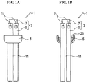
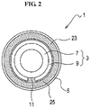
- the ceramic heater 1 As shown in FIGS. 1A, 1B and 2 , the ceramic heater 1 according to the first embodiment includes a cylindrical ceramic heater body 3 and an annular metal flange 5 fitted around the heater body 3.
- the heater body 3 has a ceramic tube 7 formed with e.g. an outer diameter ⁇ of 10 mm, an inner diameter ⁇ of 8 mm and a length of 65 mm and a ceramic layer 9 formed with e.g. a thickness of 0.5 mm and a length of 60 mm so as to cover almost the entire outer circumference of the ceramic tube 7.
- the ceramic tube 7 is however not entirely covered by the ceramic layer 9.
- a groove (slit) 11 of e.g. 1 mm width and 0.5 mm depth is formed in the ceramic layer 9 along an axial direction of the heater body.
- Both of the ceramic tube 7 and the ceramic layer 9 are made of alumina having a thermal expansion coefficient of e.g. 70 ⁇ 10 -7 /K, which falls within the range of 50 ⁇ 10 -7 to 90 ⁇ 10 -7 /K (as measured at 30 to 380°C; the same applies to the following).
- a serpentine heating element 11 and a pair of inner terminals 13 are formed on an inner circumferential surface of the ceramic layer 9 (closer to the ceramic tube 7) or inside the ceramic layer 9. Further, outer terminals 15 (see FIGS. 1A and 1B ) are formed on an outer circumferential surface of an end portion of the ceramic layer 9. The inner terminals 13 are electrically connected to the outer terminals 15 via through holes or via holes (not shown).
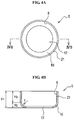
- the flange 5 is an annular member of e.g. stainless steel and is formed into a concave shape (cup-like shape) by bending a center portion of a plate material toward one side (i.e. the lower side of FIG. 4B ).
- the flange 5 is formed from a plate of e.g. 1 mm thickness such that a part of the flange is concave to define a concave part 6.
- One open end side (i.e. the upper side of FIG. 4B ) of the concave part 6 is e.g. 16 mm in inner diameter ⁇ ; and the other open end side of the concave part 6 (i.e. the outer diameter of a through hole 17) is e.g. 12 mm in inner diameter ⁇ .
- the total height H1 of the flange 5 (in the vertical direction of FIG. 4B ) is set to e.g. 6 mm.
- the flange 5 includes a bottom portion 19 curved with a radius r (e.g. 1.5 mm) and a cylindrical lateral portion 21 extending upward (i.e. in a direction perpendicular to the axial direction) from the bottom portion 19.
- the height H2 of the bottom portion 19 is set to 1.5 mm; and the height H3 of the lateral portion 21 is set to 4.5 mm.
- radius r used herein refers to a radius of the curved bottom portion in a cross section taken along the axial direction.
- the flange 5 has a thermal expansion coefficient of 178 ⁇ 10 -7 /K (at 30 to 380°C) in the case where the flange 5 is made of SUS 304 (containing Fe, Ni and Cr as main components).
- the flange 5 has a thermal expansion coefficient of 110 ⁇ 10 -7 /K (at 30 to 380°C) in the case where the flange 5 is made of SUS 430 (containing Fe and Cr as main components). In either case, the thermal expansion coefficient of the flange 5 falls within the range of 100 ⁇ 10 -7 to 200 ⁇ 10 -7 /K (at 30 to 380°C).
- a space surrounded by an outer circumferential surface of the heater body 3 and an inner circumferential surface of the flange 5 within the concave part 6 of the flange 5 is adapted as a glass accumulation portion 25 filled with a glass material 23 as shown by enlargement in FIG. 5 .
- the glass material 23 is indicated by fine dots in FIGS. 1A, 1B and 2 .
- the height H4 of the glass accumulation region 25 (in the vertical direction of FIG. 5 ) is set to e.g. 5 mm, which falls within the range of 1 to 20 mm.
- the width X of the glass accumulation region 25 in the lateral portion 21 (that is, the radial length of an upper opening 6a in FIG. 5 ) is set to e.g. 2 mm, which falls within the range of 1 to 20 mm.
- the glass material 23 is filled up to a height greater than or equal to 1/3 of the height H4 of the glass accumulation region 25 and is fused to the heater body 3 and to the flange 5.
- the height H5 of the glass material 23 (more specifically, the height of an outer circumferential surface of the glass material in contact with the heater body 3 in the axial direction) is set to e.g. within the range of 1 to 19 mm.
- gap Y of e.g. 1 mm left between the heater body 3 and a lateral end face 5a of the lower portion of the flange 5.
- This gap Y is also filled with the glass material 23. Further, a part of the glass material 23 extends by a length of e.g. about 1 mm downward from the lower surface of the flange 5.
- a clearance (gap) C between the inner diameter of the flange 5 and the outer diameter of the heater body 3 is made larger on the upper side of FIG. 5 .
- the clearance C is in agreement with the width X.
- the glass material 23 in the glass accumulation region 25 has, at a surface thereof (exposed to the outside; the upper side of FIG. 5 ), a glass concave area 23a curved with a curvature radius R.
- curvature radius R refers to a curvature radius of the glass concave area in a cross section taken along the axial direction.
- the curvature radius R (e.g. 1.5 mm) of the glass concave area 23a is set to within the range of 1/2 to 3/2 of the clearance C between the inner diameter of the flange 5 and the outer diameter of the heater body 3.
- the width X and the clearance C are in agreement with each other.
- Al 2 O 3 -B 2 O 3 -SiO 2 glass (called borosilicate glass) such as Na 2 O-Al 2 O 3 -B 2 O 3 -SiO 2 glass is used in the first embodiment.
- This glass material 23 has a thermal expansion coefficient of e.g. 62 ⁇ 10 -7 /K (at 30 to 380°C), which falls within the range of 50 ⁇ 10 -7 to 90 ⁇ 10 -7 /K (at 30 to 380°C).
- the ceramic tube 7 is formed in a pipe shape by calcination of alumina.
- a pattern 43 which is to constitute the heating element 11 and the inner and outer terminals 13 and 15, is formed by printing of high-melting metal such as tungsten on a surface of a ceramic sheet 41 of alumina or inside a laminated ceramic sheet of alumina.
- a ceramic paste e.g. alumina paste
- the ceramic sheet 41 is wrapped around and adhered to an outer circumferential surface of the ceramic tube 7 as shown in FIG. 6C .
- the ceramic tube 7 with the ceramic sheet 41 is then integrally fired.
- Ni plating is applied to the outer terminals 15. There is thus obtained the heater body 3.
- the flange 5 is formed in a cup-like shape by presswork of e.g. stainless steel.
- the flange 5 is fitted at a predetermined fitting position around the heater body 3 and secured with a jig.
- the borosilicate glass as the glass material is formed into a ring shape by press work and calcined at 640°C for 30 minutes, thereby providing a calcined glass material 45.
- the ring-shaped calcined glass material 45 is placed in the glass accumulation region 25 between the heater body 3 and the flange 5.
- the calcined glass material 45 is melted by heating at a fusing temperature (1015°C) for 30 minutes in a reduction atmosphere (more specifically, an atmosphere of N 2 + 5% H 2 ). After that, the glass material is cooled to ambient temperature (e.g. 25°C). In this way, the ceramic heater 1 where the glass material 25 is fused to the heater body 3 and the flange 5 is completed.
- the glass material 23 is filled in the glass accumulation region 25 of the concave part 6 of the flange 5 and is fused to the heater body 3 and to the flange 5.
- the ceramic heater 1 is thus manufactured by filling the glass accumulation region 25 with the glass material 23 and fusing the glass material 23 to the heater body 3 and the flange 5. It is therefore possible to easily manufacture the ceramic heater 1 as compared with the case of using a conventional brazing bonding process.
- the glass material 23 in the glass accumulation region 25 is fused to the heater body 3 and the flange 5 over a wide area as compared with the case where a conventional plate-shaped flange is bonded to the heater body. It is therefore possible to effectively achieve the high air tightness and bonding strength between the heater body 3 and the flange 5.
- the thermal expansion coefficient of the metal material of the flange 5 is set higher than the thermal expansion coefficient of the ceramic material of the heater body 3 and the thermal expansion coefficient of the glass material 23. Consequently, compressive residual stress is exerted by the flange 5 onto the glass material 23 and the heater body 3. It is thus advantageously possible to ensure the high air tightness and bonding strength between the heater body and the flange.
- Cr is present (deposited) in a larger amount at the surface of the flange 5 than inside the flange 5 in the first embodiment.
- the presence of Cr leads to improvement in glass wettability and thereby enables strong bonding of the glass material 23 to the surface of the flange 5. It is thus possible to obtain improvements in not only air tightness and bonding strength but also corrosion resistance (e.g. acid resistance).
- the curvature radius R of the glass concave area 23a on the surface of the glass material 23 is set to within the range of 1/2 to 3/2 of the clearance C between the inner diameter of the flange 5 and the outer diameter of the heater body 3. It is thus advantageously possible to prevent the occurrence of cracking in the glass material 23 without causing excessive stress on the outer circumferential portion of the glass material 23.
- the ceramic heater according to the second embodiment is similar to the ceramic heater according to the first embodiment, except for the flange structure.
- the ceramic heater 51 includes a cylindrical ceramic heater body 53 and an annular cup-like shaped metal flange 55 (having one side concave in the axial direction) fitted around the heater body 53.
- a concave part 56 of the flange 55 includes a glass accumulation region 58 filled with a glass material 67; and the glass material 67 is fused to the heater body 53 and to the flange 55.
- a thermal expansion coefficient of the metal material of the flange 55 is set higher than a thermal expansion coefficient of the ceramic material of the heater body 53 and a thermal expansion coefficient of the glass material 67.
- Cr is present in a larger amount at the surface of the flange 55 than inside the flange 55.
- the curvature radius R of a glass concave area 67a on the surface of the glass material 67 is set to within the range of 1/2 to 3/2 of a clearance C between the inner diameter of the flange 55 and the outer diameter of the heater body 53.
- a protrusion 65 is formed on an inner circumferential surface of a through hole 59 of a bottom portion 57 of the flange 55 so as to be engaged in a groove 63 of a ceramic layer 61 of the heater body.
- ceramic heaters of the same structure as that of the first embodiment were prepared by varying the material of the flange as shown in TABLE 1 (sample No. 1 to 4). In the test samples, two production lots of glass materials were used.
- each of the ceramic heater samples 1 was set by placing an O-ring 71 below the flange 5 and pushing the flange 5 downward by a pushing member 73. An upper end of the ceramic heater 1 was closed by a plate 75.
- the ceramic heater was subjected to vacuum (of the order of 10 -7 Pa) through a slotted hole 79 in which a lower portion of the ceramic heater 1 was arranged; and He was introduced to the inside of a container 77 by which an upper portion of the ceramic heater 1 was covered. Then, the amount of leakage of He was measured by the He leakage detector.
- each of the conventional ceramic heaters was of the type obtained by forming the annular plate-shaped flange from stainless steel, applying a Ni plating layer to the flange, forming a metallized layer on an outer circumference of the heater body, applying a Ni plating layer to the metalized layer, and then, bonding the Ni plating layer of the heater body and the plating layer of the flange via a Ag brazing material.
- the test results are also shown in TABLE 1.
- each of the test samples (No. 1 to 4) of the ceramic heater according to the present invention had a very small leakage amount of the order of 10 -9 Pa ⁇ m 3 /sec or smaller.
- the ceramic heater according to the present invention has as high air tightness as that of the conventional ceramic heater obtained by brazing.
- a ceramic heater of the same structure as that of the first embodiment was prepared by using SUS 304 as the material of the flange.
- a conventional ceramic heater with a ceramic flange was prepared as a comparative sample (sample No. 8) and tested for the punching strength in the same manner as above.
- the conventional ceramic heater was of the type obtained by forming the flange from a plate of alumina into a square plate shape (one side length: 30 mm, inner diameter ⁇ : 12 mm, thickness: 4 mm) and bonding a heater body to an inner circumferential surface of the flange via a glass material.
- the test sample of the ceramic heater according to the present invention had higher punching strength than that of the comparative sample. It is thus apparent that the ceramic heater according to the present invention had higher bonding strength than that of the conventional ceramic heater.
- Test samples were prepared by forming flanges of SUS 304 and SUS 430 and heating these flanges for 30 minutes at 1015°C.
- each of the test samples was tested by the acid resistance test.
- the sample was exposed to an atmosphere of hydrochloric acid vapor for 100 hours by putting 1 L of 10% hydrochloric acid in a 10-L closed container and hanging the sample in a hollow space within the container.
- test samples As test samples (sample No. 9), ten ceramic heaters of the same structure as that of the first embodiment were prepared by using SUS 304 as the material of the flange.
- test samples Five each out of the ten samples were heated at respective predetermined temperatures shown in TABLE 3. After the heating, the test samples were each put into water of ambient temperature (25°C). The occurrence of cracking in the glass material was checked. Further, the test samples which had been put into water were tested for the leakage amount in the same manner as in Experimental Example 1.
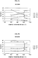
- test samples for each flange type were prepared. These test samples were heated for 30 minutes at firing temperatures shown in FIGS. 9A and 9B .
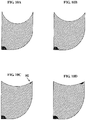
- FIGS. 10A to 10D The simulation results are shown in FIGS. 10A to 10D .
- the gray (shaded) part designates the zone of compressive stress (compressive residual stress); and the dark gray (fine meshed) part designates the zone of tensile stress (surface principle stress).
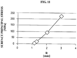
- the relationship between the tensile stress (surface principle stress) and the curvature radius R of the glass concave area is shown in FIG. 11 and TABLE 4.
- the surface principle stress (HS) refers to a tensile stress exerted on the vicinity of the surface of the outer circumferential surface of the glass material (e.g. the fine meshed part indicated by an arrow in FIG. 10C ).
- FIG. 10A corresponds to the case where: the curvature radius R was 1.2 mm; the width X of the glass accumulation region was 2.4 mm; and the height H5 of the glass material was 3 mm.
- FIG. 10B corresponds to the case where: the curvature radius R was 1.3 mm; the width X of the glass accumulation region was 2.4 mm; and the height H5 of the glass material was 3 mm.
- FIG. 10C corresponds to the case where: the curvature radius R was 2 mm; the width X of the glass accumulation region was 2.4 mm; and the height H5 of the glass material was 3 mm.
- FIG. 10D corresponds to the case where: the curvature radius R was 3 mm; the width X of the glass accumulation region was 2.4 mm; and the height H5 of the glass material was 3 mm.
- the average residual stress of the sample was 337 MPa.
- the average residual stress of the sample was 150 MPa in the case where the flange was of SUS 430. In either case, the residual stress was compressive stress.
- the present invention has been described with reference to the above specific embodiments, the present invention is not limited to those specific embodiments and can be embodied in various forms.
- the present invention is applicable to ceramic heaters for not only warm water washing toilet seat, but also fan heater, electric water heater, 24-hour bath etc., and manufacturing methods thereof.
Landscapes
- Chemical & Material Sciences (AREA)
- Engineering & Computer Science (AREA)
- Ceramic Engineering (AREA)
- Resistance Heating (AREA)
Applications Claiming Priority (2)
| Application Number | Priority Date | Filing Date | Title |
|---|---|---|---|
| JP2014223043 | 2014-10-31 | ||
| PCT/JP2015/080567 WO2016068242A1 (fr) | 2014-10-31 | 2015-10-29 | Élément chauffant en céramique et son procédé de fabrication |
Publications (3)
| Publication Number | Publication Date |
|---|---|
| EP3214896A1 true EP3214896A1 (fr) | 2017-09-06 |
| EP3214896A4 EP3214896A4 (fr) | 2018-07-04 |
| EP3214896B1 EP3214896B1 (fr) | 2020-09-02 |
Family
ID=55857577
Family Applications (1)
| Application Number | Title | Priority Date | Filing Date |
|---|---|---|---|
| EP15855716.5A Active EP3214896B1 (fr) | 2014-10-31 | 2015-10-29 | Élément chauffant en céramique et son procédé de fabrication |
Country Status (7)
| Country | Link |
|---|---|
| US (1) | US11096250B2 (fr) |
| EP (1) | EP3214896B1 (fr) |
| JP (1) | JP6174821B2 (fr) |
| KR (1) | KR101918427B1 (fr) |
| CN (1) | CN107113923B (fr) |
| ES (1) | ES2831361T3 (fr) |
| WO (1) | WO2016068242A1 (fr) |
Cited By (3)
| Publication number | Priority date | Publication date | Assignee | Title |
|---|---|---|---|---|
| WO2019171310A1 (fr) * | 2018-03-09 | 2019-09-12 | Formaster S.A. | Appareil de chauffage par écoulement servant à chauffer un fluide et/ou à générer de la vapeur, et ensemble appareil de chauffage et dispositif d'écoulement servant à chauffer un fluide et/ou à générer de la vapeur, comprenant ledit appareil de chauffage |
| EP3595406A1 (fr) * | 2018-07-12 | 2020-01-15 | Ngk Spark Plug Co., Ltd. | Dispositif de chauffage en céramique |
| CN111279791A (zh) * | 2017-10-31 | 2020-06-12 | 日本特殊陶业株式会社 | 流体加热用的陶瓷加热器 |
Families Citing this family (5)
| Publication number | Priority date | Publication date | Assignee | Title |
|---|---|---|---|---|
| DE102010042653A1 (de) | 2010-10-20 | 2012-04-26 | Robert Bosch Gmbh | Verfahren und Vorrichtung zur Objekterfassung |
| US12235018B2 (en) * | 2019-02-28 | 2025-02-25 | Kyocera Corporation | Heat exchanger and washing apparatus including heat exchanger |
| JP7249270B2 (ja) * | 2019-12-27 | 2023-03-30 | 日本特殊陶業株式会社 | セラミックヒータ |
| WO2021241276A1 (fr) * | 2020-05-25 | 2021-12-02 | 京セラ株式会社 | Dispositif de chauffage |
| WO2025243995A1 (fr) * | 2024-05-20 | 2025-11-27 | 京セラ株式会社 | Structure en céramique |
Family Cites Families (22)
| Publication number | Priority date | Publication date | Assignee | Title |
|---|---|---|---|---|
| US1425845A (en) * | 1922-02-23 | 1922-08-15 | Robert B Foster | Flange wrench |
| US2951929A (en) * | 1959-07-09 | 1960-09-06 | Westinghouse Electric Corp | Heating apparatus |
| US3284174A (en) * | 1962-04-16 | 1966-11-08 | Ind Fernand Courtoy Bureau Et | Composite structures made by bonding ceramics, cermets, alloys, heavy alloys and metals of different thermal expansion coefficient |
| US4149910A (en) * | 1975-05-27 | 1979-04-17 | Olin Corporation | Glass or ceramic-to-metal composites or seals involving iron base alloys |
| JPS57200261A (en) * | 1981-06-04 | 1982-12-08 | Matsushita Electric Industrial Co Ltd | Ceramic heating body |
| JPH01170846A (ja) * | 1987-12-26 | 1989-07-05 | Toyota Motor Corp | 限界電流検知式酸素濃度センサ |
| JP2557220Y2 (ja) * | 1991-03-26 | 1997-12-10 | 京セラ株式会社 | セラミックヒータ |
| DE4328718A1 (de) * | 1993-08-26 | 1995-03-02 | Abb Gadelius K K | Heizelement |
| JPH0669241U (ja) * | 1993-03-04 | 1994-09-27 | 日本特殊陶業株式会社 | セラミックフランジ構造体 |
| JP3285757B2 (ja) | 1996-04-17 | 2002-05-27 | 京セラ株式会社 | セラミック端子及びその製造方法 |
| JPH10220876A (ja) * | 1997-02-07 | 1998-08-21 | Matsushita Electric Ind Co Ltd | 温水装置 |
| JP3588233B2 (ja) | 1997-08-29 | 2004-11-10 | 京セラ株式会社 | セラミックヒータ |
| US7057140B2 (en) * | 2000-06-30 | 2006-06-06 | Balboa Instruments, Inc. | Water heater |
| US6574426B1 (en) * | 2002-11-18 | 2003-06-03 | Byron Blanco, Jr. | In-line tankless instantaneous electrical resistance water heater |
| JP2005183371A (ja) * | 2003-11-28 | 2005-07-07 | Ngk Spark Plug Co Ltd | セラミックヒータ、熱交換ユニット、温水洗浄便座、及びセラミックヒータの製造方法 |
| JP2006059794A (ja) * | 2004-07-20 | 2006-03-02 | Denso Corp | セラミックヒータ |
| JP2006120559A (ja) * | 2004-10-25 | 2006-05-11 | Ngk Spark Plug Co Ltd | セラミックヒータ、熱交換ユニット、及びセラミックヒータの製造方法 |
| US7875832B2 (en) * | 2004-12-20 | 2011-01-25 | Ngk Spark Plug Co., Ltd. | Ceramic heater, heat exchange unit, and warm water washing toilet seat |
| JP3940149B2 (ja) * | 2005-01-11 | 2007-07-04 | 京セラ株式会社 | 流体加熱装置 |
| US8294069B2 (en) * | 2007-03-28 | 2012-10-23 | Ngk Insulators, Ltd. | Heating device for heating a wafer |
| CN101456753A (zh) * | 2007-12-11 | 2009-06-17 | 曾松 | 陶瓷-不锈钢封接用玻璃焊料的制备方法 |
| CN203691661U (zh) * | 2013-12-24 | 2014-07-02 | 天万电热电器(中山)有限公司 | 一种防漏电的电热水设备用的电热管 |
-
2015
- 2015-10-29 US US15/519,586 patent/US11096250B2/en active Active
- 2015-10-29 JP JP2016556628A patent/JP6174821B2/ja active Active
- 2015-10-29 WO PCT/JP2015/080567 patent/WO2016068242A1/fr not_active Ceased
- 2015-10-29 EP EP15855716.5A patent/EP3214896B1/fr active Active
- 2015-10-29 CN CN201580058128.6A patent/CN107113923B/zh active Active
- 2015-10-29 KR KR1020177014204A patent/KR101918427B1/ko active Active
- 2015-10-29 ES ES15855716T patent/ES2831361T3/es active Active
Cited By (5)
| Publication number | Priority date | Publication date | Assignee | Title |
|---|---|---|---|---|
| CN111279791A (zh) * | 2017-10-31 | 2020-06-12 | 日本特殊陶业株式会社 | 流体加热用的陶瓷加热器 |
| KR20200081378A (ko) * | 2017-10-31 | 2020-07-07 | 니혼도꾸슈도교 가부시키가이샤 | 유체 가열용의 세라믹 히터 |
| EP3706508A4 (fr) * | 2017-10-31 | 2021-07-28 | NGK Spark Plug Co., Ltd. | Appareil de chauffage en céramique de chauffage de fluide |
| WO2019171310A1 (fr) * | 2018-03-09 | 2019-09-12 | Formaster S.A. | Appareil de chauffage par écoulement servant à chauffer un fluide et/ou à générer de la vapeur, et ensemble appareil de chauffage et dispositif d'écoulement servant à chauffer un fluide et/ou à générer de la vapeur, comprenant ledit appareil de chauffage |
| EP3595406A1 (fr) * | 2018-07-12 | 2020-01-15 | Ngk Spark Plug Co., Ltd. | Dispositif de chauffage en céramique |
Also Published As
| Publication number | Publication date |
|---|---|
| EP3214896A4 (fr) | 2018-07-04 |
| US11096250B2 (en) | 2021-08-17 |
| KR20170076753A (ko) | 2017-07-04 |
| CN107113923A (zh) | 2017-08-29 |
| WO2016068242A1 (fr) | 2016-05-06 |
| CN107113923B (zh) | 2021-04-09 |
| JPWO2016068242A1 (ja) | 2017-04-27 |
| US20170245324A1 (en) | 2017-08-24 |
| ES2831361T3 (es) | 2021-06-08 |
| JP6174821B2 (ja) | 2017-08-02 |
| KR101918427B1 (ko) | 2019-01-21 |
| EP3214896B1 (fr) | 2020-09-02 |
Similar Documents
| Publication | Publication Date | Title |
|---|---|---|
| EP3214896B1 (fr) | Élément chauffant en céramique et son procédé de fabrication | |
| US8193629B2 (en) | Bonding structure for a terminal of a susceptor of a semiconductor device manufacturing apparatus | |
| KR20150122699A (ko) | 저 열팽창 계수의 정상부를 갖는 받침부 구성 | |
| KR20090051703A (ko) | 면상 히터 | |
| EP3282814B1 (fr) | Appareil chauffant | |
| ES2891028T3 (es) | Manguito de calibración para un calibrador de bloque para calibrar un sensor de temperatura y calibrador de bloque con tal manguito de calibración | |
| US8414704B2 (en) | Bonding structure and semiconductor device manufacturing apparatus | |
| US6204486B1 (en) | Heater unit for semiconductor processing | |
| EP3101997B1 (fr) | Réchauffeur | |
| US9958340B2 (en) | Temperature sensor | |
| JP6502227B2 (ja) | セラミックヒータ | |
| EP2580582A1 (fr) | Porte-échantillons pour analyse thermique | |
| JP6526219B2 (ja) | 試料保持具 | |
| CN110719653B (zh) | 陶瓷加热器 | |
| CN115066408A (zh) | 接合体、保持装置以及静电卡盘 | |
| JP6502226B2 (ja) | セラミックヒータ | |
| US12451407B2 (en) | Composite material, semiconductor package, and method of manufacturing composite material | |
| US3665598A (en) | Method of making a heating body | |
| JP7671850B2 (ja) | 加熱装置 | |
| CN112798121B (zh) | 一种测温晶体测量气流温度的轴向安装方法 | |
| JPS6046791B2 (ja) | 核燃料模擬発熱体用シ−スヒ−タ | |
| KR20220113294A (ko) | 팽창/수축 디바이스를 이용하여 온도 검출기를 개선하기 위한 시스템 및 방법 | |
| JP7249270B2 (ja) | セラミックヒータ | |
| JP6957417B2 (ja) | ヒータ | |
| CN113251838A (zh) | 用于制造热管的方法 |
Legal Events
| Date | Code | Title | Description |
|---|---|---|---|
| STAA | Information on the status of an ep patent application or granted ep patent |
Free format text: STATUS: THE INTERNATIONAL PUBLICATION HAS BEEN MADE |
|
| PUAI | Public reference made under article 153(3) epc to a published international application that has entered the european phase |
Free format text: ORIGINAL CODE: 0009012 |
|
| STAA | Information on the status of an ep patent application or granted ep patent |
Free format text: STATUS: REQUEST FOR EXAMINATION WAS MADE |
|
| 17P | Request for examination filed |
Effective date: 20170413 |
|
| AK | Designated contracting states |
Kind code of ref document: A1 Designated state(s): AL AT BE BG CH CY CZ DE DK EE ES FI FR GB GR HR HU IE IS IT LI LT LU LV MC MK MT NL NO PL PT RO RS SE SI SK SM TR |
|
| AX | Request for extension of the european patent |
Extension state: BA ME |
|
| DAV | Request for validation of the european patent (deleted) | ||
| DAX | Request for extension of the european patent (deleted) | ||
| RIC1 | Information provided on ipc code assigned before grant |
Ipc: H05B 3/12 20060101ALI20180523BHEP Ipc: H05B 3/34 20060101ALI20180523BHEP Ipc: H05B 3/78 20060101ALI20180523BHEP Ipc: H05B 3/52 20060101ALI20180523BHEP Ipc: H05B 3/46 20060101ALI20180523BHEP Ipc: H05B 3/06 20060101AFI20180523BHEP |
|
| A4 | Supplementary search report drawn up and despatched |
Effective date: 20180601 |
|
| REG | Reference to a national code |
Ref country code: DE Ref legal event code: R079 Ref document number: 602015058579 Country of ref document: DE Free format text: PREVIOUS MAIN CLASS: H05B0003780000 Ipc: H05B0003060000 |
|
| GRAP | Despatch of communication of intention to grant a patent |
Free format text: ORIGINAL CODE: EPIDOSNIGR1 |
|
| STAA | Information on the status of an ep patent application or granted ep patent |
Free format text: STATUS: GRANT OF PATENT IS INTENDED |
|
| RIC1 | Information provided on ipc code assigned before grant |
Ipc: H05B 3/06 20060101AFI20200528BHEP Ipc: H05B 3/46 20060101ALI20200528BHEP Ipc: H05B 3/78 20060101ALI20200528BHEP Ipc: H05B 3/12 20060101ALI20200528BHEP Ipc: H05B 3/34 20060101ALI20200528BHEP Ipc: H05B 3/52 20060101ALI20200528BHEP |
|
| INTG | Intention to grant announced |
Effective date: 20200622 |
|
| GRAS | Grant fee paid |
Free format text: ORIGINAL CODE: EPIDOSNIGR3 |
|
| RAP1 | Party data changed (applicant data changed or rights of an application transferred) |
Owner name: NGK SPARK PLUG CO., LTD. |
|
| GRAA | (expected) grant |
Free format text: ORIGINAL CODE: 0009210 |
|
| STAA | Information on the status of an ep patent application or granted ep patent |
Free format text: STATUS: THE PATENT HAS BEEN GRANTED |
|
| AK | Designated contracting states |
Kind code of ref document: B1 Designated state(s): AL AT BE BG CH CY CZ DE DK EE ES FI FR GB GR HR HU IE IS IT LI LT LU LV MC MK MT NL NO PL PT RO RS SE SI SK SM TR |
|
| REG | Reference to a national code |
Ref country code: GB Ref legal event code: FG4D |
|
| REG | Reference to a national code |
Ref country code: AT Ref legal event code: REF Ref document number: 1310356 Country of ref document: AT Kind code of ref document: T Effective date: 20200915 Ref country code: CH Ref legal event code: EP |
|
| REG | Reference to a national code |
Ref country code: DE Ref legal event code: R096 Ref document number: 602015058579 Country of ref document: DE |
|
| REG | Reference to a national code |
Ref country code: IE Ref legal event code: FG4D |
|
| REG | Reference to a national code |
Ref country code: LT Ref legal event code: MG4D |
|
| PG25 | Lapsed in a contracting state [announced via postgrant information from national office to epo] |
Ref country code: NO Free format text: LAPSE BECAUSE OF FAILURE TO SUBMIT A TRANSLATION OF THE DESCRIPTION OR TO PAY THE FEE WITHIN THE PRESCRIBED TIME-LIMIT Effective date: 20201202 Ref country code: GR Free format text: LAPSE BECAUSE OF FAILURE TO SUBMIT A TRANSLATION OF THE DESCRIPTION OR TO PAY THE FEE WITHIN THE PRESCRIBED TIME-LIMIT Effective date: 20201203 Ref country code: BG Free format text: LAPSE BECAUSE OF FAILURE TO SUBMIT A TRANSLATION OF THE DESCRIPTION OR TO PAY THE FEE WITHIN THE PRESCRIBED TIME-LIMIT Effective date: 20201202 Ref country code: SE Free format text: LAPSE BECAUSE OF FAILURE TO SUBMIT A TRANSLATION OF THE DESCRIPTION OR TO PAY THE FEE WITHIN THE PRESCRIBED TIME-LIMIT Effective date: 20200902 Ref country code: HR Free format text: LAPSE BECAUSE OF FAILURE TO SUBMIT A TRANSLATION OF THE DESCRIPTION OR TO PAY THE FEE WITHIN THE PRESCRIBED TIME-LIMIT Effective date: 20200902 Ref country code: FI Free format text: LAPSE BECAUSE OF FAILURE TO SUBMIT A TRANSLATION OF THE DESCRIPTION OR TO PAY THE FEE WITHIN THE PRESCRIBED TIME-LIMIT Effective date: 20200902 Ref country code: LT Free format text: LAPSE BECAUSE OF FAILURE TO SUBMIT A TRANSLATION OF THE DESCRIPTION OR TO PAY THE FEE WITHIN THE PRESCRIBED TIME-LIMIT Effective date: 20200902 |
|
| REG | Reference to a national code |
Ref country code: NL Ref legal event code: MP Effective date: 20200902 |
|
| REG | Reference to a national code |
Ref country code: AT Ref legal event code: MK05 Ref document number: 1310356 Country of ref document: AT Kind code of ref document: T Effective date: 20200902 |
|
| PG25 | Lapsed in a contracting state [announced via postgrant information from national office to epo] |
Ref country code: LV Free format text: LAPSE BECAUSE OF FAILURE TO SUBMIT A TRANSLATION OF THE DESCRIPTION OR TO PAY THE FEE WITHIN THE PRESCRIBED TIME-LIMIT Effective date: 20200902 Ref country code: PL Free format text: LAPSE BECAUSE OF FAILURE TO SUBMIT A TRANSLATION OF THE DESCRIPTION OR TO PAY THE FEE WITHIN THE PRESCRIBED TIME-LIMIT Effective date: 20200902 Ref country code: RS Free format text: LAPSE BECAUSE OF FAILURE TO SUBMIT A TRANSLATION OF THE DESCRIPTION OR TO PAY THE FEE WITHIN THE PRESCRIBED TIME-LIMIT Effective date: 20200902 |
|
| PG25 | Lapsed in a contracting state [announced via postgrant information from national office to epo] |
Ref country code: EE Free format text: LAPSE BECAUSE OF FAILURE TO SUBMIT A TRANSLATION OF THE DESCRIPTION OR TO PAY THE FEE WITHIN THE PRESCRIBED TIME-LIMIT Effective date: 20200902 Ref country code: SM Free format text: LAPSE BECAUSE OF FAILURE TO SUBMIT A TRANSLATION OF THE DESCRIPTION OR TO PAY THE FEE WITHIN THE PRESCRIBED TIME-LIMIT Effective date: 20200902 Ref country code: RO Free format text: LAPSE BECAUSE OF FAILURE TO SUBMIT A TRANSLATION OF THE DESCRIPTION OR TO PAY THE FEE WITHIN THE PRESCRIBED TIME-LIMIT Effective date: 20200902 Ref country code: PT Free format text: LAPSE BECAUSE OF FAILURE TO SUBMIT A TRANSLATION OF THE DESCRIPTION OR TO PAY THE FEE WITHIN THE PRESCRIBED TIME-LIMIT Effective date: 20210104 Ref country code: CZ Free format text: LAPSE BECAUSE OF FAILURE TO SUBMIT A TRANSLATION OF THE DESCRIPTION OR TO PAY THE FEE WITHIN THE PRESCRIBED TIME-LIMIT Effective date: 20200902 |
|
| PG25 | Lapsed in a contracting state [announced via postgrant information from national office to epo] |
Ref country code: IS Free format text: LAPSE BECAUSE OF FAILURE TO SUBMIT A TRANSLATION OF THE DESCRIPTION OR TO PAY THE FEE WITHIN THE PRESCRIBED TIME-LIMIT Effective date: 20210102 Ref country code: AT Free format text: LAPSE BECAUSE OF FAILURE TO SUBMIT A TRANSLATION OF THE DESCRIPTION OR TO PAY THE FEE WITHIN THE PRESCRIBED TIME-LIMIT Effective date: 20200902 Ref country code: AL Free format text: LAPSE BECAUSE OF FAILURE TO SUBMIT A TRANSLATION OF THE DESCRIPTION OR TO PAY THE FEE WITHIN THE PRESCRIBED TIME-LIMIT Effective date: 20200902 |
|
| REG | Reference to a national code |
Ref country code: CH Ref legal event code: PL |
|
| REG | Reference to a national code |
Ref country code: DE Ref legal event code: R097 Ref document number: 602015058579 Country of ref document: DE |
|
| REG | Reference to a national code |
Ref country code: ES Ref legal event code: FG2A Ref document number: 2831361 Country of ref document: ES Kind code of ref document: T3 Effective date: 20210608 |
|
| PG25 | Lapsed in a contracting state [announced via postgrant information from national office to epo] |
Ref country code: SK Free format text: LAPSE BECAUSE OF FAILURE TO SUBMIT A TRANSLATION OF THE DESCRIPTION OR TO PAY THE FEE WITHIN THE PRESCRIBED TIME-LIMIT Effective date: 20200902 Ref country code: LU Free format text: LAPSE BECAUSE OF NON-PAYMENT OF DUE FEES Effective date: 20201029 Ref country code: MC Free format text: LAPSE BECAUSE OF FAILURE TO SUBMIT A TRANSLATION OF THE DESCRIPTION OR TO PAY THE FEE WITHIN THE PRESCRIBED TIME-LIMIT Effective date: 20200902 |
|
| PLBE | No opposition filed within time limit |
Free format text: ORIGINAL CODE: 0009261 |
|
| STAA | Information on the status of an ep patent application or granted ep patent |
Free format text: STATUS: NO OPPOSITION FILED WITHIN TIME LIMIT |
|
| REG | Reference to a national code |
Ref country code: BE Ref legal event code: MM Effective date: 20201031 |
|
| 26N | No opposition filed |
Effective date: 20210603 |
|
| GBPC | Gb: european patent ceased through non-payment of renewal fee |
Effective date: 20201202 |
|
| PG25 | Lapsed in a contracting state [announced via postgrant information from national office to epo] |
Ref country code: LI Free format text: LAPSE BECAUSE OF NON-PAYMENT OF DUE FEES Effective date: 20201031 Ref country code: SI Free format text: LAPSE BECAUSE OF FAILURE TO SUBMIT A TRANSLATION OF THE DESCRIPTION OR TO PAY THE FEE WITHIN THE PRESCRIBED TIME-LIMIT Effective date: 20200902 Ref country code: DK Free format text: LAPSE BECAUSE OF FAILURE TO SUBMIT A TRANSLATION OF THE DESCRIPTION OR TO PAY THE FEE WITHIN THE PRESCRIBED TIME-LIMIT Effective date: 20200902 Ref country code: CH Free format text: LAPSE BECAUSE OF NON-PAYMENT OF DUE FEES Effective date: 20201031 Ref country code: BE Free format text: LAPSE BECAUSE OF NON-PAYMENT OF DUE FEES Effective date: 20201031 |
|
| PG25 | Lapsed in a contracting state [announced via postgrant information from national office to epo] |
Ref country code: IE Free format text: LAPSE BECAUSE OF NON-PAYMENT OF DUE FEES Effective date: 20201029 |
|
| PG25 | Lapsed in a contracting state [announced via postgrant information from national office to epo] |
Ref country code: GB Free format text: LAPSE BECAUSE OF NON-PAYMENT OF DUE FEES Effective date: 20201202 |
|
| PG25 | Lapsed in a contracting state [announced via postgrant information from national office to epo] |
Ref country code: IS Free format text: LAPSE BECAUSE OF FAILURE TO SUBMIT A TRANSLATION OF THE DESCRIPTION OR TO PAY THE FEE WITHIN THE PRESCRIBED TIME-LIMIT Effective date: 20210102 Ref country code: TR Free format text: LAPSE BECAUSE OF FAILURE TO SUBMIT A TRANSLATION OF THE DESCRIPTION OR TO PAY THE FEE WITHIN THE PRESCRIBED TIME-LIMIT Effective date: 20200902 Ref country code: MT Free format text: LAPSE BECAUSE OF FAILURE TO SUBMIT A TRANSLATION OF THE DESCRIPTION OR TO PAY THE FEE WITHIN THE PRESCRIBED TIME-LIMIT Effective date: 20200902 Ref country code: CY Free format text: LAPSE BECAUSE OF FAILURE TO SUBMIT A TRANSLATION OF THE DESCRIPTION OR TO PAY THE FEE WITHIN THE PRESCRIBED TIME-LIMIT Effective date: 20200902 |
|
| PG25 | Lapsed in a contracting state [announced via postgrant information from national office to epo] |
Ref country code: MK Free format text: LAPSE BECAUSE OF FAILURE TO SUBMIT A TRANSLATION OF THE DESCRIPTION OR TO PAY THE FEE WITHIN THE PRESCRIBED TIME-LIMIT Effective date: 20200902 |
|
| P01 | Opt-out of the competence of the unified patent court (upc) registered |
Effective date: 20230512 |
|
| PG25 | Lapsed in a contracting state [announced via postgrant information from national office to epo] |
Ref country code: NL Free format text: LAPSE BECAUSE OF NON-PAYMENT OF DUE FEES Effective date: 20200923 |
|
| REG | Reference to a national code |
Ref country code: DE Ref legal event code: R081 Ref document number: 602015058579 Country of ref document: DE Owner name: NITERRA CO., LTD., NAGOYA-SHI, JP Free format text: FORMER OWNER: NGK SPARK PLUG CO., LTD., NAGOYA-SHI, AICHI, JP |
|
| REG | Reference to a national code |
Ref country code: ES Ref legal event code: PC2A Owner name: NITERRA CO., LTD. Effective date: 20240610 |
|
| PGFP | Annual fee paid to national office [announced via postgrant information from national office to epo] |
Ref country code: IT Payment date: 20250922 Year of fee payment: 11 |
|
| PGFP | Annual fee paid to national office [announced via postgrant information from national office to epo] |
Ref country code: FR Payment date: 20250908 Year of fee payment: 11 |
|
| PGFP | Annual fee paid to national office [announced via postgrant information from national office to epo] |
Ref country code: DE Payment date: 20250902 Year of fee payment: 11 |
|
| PGFP | Annual fee paid to national office [announced via postgrant information from national office to epo] |
Ref country code: ES Payment date: 20251103 Year of fee payment: 11 |