EP3215357B1 - Methode de fabrication de composants renforcés par fibres - Google Patents
Methode de fabrication de composants renforcés par fibres Download PDFInfo
- Publication number
- EP3215357B1 EP3215357B1 EP15794262.4A EP15794262A EP3215357B1 EP 3215357 B1 EP3215357 B1 EP 3215357B1 EP 15794262 A EP15794262 A EP 15794262A EP 3215357 B1 EP3215357 B1 EP 3215357B1
- Authority
- EP
- European Patent Office
- Prior art keywords
- mould
- cavity
- tub
- rigid
- pillar
- Prior art date
- Legal status (The legal status is an assumption and is not a legal conclusion. Google has not performed a legal analysis and makes no representation as to the accuracy of the status listed.)
- Active
Links
Images


Classifications
-
- B—PERFORMING OPERATIONS; TRANSPORTING
- B29—WORKING OF PLASTICS; WORKING OF SUBSTANCES IN A PLASTIC STATE IN GENERAL
- B29C—SHAPING OR JOINING OF PLASTICS; SHAPING OF MATERIAL IN A PLASTIC STATE, NOT OTHERWISE PROVIDED FOR; AFTER-TREATMENT OF THE SHAPED PRODUCTS, e.g. REPAIRING
- B29C70/00—Shaping composites, i.e. plastics material comprising reinforcements, fillers or preformed parts, e.g. inserts
- B29C70/68—Shaping composites, i.e. plastics material comprising reinforcements, fillers or preformed parts, e.g. inserts by incorporating or moulding on preformed parts, e.g. inserts or layers, e.g. foam blocks
- B29C70/86—Incorporated in coherent impregnated reinforcing layers, e.g. by winding
-
- B—PERFORMING OPERATIONS; TRANSPORTING
- B29—WORKING OF PLASTICS; WORKING OF SUBSTANCES IN A PLASTIC STATE IN GENERAL
- B29C—SHAPING OR JOINING OF PLASTICS; SHAPING OF MATERIAL IN A PLASTIC STATE, NOT OTHERWISE PROVIDED FOR; AFTER-TREATMENT OF THE SHAPED PRODUCTS, e.g. REPAIRING
- B29C43/00—Compression moulding, i.e. applying external pressure to flow the moulding material; Apparatus therefor
- B29C43/02—Compression moulding, i.e. applying external pressure to flow the moulding material; Apparatus therefor of articles of definite length, i.e. discrete articles
- B29C43/18—Compression moulding, i.e. applying external pressure to flow the moulding material; Apparatus therefor of articles of definite length, i.e. discrete articles incorporating preformed parts or layers, e.g. compression moulding around inserts or for coating articles
-
- B—PERFORMING OPERATIONS; TRANSPORTING
- B29—WORKING OF PLASTICS; WORKING OF SUBSTANCES IN A PLASTIC STATE IN GENERAL
- B29C—SHAPING OR JOINING OF PLASTICS; SHAPING OF MATERIAL IN A PLASTIC STATE, NOT OTHERWISE PROVIDED FOR; AFTER-TREATMENT OF THE SHAPED PRODUCTS, e.g. REPAIRING
- B29C45/00—Injection moulding, i.e. forcing the required volume of moulding material through a nozzle into a closed mould; Apparatus therefor
- B29C45/14—Injection moulding, i.e. forcing the required volume of moulding material through a nozzle into a closed mould; Apparatus therefor incorporating preformed parts or layers, e.g. injection moulding around inserts or for coating articles
- B29C45/14336—Coating a portion of the article, e.g. the edge of the article
- B29C45/14418—Sealing means between mould and article
-
- B—PERFORMING OPERATIONS; TRANSPORTING
- B29—WORKING OF PLASTICS; WORKING OF SUBSTANCES IN A PLASTIC STATE IN GENERAL
- B29C—SHAPING OR JOINING OF PLASTICS; SHAPING OF MATERIAL IN A PLASTIC STATE, NOT OTHERWISE PROVIDED FOR; AFTER-TREATMENT OF THE SHAPED PRODUCTS, e.g. REPAIRING
- B29C45/00—Injection moulding, i.e. forcing the required volume of moulding material through a nozzle into a closed mould; Apparatus therefor
- B29C45/14—Injection moulding, i.e. forcing the required volume of moulding material through a nozzle into a closed mould; Apparatus therefor incorporating preformed parts or layers, e.g. injection moulding around inserts or for coating articles
- B29C45/14778—Injection moulding, i.e. forcing the required volume of moulding material through a nozzle into a closed mould; Apparatus therefor incorporating preformed parts or layers, e.g. injection moulding around inserts or for coating articles the article consisting of a material with particular properties, e.g. porous, brittle
- B29C45/14786—Fibrous material or fibre containing material, e.g. fibre mats or fibre reinforced material
-
- B—PERFORMING OPERATIONS; TRANSPORTING
- B29—WORKING OF PLASTICS; WORKING OF SUBSTANCES IN A PLASTIC STATE IN GENERAL
- B29C—SHAPING OR JOINING OF PLASTICS; SHAPING OF MATERIAL IN A PLASTIC STATE, NOT OTHERWISE PROVIDED FOR; AFTER-TREATMENT OF THE SHAPED PRODUCTS, e.g. REPAIRING
- B29C70/00—Shaping composites, i.e. plastics material comprising reinforcements, fillers or preformed parts, e.g. inserts
- B29C70/04—Shaping composites, i.e. plastics material comprising reinforcements, fillers or preformed parts, e.g. inserts comprising reinforcements only, e.g. self-reinforcing plastics
- B29C70/06—Fibrous reinforcements only
- B29C70/08—Fibrous reinforcements only comprising combinations of different forms of fibrous reinforcements incorporated in matrix material, forming one or more layers, and with or without non-reinforced layers
- B29C70/081—Combinations of fibres of continuous or substantial length and short fibres
-
- B—PERFORMING OPERATIONS; TRANSPORTING
- B29—WORKING OF PLASTICS; WORKING OF SUBSTANCES IN A PLASTIC STATE IN GENERAL
- B29C—SHAPING OR JOINING OF PLASTICS; SHAPING OF MATERIAL IN A PLASTIC STATE, NOT OTHERWISE PROVIDED FOR; AFTER-TREATMENT OF THE SHAPED PRODUCTS, e.g. REPAIRING
- B29C70/00—Shaping composites, i.e. plastics material comprising reinforcements, fillers or preformed parts, e.g. inserts
- B29C70/04—Shaping composites, i.e. plastics material comprising reinforcements, fillers or preformed parts, e.g. inserts comprising reinforcements only, e.g. self-reinforcing plastics
- B29C70/06—Fibrous reinforcements only
- B29C70/10—Fibrous reinforcements only characterised by the structure of fibrous reinforcements, e.g. hollow fibres
- B29C70/12—Fibrous reinforcements only characterised by the structure of fibrous reinforcements, e.g. hollow fibres using fibres of short length, e.g. in the form of a mat
-
- B—PERFORMING OPERATIONS; TRANSPORTING
- B29—WORKING OF PLASTICS; WORKING OF SUBSTANCES IN A PLASTIC STATE IN GENERAL
- B29C—SHAPING OR JOINING OF PLASTICS; SHAPING OF MATERIAL IN A PLASTIC STATE, NOT OTHERWISE PROVIDED FOR; AFTER-TREATMENT OF THE SHAPED PRODUCTS, e.g. REPAIRING
- B29C70/00—Shaping composites, i.e. plastics material comprising reinforcements, fillers or preformed parts, e.g. inserts
- B29C70/68—Shaping composites, i.e. plastics material comprising reinforcements, fillers or preformed parts, e.g. inserts by incorporating or moulding on preformed parts, e.g. inserts or layers, e.g. foam blocks
- B29C70/74—Moulding material on a relatively small portion of the preformed part, e.g. outsert moulding
- B29C70/76—Moulding on edges or extremities of the preformed part
-
- B—PERFORMING OPERATIONS; TRANSPORTING
- B62—LAND VEHICLES FOR TRAVELLING OTHERWISE THAN ON RAILS
- B62D—MOTOR VEHICLES; TRAILERS
- B62D29/00—Superstructures, understructures, or sub-units thereof, characterised by the material thereof
- B62D29/04—Superstructures, understructures, or sub-units thereof, characterised by the material thereof predominantly of synthetic material
- B62D29/046—Combined superstructure and frame, i.e. monocoque constructions
Definitions
- This invention relates to fibre-reinforced components and methods of manufacturing such components.
- FRC fibre-reinforced composite
- Such materials typically comprise a matrix that contains reinforcing fibres.
- the matrix could be an epoxy resin and the fibres could be carbon fibre (CF) strands.
- CFRP carbon fibre
- Materials of this type can have good strength in comparison to their weight.
- the processes required to make components from fibre-reinforced materials can be complex.
- RTM resin transfer moulding
- the reinforcing fibres are laid up in a mould cavity, liquid resin is injected into the mould cavity and the resin is cured, typically by heating the mould body. Once the resin has become solid the mould can be opened and the resulting component removed.
- the resin can be injected by drawing a vacuum in the mould cavity and allowing the vacuum to pull the resin into the mould.
- the mould cavity can be defined by rigid mould tools, which has the advantage of giving good control over the dimensional accuracy and surface finish of the component.
- long fibre runs, and woven mats of fibres can be embedded in the matrix, giving the end component great strength.
- RTM can be used for major structural components, such as vehicle tubs, as described in EP 2 772 416 .
- One disadvantage of RTM is that it is difficult to achieve complex shape detail with a good degree of strength in the moulded component because it is difficult to lay up long reinforcing fibres in complex or confined regions of the mould.
- Another process for forming FRC components is to form a precursor which comprises a liquid resin mixed with short reinforcing fibres.
- the short fibres could be, for example, around 25mm long.
- Such precursors are sometimes known as sheet moulding compound (SMC).
- SMC sheet moulding compound
- the precursor is then injected into a mould cavity and the resin is cured to form a solid matrix which encapsulates the short fibres.
- the resulting component can then be removed from the mould.
- This flow moulding process is often used to form sheet parts of complex shapes. In comparison to the RTM process, the flow moulding process allows reinforcing fibres to be readily incorporated even into intricate regions of a moulded component. However, the strength of flow moulded components is considerably less than can be achieved with RTM components.
- the tensile strength and modulus of an RTM component could be around 1000MPa and 100GPa respectively, whereas the corresponding values for a flow moulded component could be 200MPa and 30GPa.
- RTM vehicle-to-vehicle
- flow moulding is less desirable for producing major structural vehicle components such as tubs, engine supports or crash protection structures.
- the flow moulded component would be much heavier than an analogous RTM component.
- forming such components using flow moulding would have the advantage that detailed structural elements could be formed integrally with the component rather than attached as a separate manufacturing stage.
- a typical RTM vehicle tub is generally made up of a structure of flat-sided interconnected beams. To form a vehicle around such a structure requires attaching additional parts to the tub.
- Such parts might include a projecting rib onto which a door seal can be clipped, or a shaped flange surrounding a windscreen opening onto which a sheet of windscreen glass can be adhered. Conventionally those parts are manufactured and then glued or bolted to the tub.
- thermoplastic carbon-fibre-reinforced part manufactured from a composite sheet can have ribbing moulded onto it in the injection moulding process, along with other integration and function elements.
- a continuous-fibre reinforced sheet blank can be impregnated with a matrix precursor and then thermoformed in a mould. Then further matrix material can be injected into parts of a mould volume to form additional features.
- an element made of a carbon fibre prepreg can be shaped and then positioned next to a carbon fibre SMC body in a mould.
- the mould can be closed to form the SMC blank to shape and press it against a sheet part of the prepreg body, and the prepreg and the SMC body can be cured. (See “ Development of PCM Technology", Koichi Akiyama, SPE ACCE 2011 ).
- WO 99/52703 and WO 2004/024424 describe structural components consisting of fibre-reinforced thermoplastic plastic and their method of production.
- the components has a long fibre-reinforced thermoplastic matrix and continuous fibre strands.
- the step of locating comprises closing the mould against the rigid element without substantially altering the shape of the rigid element.
- the closed mould may surround part or all of the rigid element.
- the rigid element may be hollow in the region adjacent the cavity.
- the exterior of the rigid element may be defined by sheet structures in the region adjacent the cavity.
- the thickness of the sheet structures may be less than 10mm, less than 7mm or less than 5mm.
- the method may comprise, prior to the loading step, heating the mould to a temperature at which the matrix of the rigid element will soften.
- the temperature to which the mould is heated may be between the glass transition temperature of the matrix of the rigid element and 20°C above that temperature.
- the step of closing the mould may comprise indenting the mould into the surface of the rigid element so as to seal the cavity.
- the mould may comprise a first part of the mould and a second part of the mould, the first part of the mould may comprise a mould body and at least one mould slider moveable between an extended position and a retracted position relative to the mould body, and the step of locating may comprise closing the mould against the rigid element by: bringing the at least one mould slider, in the extended position, into contact with a second part of the mould, closing the first part of the mould and the second part of the mould around the rigid composite element so that the mould slider moves between the extended position and the retracted position.
- the step of bringing the at least one mould slider into contact with a second part of the mould may comprise securing the rigid composite element in the second part of the mould by the at least one mould slider.
- the rigid composite element comprises at least one projection
- the mould is shaped to fit against the contours of the surfaces of the projection facing away from the cavity
- the step of locating comprises locating at least one projection at an edge the cavity.
- the projection may extend away from the exterior surface of the rigid composite element.
- the method may comprise heating the said material to a temperature at which the matrix of the rigid element will soften.
- the temperature to which the said material is heated may be between the glass transition temperature of the matrix of the rigid element and 20°C above that temperature.
- the method comprises heating the said material to the said temperature after or before loading it into the cavity.
- the method may comprise the step of forming the rigid composite element by resin transfer moulding.
- the rigid composite element may be a tub for a vehicle.
- the cavity may be adjacent to a portion of the tub forming part of a crash structure.
- the cavity may, for example be adjacent to an A-pillar, B-pillar, C-pillar, cross-beam or sill of the tub.
- the material injected into the cavity may define a feature running lengthwise along such an element.
- the material injected into the cavity may define a structural feature of the crash structure.
- the feature may be one of a flange for carrying a door seal and a flange for bonding glass to.
- the method may comprise, prior to the step of loading, coating at least a part of the surface of the rigid element with an adhesive, that part of the surface being overlain by the cavity.
- the adhesive may be applied as a peelable film.
- a rigid vehicle tub is formed as a long-fibre composite element, for example by resin transfer moulding. Then the tub is transferred to another mould which accommodates all or part of the tub and defines one or more mould cavities adjacent to the outer surface of the tub. That second mould is shaped so as to conform to the exterior contours of part or all of the tub. That mould is sealed against the outer surface of the tub 11, and then a material comprising a fluid matrix precursor in which short reinforcing fibres have been dispersed loaded into the mould cavities. The matrix precursor is cured, leaving the material in the cavities adhered to the tub as overmoulded elements. The overmoulded elements could contribute substantially to the structural strength of the tub. Similar principles could be adopted for parts other than vehicle tubs.
- Figure 1 shows a carbon fibre reinforced vehicle tub frame 1 formed by resin transfer moulding.
- the tub frame comprises side sills 2 which run along the sides of the tub.
- a floor 3 extends between the sills.
- A-pillars 4 rise from the sills.
- the upper ends of the A-pillars are joined by a cross-member 5.
- C-pillars 6 rise from the sills.
- the C-pillars are joined by a cross-member 7.
- the sills, pillars and cross-members are formed as hollow tubes. This can be achieved by inflating a bladder within each tube during the RTM process.
- the RTM process involves laying up long fibre reinforcement in a mould, injecting a matrix precursor into the mould, curing the matrix precursor to form a rigid matrix around the reinforcing fibres and removing the resulting component from the mould.
- the RTM mould defines the exterior shape of the RTM component.
- the walls forming the tub frame are formed of rigid, cured epoxy in which are embedded long runs of carbon fibre.
- the fibre could be in the form of tow, mats or individual fibres.
- the mean length of the fibres in the walls could be greater than 10cm or 50cm.
- the fibres are laid up in a way that strengthens the tub frame against the stresses expected to be imposed on it in use. Typically most parts of the walls will contain multiple layers of reinforcing fibre.
- the fibres may run generally longitudinally and/or generally circumferentially. Fibres running generally circumferentially are known as hoop fibres.
- Figure 2 shows a cut-away view of an A-pillar 4 of the tub frame.
- the A-pillar is in the form of a tube having an outer surface 10 and a hollow interior 11.
- the wall of the tube is formed of a matrix material indicated at 12.
- Longitudinal fibres are indicated at 13, and hoop fibres are indicated at 14. The longitudinal fibres and the hoop fibres could overlap.
- the tub frame as shown in figures 1 and 2 is convenient for manufacture as a high strength element by RTM because it does not have any detailed surface features. As a result, when the carbon fibres are being laid up in the mould in preparation for injection of the resin, it is relatively easy to arrange that long carbon fibres can be included substantially throughout the structure of the tub frame.
- the tub frame is preferably formed by RTM: that is by the positioning of reinforcing fibres in a mould, followed by the injection of liquid resin into the mould, followed by the curing of the resin to rigidity the moulded component.
- a vacuum may be drawn in the mould before the resin is injected, and the vacuum may then pull the resin into the mould.
- the mould may be heated to promote curing of the resin.
- Alternative methods may be used to form the tub frame. For example it could be formed by laying up mats of reinforcing fibre that have been pre-impregnated with resin (prepreg) and then curing the resin.
- Figure 3 shows stages in the subsequent processing of the tub frame to form a final tub for a vehicle.
- Figure 3a is a cross-section through the A-pillar 4 of the tub frame, after it has been formed and cured.
- FIG. 3b illustrates a cross-section through the A-pillar and the mould once the tub frame has been inserted in the mould.
- the A-pillar is shown at 20.
- the mould is composed of a first mould body 21 and a second mould body 22, which abut each other and define the mould cavity between them.
- the entire mould could be composed of several such mould bodies, which can be assembled to form the mould and disassembled to allow the tub frame to be placed in and released from the mould.
- the mould encircles the A-pillar. In some places the surface of the mould cavity defined by the mould bodies lies adjacent to the exterior surface of the tub frame, as indicated at 23. In other places the surface of the mould cavity defines a free volume between that surface and the exterior surface of the tub frame, as indicated at 24, 25, 26.
- the tub Prior to being contacted with the SMC material the tub is fully cured and rigid.
- the SMC material may be in the form of a semi-rigid body comprising resin and short fibres. That body can be loaded together with the tub frame into the mould cavity. Then the mould can be closed. In this approach the closing of the mould shapes the SMC body to the mould cavity and forces the SMC body into intimate contact with the adjacent surfaces of the tub frame. The pressure exerted as the mould closes causes the SMC body to flow plastically so as to fill the volumes 24, 25, 26 between the exterior surface of the tub frame and the surface of the mould cavity. In this approach the ports 27 can be omitted, or can be used to draw a vacuum in the mould cavity after the mould is closed.
- the SMC material may initially be in a liquid form comprising a mixture of liquid resin and short fibres. Once the mould is closed with the tub in place within it the liquid SMC material can be loaded into the mould be injecting it through multiple ports 27 extending from the exterior of the mould bodies to the volumes 24, 25, 26. Before the SMC material is injected the mould cavity may be evacuated so as to reduce the chance of air being trapped in the mould when the SMC materials is injected.
- Figure 4 shows a configuration of the mould bodies and one set of steps of closing the mould bodies around the A-pillar 20.
- At least one of the mould bodies 22 may comprise a main mould body 69 and at least one movable member 70, 71.
- the movable member 70, 71 may be capable of sliding relative to the main mould body 69.
- the sliding of movable member 70, 71 may be undertaken by one or more actuators (not shown) that may form part of the general moulding apparatus used to control the moulding process.
- the moveable members maybe be capable of sliding relative to the main mould body 69 between an extended position (as shown in figure 4b ) and a retracted position (as shown in figure 4a ).
- the moveable members may be referred to as mould sliders 70, 71.
- the mould bodies may be referred to as a tool part and so the moveable members may be referred to as tool sliders 70, 71.
- the position within the mould body 22 of the or each moveable member 70, 71 may be selected so that the moveable member(s) engage with the A-pillar 20 prior to the closing of the main mould body 69 against the other mould bodies that surround the A-pillar 20.
- the moveable member(s) 70, 71 secure the A-pillar within the first mould body 21 prior to the closure of the main mould body 69 of second mould body 22 against the first mould body 21.
- the securing of the A-pillar may prevent any SMC material from flowing around the A-pillar 20 prior to the closure of the main mould body 69.
- first mould body 21 closes against second mould body 22.
- moveable members are received in openings 72, 73 within the main mould body as the second mould body 22.
- the openings 72, 73 are configured to receive moveable member(s) 70, 71 as the moveable members slide between the extended position and the retracted position relative to the main mould body 69.
- the volumes are not shown in Figure 4c for clarity but also because they may not be present in another part of the mould.
- Figure 5 shows a close-up view of part of the cross-section through the A-pillar and the mould once the tub frame has been inserted in the mould.
- the A-pillar is shown at 20.
- Only part of the first mould body 21 is shown in Figure 5 , but it will be appreciated that the following description could equally be applied to the rest of the first mould body 21 not shown in figure 5 .
- the surface of the mould cavity defines a free volume between that surface and the exterior surface of the tub frame as indicated at 25 in Figure 5 and at 24, 25, 26 in Figure 3b .
- the exterior surface of the tub frame comprises one or more projections 60, 61 extending away from the exterior surface of the tub frame. These projections 60, 61 have been formed during the moulding process of the tub frame.
- the projections may comprise both resin and reinforcing fibres, or may only be composed of resin.
- the projections are configured to act as a barrier to the flow of the SMC material. In this way, the SMC material can be contained within the region of the exterior surface of the tub frame delimited by the one or more projections.
- a projection may be located at the edge of a free volume defined between the surface of the mould cavity and the exterior surface of the tub frame.
- a projection may be located where the surface of the mould cavity starts being in an adjacent position to the exterior surface of the tub frame.
- the projection assists in defining the outer edge of a region of SMC material that is to be cured to the exterior surface of the tub frame.
- the projection may be present along the whole edge of the free volume or it may be present along only part of the edge of the free volume.
- the length and configuration of the projection may be selected depending on the profile of the exterior surface of the tub frame and thus the likelihood of leakage of SMC material from a particular free volume.
- Each projection may form a resin barrier to restrict the flow of SMC material.
- the mould body may be shaped so as to comprise complimentary regions in the surface of the mould cavity that lie adjacent the exterior surface of the projections. In this way, the complimentary regions in the surface of the mould cavity can seal against the exterior surface of the projections to limit or prevent flow of SMC material out of the free volume.
- the mould body surface, in the complimentary regions, and the surface of the projections may be controlled to tight tolerances so as to ensure the necessary engagement between the mould body and the exterior surface of the tub frame is achieved to prevent overspill of SMC material.
- FIG. 3c shows the situation after the SMC material has been cured and the resulting component has been removed from the mould.
- the free volumes 24, 25, 26 have been filled with SMC material as shown at 24', 25', 26' which is now integral with the material of the tub frame 20.
- the SMC material is a liquid matrix precursor (e.g. curable resin) which contains a multiplicity of short reinforcing fibres.
- the fibres are preferably distributed substantially uniformly in the liquid precursor.
- the fibres may be orientated randomly, or there may be preferential orientation of the fibres due, for example, to the flow behaviour of the liquid precursor when it is compressed by the closing of the mould or is injected into the mould.
- the proportion of fibres contained in the SMC material will depend on the properties of the materials and the desired application, but it could be between 40% and 60% in volume fraction.
- the mean length of the short fibres is preferably in the range from 10mm to 60mm.
- the liquid matrix precursor could be a resin, for example an epoxy, nylon, polyester resin or vinyl ester resin.
- the fibres could be fibres of a material having higher tensile strength than the cured matrix material.
- the fibres could, for example, be carbon fibre, glass fibre or fibres of a polymer such as an aramid.
- the mould is heated to cause the matrix precursor to cure and solidify, e.g. by cross-linking. Then the mould is opened and the solid moulded final tub is removed.
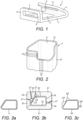
- Figure 6 illustrates some examples of the structures that can be overmoulded onto the pre-cured tub frame in this way.
- Figure 6 shows a cut-away partial view of an A-pillar for an automobile.
- a part of an initially formed tub frame, for example made by RTM, is indicated at 30.
- Additional elements 31, 32, 33 are formed from SMC material overmoulded on to the initially formed tub part.
- the elements 31 and 32 together with the tub frame define a seat for windscreen glass.
- Element 33 is a rib that protrudes from the initially moulded tub frame. The rib can serve as an attachment for a rubber door sealing strip which can clip around the rib.
- SMC overmoulding steps include attachment pads or brackets for components such as hinges; housings for components such as mirrors, lights or cameras; lugs or sockets to which other parts can be clipped; and other functional or cosmetic detail parts.
- attachment pads or brackets for components such as hinges
- housings for components such as mirrors, lights or cameras
- lugs or sockets to which other parts can be clipped and other functional or cosmetic detail parts.
- One advantage of the process described above is that the relatively expensive RTM process can be used for making the key load-bearing parts of the final component, but the detailed parts of the same component can be made by flow moulding.
- Elements such as flanges 31, 32 and rib 33 could alternatively be manufactured separately from the tub frame and then attached to the tub frame with adhesive or with screws or bolts.
- a much greater degree of adhesion can be achieved between the additional elements and the tub frame.
- the overmoulded elements can contribute significantly to the strength of the final tub.
- calculations for operational or crash loads on structural elements of the tub, including crash structures can take into account the contribution to strength provided by the overmoulded elements.
- the overmoulded elements can be structural parts of the vehicle, contributing substantially to the strength of the final tub.
- crash protection structures include forward and rear beams extending from a passenger cell to forward and rear bumpers respectively, side beams for resisting sideways ingress into a passenger cell and roll-over protection systems such as A-pillars and roll-over hoops or struts.
- overmoulded elements illustrated in figure 6 run along the longitudinal extent of the A-pillar. In that way they can help to contribute to the bending strength of the A-pillar.
- the adhesion of the overmoulded elements to the tub frame can be enhanced if the matrix of the overmoulded elements is of the same or substantially the same material as the matrix of the matrix of the tub frame.
- the matrix of the overmoulded elements could both be of the same structural polymer or of polymers having substantially the same coefficient of thermal expansion once cured.
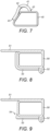
- Figure 7 shows an alternative arrangement for overmoulding on to the previously rigidified tub frame 40.
- the mould 41 that defines the mould cavity 42 for the overmoulding process does not encircle the tub. Instead the rim 43 of the mould cavity abuts the tub.
- the mould and the tub, or part of it can be surrounded by a vacuum bag and a vacuum drawn therein during the step of loading the overmould material, closing the mould and/or injecting the overmould material.
- the SMC material is moulded against the exterior surface of a region of the tub frame that is hollow. That means that the material of the tub against which the SMC material exerts pressure (e.g. when it is shaped during closing of the mould) has a void on its opposite face to the SMC material. The mould does not directly press against that opposite face because it is enclosed by the tub body. When the mould is not present directly behind the part of the tub body on which the SMC material is pressing there is a risk that the tub body will flex during the moulding process. This raises a number of difficulties. First, it is more difficult to achieve a seal between the mould and the tub structure to prevent the SMC material from spreading outside the mould. Second, it is possible that the tub structure might be permanently deformed, either through overloading or because the SMC material sets with the hollow tub part in a deformed condition.
- the performance of the final tub structure is improved if the mould 21, 22, 41 used to form the SMC structure is heated to a temperature at which the matrix material of the tub frame will soften. That temperature will depend on the nature of the matrix material, but it may be above the glass transition temperature (T g ) of the matrix material.
- T g glass transition temperature
- the temperature to which the mould body/bodies is /are heated is preferably not more than 10°C or 20°C above T g of the matrix material.
- the SMC material may be heated to such a temperature during the process of curing it. It is believed that elevating the temperature of the mould and/or the SMC material in this way can help to relieve stress in the tub frame that could otherwise arise from the overmoulding of the SMC material.
- the rim 43 when the rim of the mould cavity abuts the tub frame as shown in figure 7 , in order for the mould cavity to be fully closed and thereby prevent leakage of SMC material from the mould cavity when it is compressed, the rim 43 must seal against the surface of the previously rigidified tub. This sealing can be assisted by heating the mould 41 to a temperature at which the matrix material of the tub 40 will soften. Then the mould can be pressed somewhat into the tub, conforming the tub to the rim 43 of the mould 41 and permitting a better seal between the two. A good seal is particularly significant since the SMC material has relatively low viscosity, especially at elevated temperatures.
- Sealing of the mould 41 against the tub frame 40 can also be enhanced by providing significant hoop fibres in the tub frame at the region where the mould 41 is to seal against it.
- those sections of reinforcing fibre that are orientated at 45° or more to the principal longitudinal axis of the hollow part of the tub that is being overmoulded may constitute more than 10% or more than 15% or more than 20% of the total length of reinforcing fibres in that hollow part of the tub.
- Those sections of reinforcing fibre that are orientated at 45° or less to a plane transverse to the extent of the cavity running along the hollow part of the tub that is being overmoulded may constitute more than 10% or more than 15% or more than 20% of the total length of reinforcing fibres in that hollow part of the tub. It has been found that when the mould cavity is closed so as to deform the already-loaded SMC material, or SMC material is injected into the mould cavity, there can be a tendency for the tub frame member, being hollow, to deform inwards. That deformation can break the seal of the mould against the tub frame member, allowing SMC material to leak from the mould cavity.
- the tub frame can be strengthened against that deformation by means of hoop fibres in the region where the mould 41 is to be applied.
- SMC compounds contain a release agent to help the cured SMC component to be released from a mould. If such SMC compounds are used to overmould the tub frame then it can be advantageous to take additional steps to improve adhesion between the SMC overmould and the tub frame.
- One way to achieve that is to coat the tub frame with adhesive in the region where the SMC component is to be overmoulded before the tub frame is located in or against the mould for the SMC component.
- the adhesive could be applied as a liquid to the appropriate region. More conveniently it could be applied as a sheet. For example, the adhesive could initially be provided on a backing sheet which is coated with a release layer and an adhesive layer over the release layer. Then the adhesive side of the sheet can be located against the appropriate region and the backing sheet removed, leaving the adhesive stuck to the tub frame.
- any suitable material could be used for the matrix material of each of the initially formed element and the matrix material of the overmoulded element.
- Each matrix material could be a polymer, for example, an epoxy, a nylon, a polyester or a vinyl ester.
- the matrix materials could be different or the same.
- the matrix material of the initially formed element is capable of softening to a limited extent at a temperature suitable for curing the matrix material of the overmoulded element.
- a suitable temperature for curing the matrix material of the overmoulded element may be in the range from the T g of the matrix material to 10°C or 20°C above that T g .
- any suitable material could be used for the reinforcing fibres of each of the initially formed element and the reinforcing fibres of the overmoulded element.
- Each fibre material could, for example, be carbon fibre, glass fibre or a polymer fibre such as an aramid fibre.
- the fibre materials could be different or the same.
- the initially formed element can be a continuous fibre element. That is, it can be formed of fibres having a length greater than 10cm, or greater than 20cm, or greater than 30cm, or greater than 50cm, or greater than 1m.
- the initially formed element is a vehicle tub.
- the initially formed element could be for any appropriate purpose: for example it could be a vehicle seat, a bicycle frame, a vehicle suspension element or a casing for a mobile phone. More than one initially formed element could be inserted into the mould for the overmoulding process, and they could be joined together by the overmould.
- the initially formed element could be formed by RTM or by any other suitable process.
- FIG. 8 shows a plan cross-section of such an A-pillar in a vehicle.
- the structural wall of the A-pillar is shown at 50.
- a glass windscreen 51 is adhered to the front surface of the A-pillar.
- a weather strip or interior trim seal 52 seals the A-pillar against the door of the vehicle when the door (not shown) is closed.
- the rear-facing and interior side surfaces of the A-pillar are covered with a cosmetic and cushioning cover layer 53.
- Figure 9 shows an alternative design of A-pillar, in which like parts are indicated as for figure 8 .
- the majority of the interior side surface of the A-pillar is not covered by the cover layer 53.
- the cover layer extends over the rearward-facing part of the A-pillar but stops at or near the transition to the sideways-facing interior surface of the A-pillar, as indicated at 54.
- the cover layer may cover extend only over the rearward-facing part of the A-pillar, or it may extend a little on to the lateral surface, as shown in figure 9 . It is preferred that the majority of the side surface of the structural element of the A-pillar, most preferably at least the forward 50% of the structural element of the A-pillar is free from covering. It is preferred that over the height of the A-pillar all or the majority of the regions of the sideways-facing interior surface of the A-pillar nearest to the windscreen are free from the cover layer. For example, considering the portions of that surface that constitute the nearest 25% or nearest 10% of that surface to the windscreen, preferably all or the majority or more than 75% or more than 90% of those portions are free from the cover layer.
- the interior sideways-facing surface of the A-pillar is entirely free from the cover layer along its edge bordering the windscreen over either the upper 50% of the A-pillar or the upper 80% of the A-pillar or over the whole of the length of the A-pillar.
- the covering could be a cushioning covering such as a foam or rubber and/or a cosmetic covering such as a cloth or leather.
- the exposed side surface of the A-pillar may have an integral coating such as a varnish or paint to protect it from degradation.
- the thickness of such a coating is preferably less than 1mm or less than 0.5mm, whereas the thickness of the cosmetic or cushioning covering could be greater than 1mm, greater than 2mm or greater than 5mm.
Landscapes
- Engineering & Computer Science (AREA)
- Mechanical Engineering (AREA)
- Chemical & Material Sciences (AREA)
- Composite Materials (AREA)
- Manufacturing & Machinery (AREA)
- Combustion & Propulsion (AREA)
- Structural Engineering (AREA)
- Transportation (AREA)
- Architecture (AREA)
- Textile Engineering (AREA)
- Body Structure For Vehicles (AREA)
- Manufacture Of Alloys Or Alloy Compounds (AREA)
- Casting Or Compression Moulding Of Plastics Or The Like (AREA)
Claims (16)
- Procédé de formation d'un composant composite, comprenant :le positionnement d'un élément composite rigide (20) comprenant une matrice durcie intercalée avec un renforcement en fibres longues et au moins une saillie (60, 61) dans un moule (21, 22) qui est façonné pour définir une cavité (24, 25) autour de l'élément rigide ;le chargement d'un matériau comprenant un précurseur de matrice intercalé avec un renforcement de fibres courtes dans la cavité ; etle durcissement du précurseur de matrice ;dans lequel le moule est façonné pour s'ajuster contre les contours des surfaces de la saillie ne faisant pas face à la cavité, une première partie du moule est façonnée pour s'adapter aux contours de l'élément rigide et une deuxième partie du moule est façonnée pour définir la cavité autour de l'élément rigide ;dans lequel l'étape de positionnement comprend le positionnement d'au moins une saillie au niveau d'un bord de la cavité de la deuxième partie de moule, dans lequel le moule assure l'étanchéité contre au moins une saillie pour empêcher sensiblement l'écoulement du précurseur de matrice hors de la cavité ; etdans lequel le renforcement de fibres longues comprend des fibres plus longues que 50 cm, et ledit matériau comprend des fibres plus courtes que 10 cm ou pas de fibres plus longues que 10 cm.
- Procédé selon la revendication 1, dans lequel une première partie du moule est façonnée pour s'ajuster aux contours de l'élément rigide et une deuxième partie du moule est façonnée pour définir la cavité autour de l'élément rigide, et l'étape de positionnement comprend la fermeture du moule contre l'élément rigide sans modifier sensiblement la forme de l'élément rigide.
- Procédé selon la revendication 1 ou la revendication 2, dans lequel l'élément rigide est creux dans la région adjacente à la cavité.
- Procédé selon l'une quelconque des revendications précédentes, dans lequel le procédé comprend, avant l'étape de chargement, le chauffage du moule à une température à laquelle la matrice de l'élément rigide se ramollit.
- Procédé selon la revendication 4 lorsqu'elle dépend de la revendication 3, dans lequel l'étape de fermeture du moule consiste à enfoncer le moule dans la surface de l'élément rigide de manière à sceller la cavité.
- Procédé selon l'une quelconque des revendications précédentes, dans lequel le moule comprend une première partie (22) du moule et une deuxième partie (21) du moule, la première partie du moule comprenant un corps de moule (69) et au moins un coulisseau de moule (70, 71) mobile entre une position étendue et une position rétractée par rapport au corps de moule, et l'étape de positionnement comprend la fermeture du moule contre l'élément rigide en : amenant l'au moins un coulisseau de moule, en position déployée, en contact avec une deuxième partie du moule, la fermeture de la première partie du moule et de la deuxième partie du moule autour de l'élément composite rigide de sorte que le coulisseau de moule se déplace entre la position étendue et la position rétractée.
- Procédé selon la revendication 6, dans lequel l'étape consistant à amener l'au moins un coulisseau de moule en contact avec une deuxième partie du moule comprend la fixation de l'élément composite rigide dans la deuxième partie du moule par l'au moins un coulisseau de moule.
- Procédé selon l'une quelconque des revendications précédentes, dans lequel la saillie s'étend en s'éloignant de la surface extérieure de l'élément composite rigide.
- Procédé selon l'une quelconque des revendications précédentes, dans lequel le procédé comprend le chauffage dudit matériau à une température à laquelle la matrice de l'élément rigide se ramollit.
- Procédé selon l'une quelconque des revendications précédentes, comprenant l'étape consistant à former l'élément composite rigide par moulage par transfert de résine.
- Procédé selon l'une quelconque des revendications précédentes, dans lequel l'élément composite rigide est un châssis pour un véhicule.
- Procédé selon la revendication 11, dans lequel la cavité est adjacente à une portion du châssis formant une partie d'une structure de collision.
- Procédé selon la revendication 12, dans lequel le matériau injecté dans la cavité définit une caractéristique structurelle de la structure de collision.
- Procédé selon l'une quelconque des revendications 11 à 13, dans lequel la cavité est adjacente à un longeron A du châssis.
- Procédé selon la revendication 11, dans lequel le matériau injecté dans la cavité définit une caractéristique s'étendant dans le sens de la longueur le long du longeron A.
- Procédé selon la revendication 13, dans lequel la caractéristique est l'une parmi une bride pour supporter un joint de porte et une bride pour coller une vitre.
Priority Applications (1)
| Application Number | Priority Date | Filing Date | Title |
|---|---|---|---|
| EP24196278.6A EP4442424A3 (fr) | 2014-11-07 | 2015-11-09 | Composants renforcés par des fibres |
Applications Claiming Priority (2)
| Application Number | Priority Date | Filing Date | Title |
|---|---|---|---|
| GBGB1419902.0A GB201419902D0 (en) | 2014-11-07 | 2014-11-07 | Fibre-reinforced components |
| PCT/GB2015/053386 WO2016071719A1 (fr) | 2014-11-07 | 2015-11-09 | Composants renforcés par fibres |
Related Child Applications (1)
| Application Number | Title | Priority Date | Filing Date |
|---|---|---|---|
| EP24196278.6A Division EP4442424A3 (fr) | 2014-11-07 | 2015-11-09 | Composants renforcés par des fibres |
Publications (2)
| Publication Number | Publication Date |
|---|---|
| EP3215357A1 EP3215357A1 (fr) | 2017-09-13 |
| EP3215357B1 true EP3215357B1 (fr) | 2024-09-25 |
Family
ID=52118195
Family Applications (2)
| Application Number | Title | Priority Date | Filing Date |
|---|---|---|---|
| EP24196278.6A Pending EP4442424A3 (fr) | 2014-11-07 | 2015-11-09 | Composants renforcés par des fibres |
| EP15794262.4A Active EP3215357B1 (fr) | 2014-11-07 | 2015-11-09 | Methode de fabrication de composants renforcés par fibres |
Family Applications Before (1)
| Application Number | Title | Priority Date | Filing Date |
|---|---|---|---|
| EP24196278.6A Pending EP4442424A3 (fr) | 2014-11-07 | 2015-11-09 | Composants renforcés par des fibres |
Country Status (4)
| Country | Link |
|---|---|
| US (1) | US11214025B2 (fr) |
| EP (2) | EP4442424A3 (fr) |
| GB (1) | GB201419902D0 (fr) |
| WO (1) | WO2016071719A1 (fr) |
Families Citing this family (8)
| Publication number | Priority date | Publication date | Assignee | Title |
|---|---|---|---|---|
| DE102013106070C5 (de) * | 2013-06-12 | 2019-10-24 | Leichtbau-Zentrum Sachsen Gmbh | Seitenwandgruppe für Personenkraftwagen |
| DE102016116284A1 (de) | 2016-08-31 | 2018-03-01 | Airbus Operations Gmbh | Verfahren zum Herstellen eines Strukturbauteils aus Faserverbundwerkstoff |
| US20180345604A1 (en) * | 2017-06-02 | 2018-12-06 | Arris Composites Llc | Aligned fiber reinforced molding |
| DE102017221584A1 (de) | 2017-11-30 | 2019-06-06 | Technische Universität Dresden | Integrales RTM-Werkzeug |
| US11192595B2 (en) * | 2018-01-09 | 2021-12-07 | Faurecia Emissions Control Technologies, Usa, Llc | Overmolded brackets for composite shock tower |
| CN112789160B (zh) * | 2018-10-03 | 2023-06-09 | 泽费罗斯股份有限公司 | 复合结构 |
| WO2020077272A1 (fr) * | 2018-10-12 | 2020-04-16 | Arris Composites Inc. | Charges de préformes et accessoires associés |
| US11420683B2 (en) * | 2021-01-20 | 2022-08-23 | GM Global Technology Operations LLC | Fiber-reinforced polymer composite components for vehicle body structures and methods of making the same |
Family Cites Families (16)
| Publication number | Priority date | Publication date | Assignee | Title |
|---|---|---|---|---|
| US4721342A (en) * | 1981-12-28 | 1988-01-26 | Ford Motor Company | Fiber reinforced synthetic material wheel |
| FR2639867B1 (fr) | 1988-12-06 | 1991-05-17 | Behar Isaac | Procede d'estampage d'un materiau composite thermoplastique |
| ATE260752T1 (de) * | 1998-04-15 | 2004-03-15 | Rcc Regional Compact Car Ag | Strukturbauteil aus faserverstärktem thermoplastischem kunststoff |
| GB2378915B (en) * | 2001-08-21 | 2003-10-15 | Lotus Car | A method of forming a structure and a structure formed by the method |
| US20030230443A1 (en) | 2002-01-08 | 2003-12-18 | David Cramer | Advanced composite hybrid-electric vehicle |
| AU2003258443A1 (en) * | 2002-09-15 | 2004-04-30 | Rcc Regional Compact Car Ag | Structural component consisting of fibre-reinforced thermoplastic |
| GB201004471D0 (en) | 2010-03-17 | 2010-05-05 | Trysome Ltd | Composite tub structure |
| KR20130140646A (ko) * | 2010-09-06 | 2013-12-24 | 도레이 카부시키가이샤 | 승용차 차실용 구조체 및 그 제조 방법 |
| JP5878544B2 (ja) | 2010-10-29 | 2016-03-08 | イー・アイ・デュポン・ドウ・ヌムール・アンド・カンパニーE.I.Du Pont De Nemours And Company | ポリアミド複合構造体及びその製造方法 |
| US20150268010A1 (en) * | 2011-01-19 | 2015-09-24 | Angel Armor, Llc | Structural ballistic resistant apparatus |
| MX391384B (es) * | 2011-08-30 | 2025-03-21 | Johnson Controls Tech Co | Sistema y método para fabricar un componente de guarnición para vehículo mediante moldeo por conformación e inyección por compresión concurrente. |
| DE102012000772A1 (de) | 2012-01-18 | 2013-07-18 | GM Global Technology Operations LLC (n. d. Gesetzen des Staates Delaware) | Sitzschale eines Kraftfahrzeugs und Verfahren zur Herstellung derselben |
| US9676338B2 (en) | 2012-05-31 | 2017-06-13 | Metelix Products Inc. | Reinforced blow moulded vehicle running board and method of making same |
| US9481337B2 (en) * | 2012-08-27 | 2016-11-01 | Johnson Controls Technology Company | System and method for mounting an airbag chute assembly within a vehicle trim component |
| GB201303581D0 (en) | 2013-02-28 | 2013-04-10 | Mclaren Automotive Ltd | Vehicle body |
| JP6137707B2 (ja) * | 2015-08-03 | 2017-05-31 | 本田技研工業株式会社 | 自動車用バンパービームの製造方法 |
-
2014
- 2014-11-07 GB GBGB1419902.0A patent/GB201419902D0/en not_active Ceased
-
2015
- 2015-11-09 WO PCT/GB2015/053386 patent/WO2016071719A1/fr not_active Ceased
- 2015-11-09 EP EP24196278.6A patent/EP4442424A3/fr active Pending
- 2015-11-09 EP EP15794262.4A patent/EP3215357B1/fr active Active
- 2015-11-09 US US15/524,921 patent/US11214025B2/en active Active
Also Published As
| Publication number | Publication date |
|---|---|
| EP4442424A3 (fr) | 2025-01-08 |
| EP4442424A2 (fr) | 2024-10-09 |
| EP3215357A1 (fr) | 2017-09-13 |
| WO2016071719A1 (fr) | 2016-05-12 |
| US11214025B2 (en) | 2022-01-04 |
| GB201419902D0 (en) | 2014-12-24 |
| US20170320278A1 (en) | 2017-11-09 |
Similar Documents
| Publication | Publication Date | Title |
|---|---|---|
| EP3215357B1 (fr) | Methode de fabrication de composants renforcés par fibres | |
| US12384469B2 (en) | Method of making a laminate, an energy absorbing device, an energy absorbing device composition, and a forming tool | |
| US12350896B2 (en) | Structural reinforcements | |
| CN105722668B (zh) | 多层结构部件、其制造方法及用途 | |
| CN103635336B (zh) | 外部模块及其制造方法和模块化构成的壳体部件 | |
| US8511742B2 (en) | Automobile component made of plastic | |
| US8182025B2 (en) | Method of producing a panel assembly | |
| CN100591542C (zh) | 在复制模制的塑料部件中可以结合有刚性元件的窗玻璃 | |
| CN102333664A (zh) | 带有玻璃外观的车辆外表面构件 | |
| US20130052392A1 (en) | Composite component for a vehicle | |
| JP2011529803A (ja) | プラスチックから複合材構成要素を製造するための方法、その方法に従って製造された複合材構成要素、およびそのような複合材構成要素の使用 | |
| US9914490B2 (en) | Frame structure with at least one console for connecting further components, method for producing and motor vehicle body | |
| RS20060135A (sr) | Postupak za proizvodnju kompozitne unutrašnje opreme za unutrašnjost automobila | |
| EP3357796B1 (fr) | Carrosserie de véhicule | |
| EP3342573B1 (fr) | Methode et dispositif pour la production d'un element d'habillage pourvu d'un rebord moule' | |
| US9834252B2 (en) | Profile strip of a vehicle body | |
| EP3609668B1 (fr) | Procede de la fabrication d'une structure mousse et decoree pour un vehicule | |
| US9033401B1 (en) | Expandable roof panel perimeter reinforcement | |
| EP1283155B1 (fr) | Procédé de fabrication d'un panneau extérieur de véhicule | |
| CN113165698A (zh) | 具有集成止挡装置的加强件 | |
| CN1951727A (zh) | 复合部件,特别是车辆板件 |
Legal Events
| Date | Code | Title | Description |
|---|---|---|---|
| STAA | Information on the status of an ep patent application or granted ep patent |
Free format text: STATUS: THE INTERNATIONAL PUBLICATION HAS BEEN MADE |
|
| PUAI | Public reference made under article 153(3) epc to a published international application that has entered the european phase |
Free format text: ORIGINAL CODE: 0009012 |
|
| STAA | Information on the status of an ep patent application or granted ep patent |
Free format text: STATUS: REQUEST FOR EXAMINATION WAS MADE |
|
| 17P | Request for examination filed |
Effective date: 20170601 |
|
| AK | Designated contracting states |
Kind code of ref document: A1 Designated state(s): AL AT BE BG CH CY CZ DE DK EE ES FI FR GB GR HR HU IE IS IT LI LT LU LV MC MK MT NL NO PL PT RO RS SE SI SK SM TR |
|
| AX | Request for extension of the european patent |
Extension state: BA ME |
|
| DAV | Request for validation of the european patent (deleted) | ||
| DAX | Request for extension of the european patent (deleted) | ||
| STAA | Information on the status of an ep patent application or granted ep patent |
Free format text: STATUS: EXAMINATION IS IN PROGRESS |
|
| 17Q | First examination report despatched |
Effective date: 20210423 |
|
| P01 | Opt-out of the competence of the unified patent court (upc) registered |
Effective date: 20230521 |
|
| RIC1 | Information provided on ipc code assigned before grant |
Ipc: B29C 43/18 20060101ALI20240125BHEP Ipc: B62D 29/04 20060101ALI20240125BHEP Ipc: B29C 45/14 20060101ALI20240125BHEP Ipc: B29C 70/12 20060101ALI20240125BHEP Ipc: B29C 70/08 20060101ALI20240125BHEP Ipc: B29C 70/86 20060101ALI20240125BHEP Ipc: B29C 70/76 20060101AFI20240125BHEP |
|
| GRAP | Despatch of communication of intention to grant a patent |
Free format text: ORIGINAL CODE: EPIDOSNIGR1 |
|
| STAA | Information on the status of an ep patent application or granted ep patent |
Free format text: STATUS: GRANT OF PATENT IS INTENDED |
|
| INTG | Intention to grant announced |
Effective date: 20240416 |
|
| GRAS | Grant fee paid |
Free format text: ORIGINAL CODE: EPIDOSNIGR3 |
|
| GRAA | (expected) grant |
Free format text: ORIGINAL CODE: 0009210 |
|
| STAA | Information on the status of an ep patent application or granted ep patent |
Free format text: STATUS: THE PATENT HAS BEEN GRANTED |
|
| AK | Designated contracting states |
Kind code of ref document: B1 Designated state(s): AL AT BE BG CH CY CZ DE DK EE ES FI FR GB GR HR HU IE IS IT LI LT LU LV MC MK MT NL NO PL PT RO RS SE SI SK SM TR |
|
| REG | Reference to a national code |
Ref country code: GB Ref legal event code: FG4D |
|
| REG | Reference to a national code |
Ref country code: CH Ref legal event code: EP |
|
| REG | Reference to a national code |
Ref country code: DE Ref legal event code: R096 Ref document number: 602015089981 Country of ref document: DE |
|
| REG | Reference to a national code |
Ref country code: IE Ref legal event code: FG4D |
|
| REG | Reference to a national code |
Ref country code: LT Ref legal event code: MG9D |
|
| PG25 | Lapsed in a contracting state [announced via postgrant information from national office to epo] |
Ref country code: NO Free format text: LAPSE BECAUSE OF FAILURE TO SUBMIT A TRANSLATION OF THE DESCRIPTION OR TO PAY THE FEE WITHIN THE PRESCRIBED TIME-LIMIT Effective date: 20241225 |
|
| PG25 | Lapsed in a contracting state [announced via postgrant information from national office to epo] |
Ref country code: GR Free format text: LAPSE BECAUSE OF FAILURE TO SUBMIT A TRANSLATION OF THE DESCRIPTION OR TO PAY THE FEE WITHIN THE PRESCRIBED TIME-LIMIT Effective date: 20241226 Ref country code: FI Free format text: LAPSE BECAUSE OF FAILURE TO SUBMIT A TRANSLATION OF THE DESCRIPTION OR TO PAY THE FEE WITHIN THE PRESCRIBED TIME-LIMIT Effective date: 20240925 |
|
| PG25 | Lapsed in a contracting state [announced via postgrant information from national office to epo] |
Ref country code: BG Free format text: LAPSE BECAUSE OF FAILURE TO SUBMIT A TRANSLATION OF THE DESCRIPTION OR TO PAY THE FEE WITHIN THE PRESCRIBED TIME-LIMIT Effective date: 20240925 |
|
| PG25 | Lapsed in a contracting state [announced via postgrant information from national office to epo] |
Ref country code: LV Free format text: LAPSE BECAUSE OF FAILURE TO SUBMIT A TRANSLATION OF THE DESCRIPTION OR TO PAY THE FEE WITHIN THE PRESCRIBED TIME-LIMIT Effective date: 20240925 |
|
| PG25 | Lapsed in a contracting state [announced via postgrant information from national office to epo] |
Ref country code: RS Free format text: LAPSE BECAUSE OF FAILURE TO SUBMIT A TRANSLATION OF THE DESCRIPTION OR TO PAY THE FEE WITHIN THE PRESCRIBED TIME-LIMIT Effective date: 20241225 |
|
| REG | Reference to a national code |
Ref country code: NL Ref legal event code: MP Effective date: 20240925 |
|
| PG25 | Lapsed in a contracting state [announced via postgrant information from national office to epo] |
Ref country code: RS Free format text: LAPSE BECAUSE OF FAILURE TO SUBMIT A TRANSLATION OF THE DESCRIPTION OR TO PAY THE FEE WITHIN THE PRESCRIBED TIME-LIMIT Effective date: 20241225 Ref country code: NO Free format text: LAPSE BECAUSE OF FAILURE TO SUBMIT A TRANSLATION OF THE DESCRIPTION OR TO PAY THE FEE WITHIN THE PRESCRIBED TIME-LIMIT Effective date: 20241225 Ref country code: LV Free format text: LAPSE BECAUSE OF FAILURE TO SUBMIT A TRANSLATION OF THE DESCRIPTION OR TO PAY THE FEE WITHIN THE PRESCRIBED TIME-LIMIT Effective date: 20240925 Ref country code: GR Free format text: LAPSE BECAUSE OF FAILURE TO SUBMIT A TRANSLATION OF THE DESCRIPTION OR TO PAY THE FEE WITHIN THE PRESCRIBED TIME-LIMIT Effective date: 20241226 Ref country code: FI Free format text: LAPSE BECAUSE OF FAILURE TO SUBMIT A TRANSLATION OF THE DESCRIPTION OR TO PAY THE FEE WITHIN THE PRESCRIBED TIME-LIMIT Effective date: 20240925 Ref country code: BG Free format text: LAPSE BECAUSE OF FAILURE TO SUBMIT A TRANSLATION OF THE DESCRIPTION OR TO PAY THE FEE WITHIN THE PRESCRIBED TIME-LIMIT Effective date: 20240925 |
|
| PG25 | Lapsed in a contracting state [announced via postgrant information from national office to epo] |
Ref country code: NL Free format text: LAPSE BECAUSE OF FAILURE TO SUBMIT A TRANSLATION OF THE DESCRIPTION OR TO PAY THE FEE WITHIN THE PRESCRIBED TIME-LIMIT Effective date: 20240925 |
|
| PG25 | Lapsed in a contracting state [announced via postgrant information from national office to epo] |
Ref country code: IS Free format text: LAPSE BECAUSE OF FAILURE TO SUBMIT A TRANSLATION OF THE DESCRIPTION OR TO PAY THE FEE WITHIN THE PRESCRIBED TIME-LIMIT Effective date: 20250125 Ref country code: PT Free format text: LAPSE BECAUSE OF FAILURE TO SUBMIT A TRANSLATION OF THE DESCRIPTION OR TO PAY THE FEE WITHIN THE PRESCRIBED TIME-LIMIT Effective date: 20250127 |
|
| PG25 | Lapsed in a contracting state [announced via postgrant information from national office to epo] |
Ref country code: RO Free format text: LAPSE BECAUSE OF FAILURE TO SUBMIT A TRANSLATION OF THE DESCRIPTION OR TO PAY THE FEE WITHIN THE PRESCRIBED TIME-LIMIT Effective date: 20240925 Ref country code: SM Free format text: LAPSE BECAUSE OF FAILURE TO SUBMIT A TRANSLATION OF THE DESCRIPTION OR TO PAY THE FEE WITHIN THE PRESCRIBED TIME-LIMIT Effective date: 20240925 |
|
| PG25 | Lapsed in a contracting state [announced via postgrant information from national office to epo] |
Ref country code: ES Free format text: LAPSE BECAUSE OF FAILURE TO SUBMIT A TRANSLATION OF THE DESCRIPTION OR TO PAY THE FEE WITHIN THE PRESCRIBED TIME-LIMIT Effective date: 20240925 |
|
| PG25 | Lapsed in a contracting state [announced via postgrant information from national office to epo] |
Ref country code: EE Free format text: LAPSE BECAUSE OF FAILURE TO SUBMIT A TRANSLATION OF THE DESCRIPTION OR TO PAY THE FEE WITHIN THE PRESCRIBED TIME-LIMIT Effective date: 20240925 |
|
| PG25 | Lapsed in a contracting state [announced via postgrant information from national office to epo] |
Ref country code: PL Free format text: LAPSE BECAUSE OF FAILURE TO SUBMIT A TRANSLATION OF THE DESCRIPTION OR TO PAY THE FEE WITHIN THE PRESCRIBED TIME-LIMIT Effective date: 20240925 |
|
| PG25 | Lapsed in a contracting state [announced via postgrant information from national office to epo] |
Ref country code: SK Free format text: LAPSE BECAUSE OF FAILURE TO SUBMIT A TRANSLATION OF THE DESCRIPTION OR TO PAY THE FEE WITHIN THE PRESCRIBED TIME-LIMIT Effective date: 20240925 |
|
| REG | Reference to a national code |
Ref country code: DE Ref legal event code: R097 Ref document number: 602015089981 Country of ref document: DE |
|
| REG | Reference to a national code |
Ref country code: CH Ref legal event code: PL |
|
| PG25 | Lapsed in a contracting state [announced via postgrant information from national office to epo] |
Ref country code: MC Free format text: LAPSE BECAUSE OF FAILURE TO SUBMIT A TRANSLATION OF THE DESCRIPTION OR TO PAY THE FEE WITHIN THE PRESCRIBED TIME-LIMIT Effective date: 20240925 |
|
| PG25 | Lapsed in a contracting state [announced via postgrant information from national office to epo] |
Ref country code: DK Free format text: LAPSE BECAUSE OF FAILURE TO SUBMIT A TRANSLATION OF THE DESCRIPTION OR TO PAY THE FEE WITHIN THE PRESCRIBED TIME-LIMIT Effective date: 20240925 |
|
| PG25 | Lapsed in a contracting state [announced via postgrant information from national office to epo] |
Ref country code: LU Free format text: LAPSE BECAUSE OF NON-PAYMENT OF DUE FEES Effective date: 20241109 |
|
| REG | Reference to a national code |
Ref country code: CH Ref legal event code: PL |
|
| PG25 | Lapsed in a contracting state [announced via postgrant information from national office to epo] |
Ref country code: CH Free format text: LAPSE BECAUSE OF NON-PAYMENT OF DUE FEES Effective date: 20241130 |
|
| PLBE | No opposition filed within time limit |
Free format text: ORIGINAL CODE: 0009261 |
|
| STAA | Information on the status of an ep patent application or granted ep patent |
Free format text: STATUS: NO OPPOSITION FILED WITHIN TIME LIMIT |
|
| REG | Reference to a national code |
Ref country code: BE Ref legal event code: MM Effective date: 20241130 |
|
| 26N | No opposition filed |
Effective date: 20250626 |
|
| PG25 | Lapsed in a contracting state [announced via postgrant information from national office to epo] |
Ref country code: SE Free format text: LAPSE BECAUSE OF FAILURE TO SUBMIT A TRANSLATION OF THE DESCRIPTION OR TO PAY THE FEE WITHIN THE PRESCRIBED TIME-LIMIT Effective date: 20240925 |
|
| PG25 | Lapsed in a contracting state [announced via postgrant information from national office to epo] |
Ref country code: BE Free format text: LAPSE BECAUSE OF NON-PAYMENT OF DUE FEES Effective date: 20241130 |
|
| PG25 | Lapsed in a contracting state [announced via postgrant information from national office to epo] |
Ref country code: FR Free format text: LAPSE BECAUSE OF NON-PAYMENT OF DUE FEES Effective date: 20241125 |
|
| PG25 | Lapsed in a contracting state [announced via postgrant information from national office to epo] |
Ref country code: IE Free format text: LAPSE BECAUSE OF NON-PAYMENT OF DUE FEES Effective date: 20241109 |
|
| PGFP | Annual fee paid to national office [announced via postgrant information from national office to epo] |
Ref country code: DE Payment date: 20251126 Year of fee payment: 11 |
|
| PGFP | Annual fee paid to national office [announced via postgrant information from national office to epo] |
Ref country code: GB Payment date: 20251031 Year of fee payment: 11 |
|
| PGFP | Annual fee paid to national office [announced via postgrant information from national office to epo] |
Ref country code: AT Payment date: 20251118 Year of fee payment: 11 |
|
| PGFP | Annual fee paid to national office [announced via postgrant information from national office to epo] |
Ref country code: IT Payment date: 20251120 Year of fee payment: 11 |
|
| PG25 | Lapsed in a contracting state [announced via postgrant information from national office to epo] |
Ref country code: HR Free format text: LAPSE BECAUSE OF FAILURE TO SUBMIT A TRANSLATION OF THE DESCRIPTION OR TO PAY THE FEE WITHIN THE PRESCRIBED TIME-LIMIT Effective date: 20240925 |
|
| PGFP | Annual fee paid to national office [announced via postgrant information from national office to epo] |
Ref country code: CZ Payment date: 20251027 Year of fee payment: 11 |
|
| PG25 | Lapsed in a contracting state [announced via postgrant information from national office to epo] |
Ref country code: HU Free format text: LAPSE BECAUSE OF FAILURE TO SUBMIT A TRANSLATION OF THE DESCRIPTION OR TO PAY THE FEE WITHIN THE PRESCRIBED TIME-LIMIT; INVALID AB INITIO Effective date: 20151109 |
|
| REG | Reference to a national code |
Ref country code: AT Ref legal event code: UEP Ref document number: 1726326 Country of ref document: AT Kind code of ref document: T Effective date: 20240925 |
|
| PG25 | Lapsed in a contracting state [announced via postgrant information from national office to epo] |
Ref country code: CY Free format text: LAPSE BECAUSE OF FAILURE TO SUBMIT A TRANSLATION OF THE DESCRIPTION OR TO PAY THE FEE WITHIN THE PRESCRIBED TIME-LIMIT; INVALID AB INITIO Effective date: 20151109 |