EP3216367B1 - Wandhalterung für elektronische bauteile - Google Patents
Wandhalterung für elektronische bauteile Download PDFInfo
- Publication number
- EP3216367B1 EP3216367B1 EP17157114.4A EP17157114A EP3216367B1 EP 3216367 B1 EP3216367 B1 EP 3216367B1 EP 17157114 A EP17157114 A EP 17157114A EP 3216367 B1 EP3216367 B1 EP 3216367B1
- Authority
- EP
- European Patent Office
- Prior art keywords
- holding magnets
- cover plate
- wall holder
- holding
- magnets
- Prior art date
- Legal status (The legal status is an assumption and is not a legal conclusion. Google has not performed a legal analysis and makes no representation as to the accuracy of the status listed.)
- Active
Links
Images


Classifications
-
- F—MECHANICAL ENGINEERING; LIGHTING; HEATING; WEAPONS; BLASTING
- F16—ENGINEERING ELEMENTS AND UNITS; GENERAL MEASURES FOR PRODUCING AND MAINTAINING EFFECTIVE FUNCTIONING OF MACHINES OR INSTALLATIONS; THERMAL INSULATION IN GENERAL
- F16M—FRAMES, CASINGS OR BEDS OF ENGINES, MACHINES OR APPARATUS, NOT SPECIFIC TO ENGINES, MACHINES OR APPARATUS PROVIDED FOR ELSEWHERE; STANDS; SUPPORTS
- F16M13/00—Other supports for positioning apparatus or articles; Means for steadying hand-held apparatus or articles
- F16M13/02—Other supports for positioning apparatus or articles; Means for steadying hand-held apparatus or articles for supporting on, or attaching to, an object, e.g. tree, gate, window-frame, cycle
-
- F—MECHANICAL ENGINEERING; LIGHTING; HEATING; WEAPONS; BLASTING
- F16—ENGINEERING ELEMENTS AND UNITS; GENERAL MEASURES FOR PRODUCING AND MAINTAINING EFFECTIVE FUNCTIONING OF MACHINES OR INSTALLATIONS; THERMAL INSULATION IN GENERAL
- F16M—FRAMES, CASINGS OR BEDS OF ENGINES, MACHINES OR APPARATUS, NOT SPECIFIC TO ENGINES, MACHINES OR APPARATUS PROVIDED FOR ELSEWHERE; STANDS; SUPPORTS
- F16M11/00—Stands or trestles as supports for apparatus or articles placed thereon ; Stands for scientific apparatus such as gravitational force meters
- F16M11/02—Heads
- F16M11/04—Means for attachment of apparatus; Means allowing adjustment of the apparatus relatively to the stand
- F16M11/041—Allowing quick release of the apparatus
-
- F—MECHANICAL ENGINEERING; LIGHTING; HEATING; WEAPONS; BLASTING
- F16—ENGINEERING ELEMENTS AND UNITS; GENERAL MEASURES FOR PRODUCING AND MAINTAINING EFFECTIVE FUNCTIONING OF MACHINES OR INSTALLATIONS; THERMAL INSULATION IN GENERAL
- F16M—FRAMES, CASINGS OR BEDS OF ENGINES, MACHINES OR APPARATUS, NOT SPECIFIC TO ENGINES, MACHINES OR APPARATUS PROVIDED FOR ELSEWHERE; STANDS; SUPPORTS
- F16M13/00—Other supports for positioning apparatus or articles; Means for steadying hand-held apparatus or articles
-
- F—MECHANICAL ENGINEERING; LIGHTING; HEATING; WEAPONS; BLASTING
- F16—ENGINEERING ELEMENTS AND UNITS; GENERAL MEASURES FOR PRODUCING AND MAINTAINING EFFECTIVE FUNCTIONING OF MACHINES OR INSTALLATIONS; THERMAL INSULATION IN GENERAL
- F16B—DEVICES FOR FASTENING OR SECURING CONSTRUCTIONAL ELEMENTS OR MACHINE PARTS TOGETHER, e.g. NAILS, BOLTS, CIRCLIPS, CLAMPS, CLIPS OR WEDGES; JOINTS OR JOINTING
- F16B11/00—Connecting constructional elements or machine parts by sticking or pressing them together, e.g. cold pressure welding
- F16B11/006—Connecting constructional elements or machine parts by sticking or pressing them together, e.g. cold pressure welding by gluing
-
- F—MECHANICAL ENGINEERING; LIGHTING; HEATING; WEAPONS; BLASTING
- F16—ENGINEERING ELEMENTS AND UNITS; GENERAL MEASURES FOR PRODUCING AND MAINTAINING EFFECTIVE FUNCTIONING OF MACHINES OR INSTALLATIONS; THERMAL INSULATION IN GENERAL
- F16B—DEVICES FOR FASTENING OR SECURING CONSTRUCTIONAL ELEMENTS OR MACHINE PARTS TOGETHER, e.g. NAILS, BOLTS, CIRCLIPS, CLAMPS, CLIPS OR WEDGES; JOINTS OR JOINTING
- F16B2200/00—Constructional details of connections not covered for in other groups of this subclass
- F16B2200/83—Use of a magnetic material
Definitions
- the invention relates to a wall mount for electronic components.
- Operating elements or displays with, for example, touch-sensitive display screens are used more and more frequently to control the building electronics, be it to regulate the heating or the room climate in general, to control electric shutters or general privacy and sun protection devices, to control the lighting or the like. It may be desirable to cover these controls or displays and hold them on the wall.
- a conventional wall bracket is from the DE202015006172U1 famous.
- the aim of the invention is to provide a wall bracket that is elegant and enables the electronic components to be covered and operated and easy access by a technician. In addition, the component should be protected against unauthorized access.
- the invention relates to a wall bracket according to claim 1.
- the detachable part is held on the stationary part by the force of attraction between the holding magnets and the mounting elements.
- This attraction is strong enough to prevent the removable part from being pulled off the frame without authorization, especially when the cover plate and, as is preferred in the installation situation, the peripheral area of the cover plate do not have any points of attack for removal.
- a simple decrease can be achieved by approaching an assembly tool with release magnets, which interacts more strongly with the holding magnets than the assembly elements (that is, for example, itself permanently magnetic or more strongly permanent magnetic than the assembly elements). Because then the holding magnets are pulled away from the assembly elements and their interaction is less due to the increased distance. At the same time, the assembly tool adheres magnetically to the holding magnets and thus to the removable part and can be used to pull off the removable part including the cover plate, overcoming the remaining force of attraction between the holding magnets and the assembly elements.
- holding magnets or mounting elements are magnetic, while the other elements can only be magnetized.
- the holding magnets cannot be permanently magnetic but only magnetizable, while the assembly elements are permanent magnetic.
- the holding magnets are permanently magnetic and the assembly elements magnetizable.
- a suitable magnetic or magnetizable material comprises a metal and in particular iron or an iron alloy.
- the removable part comprises a plurality of holding magnets distributed around the receiving area.
- the stationary part comprises a flat mounting element for the holding magnets.
- the mounting element is a preferably rectangular metallic frame that surrounds the receiving area.
- the mounting element can be a metal plate that sits below the receiving area.
- the stationary part comprises a plurality of punctiform assembly elements for one holding magnet each, the assembly elements and the holding magnets being arranged at corresponding positions.
- the assembly elements are several point-like components such as pins, screws, bolts or buttons distributed around the receiving area.
- the mounting elements can be arranged in a base which surrounds the receiving area.
- the removable part comprises a connecting part which is attached to the inside of the cover plate, for example with an adhesive or screw connection.
- the connecting part can in this embodiment Pick up holding magnets.
- the connecting part can, for example, have the shape of a, for example, rectangular frame which surrounds the receiving area.
- the wall bracket comprises four or more holding magnets, which are arranged, for example, in the center in the area of the side walls or in the area of the corners of the connecting part designed as a frame.
- the holding magnets are mounted in the removable part in such a way that they can be moved back and forth on a linear path normal to the plane of the cover plate.
- the removable part and in particular the connecting part has bores in which the holding magnets are received and which serve as guides for the movement of the holding magnets.
- the bores are preferably linear and normal to the plane of the cover plate.
- the cross section of the bores can be round, for example. Round holes are the easiest to make.
- the holding magnets are circular-cylindrical magnetic buttons, the diameter of which corresponds approximately to the inner diameter of the bores, so that they can only be displaced along the axis and rotated around the axis in the bores, but not rotated off the axis. This ensures that the direction of the magnetic orientation does not change.
- the cover plate is a glass plate or a transparent plastic plate.
- the cover plate is not designed as a continuous plate, but has a window in the area above the receiving area through which a component located in the receiving area can be operated directly, i.e. without an intermediate plate.
- the cover plate covers, for example, all side edges of the component in order to prevent unauthorized removal or accidental falling out.
- the invention also relates to a method for removing the removable part from the stationary part of a wall bracket according to the invention, wherein a mounting tool, which comprises at least one release magnet, is brought closer to the cover plate, and the release magnets act more strongly on the holding magnets than the Assembly elements.
- the assembly tool comprises a plurality of punctiform release magnets for one holding magnet each, the release magnets being arranged within the assembly tool in the same relative position to one another as the holding magnets in the wall bracket.
- the assembly tool can have a one-part or multi-part flat release magnet, the course of which within the assembly tool is such that its course includes points whose relative position to one another is the same as that of the holding magnets in the wall bracket. This ensures that when the assembly tool approaches the cover plate, all holding magnets are pulled away from the assembly elements at the same time.
- the assembly tool can include the same number of release magnets as the removable part has holding magnets.
- the assembly tool comprises a handle. This makes it easier to use for peeling off the removable part.
- the removal of the removable part can serve to gain access to the electronics or, for example, to insert an electronic component into the receiving area or to remove it therefrom.
- the invention also relates to a system comprising a wall bracket according to the invention and an assembly tool as described in connection with the method according to the invention.
- the invention also includes the wall bracket according to the invention with electronics located behind the cover plate in the receiving area or with an electronic component inserted in the receiving area.
- Suitable electronic components preferably have a touch screen that can be operated through the cover plate. Examples of suitable devices that can be removed as an independently functioning whole include smartphones or tablets.
- the invention also relates to a building with a wall and a wall bracket according to the invention arranged in a recess in the wall. It is preferably provided that the outer surface of the cover plate is flush with the plane of the wall.
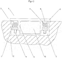
- the wall bracket according to the invention is generally identified in the figures with the reference number 1 and comprises a stationary part 2 and a removable part 3.
- the stationary part 2 comprises a socket (not shown in more detail) that can be inserted into a recess in a building wall and a metal plate 4.
- the metal plate is arranged below a receiving area 5 for an electronic device or for electronic components and protrudes over this area 5 on all sides.
- the removable part 3 has a cover plate 6, which consists of glass, covers the receiving area 5 and also protrudes over this on all sides.
- each side wall of the frame-shaped connecting part 7 there is a bore 8 which is perpendicular to the plane of the cover plate 6 and in which an axially displaceable holding magnet 9 is arranged, approximately halfway.
- the holding magnet is a permanent magnet.
- the bore 8 is round in cross section and the holding magnet 9 is cylindrical, so that although it is along the axis can be moved and rotated around the axis, but cannot be rotated off the axis.
- the reference numeral 10 denotes an assembly tool which is only shown schematically with the aid of a single release magnet 11.
- the assembly tool 10 also includes a plurality of release magnets 11 corresponding to the different holding magnets 9 in the removable part 3, as well as a handle.
- Figure 1 shows the holding device according to the invention in a closed position, the holding magnets 9 being at the end of the bores 8 on the mounting plate side.
- This position of the holding magnets 9 is essentially enforced by the magnetic attraction between the permanent magnetic holding elements 9 and the metallic iron or iron alloy plate 4. Due to the proximity of the holding magnets 9 to the mounting plate 4, the interaction between these two elements is relatively strong, which means that the removable part 3 (which is only fixed magnetically on the stationary part 2) can only be removed by overcoming a relatively large force, namely the force of attraction between the Holding magnets 9 and the mounting plate 4.
- the magnetic or magnetizable elements 4, 9 and 11 are designed so that the magnetic force of attraction between the release magnets 11 and holding magnets 9 is stronger than the magnetic force of attraction between holding magnets 9 and mounting plate 4, although initially there is an additional distance between holding magnets 9 and release magnets 11 due to the freedom of movement of holding magnets 9. Therefore pull the release magnets 11 of the assembly tool 10 Holding magnets 9 away from the mounting plate 4 and the holding magnets 9 move linearly within the bore 8 in the direction of the cover plate.
- the removal of the removable part 3 can serve, for example, to remove or insert an electronic device into the receiving area 5 or to access electronics arranged in the receiving area 5. It can also be used to lay and connect lines within the stationary part 2, on the electronic component or on the removable part 3.
- any other functional and display inserts can be located in the receiving area 5 below the cover plate 6, which e.g. include display and / or control electronics. It is particularly preferred, regardless of the device or the type of electronics, if the device or the electronics have an illuminated and touch-sensitive user interface (a touchscreen).
- the removable part 3 which adheres magnetically to the assembly tool 10
- the removable part 3 can be placed on the stationary part 2 and also pressed onto it by hand. It can then be removed by overcoming the magnetic force of attraction between the release magnet 11 and the holding magnet 9, while the removable part 3 is manually pressed against the stationary part 2.
- the holding magnets 9 within the bore 8 are again in the direction of the mounting plate 4 and thus in the in Figure 1 shown starting position pulled.
- FIG. 3 shows a further embodiment of a wall bracket 1 according to the invention in a closed position, with the embodiment according to FIG Figures 1 and 2 Corresponding components are provided with the same reference numerals.
- the stationary part 2 is designed in the form of a flush-mounted housing, which has several point-shaped assembly elements in the form of magnetizable metal and, for example, iron screws 4.
- the holding magnets 9 within the removable part 3 are arranged at positions within the connecting part 7 that correspond to the screws 4.
- the use of screws 4 as assembly elements has the advantage that the depth of the screw heads can be individually adjusted by turning the screws 4 in or out, which enables plaster compensation during assembly.
Landscapes
- Engineering & Computer Science (AREA)
- General Engineering & Computer Science (AREA)
- Mechanical Engineering (AREA)
- Casings For Electric Apparatus (AREA)
Description
- Die Erfindung betrifft eine Wandhalterung für elektronische Bauteile.
- Immer häufiger werden Bedienelemente oder Anzeigen mit beispielsweise berührungsempfindlichen Anzeigeschirmen zur Steuerung der Gebäudeelektronik verwendet, sei es zur Regulierung der Heizung oder allgemein des Raumklimas, zur Steuerung elektrischer Rolläden oder allgemein Sicht- und Sonnenschutzvorrichtungen, zur Steuerung der Beleuchtung oder dergleichen. Dabei kann es wünschenswert sein, diese Bedienelemente oder Anzeigen zu überdecken und an der Wand zu halten. Eine herkömmliche Wandhalterung ist aus der
DE202015006172U1 bekannt. - Ziel der Erfindung ist es, eine Wandhalterung bereitzustellen, die formschön ist und eine Abdeckung und Bedienung der elektronischen Bauteile und einen einfachen Zugriff durch einen Techniker ermöglicht. Zudem soll das Bauteil vor einem unbefugten Zugriff geschützt sein.
- Vor diesem Hintergrund betrifft die Erfindung eine Wandhalterung gemäß Anspruch 1.
- So wird das abnehmbare Teil durch die Anziehungskraft zwischen Haltemagneten und Montageelementen am stationären Teil gehalten. Diese Anziehungskraft ist stark genug, um zu verhindern, dass das abnehmbare Teil unbefugt vom Rahmen abgezogen wird, insbesondere dann, wenn die Abdeckplatte und, wie in der Einbausituation bevorzugt, der Umfangsbereich der Abdeckplatte keine Angriffspunkte für eine Entnahme aufweisen. Eine einfache Abnahme kann durch Annäherung eines Montagewerkzeugs mit Lösemagneten erreicht werden, der stärker mit den Haltemagneten wechselwirkt als die Montageelemente (also beispielsweise selbst permanentmagnetisch oder stärker permanentmagnetisch als die Montageelemente ist). Denn dann werden die Haltemagnete von den Montageelementen weggezogen und deren Wechselwirkung durch den vergrößerten Abstand geringer. Gleichzeitig haftet das Montagewerkzeug magnetisch an den Haltemagneten und somit am abnehmbaren Teil und kann dazu verwendet werden, die das abnehmbare Teil samt Abdeckplatte unter Überwindung der verbleibenden Anziehungskraft zwischen Haltemagneten und Montageelementen abzuziehen.
- Es reicht aus, wenn entweder Haltemagnete oder Montageelemente magnetisch sind, während die jeweils anderen Elemente lediglich magnetisierbar sind. So können beispielsweise die Haltemagnete nicht permanentmagnetisch sondern lediglich magnetisierbar sein, während die Montageelemente permanentmagnetisch sind. Bevorzugt ist allerdings, dass die Haltemagnete permanentmagnetisch und die Montageelemente magnetisierbar sind. Ein geeignetes magnetisches oder magnetisierbares Material umfasst ein Metall und insbesondere Eisen oder eine Eisenlegierungen.
- In einer Ausführungsform umfasst das abnehmbare Teil mehrere um den Aufnahmebereich verteilte Haltemagnete.
- In einer Ausführungsform umfasst das stationäre Teil ein flächiges Montageelement für die Haltemagnete. Beispielsweise handelt es sich bei dem Montageelement um einen vorzugsweise rechteckigen metallischen Rahmen, der den Aufnahmebereich umgibt. Ferner kann es sich bei dem Montageelement um eine Metallplatte handeln, die unterhalb des Aufnahmebereichs sitzt.
- In einer Ausführungsform umfasst das stationäre Teil mehrere punktförmige Montageelemente für jeweils einen Haltemagnet, wobei die Montageelemente und die Haltemagnete an korrespondierenden Positionen angeordnet sind. Beispielsweise handelt es sich bei den Montageelementen um mehrere um den Aufnahmebereich verteilte punktförmige Bauteile wie Stifte, Schrauben, Bolzen oder Knöpfe. Die Montageelemente können in einem Sockel angeordnet sein, der den Aufnahmebereich umgibt.
- In einer Ausführungsform umfasst das abnehmbare Teil ein Verbindungsteil, das an der Innenseite der Abdeckplatte angebracht ist, beispielsweise mit einer Klebe- oder Schraubverbindung. Das Verbindungsteil kann in dieser Ausführungsform die Haltemagnete aufnehmen. Das Verbindungsteil kann beispielsweise die Form eines beispielsweise rechteckigen Rahmens haben, der den Aufnahmebereich umgibt.
- In einer Ausführungsform umfasst die Wandhalterung vier oder mehr Haltemagnete, die beispielsweise mittig im Bereich der Seitenwände oder im Bereich der Ecken des als Rahmen ausgebildeten Verbindungsteils angeordnet sind.
- In einer Ausführungsform sind die Haltemagneten so im abnehmbaren Teil gelagert, dass sie auf einer linearen Bahn normal zur Ebene der Abdeckplatte hin und her bewegt werden können.
- In einer Ausführungsform weist das abnehmbare Teil und insbesondere das Verbindungsteil Bohrungen auf, in denen die Haltemagnete aufgenommen sind und die als Führungen für die Bewegung der Haltemagnete dienen. Die Bohrungen verlaufen vorzugsweise linear und normal zur Ebene der Abdeckplatte. Der Querschnitt der Bohrungen kann beispielsweise rund sein. Runde Bohrungen lassen sich am einfachsten herstellen.
- In einer Ausführungsform handelt es sich bei den Haltemagneten um kreiszylindrische Magnetknöpfe, deren Durchmesser in etwa dem Innendurchmesser der Bohrungen entspricht, sodass diese in den Bohrungen nur entlang der Achse verschoben und um die Achse gedreht, nicht jedoch aus der Achse gedreht werden können. So kann sichergestellt werden, dass sich die Richtung der magnetischen Orientierung nicht ändert.
- In einer Ausführungsform handelt es sich bei der Abdeckplatte um eine Glasplatte oder um eine durchsichtige Kunststoffplatte.
- In einer Ausführungsform ist die Abdeckplatte nicht als durchgehende Platte ausgebildet, sondern weist im Bereich oberhalb des Aufnahmebereichs ein Fenster auf, durch das ein im Aufnahmebereich befindliches Bauteil direkt, d.h., ohne zwischengelagerte Platte bedient werden kann. In diesem Fall überdeckt die Abdeckplatte beispielsweise alle Seitenkanten des Bauteils, um eine unbefugte Entnahme oder ein zufälliges Herausfallen zu verhindern.
- Vor dem eingangs genannten Hintergrund betrifft die Erfindung ferner ein Verfahren zur Abnahme des abnehmbaren Teils vom stationären Teil einer erfindungsgemäßen Wandhalterung, wobei ein Montagewerkzeug, das wenigstens einen Lösemagneten umfasst, an die Abdeckplatte angenähert wird, und wobei die Lösemagnete stärker auf die Haltemagnete wirken als die Montageelemente.
- In einer Ausführungsform umfasst das Montagewerkzeug mehrere punktförmige Lösemagneten für jeweils einen Haltemagnet, wobei die Lösemagneten innerhalb des Montagewerkzeugs in derselben relativen Position zueinander angeordnet sind wie die Haltemagnete in der Wandhalterung. Alternativ kann das Montagewerkzeug einen ein- oder mehrteiligen flächigen Lösemagneten aufweisen, dessen Verlauf innerhalb des Montagewerkzeugs so ist, dass dessen Verlauf Punkte umfasst, deren relative Position zueinander so ist wie die der Haltemagnete in der Wandhalterung. So wird erreicht, dass bei Annäherung des Montagewerkzeugs an die Abdeckplatte alle Haltemagnete gleichzeitig von den Montageelementen weggezogen werden.
- Beispielsweise kann das Montagewerkzeug gleich viele Lösemagneten umfassen wie das abnehmbare Teil Haltemagnete.
- In einer Ausführungsform umfasst das Montagewerkzeug einen Griff. Dies erleichtert die Verwendung zum Abziehen des abnehmbaren Teils.
- Das Abnehmen des abnehmbaren Teils kann dazu dienen, Zugriff zur Elektronik zu erlangen oder beispielsweise ein elektronisches Bauteil in den Aufnahmebereich einzulegen oder es daraus zu entnehmen.
- Die Erfindung betrifft auch ein System umfassend eine erfindungsgemäße Wandhalterung und ein Montagewerkzeug, wie sie im Zusammenhang mit dem erfindungsgemäßen Verfahren beschrieben ist.
- Die Erfindung umfasst auch die erfindungsgemäße Wandhalterung mit einer hinter der Abdeckplatte im Aufnahmebereich befindlichen Elektronik oder mit einem in den Aufnahmebereich eingelegten elektronischen Bauteil. Geeignete Elektronikbauteile weisen vorzugsweise einen Touchscreen auf, der durch die Abdeckplatte hindurch bedient werden kann. Beispiele für geeignete Geräte, die als eigenständig funktionsfähiges Ganzes entnommen werden können, umfassen Smartphones oder Tablets.
- Letztlich betrifft die Erfindung auch ein Gebäude mit einer Wand und einer in einer Ausnehmung der Wand angeordneten erfindungsgemäßen Wandhalterung. Vorzugsweise ist dabei vorgesehen, dass die Außenoberfläche der Abdeckplatte mit der Ebene der Wand fluchtet.
- So wird kein Angriffspunkt gegeben, um die Abdeckplatte unter Überwindung der Anziehungskraft zwischen Haltemagneten und Montageelementen und ohne die Hilfe eines geeigneten magnetischen Montagewerkzeugs abzuziehen.
- Weitere Einzelheiten und Vorteile der Erfindung ergeben sich aus dem nachfolgend anhand der Figuren beschriebenen Ausführungsbeispiel. In den Figuren zeigen:
- Figur 1:
- eine erfindungsgemäße Wandhalterung nebst Montagewerkzeug in einer geschlossenen Stellung;
- Figur 2:
- eine erfindungsgemäße Wandhalterung nebst Montagewerkzeug in einer geöffneten Stellung; und
- Figur 3:
- eine weitere Ausführungsform einer erfindungsgemäßen Wandhalterung in einer geschlossenen Stellung.
- Die erfindungsgemäße Wandhalterung ist in den Figuren allgemein mit dem Bezugszeichen 1 gekennzeichnet und umfasst ein stationäres Teil 2 und ein abnehmbares Teil 3.
- Das stationäre Teil 2 umfasst eine nicht näher dargestellte und in einer Ausnehmung einer Gebäudewand einlegbare Fassung und eine Metallplatte 4. Die Metallplatte ist unterhalb eines Aufnahmebereichs 5 für ein elektronisches Gerät oder für Elektronikbauteile angeordnet und steht auf allen Seiten über diesen Bereich 5 über.
- Das abnehmbare Teil 3 weist eine Abdeckplatte 6 auf, die aus Glas besteht, den Aufnahmebereich 5 überdeckt und ebenfalls auf allen Seiten über diesen übersteht. An der Innenseite der Abdeckplatte 6 ist ein rahmenförmiges Verbindungsteil 7 aufgeklebt, welches den Aufnahmebereich 5 auf allen Seiten umgibt.
- In jeder Seitenwand des rahmenförmigen Verbindungsteils 7 befindet sich auf etwa halbem Weg eine normal auf die Ebene der Abdeckplatte 6 stehende Bohrung 8, in welcher ein axial verschieblicher Haltemagnet 9 angeordnet ist. Bei dem Haltemagneten handelt es sich um einen Permanentmagneten. Die Bohrung 8 ist im Querschnitt rund und der Haltemagnet 9 ist zylindrisch, sodass er zwar entlang der Achse verschoben und um die Achse gedreht werden kann, jedoch nicht aus der Achse gedreht werden kann.
- Mit dem Bezugszeichen 10 ist ein Montagewerkzeug gekennzeichnet, das lediglich schematisch anhand eines einzigen Lösemagneten 11 dargestellt ist. Das Montagewerkzeug 10 umfasst jedoch weiterhin mehrere zu den unterschiedlichen Haltemagneten 9 im abnehmbaren Teil 3 korrespondierende Lösemagneten 11 sowie einen Haltegriff.
-
Figur 1 zeigt die erfindungsgemäße Haltevorrichtung in einer geschlossenen Stellung, wobei sich die Haltemagneten 9 am montageplattenseitigen Ende der Bohrungen 8 befinden. Diese Position der Haltemagneten 9 wird im Wesentlichen durch die magnetische Anziehung zwischen dem permanentmagnetischen Halteelementen 9 und der metallischen Eisen- oder Eisenlegierungsplatte 4 erzwungen. Durch die Nähe der Haltemagneten 9 zur Montageplatte 4 ist die Wechselwirkung zwischen diesen beiden Elementen relativ stark, wodurch ein Abnehmen des (nur magnetisch am stationären Teil 2 fixierten) abnehmbaren Teils 3 nur unter Überwindung einer relativ großen Kraft möglich ist, nämlich der Anziehungskraft zwischen den Haltemagneten 9 und der Montageplatte 4. - Wird das Montagewerkzeug 10 mit seinen Lösemagneten 11 auf die Montageplatte 6 gelegt, kommt es zu einer magnetischen Wechselwirkung zwischen den Lösemagneten 11 und den Haltemagneten 9. Die magnetischen bzw. magnetisierbaren Elemente 4, 9 und 11 sind so ausgebildet, dass die magnetische Anziehungskraft zwischen Lösemagneten 11 und Haltemagneten 9 stärker ist als die magnetische Anziehungskraft zwischen Haltemagneten 9 und Montageplatte 4, obwohl sich anfangs durch den Bewegungsspielraum der Haltemagneten 9 noch ein zusätzlicher Abstand zwischen den Haltemagneten 9 und den Lösemagneten 11 ergibt. Daher ziehen die Lösemagneten 11 des Montagewerkzeugs 10 die Haltemagneten 9 von der Montageplatte 4 weg und die Haltemagneten 9 verschieben sich innerhalb der Bohrung 8 linear in Richtung der Abdeckplatte. Dies führt einerseits dazu, dass das Montagewerkzeug 10 magnetisch am abnehmbaren Teil 3 haftet, und es bewirkt zudem, dass durch die nun größere Entfernung die magnetische Anziehungskraft zwischen den Haltemagneten 9 und der Abdeckplatte 4 gering ist. Daher kann mit dem Montagewerkzeug 10, dessen magnetische Haftung am abnehmbaren Teil 3 nun stärker ist als die Haftung des abnehmbaren Teils 3 am stationären Teil 2, dazu verwendet werden, das abnehmbare Teil 3 abzuziehen. Dies ist in
Figur 2 dargestellt. - Die Abnahme des abnehmbaren Teils 3 kann beispielsweise der Entnahme oder dem Einlegen eines elektronischen Gerätes in den Aufnahmebereich 5 bzw. dem Zugriff zu einer in dem Aufnahmebereich 5 angeordneten Elektronik dienen. Ferner kann sie dem Verlegen und Anschließen von Leitungen innerhalb des stationären Teils 2, an dem Elektronikbauteil oder an dem abnehmbaren Teil 3 dienen. An Stelle eines elektronischen Geräts, das als eigenständig funktionsfähiges Ganzes entnommen werden kann, können sich beliebige andere Funktions- und Anzeigeeinsätze im Aufnahmebereich 5 unterhalb der Abdeckplatte 6 befinden, die z.B. eine Anzeige- und/oder Bedienelektronik umfassen. Besonders bevorzugt ist es unabhängig vom Gerät oder von der Art der Elektronik, wenn das Gerät oder die Elektronik eine beleuchtete und berührungsempfindliche Bedienoberfläche (einen Touchscreen) aufweist.
- Um das abnehmbare Teil 3 wieder auf das stationäre Teil 2 aufzusetzen und wiederum den Zustand der
Figur 1 zu erreichen, kann das abnehmbare Teil 3, das magnetisch am Montagewerkzeug 10 anhaftet, auf das stationäre Teil 2 aufgesetzt und zudem händisch auf dieses aufgedrückt werden. Anschließend kann es unter Überwindung der magnetischen Anziehungskraft zwischen Lösemagneten 11 und Haltemagneten 9 abgezogen werden kann, während das abnehmbare Teil 3 manuell an das stationäre Teil 2 gedrückt wird. Sobald das Montagewerkzeug vom abnehmbaren Teil entfernt wurde, werden die Haltemagneten 9 innerhalb der Bohrung 8 wieder in Richtung der Montageplatte 4 und somit in die inFigur 1 dargestellte Ausgangsposition gezogen. -
Figur 3 zeigt eine weitere Ausführungsform einer erfindungsgemäßen Wandhalterung 1 in einer geschlossenen Stellung, wobei zu den der Ausführungsform gemäßFiguren 1 und2 korrespondierende Bauteile mit gleichen Bezugszeichen versehen sind. - Das stationäre Teil 2 ist hierbei in Form eines Unterputzgehäuses ausgebildet, welches mehrere punktförmige Montageelemente in Form von magnetisierbaren Metall- und beispielsweise Eisenschrauben 4 aufweist. Die Haltemagnete 9 innerhalb des abnehmbaren Teils 3 sind an zu den Schrauben 4 korrespondierenden Positionen innerhalb des Verbindungsteils 7 angeordnet. Die Verwendung von Schrauben 4 als Montageelemente hat den Vorteil, dass die Tiefe der Schraubenköpfe durch ein Ein- bzw. Ausdrehen der Schrauben 4 individuell angepasst werden kann, was einen Putzausgleich bei der Montage ermöglicht.
- In der Ausführungsform gemäß
Figur 3 sind neben den bereits inFiguren 1 und2 sichtbaren Elementen auch noch die Wand 12 und ein in den Aufnahmebereich 5 eingelegt Gerät 13 abgebildet.
Claims (10)
- Wandhalterung (1) für ein elektronisches Bauteil mit einem stationären Teil (2), einem abnehmbaren Teil (3), das eine Abdeckplatte (6) aufweist, und einem zwischen dem stationären Teil (2) und der Abdeckplatte (6) liegenden Aufnahmebereich (5) für das elektronische Bauteil, wobei das abnehmbare Teil (3) lösbar auf dem stationären Teil (3) aufliegt und die Abdeckplatte (6) im aufliegenden Zustand den Aufnahmebereich (5) überdeckt, dadurch gekennzeichnet, dass das abnehmbare Teil (3) wenigstens einen Haltemagneten (9) und das stationäre Teil (2) wenigstens ein magnetisches oder magnetisierbares Montageelement (4) aufweist, um die Haltemagnete (9) anzuziehen, wobei die Haltemagnete (9) derart beweglich im abnehmbaren Teil (3) gelagert sind, dass deren Abstand zu den Montageelementen (4) verändert werden kann, während das abnehmbare Teil (3) auf dem stationären Teil (2) aufliegt.
- Wandhalterung nach Anspruch 1, dadurch gekennzeichnet, dass die Haltemagnete (9) permanentmagnetisch und die Montageelemente (4) magnetisierbar sind.
- Wandhalterung nach einem der vorhergehenden Ansprüche, dadurch gekennzeichnet, dass das abnehmbare Teil (3) mehrere um den Aufnahmebereich (5) verteilte Haltemagnete (9) umfasst.
- Wandhalterung nach einem der vorhergehenden Ansprüche, dadurch gekennzeichnet, dass das stationäre Teil (2) ein flächiges Montageelement (4) umfasst, das die Haltemagnete (9) anzieht.
- Wandhalterung nach einem der Ansprüche 1 bis 3, dadurch gekennzeichnet, dass das stationäre Teil (2) mehrere punktförmige Montageelemente (4) für jeweils einen Haltemagneten (9) umfasst, wobei die Montageelemente (4) und die Haltemagnete (9) an korrespondierenden Positionen angeordnet sind.
- Wandhalterung nach einem der vorhergehenden Ansprüche, dadurch gekennzeichnet, dass das abnehmbare Teil (3) ein Verbindungsteil (7), vorzugsweise einen Rahmen (7) umfasst, das an der Innenseite der Abdeckplatte (6) angebracht ist und in dem die Haltemagnete (9) aufgenommen sind.
- Wandhalterung nach einem der vorhergehenden Ansprüche, dadurch gekennzeichnet, dass die Haltemagnete (9) so im abnehmbaren Teil gelagert sind, dass sie auf einer linearen Bahn normal zur Ebene der Abdeckplatte (6) hin und her bewegt werden können.
- Wandhalterung nach einem der vorhergehenden Ansprüche, dadurch gekennzeichnet, dass das abnehmbare Teil (3) und insbesondere das Verbindungsteil (7) Bohrungen (8) aufweist, in denen die Haltemagnete (9) aufgenommen sind, wobei die Bohrungen (8) vorzugsweise linear und normal zur Ebene der Abdeckplatte (6) verlaufen und wobei der Querschnitt der Bohrungen (8) vorzugsweise rund ist.
- Wandhalterung nach einem der vorhergehenden Ansprüche, dadurch gekennzeichnet, dass es sich bei den Haltemagneten (9) um kreiszylindrische Magnetknöpfe handelt, deren Durchmesser vorzugsweise in etwa dem Innendurchmesser der Bohrungen (8) entspricht.
- Verfahren zur Abnahme des abnehmbaren Teils (3) vom stationären Teil (2) einer Wandhalterung (1) nach einem der vorhergehenden Ansprüche,
dadurch gekennzeichnet,
dass ein Montagewerkzeug (10), das wenigstens einen Lösemagneten (11) umfasst, an die Abdeckplatte (6) angenähert wird, wobei die Lösemagnete (11) stärker auf die Haltemagnete (9) wirken als die Montageelemente (4).
Applications Claiming Priority (1)
| Application Number | Priority Date | Filing Date | Title |
|---|---|---|---|
| DE102016002739.8A DE102016002739A1 (de) | 2016-03-08 | 2016-03-08 | Wandhalterung für elektronische Bauteile |
Publications (2)
| Publication Number | Publication Date |
|---|---|
| EP3216367A1 EP3216367A1 (de) | 2017-09-13 |
| EP3216367B1 true EP3216367B1 (de) | 2021-08-18 |
Family
ID=58227903
Family Applications (1)
| Application Number | Title | Priority Date | Filing Date |
|---|---|---|---|
| EP17157114.4A Active EP3216367B1 (de) | 2016-03-08 | 2017-02-21 | Wandhalterung für elektronische bauteile |
Country Status (2)
| Country | Link |
|---|---|
| EP (1) | EP3216367B1 (de) |
| DE (1) | DE102016002739A1 (de) |
Families Citing this family (2)
| Publication number | Priority date | Publication date | Assignee | Title |
|---|---|---|---|---|
| DE102018101210B4 (de) | 2018-01-19 | 2019-08-22 | Fujitsu Client Computing Limited | Wandbefestigung für eine elektronische Anzeige, Computeranordnung und Verfahren zur Montage einer elektronischen Anzeige und eines Computersystems an einer Wand |
| DE202018001427U1 (de) | 2018-03-16 | 2019-06-18 | Controltronic Gmbh | Ein- und/oder Ausgabegerät mit hinterleuchteter Deckplatte |
Family Cites Families (4)
| Publication number | Priority date | Publication date | Assignee | Title |
|---|---|---|---|---|
| KR102043345B1 (ko) * | 2013-02-21 | 2019-11-11 | 엘지디스플레이 주식회사 | 디스플레이 장치의 벽면 고정 구조 |
| US8944826B1 (en) * | 2013-07-16 | 2015-02-03 | Curbell Medical Products, Inc. | Magnetic connection for cable assembly of electronic device |
| DE202015001146U1 (de) * | 2015-02-16 | 2015-03-09 | Daniel Thätner | Wandhaltesystem für mobile Endgeräte (Computer-Tablets & Smartphones) |
| DE202015006172U1 (de) * | 2015-09-01 | 2015-12-04 | Wan Chieh WU | Kombinierbare Mehrzweck-Wandhalterung zum Aufhängen von Gegenständen |
-
2016
- 2016-03-08 DE DE102016002739.8A patent/DE102016002739A1/de not_active Withdrawn
-
2017
- 2017-02-21 EP EP17157114.4A patent/EP3216367B1/de active Active
Non-Patent Citations (1)
| Title |
|---|
| None * |
Also Published As
| Publication number | Publication date |
|---|---|
| EP3216367A1 (de) | 2017-09-13 |
| DE102016002739A1 (de) | 2017-09-14 |
Similar Documents
| Publication | Publication Date | Title |
|---|---|---|
| EP2250334B1 (de) | Vorrichtung zum feststellen von türen mittels magnetischer anziehung | |
| EP3216367B1 (de) | Wandhalterung für elektronische bauteile | |
| EP4201548A1 (de) | Stanzwerkzeug | |
| DE10242467A1 (de) | Vorrichtung zur Unterbringung eines elektrischen Geräts im Innenraum eines Kraftfahrzeugs | |
| DE10261523A1 (de) | Vitrine zur Zurschaustellung von Gegenständen | |
| DE19530429C1 (de) | Hohlkörper für die Elektroinstallation | |
| DE202012012220U1 (de) | Frei positionierbarer Magnetgriff | |
| EP3661176A1 (de) | Magnetischer blickschutzfilter | |
| DE202011004757U1 (de) | Zusätzlicher elektromechanischer Verschluss für Gehäuse, geeignet zur Unterbringung im Abkantungsraum von Blechschranktüren und Blechschrankrahmen und -Gehäusen | |
| EP3153642A1 (de) | Einbausystem für leuchten | |
| DE202007016981U1 (de) | Befestigungsvorrichtung für ein elektrotechnisches Bauteil | |
| EP3344927B1 (de) | Abschlusseinheit für einen luftdurchlass | |
| DE202011106151U1 (de) | Magnettafelanordnung zur Befestigung an einer Wand | |
| EP2905524A1 (de) | Haltevorrichtung zum Halten eines elektronischen Gerätes an einer Wand | |
| DE102010034339B4 (de) | Befestigungsset für elektronische Geräte | |
| DE3241407C1 (de) | Anzeige- und Bedientableau fuer Aufzugkabinen | |
| EP2634357B9 (de) | Insektenschutzvorrichtung und Positionierhilfe zu deren Positionierung | |
| EP3020904B1 (de) | Abdeckvorrichtung für die Abdeckung einer Rollenlaufbahn einer Schiebetürenanlage | |
| EP4453686A1 (de) | Magnetisch gehaltertes nutzerschnittstellengerät und set hierfür | |
| EP2706634B1 (de) | Elektrisches / elektronisches installationsgerät mit einem abdeckrahmen | |
| EP4470868A1 (de) | Schienenfahrzeug mit fahrzeugkomponente und befestigungsverfahren | |
| DE202009004151U1 (de) | Tür- oder Hinweisschild sowie Einrichtung zur Diebstahlsicherung für ein solches Tür- oder Hinweisschild | |
| DE102009024470A1 (de) | Abdeckung mit innenliegender Fixierung | |
| EP1922454B1 (de) | Verkleidungssystem mit berührungsloser ver- und entriegelung | |
| EP3879551A1 (de) | Elektrisches schaltgerät für die elektrische gebäudeinstallation und ein entsprechendes verfahren |
Legal Events
| Date | Code | Title | Description |
|---|---|---|---|
| PUAI | Public reference made under article 153(3) epc to a published international application that has entered the european phase |
Free format text: ORIGINAL CODE: 0009012 |
|
| STAA | Information on the status of an ep patent application or granted ep patent |
Free format text: STATUS: THE APPLICATION HAS BEEN PUBLISHED |
|
| AK | Designated contracting states |
Kind code of ref document: A1 Designated state(s): AL AT BE BG CH CY CZ DE DK EE ES FI FR GB GR HR HU IE IS IT LI LT LU LV MC MK MT NL NO PL PT RO RS SE SI SK SM TR |
|
| AX | Request for extension of the european patent |
Extension state: BA ME |
|
| STAA | Information on the status of an ep patent application or granted ep patent |
Free format text: STATUS: REQUEST FOR EXAMINATION WAS MADE |
|
| 17P | Request for examination filed |
Effective date: 20180313 |
|
| RBV | Designated contracting states (corrected) |
Designated state(s): AL AT BE BG CH CY CZ DE DK EE ES FI FR GB GR HR HU IE IS IT LI LT LU LV MC MK MT NL NO PL PT RO RS SE SI SK SM TR |
|
| STAA | Information on the status of an ep patent application or granted ep patent |
Free format text: STATUS: EXAMINATION IS IN PROGRESS |
|
| 17Q | First examination report despatched |
Effective date: 20190710 |
|
| GRAP | Despatch of communication of intention to grant a patent |
Free format text: ORIGINAL CODE: EPIDOSNIGR1 |
|
| STAA | Information on the status of an ep patent application or granted ep patent |
Free format text: STATUS: GRANT OF PATENT IS INTENDED |
|
| INTG | Intention to grant announced |
Effective date: 20210303 |
|
| GRAS | Grant fee paid |
Free format text: ORIGINAL CODE: EPIDOSNIGR3 |
|
| GRAA | (expected) grant |
Free format text: ORIGINAL CODE: 0009210 |
|
| STAA | Information on the status of an ep patent application or granted ep patent |
Free format text: STATUS: THE PATENT HAS BEEN GRANTED |
|
| AK | Designated contracting states |
Kind code of ref document: B1 Designated state(s): AL AT BE BG CH CY CZ DE DK EE ES FI FR GB GR HR HU IE IS IT LI LT LU LV MC MK MT NL NO PL PT RO RS SE SI SK SM TR |
|
| REG | Reference to a national code |
Ref country code: GB Ref legal event code: FG4D Free format text: NOT ENGLISH |
|
| REG | Reference to a national code |
Ref country code: CH Ref legal event code: EP |
|
| REG | Reference to a national code |
Ref country code: DE Ref legal event code: R096 Ref document number: 502017011205 Country of ref document: DE |
|
| REG | Reference to a national code |
Ref country code: IE Ref legal event code: FG4D Free format text: LANGUAGE OF EP DOCUMENT: GERMAN Ref country code: AT Ref legal event code: REF Ref document number: 1420825 Country of ref document: AT Kind code of ref document: T Effective date: 20210915 |
|
| REG | Reference to a national code |
Ref country code: LT Ref legal event code: MG9D |
|
| REG | Reference to a national code |
Ref country code: NL Ref legal event code: MP Effective date: 20210818 |
|
| PG25 | Lapsed in a contracting state [announced via postgrant information from national office to epo] |
Ref country code: HR Free format text: LAPSE BECAUSE OF FAILURE TO SUBMIT A TRANSLATION OF THE DESCRIPTION OR TO PAY THE FEE WITHIN THE PRESCRIBED TIME-LIMIT Effective date: 20210818 Ref country code: ES Free format text: LAPSE BECAUSE OF FAILURE TO SUBMIT A TRANSLATION OF THE DESCRIPTION OR TO PAY THE FEE WITHIN THE PRESCRIBED TIME-LIMIT Effective date: 20210818 Ref country code: FI Free format text: LAPSE BECAUSE OF FAILURE TO SUBMIT A TRANSLATION OF THE DESCRIPTION OR TO PAY THE FEE WITHIN THE PRESCRIBED TIME-LIMIT Effective date: 20210818 Ref country code: PT Free format text: LAPSE BECAUSE OF FAILURE TO SUBMIT A TRANSLATION OF THE DESCRIPTION OR TO PAY THE FEE WITHIN THE PRESCRIBED TIME-LIMIT Effective date: 20211220 Ref country code: NO Free format text: LAPSE BECAUSE OF FAILURE TO SUBMIT A TRANSLATION OF THE DESCRIPTION OR TO PAY THE FEE WITHIN THE PRESCRIBED TIME-LIMIT Effective date: 20211118 Ref country code: LT Free format text: LAPSE BECAUSE OF FAILURE TO SUBMIT A TRANSLATION OF THE DESCRIPTION OR TO PAY THE FEE WITHIN THE PRESCRIBED TIME-LIMIT Effective date: 20210818 Ref country code: BG Free format text: LAPSE BECAUSE OF FAILURE TO SUBMIT A TRANSLATION OF THE DESCRIPTION OR TO PAY THE FEE WITHIN THE PRESCRIBED TIME-LIMIT Effective date: 20211118 Ref country code: SE Free format text: LAPSE BECAUSE OF FAILURE TO SUBMIT A TRANSLATION OF THE DESCRIPTION OR TO PAY THE FEE WITHIN THE PRESCRIBED TIME-LIMIT Effective date: 20210818 Ref country code: RS Free format text: LAPSE BECAUSE OF FAILURE TO SUBMIT A TRANSLATION OF THE DESCRIPTION OR TO PAY THE FEE WITHIN THE PRESCRIBED TIME-LIMIT Effective date: 20210818 |
|
| PG25 | Lapsed in a contracting state [announced via postgrant information from national office to epo] |
Ref country code: PL Free format text: LAPSE BECAUSE OF FAILURE TO SUBMIT A TRANSLATION OF THE DESCRIPTION OR TO PAY THE FEE WITHIN THE PRESCRIBED TIME-LIMIT Effective date: 20210818 Ref country code: LV Free format text: LAPSE BECAUSE OF FAILURE TO SUBMIT A TRANSLATION OF THE DESCRIPTION OR TO PAY THE FEE WITHIN THE PRESCRIBED TIME-LIMIT Effective date: 20210818 Ref country code: GR Free format text: LAPSE BECAUSE OF FAILURE TO SUBMIT A TRANSLATION OF THE DESCRIPTION OR TO PAY THE FEE WITHIN THE PRESCRIBED TIME-LIMIT Effective date: 20211119 |
|
| PG25 | Lapsed in a contracting state [announced via postgrant information from national office to epo] |
Ref country code: NL Free format text: LAPSE BECAUSE OF FAILURE TO SUBMIT A TRANSLATION OF THE DESCRIPTION OR TO PAY THE FEE WITHIN THE PRESCRIBED TIME-LIMIT Effective date: 20210818 |
|
| PG25 | Lapsed in a contracting state [announced via postgrant information from national office to epo] |
Ref country code: DK Free format text: LAPSE BECAUSE OF FAILURE TO SUBMIT A TRANSLATION OF THE DESCRIPTION OR TO PAY THE FEE WITHIN THE PRESCRIBED TIME-LIMIT Effective date: 20210818 |
|
| REG | Reference to a national code |
Ref country code: DE Ref legal event code: R097 Ref document number: 502017011205 Country of ref document: DE |
|
| PG25 | Lapsed in a contracting state [announced via postgrant information from national office to epo] |
Ref country code: SM Free format text: LAPSE BECAUSE OF FAILURE TO SUBMIT A TRANSLATION OF THE DESCRIPTION OR TO PAY THE FEE WITHIN THE PRESCRIBED TIME-LIMIT Effective date: 20210818 Ref country code: SK Free format text: LAPSE BECAUSE OF FAILURE TO SUBMIT A TRANSLATION OF THE DESCRIPTION OR TO PAY THE FEE WITHIN THE PRESCRIBED TIME-LIMIT Effective date: 20210818 Ref country code: RO Free format text: LAPSE BECAUSE OF FAILURE TO SUBMIT A TRANSLATION OF THE DESCRIPTION OR TO PAY THE FEE WITHIN THE PRESCRIBED TIME-LIMIT Effective date: 20210818 Ref country code: EE Free format text: LAPSE BECAUSE OF FAILURE TO SUBMIT A TRANSLATION OF THE DESCRIPTION OR TO PAY THE FEE WITHIN THE PRESCRIBED TIME-LIMIT Effective date: 20210818 Ref country code: CZ Free format text: LAPSE BECAUSE OF FAILURE TO SUBMIT A TRANSLATION OF THE DESCRIPTION OR TO PAY THE FEE WITHIN THE PRESCRIBED TIME-LIMIT Effective date: 20210818 Ref country code: AL Free format text: LAPSE BECAUSE OF FAILURE TO SUBMIT A TRANSLATION OF THE DESCRIPTION OR TO PAY THE FEE WITHIN THE PRESCRIBED TIME-LIMIT Effective date: 20210818 |
|
| PLBE | No opposition filed within time limit |
Free format text: ORIGINAL CODE: 0009261 |
|
| STAA | Information on the status of an ep patent application or granted ep patent |
Free format text: STATUS: NO OPPOSITION FILED WITHIN TIME LIMIT |
|
| 26N | No opposition filed |
Effective date: 20220519 |
|
| PG25 | Lapsed in a contracting state [announced via postgrant information from national office to epo] |
Ref country code: IT Free format text: LAPSE BECAUSE OF FAILURE TO SUBMIT A TRANSLATION OF THE DESCRIPTION OR TO PAY THE FEE WITHIN THE PRESCRIBED TIME-LIMIT Effective date: 20210818 |
|
| PG25 | Lapsed in a contracting state [announced via postgrant information from national office to epo] |
Ref country code: SI Free format text: LAPSE BECAUSE OF FAILURE TO SUBMIT A TRANSLATION OF THE DESCRIPTION OR TO PAY THE FEE WITHIN THE PRESCRIBED TIME-LIMIT Effective date: 20210818 |
|
| PG25 | Lapsed in a contracting state [announced via postgrant information from national office to epo] |
Ref country code: MC Free format text: LAPSE BECAUSE OF FAILURE TO SUBMIT A TRANSLATION OF THE DESCRIPTION OR TO PAY THE FEE WITHIN THE PRESCRIBED TIME-LIMIT Effective date: 20210818 |
|
| REG | Reference to a national code |
Ref country code: CH Ref legal event code: PL |
|
| REG | Reference to a national code |
Ref country code: BE Ref legal event code: MM Effective date: 20220228 |
|
| GBPC | Gb: european patent ceased through non-payment of renewal fee |
Effective date: 20220221 |
|
| PG25 | Lapsed in a contracting state [announced via postgrant information from national office to epo] |
Ref country code: LU Free format text: LAPSE BECAUSE OF NON-PAYMENT OF DUE FEES Effective date: 20220221 |
|
| PG25 | Lapsed in a contracting state [announced via postgrant information from national office to epo] |
Ref country code: FR Free format text: LAPSE BECAUSE OF NON-PAYMENT OF DUE FEES Effective date: 20220228 |
|
| PG25 | Lapsed in a contracting state [announced via postgrant information from national office to epo] |
Ref country code: LI Free format text: LAPSE BECAUSE OF NON-PAYMENT OF DUE FEES Effective date: 20220228 Ref country code: IE Free format text: LAPSE BECAUSE OF NON-PAYMENT OF DUE FEES Effective date: 20220221 Ref country code: GB Free format text: LAPSE BECAUSE OF NON-PAYMENT OF DUE FEES Effective date: 20220221 Ref country code: CH Free format text: LAPSE BECAUSE OF NON-PAYMENT OF DUE FEES Effective date: 20220228 |
|
| PG25 | Lapsed in a contracting state [announced via postgrant information from national office to epo] |
Ref country code: BE Free format text: LAPSE BECAUSE OF NON-PAYMENT OF DUE FEES Effective date: 20220228 |
|
| REG | Reference to a national code |
Ref country code: AT Ref legal event code: MM01 Ref document number: 1420825 Country of ref document: AT Kind code of ref document: T Effective date: 20220221 |
|
| PG25 | Lapsed in a contracting state [announced via postgrant information from national office to epo] |
Ref country code: AT Free format text: LAPSE BECAUSE OF NON-PAYMENT OF DUE FEES Effective date: 20220221 |
|
| PG25 | Lapsed in a contracting state [announced via postgrant information from national office to epo] |
Ref country code: HU Free format text: LAPSE BECAUSE OF FAILURE TO SUBMIT A TRANSLATION OF THE DESCRIPTION OR TO PAY THE FEE WITHIN THE PRESCRIBED TIME-LIMIT; INVALID AB INITIO Effective date: 20170221 |
|
| PG25 | Lapsed in a contracting state [announced via postgrant information from national office to epo] |
Ref country code: MK Free format text: LAPSE BECAUSE OF FAILURE TO SUBMIT A TRANSLATION OF THE DESCRIPTION OR TO PAY THE FEE WITHIN THE PRESCRIBED TIME-LIMIT Effective date: 20210818 Ref country code: CY Free format text: LAPSE BECAUSE OF FAILURE TO SUBMIT A TRANSLATION OF THE DESCRIPTION OR TO PAY THE FEE WITHIN THE PRESCRIBED TIME-LIMIT Effective date: 20210818 |
|
| PG25 | Lapsed in a contracting state [announced via postgrant information from national office to epo] |
Ref country code: MT Free format text: LAPSE BECAUSE OF FAILURE TO SUBMIT A TRANSLATION OF THE DESCRIPTION OR TO PAY THE FEE WITHIN THE PRESCRIBED TIME-LIMIT Effective date: 20210818 |
|
| PG25 | Lapsed in a contracting state [announced via postgrant information from national office to epo] |
Ref country code: TR Free format text: LAPSE BECAUSE OF FAILURE TO SUBMIT A TRANSLATION OF THE DESCRIPTION OR TO PAY THE FEE WITHIN THE PRESCRIBED TIME-LIMIT Effective date: 20210818 |
|
| PGFP | Annual fee paid to national office [announced via postgrant information from national office to epo] |
Ref country code: DE Payment date: 20260226 Year of fee payment: 10 |