EP3216367B1 - Support de paroi pour composants électroniques - Google Patents
Support de paroi pour composants électroniques Download PDFInfo
- Publication number
- EP3216367B1 EP3216367B1 EP17157114.4A EP17157114A EP3216367B1 EP 3216367 B1 EP3216367 B1 EP 3216367B1 EP 17157114 A EP17157114 A EP 17157114A EP 3216367 B1 EP3216367 B1 EP 3216367B1
- Authority
- EP
- European Patent Office
- Prior art keywords
- holding magnets
- cover plate
- wall holder
- holding
- magnets
- Prior art date
- Legal status (The legal status is an assumption and is not a legal conclusion. Google has not performed a legal analysis and makes no representation as to the accuracy of the status listed.)
- Active
Links
Images


Classifications
-
- F—MECHANICAL ENGINEERING; LIGHTING; HEATING; WEAPONS; BLASTING
- F16—ENGINEERING ELEMENTS AND UNITS; GENERAL MEASURES FOR PRODUCING AND MAINTAINING EFFECTIVE FUNCTIONING OF MACHINES OR INSTALLATIONS; THERMAL INSULATION IN GENERAL
- F16M—FRAMES, CASINGS OR BEDS OF ENGINES, MACHINES OR APPARATUS, NOT SPECIFIC TO ENGINES, MACHINES OR APPARATUS PROVIDED FOR ELSEWHERE; STANDS; SUPPORTS
- F16M13/00—Other supports for positioning apparatus or articles; Means for steadying hand-held apparatus or articles
- F16M13/02—Other supports for positioning apparatus or articles; Means for steadying hand-held apparatus or articles for supporting on, or attaching to, an object, e.g. tree, gate, window-frame, cycle
-
- F—MECHANICAL ENGINEERING; LIGHTING; HEATING; WEAPONS; BLASTING
- F16—ENGINEERING ELEMENTS AND UNITS; GENERAL MEASURES FOR PRODUCING AND MAINTAINING EFFECTIVE FUNCTIONING OF MACHINES OR INSTALLATIONS; THERMAL INSULATION IN GENERAL
- F16M—FRAMES, CASINGS OR BEDS OF ENGINES, MACHINES OR APPARATUS, NOT SPECIFIC TO ENGINES, MACHINES OR APPARATUS PROVIDED FOR ELSEWHERE; STANDS; SUPPORTS
- F16M11/00—Stands or trestles as supports for apparatus or articles placed thereon ; Stands for scientific apparatus such as gravitational force meters
- F16M11/02—Heads
- F16M11/04—Means for attachment of apparatus; Means allowing adjustment of the apparatus relatively to the stand
- F16M11/041—Allowing quick release of the apparatus
-
- F—MECHANICAL ENGINEERING; LIGHTING; HEATING; WEAPONS; BLASTING
- F16—ENGINEERING ELEMENTS AND UNITS; GENERAL MEASURES FOR PRODUCING AND MAINTAINING EFFECTIVE FUNCTIONING OF MACHINES OR INSTALLATIONS; THERMAL INSULATION IN GENERAL
- F16M—FRAMES, CASINGS OR BEDS OF ENGINES, MACHINES OR APPARATUS, NOT SPECIFIC TO ENGINES, MACHINES OR APPARATUS PROVIDED FOR ELSEWHERE; STANDS; SUPPORTS
- F16M13/00—Other supports for positioning apparatus or articles; Means for steadying hand-held apparatus or articles
-
- F—MECHANICAL ENGINEERING; LIGHTING; HEATING; WEAPONS; BLASTING
- F16—ENGINEERING ELEMENTS AND UNITS; GENERAL MEASURES FOR PRODUCING AND MAINTAINING EFFECTIVE FUNCTIONING OF MACHINES OR INSTALLATIONS; THERMAL INSULATION IN GENERAL
- F16B—DEVICES FOR FASTENING OR SECURING CONSTRUCTIONAL ELEMENTS OR MACHINE PARTS TOGETHER, e.g. NAILS, BOLTS, CIRCLIPS, CLAMPS, CLIPS OR WEDGES; JOINTS OR JOINTING
- F16B11/00—Connecting constructional elements or machine parts by sticking or pressing them together, e.g. cold pressure welding
- F16B11/006—Connecting constructional elements or machine parts by sticking or pressing them together, e.g. cold pressure welding by gluing
-
- F—MECHANICAL ENGINEERING; LIGHTING; HEATING; WEAPONS; BLASTING
- F16—ENGINEERING ELEMENTS AND UNITS; GENERAL MEASURES FOR PRODUCING AND MAINTAINING EFFECTIVE FUNCTIONING OF MACHINES OR INSTALLATIONS; THERMAL INSULATION IN GENERAL
- F16B—DEVICES FOR FASTENING OR SECURING CONSTRUCTIONAL ELEMENTS OR MACHINE PARTS TOGETHER, e.g. NAILS, BOLTS, CIRCLIPS, CLAMPS, CLIPS OR WEDGES; JOINTS OR JOINTING
- F16B2200/00—Constructional details of connections not covered for in other groups of this subclass
- F16B2200/83—Use of a magnetic material
Definitions
- the invention relates to a wall mount for electronic components.
- Operating elements or displays with, for example, touch-sensitive display screens are used more and more frequently to control the building electronics, be it to regulate the heating or the room climate in general, to control electric shutters or general privacy and sun protection devices, to control the lighting or the like. It may be desirable to cover these controls or displays and hold them on the wall.
- a conventional wall bracket is from the DE202015006172U1 famous.
- the aim of the invention is to provide a wall bracket that is elegant and enables the electronic components to be covered and operated and easy access by a technician. In addition, the component should be protected against unauthorized access.
- the invention relates to a wall bracket according to claim 1.
- the detachable part is held on the stationary part by the force of attraction between the holding magnets and the mounting elements.
- This attraction is strong enough to prevent the removable part from being pulled off the frame without authorization, especially when the cover plate and, as is preferred in the installation situation, the peripheral area of the cover plate do not have any points of attack for removal.
- a simple decrease can be achieved by approaching an assembly tool with release magnets, which interacts more strongly with the holding magnets than the assembly elements (that is, for example, itself permanently magnetic or more strongly permanent magnetic than the assembly elements). Because then the holding magnets are pulled away from the assembly elements and their interaction is less due to the increased distance. At the same time, the assembly tool adheres magnetically to the holding magnets and thus to the removable part and can be used to pull off the removable part including the cover plate, overcoming the remaining force of attraction between the holding magnets and the assembly elements.
- holding magnets or mounting elements are magnetic, while the other elements can only be magnetized.
- the holding magnets cannot be permanently magnetic but only magnetizable, while the assembly elements are permanent magnetic.
- the holding magnets are permanently magnetic and the assembly elements magnetizable.
- a suitable magnetic or magnetizable material comprises a metal and in particular iron or an iron alloy.
- the removable part comprises a plurality of holding magnets distributed around the receiving area.
- the stationary part comprises a flat mounting element for the holding magnets.
- the mounting element is a preferably rectangular metallic frame that surrounds the receiving area.
- the mounting element can be a metal plate that sits below the receiving area.
- the stationary part comprises a plurality of punctiform assembly elements for one holding magnet each, the assembly elements and the holding magnets being arranged at corresponding positions.
- the assembly elements are several point-like components such as pins, screws, bolts or buttons distributed around the receiving area.
- the mounting elements can be arranged in a base which surrounds the receiving area.
- the removable part comprises a connecting part which is attached to the inside of the cover plate, for example with an adhesive or screw connection.
- the connecting part can in this embodiment Pick up holding magnets.
- the connecting part can, for example, have the shape of a, for example, rectangular frame which surrounds the receiving area.
- the wall bracket comprises four or more holding magnets, which are arranged, for example, in the center in the area of the side walls or in the area of the corners of the connecting part designed as a frame.
- the holding magnets are mounted in the removable part in such a way that they can be moved back and forth on a linear path normal to the plane of the cover plate.
- the removable part and in particular the connecting part has bores in which the holding magnets are received and which serve as guides for the movement of the holding magnets.
- the bores are preferably linear and normal to the plane of the cover plate.
- the cross section of the bores can be round, for example. Round holes are the easiest to make.
- the holding magnets are circular-cylindrical magnetic buttons, the diameter of which corresponds approximately to the inner diameter of the bores, so that they can only be displaced along the axis and rotated around the axis in the bores, but not rotated off the axis. This ensures that the direction of the magnetic orientation does not change.
- the cover plate is a glass plate or a transparent plastic plate.
- the cover plate is not designed as a continuous plate, but has a window in the area above the receiving area through which a component located in the receiving area can be operated directly, i.e. without an intermediate plate.
- the cover plate covers, for example, all side edges of the component in order to prevent unauthorized removal or accidental falling out.
- the invention also relates to a method for removing the removable part from the stationary part of a wall bracket according to the invention, wherein a mounting tool, which comprises at least one release magnet, is brought closer to the cover plate, and the release magnets act more strongly on the holding magnets than the Assembly elements.
- the assembly tool comprises a plurality of punctiform release magnets for one holding magnet each, the release magnets being arranged within the assembly tool in the same relative position to one another as the holding magnets in the wall bracket.
- the assembly tool can have a one-part or multi-part flat release magnet, the course of which within the assembly tool is such that its course includes points whose relative position to one another is the same as that of the holding magnets in the wall bracket. This ensures that when the assembly tool approaches the cover plate, all holding magnets are pulled away from the assembly elements at the same time.
- the assembly tool can include the same number of release magnets as the removable part has holding magnets.
- the assembly tool comprises a handle. This makes it easier to use for peeling off the removable part.
- the removal of the removable part can serve to gain access to the electronics or, for example, to insert an electronic component into the receiving area or to remove it therefrom.
- the invention also relates to a system comprising a wall bracket according to the invention and an assembly tool as described in connection with the method according to the invention.
- the invention also includes the wall bracket according to the invention with electronics located behind the cover plate in the receiving area or with an electronic component inserted in the receiving area.
- Suitable electronic components preferably have a touch screen that can be operated through the cover plate. Examples of suitable devices that can be removed as an independently functioning whole include smartphones or tablets.
- the invention also relates to a building with a wall and a wall bracket according to the invention arranged in a recess in the wall. It is preferably provided that the outer surface of the cover plate is flush with the plane of the wall.
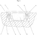
- the wall bracket according to the invention is generally identified in the figures with the reference number 1 and comprises a stationary part 2 and a removable part 3.
- the stationary part 2 comprises a socket (not shown in more detail) that can be inserted into a recess in a building wall and a metal plate 4.
- the metal plate is arranged below a receiving area 5 for an electronic device or for electronic components and protrudes over this area 5 on all sides.
- the removable part 3 has a cover plate 6, which consists of glass, covers the receiving area 5 and also protrudes over this on all sides.
- each side wall of the frame-shaped connecting part 7 there is a bore 8 which is perpendicular to the plane of the cover plate 6 and in which an axially displaceable holding magnet 9 is arranged, approximately halfway.
- the holding magnet is a permanent magnet.
- the bore 8 is round in cross section and the holding magnet 9 is cylindrical, so that although it is along the axis can be moved and rotated around the axis, but cannot be rotated off the axis.
- the reference numeral 10 denotes an assembly tool which is only shown schematically with the aid of a single release magnet 11.
- the assembly tool 10 also includes a plurality of release magnets 11 corresponding to the different holding magnets 9 in the removable part 3, as well as a handle.
- Figure 1 shows the holding device according to the invention in a closed position, the holding magnets 9 being at the end of the bores 8 on the mounting plate side.
- This position of the holding magnets 9 is essentially enforced by the magnetic attraction between the permanent magnetic holding elements 9 and the metallic iron or iron alloy plate 4. Due to the proximity of the holding magnets 9 to the mounting plate 4, the interaction between these two elements is relatively strong, which means that the removable part 3 (which is only fixed magnetically on the stationary part 2) can only be removed by overcoming a relatively large force, namely the force of attraction between the Holding magnets 9 and the mounting plate 4.
- the magnetic or magnetizable elements 4, 9 and 11 are designed so that the magnetic force of attraction between the release magnets 11 and holding magnets 9 is stronger than the magnetic force of attraction between holding magnets 9 and mounting plate 4, although initially there is an additional distance between holding magnets 9 and release magnets 11 due to the freedom of movement of holding magnets 9. Therefore pull the release magnets 11 of the assembly tool 10 Holding magnets 9 away from the mounting plate 4 and the holding magnets 9 move linearly within the bore 8 in the direction of the cover plate.
- the removal of the removable part 3 can serve, for example, to remove or insert an electronic device into the receiving area 5 or to access electronics arranged in the receiving area 5. It can also be used to lay and connect lines within the stationary part 2, on the electronic component or on the removable part 3.
- any other functional and display inserts can be located in the receiving area 5 below the cover plate 6, which e.g. include display and / or control electronics. It is particularly preferred, regardless of the device or the type of electronics, if the device or the electronics have an illuminated and touch-sensitive user interface (a touchscreen).
- the removable part 3 which adheres magnetically to the assembly tool 10
- the removable part 3 can be placed on the stationary part 2 and also pressed onto it by hand. It can then be removed by overcoming the magnetic force of attraction between the release magnet 11 and the holding magnet 9, while the removable part 3 is manually pressed against the stationary part 2.
- the holding magnets 9 within the bore 8 are again in the direction of the mounting plate 4 and thus in the in Figure 1 shown starting position pulled.
- FIG. 3 shows a further embodiment of a wall bracket 1 according to the invention in a closed position, with the embodiment according to FIG Figures 1 and 2 Corresponding components are provided with the same reference numerals.
- the stationary part 2 is designed in the form of a flush-mounted housing, which has several point-shaped assembly elements in the form of magnetizable metal and, for example, iron screws 4.
- the holding magnets 9 within the removable part 3 are arranged at positions within the connecting part 7 that correspond to the screws 4.
- the use of screws 4 as assembly elements has the advantage that the depth of the screw heads can be individually adjusted by turning the screws 4 in or out, which enables plaster compensation during assembly.
Landscapes
- Engineering & Computer Science (AREA)
- General Engineering & Computer Science (AREA)
- Mechanical Engineering (AREA)
- Casings For Electric Apparatus (AREA)
Claims (10)
- Support de paroi (1) pour un composant électronique avec une partie stationnaire (2), une partie pouvant être retirée (3), qui présente une plaque de recouvrement (6), et une zone de réception (5) située entre la partie stationnaire (2) et la plaque de recouvrement (6) pour le composant électronique, dans lequel la partie pouvant être retirée (3) repose de manière amovible sur la partie stationnaire (3) et la plaque de recouvrement (6) recouvre, dans l'état reposé, la zone de réception (5), caractérisé en ce que la partie pouvant être retirée (5) présente au moins un aimant de maintien (9) et la partie stationnaire (2) présente au moins un élément de montage (4) magnétique ou magnétisable pour attirer les aimants de maintien (9), dans lequel les aimants de maintien (9) sont montés de telle manière de manière mobile dans la partie pouvant être retirée (3) que leur distance par rapport aux éléments de montage (4) peut être modifiée, tandis que la partie pouvant être retirée (3) repose sur la partie stationnaire (2).
- Support de paroi selon la revendication 1, caractérisé en ce que les aimants de maintien (9) sont à aimantation permanente et les éléments de montage (4) peuvent être magnétisés.
- Support de paroi selon l'une quelconque des revendications précédentes, caractérisé en ce que la partie pouvant être retirée (3) comprend plusieurs aimants de maintien (9) répartis autour de la zone de réception (5).
- Support de paroi selon l'une quelconque des revendications précédentes, caractérisé en ce que la partie stationnaire (2) comprend un élément de montage plat (4), qui attire les aimants de maintien (9).
- Support de paroi selon l'une quelconque des revendications 1 à 3, caractérisé en ce que la partie stationnaire (2) comprend plusieurs éléments de montage (4) en forme de points pour respectivement un aimant de maintien (9), dans lequel les éléments de montage (4) et les aimants de maintien (9) sont disposés sur des positions correspondants.
- Support de paroi selon l'une quelconque des revendications précédentes, caractérisé en ce que la partie pouvant être retirée (3) comprend une partie de liaison (7), de préférence un cadre (7), qui est installé sur le côté intérieur de la plaque de recouvrement (6) et dans lequel les aimants de maintien (9) sont reçus.
- Support de paroi selon l'une quelconque des revendications précédentes, caractérisé en ce que les aimants de maintien (9) sont montés de telle sorte dans la partie pouvant être retirée qu'ils peuvent être déplacés en va-et-vient sur une trajectoire linéaire de manière normale par rapport au plan de la plaque de recouvrement (6).
- Support de paroi selon l'une quelconque des revendications précédentes, caractérisé en ce que la partie pouvant être retirée (3) et en particulier la partie de liaison (7) présentent des alésages (8), dans lesquels les aimants de maintien (9) sont reçus, dans lequel les alésages (8) s'étendent de préférence de manière linéaire et de manière normale par rapport au plan de la plaque de recouvrement (6) et dans lequel la section transversale des alésages (8) est de préférence ronde.
- Support de paroi selon l'une quelconque des revendications précédentes, caractérisé en ce que les aimants de maintien (9) sont des boutons magnétiques cylindriques circulaires, dont le diamètre correspond de préférence au diamètre intérieur des alésages (8).
- Procédé pour retirer la partie pouvant être retirée (3) de la partie stationnaire (2) d'un support de paroi (1) selon l'une quelconque des revendications précédentes,
caractérisé en ce
qu'un outil de montage (10), qui comprend au moins un aimant amovible (11), est approché de la plaque de recouvrement (6), dans lequel les aimants amovibles (11) agissent plus fortement sur les aimants de maintien (9) que les éléments de montage (4).
Applications Claiming Priority (1)
| Application Number | Priority Date | Filing Date | Title |
|---|---|---|---|
| DE102016002739.8A DE102016002739A1 (de) | 2016-03-08 | 2016-03-08 | Wandhalterung für elektronische Bauteile |
Publications (2)
| Publication Number | Publication Date |
|---|---|
| EP3216367A1 EP3216367A1 (fr) | 2017-09-13 |
| EP3216367B1 true EP3216367B1 (fr) | 2021-08-18 |
Family
ID=58227903
Family Applications (1)
| Application Number | Title | Priority Date | Filing Date |
|---|---|---|---|
| EP17157114.4A Active EP3216367B1 (fr) | 2016-03-08 | 2017-02-21 | Support de paroi pour composants électroniques |
Country Status (2)
| Country | Link |
|---|---|
| EP (1) | EP3216367B1 (fr) |
| DE (1) | DE102016002739A1 (fr) |
Families Citing this family (2)
| Publication number | Priority date | Publication date | Assignee | Title |
|---|---|---|---|---|
| DE102018101210B4 (de) | 2018-01-19 | 2019-08-22 | Fujitsu Client Computing Limited | Wandbefestigung für eine elektronische Anzeige, Computeranordnung und Verfahren zur Montage einer elektronischen Anzeige und eines Computersystems an einer Wand |
| DE202018001427U1 (de) | 2018-03-16 | 2019-06-18 | Controltronic Gmbh | Ein- und/oder Ausgabegerät mit hinterleuchteter Deckplatte |
Family Cites Families (4)
| Publication number | Priority date | Publication date | Assignee | Title |
|---|---|---|---|---|
| KR102043345B1 (ko) * | 2013-02-21 | 2019-11-11 | 엘지디스플레이 주식회사 | 디스플레이 장치의 벽면 고정 구조 |
| US8944826B1 (en) * | 2013-07-16 | 2015-02-03 | Curbell Medical Products, Inc. | Magnetic connection for cable assembly of electronic device |
| DE202015001146U1 (de) * | 2015-02-16 | 2015-03-09 | Daniel Thätner | Wandhaltesystem für mobile Endgeräte (Computer-Tablets & Smartphones) |
| DE202015006172U1 (de) * | 2015-09-01 | 2015-12-04 | Wan Chieh WU | Kombinierbare Mehrzweck-Wandhalterung zum Aufhängen von Gegenständen |
-
2016
- 2016-03-08 DE DE102016002739.8A patent/DE102016002739A1/de not_active Withdrawn
-
2017
- 2017-02-21 EP EP17157114.4A patent/EP3216367B1/fr active Active
Non-Patent Citations (1)
| Title |
|---|
| None * |
Also Published As
| Publication number | Publication date |
|---|---|
| EP3216367A1 (fr) | 2017-09-13 |
| DE102016002739A1 (de) | 2017-09-14 |
Similar Documents
| Publication | Publication Date | Title |
|---|---|---|
| EP2250334B1 (fr) | Dispositif pour immobiliser des portes par attraction magnétique | |
| EP3216367B1 (fr) | Support de paroi pour composants électroniques | |
| EP4201548A1 (fr) | Outil de poinçonnage | |
| DE10242467A1 (de) | Vorrichtung zur Unterbringung eines elektrischen Geräts im Innenraum eines Kraftfahrzeugs | |
| DE10261523A1 (de) | Vitrine zur Zurschaustellung von Gegenständen | |
| DE19530429C1 (de) | Hohlkörper für die Elektroinstallation | |
| DE202012012220U1 (de) | Frei positionierbarer Magnetgriff | |
| EP3661176A1 (fr) | Filtre de confidentialité magnétique | |
| DE202011004757U1 (de) | Zusätzlicher elektromechanischer Verschluss für Gehäuse, geeignet zur Unterbringung im Abkantungsraum von Blechschranktüren und Blechschrankrahmen und -Gehäusen | |
| EP3153642A1 (fr) | Systeme de montage pour eclairages | |
| DE202007016981U1 (de) | Befestigungsvorrichtung für ein elektrotechnisches Bauteil | |
| EP3344927B1 (fr) | Unité d'obturation conçue pour un passage d'air | |
| DE202011106151U1 (de) | Magnettafelanordnung zur Befestigung an einer Wand | |
| EP2905524A1 (fr) | Dispositif de maintien pour le maintien d'un appareil électronique sur un mur | |
| DE102010034339B4 (de) | Befestigungsset für elektronische Geräte | |
| DE3241407C1 (de) | Anzeige- und Bedientableau fuer Aufzugkabinen | |
| EP2634357B9 (fr) | Dispositif de protection contre les insectes et aide au positionnement pour son positionnement | |
| EP3020904B1 (fr) | Dispositif de recouvrement pour recouvrir une voie de roulement d'une installation de porte coulissante | |
| EP4453686A1 (fr) | Dispositif d'interface utilisateur monté magnétiquement, et kit associé | |
| EP2706634B1 (fr) | Appareil d'installation électrique/électronique doté d'un cadre de recouvrement | |
| EP4470868A1 (fr) | Véhicule ferroviaire comprenant un composant de véhicule et procédé de fixation | |
| DE202009004151U1 (de) | Tür- oder Hinweisschild sowie Einrichtung zur Diebstahlsicherung für ein solches Tür- oder Hinweisschild | |
| DE102009024470A1 (de) | Abdeckung mit innenliegender Fixierung | |
| EP1922454B1 (fr) | Systeme d'habillage a verrouillage et deverrouillage sans contact | |
| EP3879551A1 (fr) | Appareil de commutation électrique pour l'installation électrique de bâtiment et procédé correspondant |
Legal Events
| Date | Code | Title | Description |
|---|---|---|---|
| PUAI | Public reference made under article 153(3) epc to a published international application that has entered the european phase |
Free format text: ORIGINAL CODE: 0009012 |
|
| STAA | Information on the status of an ep patent application or granted ep patent |
Free format text: STATUS: THE APPLICATION HAS BEEN PUBLISHED |
|
| AK | Designated contracting states |
Kind code of ref document: A1 Designated state(s): AL AT BE BG CH CY CZ DE DK EE ES FI FR GB GR HR HU IE IS IT LI LT LU LV MC MK MT NL NO PL PT RO RS SE SI SK SM TR |
|
| AX | Request for extension of the european patent |
Extension state: BA ME |
|
| STAA | Information on the status of an ep patent application or granted ep patent |
Free format text: STATUS: REQUEST FOR EXAMINATION WAS MADE |
|
| 17P | Request for examination filed |
Effective date: 20180313 |
|
| RBV | Designated contracting states (corrected) |
Designated state(s): AL AT BE BG CH CY CZ DE DK EE ES FI FR GB GR HR HU IE IS IT LI LT LU LV MC MK MT NL NO PL PT RO RS SE SI SK SM TR |
|
| STAA | Information on the status of an ep patent application or granted ep patent |
Free format text: STATUS: EXAMINATION IS IN PROGRESS |
|
| 17Q | First examination report despatched |
Effective date: 20190710 |
|
| GRAP | Despatch of communication of intention to grant a patent |
Free format text: ORIGINAL CODE: EPIDOSNIGR1 |
|
| STAA | Information on the status of an ep patent application or granted ep patent |
Free format text: STATUS: GRANT OF PATENT IS INTENDED |
|
| INTG | Intention to grant announced |
Effective date: 20210303 |
|
| GRAS | Grant fee paid |
Free format text: ORIGINAL CODE: EPIDOSNIGR3 |
|
| GRAA | (expected) grant |
Free format text: ORIGINAL CODE: 0009210 |
|
| STAA | Information on the status of an ep patent application or granted ep patent |
Free format text: STATUS: THE PATENT HAS BEEN GRANTED |
|
| AK | Designated contracting states |
Kind code of ref document: B1 Designated state(s): AL AT BE BG CH CY CZ DE DK EE ES FI FR GB GR HR HU IE IS IT LI LT LU LV MC MK MT NL NO PL PT RO RS SE SI SK SM TR |
|
| REG | Reference to a national code |
Ref country code: GB Ref legal event code: FG4D Free format text: NOT ENGLISH |
|
| REG | Reference to a national code |
Ref country code: CH Ref legal event code: EP |
|
| REG | Reference to a national code |
Ref country code: DE Ref legal event code: R096 Ref document number: 502017011205 Country of ref document: DE |
|
| REG | Reference to a national code |
Ref country code: IE Ref legal event code: FG4D Free format text: LANGUAGE OF EP DOCUMENT: GERMAN Ref country code: AT Ref legal event code: REF Ref document number: 1420825 Country of ref document: AT Kind code of ref document: T Effective date: 20210915 |
|
| REG | Reference to a national code |
Ref country code: LT Ref legal event code: MG9D |
|
| REG | Reference to a national code |
Ref country code: NL Ref legal event code: MP Effective date: 20210818 |
|
| PG25 | Lapsed in a contracting state [announced via postgrant information from national office to epo] |
Ref country code: HR Free format text: LAPSE BECAUSE OF FAILURE TO SUBMIT A TRANSLATION OF THE DESCRIPTION OR TO PAY THE FEE WITHIN THE PRESCRIBED TIME-LIMIT Effective date: 20210818 Ref country code: ES Free format text: LAPSE BECAUSE OF FAILURE TO SUBMIT A TRANSLATION OF THE DESCRIPTION OR TO PAY THE FEE WITHIN THE PRESCRIBED TIME-LIMIT Effective date: 20210818 Ref country code: FI Free format text: LAPSE BECAUSE OF FAILURE TO SUBMIT A TRANSLATION OF THE DESCRIPTION OR TO PAY THE FEE WITHIN THE PRESCRIBED TIME-LIMIT Effective date: 20210818 Ref country code: PT Free format text: LAPSE BECAUSE OF FAILURE TO SUBMIT A TRANSLATION OF THE DESCRIPTION OR TO PAY THE FEE WITHIN THE PRESCRIBED TIME-LIMIT Effective date: 20211220 Ref country code: NO Free format text: LAPSE BECAUSE OF FAILURE TO SUBMIT A TRANSLATION OF THE DESCRIPTION OR TO PAY THE FEE WITHIN THE PRESCRIBED TIME-LIMIT Effective date: 20211118 Ref country code: LT Free format text: LAPSE BECAUSE OF FAILURE TO SUBMIT A TRANSLATION OF THE DESCRIPTION OR TO PAY THE FEE WITHIN THE PRESCRIBED TIME-LIMIT Effective date: 20210818 Ref country code: BG Free format text: LAPSE BECAUSE OF FAILURE TO SUBMIT A TRANSLATION OF THE DESCRIPTION OR TO PAY THE FEE WITHIN THE PRESCRIBED TIME-LIMIT Effective date: 20211118 Ref country code: SE Free format text: LAPSE BECAUSE OF FAILURE TO SUBMIT A TRANSLATION OF THE DESCRIPTION OR TO PAY THE FEE WITHIN THE PRESCRIBED TIME-LIMIT Effective date: 20210818 Ref country code: RS Free format text: LAPSE BECAUSE OF FAILURE TO SUBMIT A TRANSLATION OF THE DESCRIPTION OR TO PAY THE FEE WITHIN THE PRESCRIBED TIME-LIMIT Effective date: 20210818 |
|
| PG25 | Lapsed in a contracting state [announced via postgrant information from national office to epo] |
Ref country code: PL Free format text: LAPSE BECAUSE OF FAILURE TO SUBMIT A TRANSLATION OF THE DESCRIPTION OR TO PAY THE FEE WITHIN THE PRESCRIBED TIME-LIMIT Effective date: 20210818 Ref country code: LV Free format text: LAPSE BECAUSE OF FAILURE TO SUBMIT A TRANSLATION OF THE DESCRIPTION OR TO PAY THE FEE WITHIN THE PRESCRIBED TIME-LIMIT Effective date: 20210818 Ref country code: GR Free format text: LAPSE BECAUSE OF FAILURE TO SUBMIT A TRANSLATION OF THE DESCRIPTION OR TO PAY THE FEE WITHIN THE PRESCRIBED TIME-LIMIT Effective date: 20211119 |
|
| PG25 | Lapsed in a contracting state [announced via postgrant information from national office to epo] |
Ref country code: NL Free format text: LAPSE BECAUSE OF FAILURE TO SUBMIT A TRANSLATION OF THE DESCRIPTION OR TO PAY THE FEE WITHIN THE PRESCRIBED TIME-LIMIT Effective date: 20210818 |
|
| PG25 | Lapsed in a contracting state [announced via postgrant information from national office to epo] |
Ref country code: DK Free format text: LAPSE BECAUSE OF FAILURE TO SUBMIT A TRANSLATION OF THE DESCRIPTION OR TO PAY THE FEE WITHIN THE PRESCRIBED TIME-LIMIT Effective date: 20210818 |
|
| REG | Reference to a national code |
Ref country code: DE Ref legal event code: R097 Ref document number: 502017011205 Country of ref document: DE |
|
| PG25 | Lapsed in a contracting state [announced via postgrant information from national office to epo] |
Ref country code: SM Free format text: LAPSE BECAUSE OF FAILURE TO SUBMIT A TRANSLATION OF THE DESCRIPTION OR TO PAY THE FEE WITHIN THE PRESCRIBED TIME-LIMIT Effective date: 20210818 Ref country code: SK Free format text: LAPSE BECAUSE OF FAILURE TO SUBMIT A TRANSLATION OF THE DESCRIPTION OR TO PAY THE FEE WITHIN THE PRESCRIBED TIME-LIMIT Effective date: 20210818 Ref country code: RO Free format text: LAPSE BECAUSE OF FAILURE TO SUBMIT A TRANSLATION OF THE DESCRIPTION OR TO PAY THE FEE WITHIN THE PRESCRIBED TIME-LIMIT Effective date: 20210818 Ref country code: EE Free format text: LAPSE BECAUSE OF FAILURE TO SUBMIT A TRANSLATION OF THE DESCRIPTION OR TO PAY THE FEE WITHIN THE PRESCRIBED TIME-LIMIT Effective date: 20210818 Ref country code: CZ Free format text: LAPSE BECAUSE OF FAILURE TO SUBMIT A TRANSLATION OF THE DESCRIPTION OR TO PAY THE FEE WITHIN THE PRESCRIBED TIME-LIMIT Effective date: 20210818 Ref country code: AL Free format text: LAPSE BECAUSE OF FAILURE TO SUBMIT A TRANSLATION OF THE DESCRIPTION OR TO PAY THE FEE WITHIN THE PRESCRIBED TIME-LIMIT Effective date: 20210818 |
|
| PLBE | No opposition filed within time limit |
Free format text: ORIGINAL CODE: 0009261 |
|
| STAA | Information on the status of an ep patent application or granted ep patent |
Free format text: STATUS: NO OPPOSITION FILED WITHIN TIME LIMIT |
|
| 26N | No opposition filed |
Effective date: 20220519 |
|
| PG25 | Lapsed in a contracting state [announced via postgrant information from national office to epo] |
Ref country code: IT Free format text: LAPSE BECAUSE OF FAILURE TO SUBMIT A TRANSLATION OF THE DESCRIPTION OR TO PAY THE FEE WITHIN THE PRESCRIBED TIME-LIMIT Effective date: 20210818 |
|
| PG25 | Lapsed in a contracting state [announced via postgrant information from national office to epo] |
Ref country code: SI Free format text: LAPSE BECAUSE OF FAILURE TO SUBMIT A TRANSLATION OF THE DESCRIPTION OR TO PAY THE FEE WITHIN THE PRESCRIBED TIME-LIMIT Effective date: 20210818 |
|
| PG25 | Lapsed in a contracting state [announced via postgrant information from national office to epo] |
Ref country code: MC Free format text: LAPSE BECAUSE OF FAILURE TO SUBMIT A TRANSLATION OF THE DESCRIPTION OR TO PAY THE FEE WITHIN THE PRESCRIBED TIME-LIMIT Effective date: 20210818 |
|
| REG | Reference to a national code |
Ref country code: CH Ref legal event code: PL |
|
| REG | Reference to a national code |
Ref country code: BE Ref legal event code: MM Effective date: 20220228 |
|
| GBPC | Gb: european patent ceased through non-payment of renewal fee |
Effective date: 20220221 |
|
| PG25 | Lapsed in a contracting state [announced via postgrant information from national office to epo] |
Ref country code: LU Free format text: LAPSE BECAUSE OF NON-PAYMENT OF DUE FEES Effective date: 20220221 |
|
| PG25 | Lapsed in a contracting state [announced via postgrant information from national office to epo] |
Ref country code: FR Free format text: LAPSE BECAUSE OF NON-PAYMENT OF DUE FEES Effective date: 20220228 |
|
| PG25 | Lapsed in a contracting state [announced via postgrant information from national office to epo] |
Ref country code: LI Free format text: LAPSE BECAUSE OF NON-PAYMENT OF DUE FEES Effective date: 20220228 Ref country code: IE Free format text: LAPSE BECAUSE OF NON-PAYMENT OF DUE FEES Effective date: 20220221 Ref country code: GB Free format text: LAPSE BECAUSE OF NON-PAYMENT OF DUE FEES Effective date: 20220221 Ref country code: CH Free format text: LAPSE BECAUSE OF NON-PAYMENT OF DUE FEES Effective date: 20220228 |
|
| PG25 | Lapsed in a contracting state [announced via postgrant information from national office to epo] |
Ref country code: BE Free format text: LAPSE BECAUSE OF NON-PAYMENT OF DUE FEES Effective date: 20220228 |
|
| REG | Reference to a national code |
Ref country code: AT Ref legal event code: MM01 Ref document number: 1420825 Country of ref document: AT Kind code of ref document: T Effective date: 20220221 |
|
| PG25 | Lapsed in a contracting state [announced via postgrant information from national office to epo] |
Ref country code: AT Free format text: LAPSE BECAUSE OF NON-PAYMENT OF DUE FEES Effective date: 20220221 |
|
| PG25 | Lapsed in a contracting state [announced via postgrant information from national office to epo] |
Ref country code: HU Free format text: LAPSE BECAUSE OF FAILURE TO SUBMIT A TRANSLATION OF THE DESCRIPTION OR TO PAY THE FEE WITHIN THE PRESCRIBED TIME-LIMIT; INVALID AB INITIO Effective date: 20170221 |
|
| PG25 | Lapsed in a contracting state [announced via postgrant information from national office to epo] |
Ref country code: MK Free format text: LAPSE BECAUSE OF FAILURE TO SUBMIT A TRANSLATION OF THE DESCRIPTION OR TO PAY THE FEE WITHIN THE PRESCRIBED TIME-LIMIT Effective date: 20210818 Ref country code: CY Free format text: LAPSE BECAUSE OF FAILURE TO SUBMIT A TRANSLATION OF THE DESCRIPTION OR TO PAY THE FEE WITHIN THE PRESCRIBED TIME-LIMIT Effective date: 20210818 |
|
| PG25 | Lapsed in a contracting state [announced via postgrant information from national office to epo] |
Ref country code: MT Free format text: LAPSE BECAUSE OF FAILURE TO SUBMIT A TRANSLATION OF THE DESCRIPTION OR TO PAY THE FEE WITHIN THE PRESCRIBED TIME-LIMIT Effective date: 20210818 |
|
| PG25 | Lapsed in a contracting state [announced via postgrant information from national office to epo] |
Ref country code: TR Free format text: LAPSE BECAUSE OF FAILURE TO SUBMIT A TRANSLATION OF THE DESCRIPTION OR TO PAY THE FEE WITHIN THE PRESCRIBED TIME-LIMIT Effective date: 20210818 |
|
| PGFP | Annual fee paid to national office [announced via postgrant information from national office to epo] |
Ref country code: DE Payment date: 20260226 Year of fee payment: 10 |