EP3216509A1 - Filter und ölfänger - Google Patents
Filter und ölfänger Download PDFInfo
- Publication number
- EP3216509A1 EP3216509A1 EP15856993.9A EP15856993A EP3216509A1 EP 3216509 A1 EP3216509 A1 EP 3216509A1 EP 15856993 A EP15856993 A EP 15856993A EP 3216509 A1 EP3216509 A1 EP 3216509A1
- Authority
- EP
- European Patent Office
- Prior art keywords
- main
- filter
- filter unit
- main filter
- unit
- Prior art date
- Legal status (The legal status is an assumption and is not a legal conclusion. Google has not performed a legal analysis and makes no representation as to the accuracy of the status listed.)
- Withdrawn
Links
Images




Classifications
-
- B—PERFORMING OPERATIONS; TRANSPORTING
- B60—VEHICLES IN GENERAL
- B60T—VEHICLE BRAKE CONTROL SYSTEMS OR PARTS THEREOF; BRAKE CONTROL SYSTEMS OR PARTS THEREOF, IN GENERAL; ARRANGEMENT OF BRAKING ELEMENTS ON VEHICLES IN GENERAL; PORTABLE DEVICES FOR PREVENTING UNWANTED MOVEMENT OF VEHICLES; VEHICLE MODIFICATIONS TO FACILITATE COOLING OF BRAKES
- B60T17/00—Component parts, details, or accessories of power brake systems not covered by groups B60T8/00, B60T13/00 or B60T15/00, or presenting other characteristic features
- B60T17/002—Air treatment devices
- B60T17/004—Draining and drying devices
-
- B—PERFORMING OPERATIONS; TRANSPORTING
- B60—VEHICLES IN GENERAL
- B60T—VEHICLE BRAKE CONTROL SYSTEMS OR PARTS THEREOF; BRAKE CONTROL SYSTEMS OR PARTS THEREOF, IN GENERAL; ARRANGEMENT OF BRAKING ELEMENTS ON VEHICLES IN GENERAL; PORTABLE DEVICES FOR PREVENTING UNWANTED MOVEMENT OF VEHICLES; VEHICLE MODIFICATIONS TO FACILITATE COOLING OF BRAKES
- B60T17/00—Component parts, details, or accessories of power brake systems not covered by groups B60T8/00, B60T13/00 or B60T15/00, or presenting other characteristic features
- B60T17/002—Air treatment devices
-
- B—PERFORMING OPERATIONS; TRANSPORTING
- B01—PHYSICAL OR CHEMICAL PROCESSES OR APPARATUS IN GENERAL
- B01D—SEPARATION
- B01D39/00—Filtering material for liquid or gaseous fluids
- B01D39/08—Filter cloth, i.e. woven, knitted or interlaced material
-
- B—PERFORMING OPERATIONS; TRANSPORTING
- B01—PHYSICAL OR CHEMICAL PROCESSES OR APPARATUS IN GENERAL
- B01D—SEPARATION
- B01D39/00—Filtering material for liquid or gaseous fluids
- B01D39/08—Filter cloth, i.e. woven, knitted or interlaced material
- B01D39/083—Filter cloth, i.e. woven, knitted or interlaced material of organic material
-
- B—PERFORMING OPERATIONS; TRANSPORTING
- B01—PHYSICAL OR CHEMICAL PROCESSES OR APPARATUS IN GENERAL
- B01D—SEPARATION
- B01D39/00—Filtering material for liquid or gaseous fluids
- B01D39/14—Other self-supporting filtering material ; Other filtering material
- B01D39/16—Other self-supporting filtering material ; Other filtering material of organic material, e.g. synthetic fibres
- B01D39/1607—Other self-supporting filtering material ; Other filtering material of organic material, e.g. synthetic fibres the material being fibrous
- B01D39/1623—Other self-supporting filtering material ; Other filtering material of organic material, e.g. synthetic fibres the material being fibrous of synthetic origin
-
- B—PERFORMING OPERATIONS; TRANSPORTING
- B01—PHYSICAL OR CHEMICAL PROCESSES OR APPARATUS IN GENERAL
- B01D—SEPARATION
- B01D39/00—Filtering material for liquid or gaseous fluids
- B01D39/14—Other self-supporting filtering material ; Other filtering material
- B01D39/20—Other self-supporting filtering material ; Other filtering material of inorganic material, e.g. asbestos paper, metallic filtering material of non-woven wires
- B01D39/2027—Metallic material
- B01D39/2041—Metallic material the material being filamentary or fibrous
-
- B—PERFORMING OPERATIONS; TRANSPORTING
- B01—PHYSICAL OR CHEMICAL PROCESSES OR APPARATUS IN GENERAL
- B01D—SEPARATION
- B01D46/00—Filters or filtering processes specially modified for separating dispersed particles from gases or vapours
- B01D46/0027—Filters or filtering processes specially modified for separating dispersed particles from gases or vapours with additional separating or treating functions
- B01D46/003—Filters or filtering processes specially modified for separating dispersed particles from gases or vapours with additional separating or treating functions including coalescing means for the separation of liquid
- B01D46/0031—Filters or filtering processes specially modified for separating dispersed particles from gases or vapours with additional separating or treating functions including coalescing means for the separation of liquid with collecting, draining means
-
- B—PERFORMING OPERATIONS; TRANSPORTING
- B01—PHYSICAL OR CHEMICAL PROCESSES OR APPARATUS IN GENERAL
- B01D—SEPARATION
- B01D46/00—Filters or filtering processes specially modified for separating dispersed particles from gases or vapours
- B01D46/24—Particle separators, e.g. dust precipitators, using rigid hollow filter bodies
-
- B—PERFORMING OPERATIONS; TRANSPORTING
- B01—PHYSICAL OR CHEMICAL PROCESSES OR APPARATUS IN GENERAL
- B01D—SEPARATION
- B01D53/00—Separation of gases or vapours; Recovering vapours of volatile solvents from gases; Chemical or biological purification of waste gases, e.g. engine exhaust gases, smoke, fumes, flue gases, aerosols
- B01D53/26—Drying gases or vapours
- B01D53/266—Drying gases or vapours by filtration
-
- F—MECHANICAL ENGINEERING; LIGHTING; HEATING; WEAPONS; BLASTING
- F24—HEATING; RANGES; VENTILATING
- F24F—AIR-CONDITIONING; AIR-HUMIDIFICATION; VENTILATION; USE OF AIR CURRENTS FOR SCREENING
- F24F13/00—Details common to, or for air-conditioning, air-humidification, ventilation or use of air currents for screening
- F24F13/02—Ducting arrangements
-
- B—PERFORMING OPERATIONS; TRANSPORTING
- B01—PHYSICAL OR CHEMICAL PROCESSES OR APPARATUS IN GENERAL
- B01D—SEPARATION
- B01D2239/00—Aspects relating to filtering material for liquid or gaseous fluids
- B01D2239/06—Filter cloth, e.g. knitted, woven non-woven; self-supported material
- B01D2239/0604—Arrangement of the fibres in the filtering material
- B01D2239/0636—Two or more types of fibres present in the filter material
-
- B—PERFORMING OPERATIONS; TRANSPORTING
- B01—PHYSICAL OR CHEMICAL PROCESSES OR APPARATUS IN GENERAL
- B01D—SEPARATION
- B01D2239/00—Aspects relating to filtering material for liquid or gaseous fluids
- B01D2239/06—Filter cloth, e.g. knitted, woven non-woven; self-supported material
- B01D2239/069—Special geometry of layers
- B01D2239/0695—Wound layers
-
- B—PERFORMING OPERATIONS; TRANSPORTING
- B01—PHYSICAL OR CHEMICAL PROCESSES OR APPARATUS IN GENERAL
- B01D—SEPARATION
- B01D2258/00—Sources of waste gases
- B01D2258/02—Other waste gases
- B01D2258/0283—Flue gases
-
- B—PERFORMING OPERATIONS; TRANSPORTING
- B01—PHYSICAL OR CHEMICAL PROCESSES OR APPARATUS IN GENERAL
- B01D—SEPARATION
- B01D2259/00—Type of treatment
- B01D2259/45—Gas separation or purification devices adapted for specific applications
- B01D2259/4566—Gas separation or purification devices adapted for specific applications for use in transportation means
-
- B—PERFORMING OPERATIONS; TRANSPORTING
- B01—PHYSICAL OR CHEMICAL PROCESSES OR APPARATUS IN GENERAL
- B01D—SEPARATION
- B01D2275/00—Filter media structures for filters specially adapted for separating dispersed particles from gases or vapours
- B01D2275/10—Multiple layers
- B01D2275/105—Wound layers
-
- B—PERFORMING OPERATIONS; TRANSPORTING
- B01—PHYSICAL OR CHEMICAL PROCESSES OR APPARATUS IN GENERAL
- B01D—SEPARATION
- B01D46/00—Filters or filtering processes specially modified for separating dispersed particles from gases or vapours
- B01D46/42—Auxiliary equipment or operation thereof
- B01D46/4236—Reducing noise or vibration emissions
Definitions
- the present invention relates to a technical field relating to a filter and an oil catch apparatus disposed in piping for air passage and separating water, oil, impurities, and the like mixed in the air.
- the compressed air may contain oil for lubricating the inside of the compressor. If the oil enters the system, malfunction may occur.
- Patent Document 1 JP 2013-174224A
- the oil catch apparatus described in Patent Document 1 has a structure that separates the oil and recovers the same by making air containing the oil collide with a collision plate. Thus, it is necessary to ensure a distance for making the air collide with the collision plate, resulting in an increase in the apparatus size.
- the present invention has been made in view of the above situation, and an object thereof is to provide an oil catch apparatus capable of extracting a sufficient amount of oil albeit being of compact size.
- a filter according to an embodiment of the present invention includes: a cylindrically formed main filter unit; a first keep member for keeping one end of the main filter unit; and a second keep member for keeping the other end of the main filter unit. Air flowing into the main filter unit from an opening formed in the first keep member is cleared of impurities upon passing through the main filter unit, and exits from a peripheral surface of the main filter unit.
- the main filter unit includes an element formed of a metallic network sheet and a resinous mesh sheet.
- the element is formed by winding a stack of a stainless network sheet and a resinous mesh sheet cylindrically.
- the main filter unit includes: an outer cylindrical member comprising a sheet-form stainless material having an opening formed therein, and an inner cylindrical member located inside of the outer cylindrical member with the element held between them and comprising a sheet-form stainless material having an opening formed therein.
- the filter according to the embodiment of the present invention further includes an inlet member inserted into the opening formed in the first keep member.
- the filter according to the embodiment of the present invention further includes a muffler inside of the main filter unit.
- the muffler includes a muffler member that is located on the first keep member side inside of the main filter unit and vertically with respect to an axial direction.
- the muffler member includes a surface member and a back-surface member, each formed of a mesh sheet, and a coupler member that makes a coupling between the surface member and the back-surface member.
- an oil catch apparatus includes: a main unit; a lid that covers up an opening in the main unit; a filter according to any one of claims 1 to 8 that is located inside of the main unit; and a buffer that supports the filter.
- a filter according to an embodiment of the present invention includes: a cylindrically formed main filter unit; a first keep member for keeping one end of the main filter unit; and a second keep member for keeping the other end of the main filter unit. Air flowing into the main filter unit from an opening formed in the first keep member is cleared of impurities upon passing through the main filter unit, and exits from a peripheral surface of the main filter unit. Thus, the filter can extract a sufficient amount of oil albeit being of compact size.
- the main filter unit includes an element formed of a metallic network sheet and a resinous mesh sheet, thereby allowing the oil and the like to be separated and collected efficiently within a limited space.
- the element is formed by winding a stack of a stainless network sheet and a resinous mesh sheet cylindrically, thereby allowing the filter 1 to be manufactured at low cost.
- the main filter unit includes: an outer cylindrical member comprising a sheet-form stainless material having an opening formed therein, and an inner cylindrical member located inside of the outer cylindrical member with the element held between them and comprising a sheet-form stainless material having an opening formed therein.
- the filter according to the embodiment of the present invention further includes an inlet member inserted into the opening formed in the first keep member can thus be attached to an air flow path with ease.
- the filter according to the embodiment of the present invention further includes a muffler inside of the main filter unit, thereby allowing muffling effect to be enhanced.
- the muffler includes a muffler member that is located on the first keep member side inside of the main filter unit and vertically with respect to an axial direction.
- the muffler member includes a surface member and a back-surface member, each formed of a mesh sheet, and a coupler member that makes a coupling between the surface member and the back-surface member.
- an oil catch apparatus includes: a main unit; a lid that covers up an opening in the main unit; a filter according to any one of claims 1 to 8 that is located inside of the main unit; and a buffer that supports the filter.
- the oil catch apparatus 100 can extract a sufficient amount of oil albeit being of compact size.
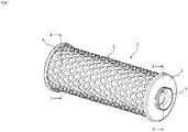
- FIG. 1 is a perspective view of an oil filter according to an embodiment of the present invention.
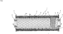
- FIG. 2 is a cross-sectional view as viewed in the direction of the arrow II-II of FIG. 1 .
- a filter 1 includes a main filter unit 2, a first keep member 3, a second keep member 4, an inlet member 5, a mounting member 6, and a muffler 7.
- One end of the main filter unit 2 is held by the first keep member 3, and the other end thereof is held by the second keep member 4.
- the inlet member 5 is attached to the first keep member 3, and the mounting member 6 is attached to the second keep member 4.
- the muffler 7 is attached to the inner periphery of the main filter unit 2 at the side of the inlet member 5.
- the main filter unit 2 has an outer cylindrical member 21, an inner cylindrical member 22, and an element 23.
- the outer cylindrical member 21 is formed by winding, in a tubular shape, sheet-form stainless having openings 21a formed therein.
- the inner cylindrical member 22 is formed by winding sheet-form stainless having openings 22a in a tubular shape and is located inside the outer cylindrical member 21.
- the element 23 is formed by winding a stack of a predetermined number of stainless network sheets and a predetermined number of resinous mesh sheets cylindrically and incorporated between the outer cylindrical member 21 and inner cylindrical member 22.
- the above material and structure of the element 23 are illustrative and may be arbitrarily selected considering separation efficiency or resistance.
- the first keep member 3 and second keep member 4 keep the both ends of the cylindrically-formed main filter unit 2, respectively to thereby keep the winding state of the main filter unit 2.
- a first insertion opening 3a is formed at the center of the first keep member 3, and the inlet member 5 is inserted thereinto.
- a second insertion opening 4a is formed at the center of the second keep member 4, and the mounting member 6 is inserted thereinto.
- a not illustrated flow path for inflow of air containing impurities such as oil is inserted into the inlet member 5.
- a filter support member to be described later is inserted into the mounting member 6.
- a configuration may be possible in which second insertion opening 4a and mounting member 6 are not provided, but the second keep member 4 is directly supported by another member.
- the first and second keep members 3 and 4 may be made of the same material, and the inlet member 5 and mounting member 6 may be made of the same material, whereby manufacturing cost can be reduced.
- the muffler 7 has a muffler member 71, a first support member 72, and a second support member 73.
- the first and second support members 72 and 73 are attached to the inner periphery of the main filter unit 2 at the side of the inlet member 5 with a predetermined interval therebetween.
- the muffler member 71 is incorporated between the first and second support members 72 and 73.
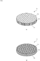
- FIGS. 3A and 3B are perspective views each illustrating an example of the muffler member according the present embodiment.
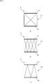
- FIGS. 4A and 4B each illustrate an example of a mesh structure of a surface member or a back-surface member.
- FIGS. 5A to 5C each illustrate an example of a coupling structure of a coupler member.
- FIGS. 6A and 6B each illustrate an example of the first support member or second support member.
- the muffler member 71 has a surface member 71a, a back-surface member 71b, and a coupler member 71c.
- the surface member 71a and back-surface member 71b are each a sheet formed in a mesh by use of polyethylene terephthalate, synthetic resin, or chemical fiber.
- the surface member 71a and back-surface member 71b are formed into a circular shape having substantially the same diameter as the inner periphery of the inner cylindrical member 22.
- the mesh structure of each of the surface member 71a and back-surface member 71b may not only be the mesh patterns illustrated in FIGS. 3A and 3B , but also the hexagonal pattern as illustrated in FIG. 4A or the plain weave pattern as illustrated in FIG. 4B . Using the thus configured surface member 71a and back-surface member 71b allows extensibility and surface rigidity to be improved.
- the coupler member 71c is formed in a fiber shape by use of polyethylene terephthalate, synthetic resin, or chemical fiber and makes a coupling between the surface member 71a and back-surface member 71b.
- the coupler member 71c may have not only the coupling structures illustrated in FIGS. 3A and 3B , but also the bracing structure as illustrated in FIG. 5A , the cross structure as illustrated in FIG. 5B , or the truss structure as illustrated in FIG. 5C . Using the thus configured coupler member 71c allows strength at compression to be improved.
- the first and second support members 72 and 73 support the muffler member 71 by sandwiching the same from both sides.
- the first and second support members 72 and 73 are each formed into a circular shape having substantially the same diameter as the inner periphery of the inner cylindrical member 22 and attached to the inner periphery of the inner cylindrical member 22.
- the first and second support members 72 and 73 have openings 72a and 73a, respectively, at a position including at least the center thereof.
- the shapes of the openings 72a and 73a may each be the circular shape as illustrated in FIG. 6A .
- the first and second support members 72 and 73 may each have a support part for supporting the muffler member 71 inside the circular shape.
- the thus configured filter 1 allows the oil and the like to be separated and collected efficiently within a limited space. Further, using the stainless material allows the filter 1 to be manufactured at lower cost than with a conventional filter made of brass. Further, using the mesh structure element 23 can enhance muffling effect. In addition, incorporating the muffler 7 can further enhance muffling effect. Furthermore, the axis of the main filter unit 2 of the filter 1 can be set in the horizontal direction, so that effective utilization of space and space-saving arrangement can be achieved.
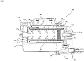
- FIG. 7 is a cross-sectional view of the oil catch apparatus 100 according to the present embodiment.
- FIG. 8 is a side view of the oil catch apparatus 100 according to the present embodiment.
- the oil catch apparatus 100 includes a main unit 120, a lid 130 that covers the opening of the main unit 120, a hose 140 attached to the lid 130, an exhaust guide 150 that guides flow of exhaust air, and a mounting part 160 installed in the main unit 120.
- the main unit 120 has a cylinder 121, a bottom part 122, and a main unit flange 123.
- the cylinder 121 according to the present embodiment is disposed such that the axis thereof is set in the horizontal direction.
- the cylinder 121 is formed into a cylindrical shape, it may have a rectangular cylindrical shape or an elliptic cylindrical shape.
- the bottom part 122 is formed so as to close one opening of the cylinder 121.
- An exhaust opening 121a is formed on the bottom part 122 side of the cylinder 121.
- the main unit flange 123 protrudes outward from the cylinder 121 at a side opposite to the bottom part 122 in a direction perpendicular to the longitudinal direction of the main unit 120.
- the cylinder 121, bottom part 122, and flange part 123 may be formed separately and joined together by welding or the like, they are preferably formed integrally.
- the lid 130 has a flat part 131, a side part 132, and a lid flange 133.
- the shape of the flat part 131 is preferably the same as that of the bottom part 122 of the main unit 120.
- An inlet 131a protrudes from the flat surface of the flat part 131 and has therein a hole penetrating therethrough in the same direction as the protruding direction thereof.
- the inlet 131a preferably protrudes in a direction perpendicular to the flat surface.
- the side part 132 extends in the vertical direction from the outer periphery of the flat part 131.
- the side part 132 has first and second protruding parts 132a and 132b protruding the side thereof.
- a drain outlet 131b protrudes from the flat surface of the side part 132 and has therein a hole penetrating therethrough in the same direction as the protruding direction thereof.
- a stop 131c protrudes from the flat surface of the second protruding part 132b.
- the first and second protruding parts 132a and 132b preferably protrude in a direction perpendicular to the side surface.
- the lid flange 133 protrudes outward from the side part 132 at a side opposite to the flat part 131 in a direction perpendicular to the longitudinal direction of the main unit 120.
- Coupling holes 123a and 133a through each of which a bolt B for coupling the main unit 120 and lid 130 penetrates are formed in the main unit flange 123 and lid flange 133, respectively.
- the bolt B penetrating through each of the coupling holes 123a and 133a is fastened by a nut N.
- the bolt B and nut N are used as a coupling part for coupling the main unit 120 and lid 130 in the present embodiment, another structure may be used.
- the hose 140 has a tubular member 141 made of a transparent or translucent soft material.
- One side of the tubular member 141 is coupled by a first clip 142 or the like to an amount detecting port 131d separated from the drain outlet 131b in the first protruding part 132a of the lid 130.
- the other side of the tubular member 141 is normally attached to the stop 131c of the lid 130 by a second clip 143 or the like.
- the exhaust guide 150 is installed to the cylinder 121 so as to cover the exhaust opening 121a formed in the upper portion of the cylinder 121 of the main unit 120 with its eaves.
- the exhaust guide 150 guides exhaust gas exhausted from the exhaust opening 121a.
- the mounting part 160 is installed to the cylinder 121 of the main unit 120.
- the main unit 120 is mounted to a not illustrated vehicle body through the mounting part 160.
- a buffer 180 has a filter support member 181, a buffer member 182, and a buffer mounting member 183.
- the filter support member 181 supports the second keep member 4 through the mounting member 6 and mounted to the main unit 120 together with the buffer member 182 and buffer mounting member 183.
- the buffer member 182 is formed into a tubular shape so as to cover a portion of the filter 1 on the side opposite to the inlet 131a.
- a third insertion opening 182a into which the filter support member 181 is inserted is formed at the center of the buffer member 182.
- the buffer mounting member 183 is supported by the filter support member 181 at one end thereof and supported by the lid 130 at the other end thereof.
- the buffer 180 By installing the buffer 180, it is possible to suppress the oil and the like separated from air from splashing.
- Air flowing in the oil catch apparatus 100 from the inlet 131a flows inside the filter 1 is cleared of the oil and the like upon passing through the filter 1.
- the air on the outer peripheral side of the filter 1 is in a purified state where the oil and the like have been separated.
- the purified air is exhausted from the exhaust opening 121a.
- the oil and the like separated in the filter 1 fall downward to be accumulated temporarily in the cylinder 121 of the main unit 120. Thereafter, the oil and the like are discharged from the drain outlet 131b.
- FIG. 9 illustrates an air treatment system 200 using the oil catch apparatus 100 according to the present embodiment.
- the air treatment system 200 controls a braking system or the like using compressed air fed from a compressor 201.
- the compressed air exhausted from the compressor 201 is fed to an air dryer 202.
- the air dryer 202 removes the oil and the like contained in the compressed air and feds the resultant dry air to an air tank 203.
- Direct disposal of the oil and the like removed by the air dryer 202 can greatly affect environment, so that the oil and the like are separated and collected by the oil catch apparatus 100 according to the present embodiment.
- the filter 1 includes the cylindrically-formed main filter unit 2, first keep member 3 that keeps the both ends of the main filter unit 2, and second keep member 4 that keeps the other end of the main filter unit 2. Air flowing inside the main filter unit 2 through the opening 3a formed in the first keep member 3 is cleared of the oil and the like upon passing through the main filter unit 2 and exits from the outer peripheral side of the main filter unit 2. Thus, the filter 1 can extract a sufficient amount of oil albeit being of compact size.
- the main filter unit 2 has the element 23 formed by use of metallic network sheets and resinous mesh sheets, thereby allowing the oil and the like to be separated and collected efficiently within a limited space.
- the element 23 is formed by winding a stack of stainless network sheets and resinous mesh sheets cylindrically, thereby allowing the filter 1 to be manufactured at low cost.
- the main filter unit 2 has the outer cylindrical member 21 made of sheet-form stainless having openings formed therein, inner cylindrical member 22 made of sheet-form stainless having openings formed therein and located inside the outer cylindrical member 21 with the element 23 interposed therebetween.
- the filter 1 according to the present embodiment has the inlet member 5 inserted into the opening 3a formed in the first keep member 3 and can thus be attached to an air flow path with ease.
- the filter 1 according to the present embodiment has the muffler 7 inside the main filter unit 2, thereby allowing muffling effect to be enhanced.
- the muffler 7 has the muffler member 71 located on the first keep member 3 side inside of the main filter unit 2 and vertically with respect to the axial direction of the filter 1.
- the muffler member 71 has the surface member 71a and back-surface member 71b which are each made of a mesh sheet and coupler member 71c that makes a coupling between the surface member 71a and back-surface member 71b.
- the surface member 71a and back-surface member 71b which are each made of a mesh sheet and coupler member 71c that makes a coupling between the surface member 71a and back-surface member 71b.
- the oil catch apparatus 100 includes the main unit 120, lid 130 that covers the opening of the main unit 120, filter 1 located inside the main unit 120, and buffer 180 that supports the filter 1.
- the oil catch apparatus 100 can extract a sufficient amount of oil albeit being of compact size.
Landscapes
- Engineering & Computer Science (AREA)
- Chemical & Material Sciences (AREA)
- Chemical Kinetics & Catalysis (AREA)
- Mechanical Engineering (AREA)
- Transportation (AREA)
- Textile Engineering (AREA)
- General Engineering & Computer Science (AREA)
- Combustion & Propulsion (AREA)
- Life Sciences & Earth Sciences (AREA)
- Geology (AREA)
- Oil, Petroleum & Natural Gas (AREA)
- General Chemical & Material Sciences (AREA)
- Analytical Chemistry (AREA)
- Filtering Of Dispersed Particles In Gases (AREA)
- Duct Arrangements (AREA)
- Filtering Materials (AREA)
Applications Claiming Priority (2)
| Application Number | Priority Date | Filing Date | Title |
|---|---|---|---|
| JP2014226103A JP2016087557A (ja) | 2014-11-06 | 2014-11-06 | フィルタ及びオイルキャッチ装置 |
| PCT/JP2015/077961 WO2016072184A1 (ja) | 2014-11-06 | 2015-10-01 | フィルタ及びオイルキャッチ装置 |
Publications (2)
| Publication Number | Publication Date |
|---|---|
| EP3216509A1 true EP3216509A1 (de) | 2017-09-13 |
| EP3216509A4 EP3216509A4 (de) | 2018-05-02 |
Family
ID=55908913
Family Applications (1)
| Application Number | Title | Priority Date | Filing Date |
|---|---|---|---|
| EP15856993.9A Withdrawn EP3216509A4 (de) | 2014-11-06 | 2015-10-01 | Filter und ölfänger |
Country Status (6)
| Country | Link |
|---|---|
| US (1) | US10882504B2 (de) |
| EP (1) | EP3216509A4 (de) |
| JP (1) | JP2016087557A (de) |
| CN (1) | CN107106959A (de) |
| BR (1) | BR112017009307A2 (de) |
| WO (1) | WO2016072184A1 (de) |
Cited By (5)
| Publication number | Priority date | Publication date | Assignee | Title |
|---|---|---|---|---|
| US10583820B2 (en) | 2017-09-29 | 2020-03-10 | Bendix Commercial Vehicle Systems Llc | Effluent processing apparatus and method for a vehicle air brake charging system |
| US10583382B2 (en) | 2017-10-04 | 2020-03-10 | Bendix Commercial Vehicle Systems Llc | Effluent processing apparatus for a vehicle air brake charging system |
| US10583391B2 (en) | 2017-12-18 | 2020-03-10 | Bendix Commercial Vehicle Systems Llc | Absorbent apparatus for an air dryer purge air cleaner and method of producing the same |
| US10807582B2 (en) | 2018-03-27 | 2020-10-20 | Bendix Commercial Vehicle Systems Llc | Effluent processing apparatus and method for a vehicle air brake charging system |
| US10933351B2 (en) | 2018-04-30 | 2021-03-02 | Bendix Commercial Vehicle Systems Llc | Effluent processing apparatus for a vehicle air brake charging system |
Families Citing this family (3)
| Publication number | Priority date | Publication date | Assignee | Title |
|---|---|---|---|---|
| CN106438769A (zh) * | 2016-08-24 | 2017-02-22 | 宁波华盛汽车部件有限公司 | 一种用于并联液力缓速器的排气消声结构 |
| KR101747961B1 (ko) * | 2017-03-24 | 2017-06-27 | 기가에이치앤티(주) | 공기 필터 카트리지 및 그의 제조 방법 |
| CN110772981A (zh) * | 2019-09-30 | 2020-02-11 | 广州紫科环保科技股份有限公司 | 橡胶轮胎废气净化系统 |
Family Cites Families (32)
| Publication number | Priority date | Publication date | Assignee | Title |
|---|---|---|---|---|
| US945632A (en) * | 1909-02-19 | 1910-01-04 | Howard Philip Strahl | Filter. |
| US3450632A (en) | 1967-05-03 | 1969-06-17 | Chevron Res | Method for simultaneously coalescing,filtering and removing oil traces from liquids and media for accomplishing the same |
| LU56183A1 (de) | 1967-06-07 | 1968-09-12 | ||
| CH505639A (de) * | 1967-06-07 | 1971-04-15 | Norddeutsche Seekabelwerke Ag | Filterkörper zum Filtern von Gasen oder Flüssigkeiten |
| US3712030A (en) * | 1970-09-14 | 1973-01-23 | J Priest | Exhaust depurator |
| US3696932A (en) * | 1970-09-30 | 1972-10-10 | Pall Corp | Disposable filter assembly |
| US3738089A (en) * | 1971-04-15 | 1973-06-12 | R Brill | Exhaust gas filter construction |
| US3769780A (en) * | 1971-11-23 | 1973-11-06 | Bendix Corp | Particle filter-sound muffler |
| JPS5021181U (de) * | 1973-06-19 | 1975-03-10 | ||
| US4050237A (en) | 1974-03-11 | 1977-09-27 | Pall Corporation | Demister assembly for removing liquids from gases |
| US4116650A (en) * | 1977-03-30 | 1978-09-26 | Lane Arlo E | Device for preventing circulation of liquid water entrained in compressed air |
| USRE30779E (en) * | 1977-12-05 | 1981-10-20 | Pall Corporation | Filter assembly with replaceable filter element |
| US4133763A (en) * | 1977-12-05 | 1979-01-09 | Pall Corporation | Filter assembly with replaceable filter element |
| US4231768A (en) * | 1978-09-29 | 1980-11-04 | Pall Corporation | Air purification system and process |
| US4316801A (en) * | 1980-07-22 | 1982-02-23 | Pall Corporation | Filter assembly with jacked filter cannister |
| US4464186A (en) * | 1983-02-09 | 1984-08-07 | La-Man Corporation | Pneumatic filter and liquid evaporator |
| JPH0634722U (ja) * | 1992-10-21 | 1994-05-10 | 和興産業株式会社 | 分離装置 |
| JP2589200Y2 (ja) * | 1993-02-17 | 1999-01-20 | 有限会社マエダ | 圧縮空気用フィルタ装置 |
| CN2238326Y (zh) * | 1995-11-20 | 1996-10-23 | 江西赣江机械厂 | 一种摩托车进气滤清消声装置 |
| JPH09290115A (ja) * | 1996-04-26 | 1997-11-11 | Kiriyuu Kikai Kk | 排気消音装置 |
| US6471918B1 (en) * | 2000-08-03 | 2002-10-29 | Starfire Systems, Inc. | Filter, regeneration and soot-removing systems and applications |
| US6419718B1 (en) | 2000-10-13 | 2002-07-16 | Donaldson Company, Inc. | Cover member and air cleaner construction; use; and, method of assembly |
| US6780534B2 (en) * | 2001-04-11 | 2004-08-24 | Donaldson Company, Inc. | Filter assembly for intake air of fuel cell |
| US6797027B2 (en) * | 2001-04-11 | 2004-09-28 | Donaldson Company, Inc. | Filter assemblies and systems for intake air for fuel cells |
| JP2004058002A (ja) * | 2002-07-31 | 2004-02-26 | Asahi Kasei Fibers Corp | 分別型円筒状フィルター |
| US20040261621A1 (en) * | 2003-06-26 | 2004-12-30 | Lindsay William S. | Disposable filtering and muffling assembly |
| CA2538882C (en) * | 2003-11-20 | 2011-01-25 | Air Institution, Inc. | Exhaust gas filter and filtering system |
| JP4395124B2 (ja) * | 2005-11-09 | 2010-01-06 | 株式会社ケーヒン | 気体用液体トラップ装置 |
| JP5302087B2 (ja) * | 2009-04-27 | 2013-10-02 | スリーエム イノベイティブ プロパティズ カンパニー | 筒形フィルタ |
| JP5973185B2 (ja) | 2012-02-27 | 2016-08-23 | ナブテスコオートモーティブ株式会社 | オイルセパレータ |
| WO2014133035A1 (ja) * | 2013-02-26 | 2014-09-04 | ナブテスコオートモーティブ 株式会社 | オイルセパレータ |
| JP2016087556A (ja) * | 2014-11-06 | 2016-05-23 | クノールブレムゼ商用車システムジャパン株式会社 | オイルキャッチ装置 |
-
2014
- 2014-11-06 JP JP2014226103A patent/JP2016087557A/ja active Pending
-
2015
- 2015-10-01 WO PCT/JP2015/077961 patent/WO2016072184A1/ja not_active Ceased
- 2015-10-01 EP EP15856993.9A patent/EP3216509A4/de not_active Withdrawn
- 2015-10-01 US US15/524,695 patent/US10882504B2/en active Active
- 2015-10-01 BR BR112017009307A patent/BR112017009307A2/pt active Search and Examination
- 2015-10-01 CN CN201580070059.0A patent/CN107106959A/zh active Pending
Cited By (5)
| Publication number | Priority date | Publication date | Assignee | Title |
|---|---|---|---|---|
| US10583820B2 (en) | 2017-09-29 | 2020-03-10 | Bendix Commercial Vehicle Systems Llc | Effluent processing apparatus and method for a vehicle air brake charging system |
| US10583382B2 (en) | 2017-10-04 | 2020-03-10 | Bendix Commercial Vehicle Systems Llc | Effluent processing apparatus for a vehicle air brake charging system |
| US10583391B2 (en) | 2017-12-18 | 2020-03-10 | Bendix Commercial Vehicle Systems Llc | Absorbent apparatus for an air dryer purge air cleaner and method of producing the same |
| US10807582B2 (en) | 2018-03-27 | 2020-10-20 | Bendix Commercial Vehicle Systems Llc | Effluent processing apparatus and method for a vehicle air brake charging system |
| US10933351B2 (en) | 2018-04-30 | 2021-03-02 | Bendix Commercial Vehicle Systems Llc | Effluent processing apparatus for a vehicle air brake charging system |
Also Published As
| Publication number | Publication date |
|---|---|
| EP3216509A4 (de) | 2018-05-02 |
| WO2016072184A1 (ja) | 2016-05-12 |
| US20180304878A1 (en) | 2018-10-25 |
| JP2016087557A (ja) | 2016-05-23 |
| BR112017009307A2 (pt) | 2017-12-19 |
| US10882504B2 (en) | 2021-01-05 |
| CN107106959A (zh) | 2017-08-29 |
Similar Documents
| Publication | Publication Date | Title |
|---|---|---|
| US10882504B2 (en) | Filter and oil catch apparatus | |
| EP3225295B1 (de) | Ölfänger | |
| CN102325986B (zh) | 尤其用于机动车中的内燃机的燃料输送系统的脱水器 | |
| US8372278B1 (en) | Liquid fuel strainer assembly | |
| US10710013B2 (en) | Compact axial flow separator | |
| EP3311899A1 (de) | Saugsieb | |
| EP2837781A1 (de) | Zyklonölabscheider | |
| CN109663398B (zh) | 滤芯以及流体滤清器 | |
| US9480942B2 (en) | Separation device for separating impurities from gases | |
| CN104697255A (zh) | 制冷系统中分离润滑油的分离器装置及进行油分离的方法 | |
| US11351492B2 (en) | Inline vortex demister | |
| JP2023544380A (ja) | 水分離を伴う空気清浄器 | |
| CN106321191B (zh) | 液体分离器的分离元件、分离介质、液体分离器和用于制造分离元件的方法 | |
| CN217449373U (zh) | 一种带有新型油雾滤筒的油雾过滤装置 | |
| JP2005147087A (ja) | 燃料フィルタ | |
| KR20130040045A (ko) | 여과필터 지지용 케이지 | |
| JP2012026329A (ja) | エアクリーナ | |
| CN201297195Y (zh) | 阻隔式油气分离器 | |
| CN206234007U (zh) | 进气旁通阀和发动机系统 | |
| CN110906593A (zh) | 储液器及具有其的空调器 | |
| US11697083B2 (en) | Cartridge group for fuel filtration | |
| CN100391575C (zh) | 油雾清除装置 | |
| JP5223728B2 (ja) | オイルミストセパレータ | |
| US20150375171A1 (en) | Dehumidifying device and dehumidifying module | |
| JP6078516B2 (ja) | オイルキャッチ装置 |
Legal Events
| Date | Code | Title | Description |
|---|---|---|---|
| PUAI | Public reference made under article 153(3) epc to a published international application that has entered the european phase |
Free format text: ORIGINAL CODE: 0009012 |
|
| 17P | Request for examination filed |
Effective date: 20170606 |
|
| AK | Designated contracting states |
Kind code of ref document: A1 Designated state(s): AL AT BE BG CH CY CZ DE DK EE ES FI FR GB GR HR HU IE IS IT LI LT LU LV MC MK MT NL NO PL PT RO RS SE SI SK SM TR |
|
| AX | Request for extension of the european patent |
Extension state: BA ME |
|
| DAV | Request for validation of the european patent (deleted) | ||
| DAX | Request for extension of the european patent (deleted) | ||
| A4 | Supplementary search report drawn up and despatched |
Effective date: 20180405 |
|
| RIC1 | Information provided on ipc code assigned before grant |
Ipc: B01D 46/24 20060101AFI20180329BHEP Ipc: B01D 39/16 20060101ALI20180329BHEP Ipc: F24F 7/00 20060101ALI20180329BHEP Ipc: B01D 39/08 20060101ALI20180329BHEP Ipc: F24F 13/02 20060101ALI20180329BHEP Ipc: F01N 1/24 20060101ALI20180329BHEP Ipc: B01D 46/42 20060101ALI20180329BHEP Ipc: B01D 39/12 20060101ALI20180329BHEP |
|
| 17Q | First examination report despatched |
Effective date: 20200316 |
|
| GRAP | Despatch of communication of intention to grant a patent |
Free format text: ORIGINAL CODE: EPIDOSNIGR1 |
|
| STAA | Information on the status of an ep patent application or granted ep patent |
Free format text: STATUS: GRANT OF PATENT IS INTENDED |
|
| RIC1 | Information provided on ipc code assigned before grant |
Ipc: B01D 39/16 20060101ALI20200520BHEP Ipc: F01N 1/24 20060101ALI20200520BHEP Ipc: F24F 7/00 20060101ALI20200520BHEP Ipc: B01D 39/12 20060101ALI20200520BHEP Ipc: B60T 17/00 20060101AFI20200520BHEP Ipc: B01D 39/20 20060101ALI20200520BHEP Ipc: B01D 46/42 20060101ALI20200520BHEP Ipc: F24F 13/02 20060101ALI20200520BHEP Ipc: B01D 39/08 20060101ALI20200520BHEP Ipc: B01D 46/24 20060101ALI20200520BHEP |
|
| INTG | Intention to grant announced |
Effective date: 20200609 |
|
| RIN1 | Information on inventor provided before grant (corrected) |
Inventor name: OTSUKA, HIROKI Inventor name: TAKAHASHI, HIROKI Inventor name: YOKOYAMA, TAKESHI |
|
| STAA | Information on the status of an ep patent application or granted ep patent |
Free format text: STATUS: THE APPLICATION IS DEEMED TO BE WITHDRAWN |
|
| 18D | Application deemed to be withdrawn |
Effective date: 20201020 |