EP3216937A1 - Procédé de montage d'une construction à poteau-traverse et aide au montage - Google Patents
Procédé de montage d'une construction à poteau-traverse et aide au montage Download PDFInfo
- Publication number
- EP3216937A1 EP3216937A1 EP17156519.5A EP17156519A EP3216937A1 EP 3216937 A1 EP3216937 A1 EP 3216937A1 EP 17156519 A EP17156519 A EP 17156519A EP 3216937 A1 EP3216937 A1 EP 3216937A1
- Authority
- EP
- European Patent Office
- Prior art keywords
- mounting aid
- post
- mounting
- bars
- aid
- Prior art date
- Legal status (The legal status is an assumption and is not a legal conclusion. Google has not performed a legal analysis and makes no representation as to the accuracy of the status listed.)
- Withdrawn
Links
Images




Classifications
-
- E—FIXED CONSTRUCTIONS
- E04—BUILDING
- E04B—GENERAL BUILDING CONSTRUCTIONS; WALLS, e.g. PARTITIONS; ROOFS; FLOORS; CEILINGS; INSULATION OR OTHER PROTECTION OF BUILDINGS
- E04B2/00—Walls, e.g. partitions, for buildings; Wall construction with regard to insulation; Connections specially adapted to walls
- E04B2/88—Curtain walls
- E04B2/96—Curtain walls comprising panels attached to the structure through mullions or transoms
- E04B2/967—Details of the cross-section of the mullions or transoms
-
- E—FIXED CONSTRUCTIONS
- E04—BUILDING
- E04F—FINISHING WORK ON BUILDINGS, e.g. STAIRS, FLOORS
- E04F21/00—Implements for finishing work on buildings
- E04F21/18—Implements for finishing work on buildings for setting wall or ceiling slabs or plates
- E04F21/1838—Implements for finishing work on buildings for setting wall or ceiling slabs or plates for setting a plurality of similar elements
- E04F21/1844—Implements for finishing work on buildings for setting wall or ceiling slabs or plates for setting a plurality of similar elements by applying them one by one
- E04F21/185—Temporary edge support brackets
Definitions
- the present invention relates to a method for mounting a mullion and transom construction, in particular for a facade or a light roof, as well as an assembly aid for the assembly of filling elements on a mullion-transom construction.
- the WO 2005/035901 discloses a supporting framework for a facade in which a set pin on a groove of a web is inserted to fix a holding device for glass panes.
- the DE 20 2006 002 614 U1 discloses a mullion-and-transom construction in which an assembly aid is plugged in an intersection region and has a guide channel for a fastening screw.
- the post-published DE 10 2015 100 523 discloses a mullion and transom construction in which bolts are mounted on a support profile via a head portion at which filling elements are clamped by a pressure strip.
- a support profile with a small width, which are designed to be particularly visually appealing, there is the problem that the filling elements, such as insulating glass panes, can be easily damaged in a peripheral contact during assembly. Just when the filling elements strike against the metallic bolts or touch an adjacent filling element, damage can quickly set.
- posts and bars are assembled into a truss-like arrangement and then positioned bolts on posts and / or bars such that these by a through the posts and latch formed plane protrude, in particular to an outside.
- at least one mounting aid is positioned on a post and / or latch for guiding a filling element, preferably one or more mounting aids can be arranged on each side of a filling element.
- a filling element is positioned adjacent to the mounting aids, wherein the mounting aid is used for guidance, if an edge of the filling element is located outside of the designated field. The filling element is then positioned between the bolts which are arranged on the posts and bars.
- the at least one mounting aid in particular all mounting aids are removed to fix the filling element on at least one pressure bar on the truss-like arrangement formed from posts and bars.
- the detachable positioning of the mounting aid prior to the positioning of the filling elements damage in the edge area are avoided because the filling elements can no longer strike against the protruding bolts, but are held by the mounting aids and then moved manually or via a crane to the mullion-transom construction become. This avoids contact between the filling elements, which are usually made of glass, and metallic elements, such as the bolts.
- At least one mounting aid is arranged in each case on two parallel posts and / or two parallel bars.
- the mounting aids may then form a wedge-shaped feed channel to guide a filling element to the mullion and transom construction. If one or more mounting aids are provided on all four sides of the filling element, damage to the edge of the filling element can be reliably avoided.
- two adjacent filling elements are positioned at a distance of less than 20 mm, in particular less than 15 mm.
- the posts and bars can be made very narrow, resulting in a visually appealing design.
- the area of the filling elements is interrupted only by a small gap.
- the mounting aid preferably has at least one opening, so that the mounting aid is plugged onto a bolt on a post or latch so that it is positioned in the opening.
- a viewing window can be provided at the opening so that the mounting aid on the one hand surrounds the bolt in a protective manner and on the other hand is visible whether a bolt is also positioned at the desired location.
- the mounting aid can also have multiple openings have, so that the distance between the bolt can be aligned with each other via the mounting aid.
- the mounting aid according to the invention comprises a holding portion which is on or in a groove on the mullion-transom construction or plugged.
- the holding section can have a thickened head section or arms which can be fixed to the groove.
- the mounting aid can be inserted at an angle between 0 ° and 25 °, preferably 2 ° to 10 ° to a direction perpendicular to the plane of the filling elements in the groove.
- a guide surface connected to the holding portion is provided, which extends substantially perpendicular to a plane spanned by posts and bars in the mounted position to guide a filling element during assembly.
- the mounting aid is releasably fixed to the mullion and transom construction, so that after installation of the filling element, the mounting aid can be used for further assembly operations.
- the mounting aid has, adjacent to the holding section, a first guide surface which extends perpendicular to the plane spanned by posts and bars, and an angularly arranged second guide surface which projects from a filling element.
- the angled guide surface can tilt at an angle between 2 ° to 20 °, in particular 5 ° to 15 °, of the first guide surface to form together with another mounting aid a wedge-shaped feed channel, which leads the filling element.
- the second guide surface can be formed straight or curved.
- Another embodiment provides the mounting aid as a flat plate without angle or curvature with only a common or continuous guide surface.
- the mounting aid has at least one opening into which a bolt projecting from the post-and-bolt construction can be inserted. At least one viewing window can be provided at the opening, through which the bolt is at least partially visible, so that a visual check can be made as to whether a bolt has been mounted. If multiple openings are provided on the mounting aid, this can serve as a spacer to adjust the distance between the bolts with each other.
- the mounting aid may include a handle portion formed by a recess in a portion protruding from the filling member.
- the mounting aid may be made of plastic or at least partially coated with an elastic coating.
- the mounting aid may be formed substantially plate-shaped to form a wide guide surface.
- the assembly aid may optionally comprise at least one elastic molded part for clamping fixing the mounting aid to a groove or a web of a post or bolt, so that a displacement thereof is prevented after assembly.
- a mullion and transom construction 1 comprises a support profile 2, which may be designed as a mullion or transom and is mounted, for example, on a facade, a light roof or a pitched roof.
- the support profile 2 has on an outer side two parallel grooves 3, which surround a central groove 4.
- a sealing strip 5 is held to support an edge of a filling element 6 in the form of an insulating glass pane.
- the filling element 6 is fixed to an outer side by outer sealing strips 7, which via a An horrolin 8 are held.
- the pressure bar 8 is fixed via one or more fastening means 10 to the support section 2 and is thus the filling elements 6 by clamping between the sealing strips 5 and 7 fixed.
- a fixed to the support section 2 fastener 10 comprises a head portion 11 which is received in the groove 4 and slidably held.
- the groove 4 is formed undercut and comprises on the groove walls inwardly projecting webs 40 which engage behind the head portion 11, so that it can not be pulled out of the groove 4.
- the head portion 11 is formed substantially prismatic or cuboid and can be moved along the groove 4 until the fastener 10 is arranged at the desired position. Then the further assembly can be done. It is also possible to form the head portion 11 so that it partially protrudes from the groove 4 and is not completely received within the groove 4.
- bolts 12 On the fastening means 10 is a fixedly connected to the head portion 11 bolts 12 is provided, which is formed in the region of the pressure bar 8 with a threaded portion 13.
- the bolt 12 may be fixed to the head portion 11 by threading, gluing, welding or other fastening techniques.
- a nut 14 At the threaded portion 13, a nut 14 is set to bias the pressure bar 8 by clamping to the support section 2 out.
- a cover 18 On the outside of the pressure bar 8 is still a cover 18 is latched.
- a plurality of fastening means 10 can be provided, which are positioned, for example, at intervals of between 10 cm to 50 cm, in particular 20 cm to 30 cm.
- a strip-shaped insulating element 15 may be provided in the space between adjacent end edges of the filling elements 6.
- the insulating element 15 has two protruding arms 16, which extend substantially parallel to the plane of the filling elements 6 and are clamped with an end portion between the sealing strip 7 and an outer side of the filling elements 6. Furthermore, extending from the arms 16 substantially at right angles to a web to the support section 2, on whose end side projections 17 are formed, which can also be elastic for a tolerance compensation with respect to the width of the gap between the filling elements 6. Thereby, the space between the filling elements 6 can be thermally insulated, wherein the insulating member 15 can take many forms.
- an elastic element 19 is provided on the head portion 11 on the side facing away from the An horrolin 8, for example, a glued or inserted into a contour strip (not shown) of a foam, a Elastomer, a plastic or other materials.
- the head section 11 can be clamped in the groove 4, so that after the fastener 10 has been displaced in the desired position, the fastening means 10 is kept pre-fixed by the clamping forces, even if the support profile 2 is oriented obliquely or vertically. It is also possible to dispense with the elastic element 19 on the head section 11 or to provide other means for clamping fixation of the head section 11 of the fastening means 10, for example a spring-biased element.
- FIG. 2 a mounting position of the mullion-transom construction is shown, the vertical posts 2 'and horizontal bars 2, which are connected at intersections to a truss-like construction.
- a glass carrier 50 is provided, which has a horizontal support part 51 and a vertical suspension part 52.
- the suspension part 52 and the support part 51 are fixed by screws 53 to each other.
- 51 are on the support member threaded portions 54, at which a nut 14 for fixing a An horrolin 8 can be fixed, as in FIG. 1 already shown.
- fasteners 10 are now fixed with bolts 12, which protrude substantially perpendicular to the plane formed by posts 2' and bars 2 level. Since the posts 2 'and bars 2 have a narrow width of, for example, less than 45 mm, in particular between 32 mm to 37 mm, the filling elements 6 must be mounted with high precision. In order to avoid damage by the protruding bolts 12 is in the preassembled position according to FIG. 2 mounted on each post 2 'and bolt 2 each have at least one mounting aid.
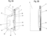
- FIGS. 3A and 3B a latch 2 or post is shown on which an assembly aid 20 is mounted.
- the mounting aid 20 is formed substantially plate-shaped and is inserted with a holding portion 21 in the groove 4 on the bolt 2 or the post 2 '.
- Bolt 12, which are already preassembled on the bolt 2 can be inserted into openings 26 on the mounting aid 20 become.
- Each opening 26 opens into a viewing window 27, which at least partially allows a view of the bolt 12, so that it can be visually checked whether a bolt 12 is mounted at this position.
- two openings 26 and viewing window 27 are provided on each assembly aid 20 so that it can also be checked via the assembly aid 20 whether the bolts 12 are arranged at a predetermined distance from each other.
- FIG. 3A is already positioned on one side a filling element 6, while on the opposite side of the bolt 2 no filling element 6 is provided. If one or more mounting aids 20 are respectively positioned on this free field on two, three or four sides, a filling element 6 can be positioned on this free field.
- Each assembly aid 20 serves to guide, wherein the mounting aid 20 has a first guide surface 22 which is provided adjacent to the holding portion 21 and extends substantially perpendicular to the plane spanned by posts 2 'and 2 bar. In the region of the outside of the filling element 6, a bend 23 or a curvature is then provided, to which a second guide surface 24 adjoins.
- This second guide surface 24 extends at an angle to the first guide surface 22, for example, the surfaces between 5 ° and 20 ° inclined to each other, so that at two parallel posts 2 'or two parallel bars 2, the mounting aids 20 are arranged spreading outward in each case can and thus form a wedge-shaped feed channel. If a filling element 6 is not supplied exactly in the space provided for this purpose, the mounting aids 20 with the guide surfaces 24 and 22 provide guidance, without any contact with the metallic bolts or an adjacent filling element 6.
- a grip portion 25 is further provided, which is formed as a recess, so that the mounting aid 20 can be easily mounted and dismounted.
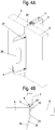
- FIGS. 4A and 4B the position is shown when the second filling element 6 is arranged in the same plane as the previously mounted filling element 6. Between the two filling elements 6, a small gap is formed, which has a width of less than 20 mm, in particular less than 25 mm or even less than 10 mm. After the positioning of the two filling elements 6, all assembly aids 20 can be pulled out of the groove 4 again, in order then to mount the respective pressure strips 8, as shown in FIG FIG. 1 is shown.
- the assembly aid 20 is shown in detail.
- the assembly aid 20 is substantially plate-shaped and comprises in the central region a kink 23 or a curvature which separates the first guide surface 22 from the second guide surface 24.
- the width of the first guide surface 22 substantially corresponds to the width of a filling element 6.
- a cross-sectional contour is selected, which can be locked or clamped to the groove 4 of a bolt 2 or post 2 'to pre-fix the mounting aid 20. It is also possible to provide on the holding portion 21 corresponding elastic elements for a clamping fixation.
- the holding portion 21 is interrupted by recesses 28, on which the bolts 21 are arranged. At the recesses 28 openings 26 are then provided for performing the threaded portions of the bolt 12.
- the bolts 12 are arranged protected by the mounting aid 20.
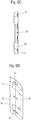
- FIGS. 6A to 6D a modified mounting aid 20 'is shown in which three openings 26 and three viewing windows 27 instead of only two openings 26 and two viewing windows 27 are provided.
- the mounting aid 20 ' is otherwise as in the embodiment of FIG. 5 formed substantially plate-shaped and comprises in the central region a kink 23 or a curvature which separates the first guide surface 22 of the second guide surface 24.
- the mounting aid 20 ' has a holding portion 21 for insertion or plugging on a groove 4 of a bolt 2 or post 2'.
- two spaced-apart mold parts 30 are made of an elastic material, in particular of an EPDM, which ensure a clamping fixation of the mounting aid 20 'on the groove 4. This prevents the assembly aid 20 'from slipping on the groove 4 after being put on.
- the number of elastic molded parts 30 can be selected depending on the length of the mounting aid 20 '.
- the holding portion 21 is provided adjacent to the mold parts 30 with recesses 28 on which the bolts 12 are arranged. The bolts 12 are arranged protected in the openings of the mounting aid 20.
- the mounting aid 20, 20 ' may be formed of a plastic or other material which has a lower hardness, in order to avoid damage to an edge region of the filling elements 6. Additionally or alternatively may be provided on the guide surfaces 22 and 24 elastic strips 29 which are glued, for example, and made of an elastic material, such as foam. As a result, when the filling element 6 strikes the mounting aid 20, it is braked elastically via the strips 29. To facilitate orientation, markings may also be provided on the assembly aid 20, 20 ', for example in order to visualize the spacing of the openings 26.
Landscapes
- Engineering & Computer Science (AREA)
- Architecture (AREA)
- Civil Engineering (AREA)
- Structural Engineering (AREA)
- Physics & Mathematics (AREA)
- Electromagnetism (AREA)
- Load-Bearing And Curtain Walls (AREA)
Applications Claiming Priority (1)
| Application Number | Priority Date | Filing Date | Title |
|---|---|---|---|
| DE102016104405.9A DE102016104405B4 (de) | 2016-03-10 | 2016-03-10 | Verfahren zur Montage einer Pfosten-Riegel-Konstruktion und Montagehilfe |
Publications (1)
| Publication Number | Publication Date |
|---|---|
| EP3216937A1 true EP3216937A1 (fr) | 2017-09-13 |
Family
ID=58054069
Family Applications (1)
| Application Number | Title | Priority Date | Filing Date |
|---|---|---|---|
| EP17156519.5A Withdrawn EP3216937A1 (fr) | 2016-03-10 | 2017-02-16 | Procédé de montage d'une construction à poteau-traverse et aide au montage |
Country Status (2)
| Country | Link |
|---|---|
| EP (1) | EP3216937A1 (fr) |
| DE (1) | DE102016104405B4 (fr) |
Cited By (2)
| Publication number | Priority date | Publication date | Assignee | Title |
|---|---|---|---|---|
| CN111021596A (zh) * | 2019-12-30 | 2020-04-17 | 广州康普顿至高建材有限公司 | 一种快速安装隔断 |
| CN115075506A (zh) * | 2022-07-21 | 2022-09-20 | 广州欧派集成家居有限公司 | 连接机构及固定装置 |
Citations (5)
| Publication number | Priority date | Publication date | Assignee | Title |
|---|---|---|---|---|
| WO2005035901A1 (fr) | 2003-09-16 | 2005-04-21 | Renovision | Cadre d'etayage pour façade |
| DE202006002614U1 (de) | 2006-02-18 | 2006-05-18 | SCHÜCO International KG | Montagehilfe und Pfosten-Riegel-Konstruktion |
| EP2246496A1 (fr) * | 2009-04-21 | 2010-11-03 | 4B Holding AG | Dispositif de fixation d'un élément d'insertion dans un élément de façade et procédé de montage d'un dispositif de fixation d'un élément d'insertion dans un élément de façade |
| US20120222386A1 (en) * | 2011-03-04 | 2012-09-06 | William Matthews | Construction panel positioning and support system and tools |
| DE102015100523A1 (de) | 2015-01-14 | 2016-07-14 | SCHÜCO International KG | Pfosten-Riegel-Konstruktion |
-
2016
- 2016-03-10 DE DE102016104405.9A patent/DE102016104405B4/de active Active
-
2017
- 2017-02-16 EP EP17156519.5A patent/EP3216937A1/fr not_active Withdrawn
Patent Citations (5)
| Publication number | Priority date | Publication date | Assignee | Title |
|---|---|---|---|---|
| WO2005035901A1 (fr) | 2003-09-16 | 2005-04-21 | Renovision | Cadre d'etayage pour façade |
| DE202006002614U1 (de) | 2006-02-18 | 2006-05-18 | SCHÜCO International KG | Montagehilfe und Pfosten-Riegel-Konstruktion |
| EP2246496A1 (fr) * | 2009-04-21 | 2010-11-03 | 4B Holding AG | Dispositif de fixation d'un élément d'insertion dans un élément de façade et procédé de montage d'un dispositif de fixation d'un élément d'insertion dans un élément de façade |
| US20120222386A1 (en) * | 2011-03-04 | 2012-09-06 | William Matthews | Construction panel positioning and support system and tools |
| DE102015100523A1 (de) | 2015-01-14 | 2016-07-14 | SCHÜCO International KG | Pfosten-Riegel-Konstruktion |
Cited By (2)
| Publication number | Priority date | Publication date | Assignee | Title |
|---|---|---|---|---|
| CN111021596A (zh) * | 2019-12-30 | 2020-04-17 | 广州康普顿至高建材有限公司 | 一种快速安装隔断 |
| CN115075506A (zh) * | 2022-07-21 | 2022-09-20 | 广州欧派集成家居有限公司 | 连接机构及固定装置 |
Also Published As
| Publication number | Publication date |
|---|---|
| DE102016104405B4 (de) | 2021-02-18 |
| DE102016104405A1 (de) | 2017-09-14 |
Similar Documents
| Publication | Publication Date | Title |
|---|---|---|
| DE102009043993B4 (de) | Hilfsvorrichtung zur Befestigung eines Distanzelementes an einem Bodenbrett | |
| EP0464367A1 (fr) | Jeu d'éléments de construction pour la réalisation d'une structure portante de plafonds | |
| EP3548412A2 (fr) | Dispositif de fixation et procédé permettant de fixer un élément de paroi dans une cabine d'ascenseur | |
| DE2610998C3 (de) | Halterung zur Befestigung von Bekleidungsplatten vor einer Bauwerkswand | |
| DE102016104405B4 (de) | Verfahren zur Montage einer Pfosten-Riegel-Konstruktion und Montagehilfe | |
| DE102019132571A1 (de) | Profilsystem zur Bildung eines Untertragrahmens für die Aufnahme von Bodenbelägen und Anschlusselement | |
| DE10013574C2 (de) | Vorrichtung und Verfahren zum lösbaren Befestigen einer Verkleidung an einer Wandung mit definierter Fuge | |
| EP2862984B1 (fr) | Structure pour le vitrage d'un bâtiment | |
| EP3988737B1 (fr) | Système de revêtement pour un mur et agencement du système de revêtement sur un mur | |
| EP2587185B1 (fr) | Moyens de connexion pouvant être connectés les uns aux autres par le profilé creux à l'aide d'au moins un écrou pour installations solaires, ainsi que système de profilé creux pour une installation solaire | |
| DE10134396C1 (de) | Bausatz zum Einsetzen eines Wandelementes in eine Wandöffnung einer doppelschaligen Ständerwand | |
| EP1647649A2 (fr) | Système de fixation de façades | |
| EP3245345B1 (fr) | Construction à montants et traverses | |
| EP2660403A1 (fr) | Support pour matière isolante | |
| DE202010008544U1 (de) | Structural-Glazing-Konstruktion | |
| DE102017102536A1 (de) | Halterung zur Befestigung einer Verkleidung an einer Gebäudewand oder -decke | |
| DE102015100525A1 (de) | Verfahren zur Montage einer Pfosten-Riegel-Konstruktion und Pfosten-Riegel-Konstruktion | |
| DE102015100523A1 (de) | Pfosten-Riegel-Konstruktion | |
| DE102012104000B4 (de) | Halter zur Fixierung eines Isolationskörpers an einer Pfosten- und Riegelanordnung und eine solche Pfosten- und Riegelanordnung | |
| DE2810981A1 (de) | Vorrichtung zur befestigung einer zarge | |
| EP1881122B1 (fr) | Rail de profilé en acier formé à froid | |
| DE102023104483A1 (de) | Trennwandinstallation und Verfahren zur Montage einer Trennwandinstallation | |
| DE102017120676A1 (de) | Deckenverkleidungssystem | |
| EP2896774A1 (fr) | Dispositif de fixation d'un corps de construction | |
| DE102016218256B4 (de) | Dachfenster |
Legal Events
| Date | Code | Title | Description |
|---|---|---|---|
| PUAI | Public reference made under article 153(3) epc to a published international application that has entered the european phase |
Free format text: ORIGINAL CODE: 0009012 |
|
| STAA | Information on the status of an ep patent application or granted ep patent |
Free format text: STATUS: THE APPLICATION HAS BEEN PUBLISHED |
|
| AK | Designated contracting states |
Kind code of ref document: A1 Designated state(s): AL AT BE BG CH CY CZ DE DK EE ES FI FR GB GR HR HU IE IS IT LI LT LU LV MC MK MT NL NO PL PT RO RS SE SI SK SM TR |
|
| AX | Request for extension of the european patent |
Extension state: BA ME |
|
| STAA | Information on the status of an ep patent application or granted ep patent |
Free format text: STATUS: REQUEST FOR EXAMINATION WAS MADE |
|
| 17P | Request for examination filed |
Effective date: 20180212 |
|
| RBV | Designated contracting states (corrected) |
Designated state(s): AL AT BE BG CH CY CZ DE DK EE ES FI FR GB GR HR HU IE IS IT LI LT LU LV MC MK MT NL NO PL PT RO RS SE SI SK SM TR |
|
| STAA | Information on the status of an ep patent application or granted ep patent |
Free format text: STATUS: EXAMINATION IS IN PROGRESS |
|
| 17Q | First examination report despatched |
Effective date: 20210525 |
|
| GRAP | Despatch of communication of intention to grant a patent |
Free format text: ORIGINAL CODE: EPIDOSNIGR1 |
|
| STAA | Information on the status of an ep patent application or granted ep patent |
Free format text: STATUS: GRANT OF PATENT IS INTENDED |
|
| INTG | Intention to grant announced |
Effective date: 20230614 |
|
| STAA | Information on the status of an ep patent application or granted ep patent |
Free format text: STATUS: THE APPLICATION IS DEEMED TO BE WITHDRAWN |
|
| 18D | Application deemed to be withdrawn |
Effective date: 20231025 |