EP3217057B1 - Dispositif et procédé de fixation destiné à rendre étanche un passage de conduite dans une cloison d'un bâtiment - Google Patents
Dispositif et procédé de fixation destiné à rendre étanche un passage de conduite dans une cloison d'un bâtiment Download PDFInfo
- Publication number
- EP3217057B1 EP3217057B1 EP17156192.1A EP17156192A EP3217057B1 EP 3217057 B1 EP3217057 B1 EP 3217057B1 EP 17156192 A EP17156192 A EP 17156192A EP 3217057 B1 EP3217057 B1 EP 3217057B1
- Authority
- EP
- European Patent Office
- Prior art keywords
- distribution
- sleeve
- channel
- wall
- passage
- Prior art date
- Legal status (The legal status is an assumption and is not a legal conclusion. Google has not performed a legal analysis and makes no representation as to the accuracy of the status listed.)
- Active
Links
Images


Classifications
-
- F—MECHANICAL ENGINEERING; LIGHTING; HEATING; WEAPONS; BLASTING
- F16—ENGINEERING ELEMENTS AND UNITS; GENERAL MEASURES FOR PRODUCING AND MAINTAINING EFFECTIVE FUNCTIONING OF MACHINES OR INSTALLATIONS; THERMAL INSULATION IN GENERAL
- F16L—PIPES; JOINTS OR FITTINGS FOR PIPES; SUPPORTS FOR PIPES, CABLES OR PROTECTIVE TUBING; MEANS FOR THERMAL INSULATION IN GENERAL
- F16L5/00—Devices for use where pipes, cables or protective tubing pass through walls or partitions
- F16L5/02—Sealing
-
- G—PHYSICS
- G02—OPTICS
- G02B—OPTICAL ELEMENTS, SYSTEMS OR APPARATUS
- G02B6/00—Light guides; Structural details of arrangements comprising light guides and other optical elements, e.g. couplings
- G02B6/44—Mechanical structures for providing tensile strength and external protection for fibres, e.g. optical transmission cables
- G02B6/4439—Auxiliary devices
- G02B6/4459—Ducts; Conduits; Hollow tubes for air blown fibres
-
- G—PHYSICS
- G02—OPTICS
- G02B—OPTICAL ELEMENTS, SYSTEMS OR APPARATUS
- G02B6/00—Light guides; Structural details of arrangements comprising light guides and other optical elements, e.g. couplings
- G02B6/46—Processes or apparatus adapted for installing or repairing optical fibres or optical cables
- G02B6/47—Installation in buildings
- G02B6/475—Mechanical aspects of installing cables in ducts or the like for buildings
-
- H—ELECTRICITY
- H02—GENERATION; CONVERSION OR DISTRIBUTION OF ELECTRIC POWER
- H02G—INSTALLATION OF ELECTRIC CABLES OR LINES, OR OF COMBINED OPTICAL AND ELECTRIC CABLES OR LINES
- H02G3/00—Installations of electric cables or lines or protective tubing therefor in or on buildings, equivalent structures or vehicles
- H02G3/22—Installations of cables or lines through walls, floors or ceilings, e.g. into buildings
Definitions
- the invention relates to a device and a method for fastening and sealing a cable bushing in a wall passage of a building wall. Furthermore, the invention relates to a distributor sleeve, such as a passage sleeve, injection sleeve or sieve sleeve, for such a device.
- a device for fastening and sealing the line leadthrough through a wall opening of the building wall, such as an empty pipe, is out EP 2 410 222 B1 known.
- a distributor sleeve as a rigid passage pipe is arranged concentrically between the passage wall and the empty pipe to be fastened, a sealing bead being provided on the outside of the building wall, which can be clamped against the outside of the building wall via a tensioning device to be operated on the inside of the building wall.
- a filling hose is inserted deeply, through which a viscous, flowing hardening substance can be introduced into the center of a hollow block of the building wall.
- the hardening substance reaches the outside of the rigid distributor sleeve in order to be able to exit further into the hollow block at the wall passage and after hardening to create a fluid-tight seal for fastening the distributor sleeve and the empty pipe located therein to the wall passage.
- EP 2 071 688 B1 discloses a method for fastening a cable bushing in the wall passage of the building wall and a distributor sleeve as a flexible hose.
- the special feature of the distributor sleeve is that it consists of a flexible jacket into which perforations are made, which only allows the hardening substance to escape when a pressure threshold value is exceeded.
- EP 2 645 507 A1 shows a cable duct for fastening in a building wall.
- a device for fastening and sealing a line leadthrough, such as an empty pipe, leading through a wall passage of a building wall on and opposite the building wall, in particular in the area of the wall passage.
- the sealing and fastening device comprises a distributor sleeve which surrounds the line bushing and which can either be rigid as a sleeve or flexible as a hose, in particular with a wall thickness of less than 1 mm.
- the outside of the line bushing (the empty pipe) and the inside of the distributor sleeve form in particular in the case of an essentially precise concentric arrangement of the distributor sleeve around the line leadthrough an annular, in particular circular, circumferential annular space gap, the radial width of which is in particular continuously greater than 0.5 mm and less than 5 mm or 3 mm.
- the annular gap is preferably between 1.5 mm and 2.5 mm, especially at about 1.5 mm.
- the annular space gap can extend with a constant radial distance between the distributor sleeve and the line bushing in the circumferential direction and in the axial direction. Surprisingly, it was found that this narrow annular space gap is sufficient to provide a good distribution of the hardening substance. In this way, the volume of the empty tube can be maximized, the tightness of the attachment of the empty tube to the wall passage being optimized.
- the outside diameter of the distributor sleeve can be defined to be greater than 10 mm and / or less than 100 mm, preferably greater than 30 mm and less than 70 mm.
- the annular gap space in particular with a precise concentric arrangement of the distributor sleeve around the line bushing, has a constant radial width along the extension of the line bushing, in particular when a rigid distributor sleeve is used or with a uniform internal pressure of the distributor sleeve.
- the distributor sleeve comprises a sleeve-shaped sealing end or sealing sleeve, which in particular faces the inside of the building.
- the end of the seal preferably forms a cylindrical inner sealing surface which has an inner diameter which is adapted to a particularly constant outer diameter of the line bushing, such as the empty pipe, in such a way that a play-free fit, in particular a transition fit or press fit, is formed between the line bushing and the distributor sleeve, in particular to implement a seal against an axial exit of the hardening substance from the annular gap.
- the invention relates to the distributor sleeve itself, which can be used in particular with the fastening and sealing device mentioned above.
- the distributor sleeve serves to enclose the line leadthrough, such as the empty pipe, in particular concentrically and thereby to form the annular, in particular circular, gap space.
- the flowable hardening substance should be introduced into the gap.
- the distributor sleeve has a rigid or flexible envelope body with a plurality of through holes for radially passing the curing substance from the inside of the distributor sleeve to the outside thereof in order to come into contact with the inside of the building wall passage.
- the distributor collar has, in particular on an axial end section, a contact flange, in particular for contacting a building side, preferably an outer wall of the building in order to give the envelope body a clear axial and possibly also a radial position for the assembly of the distributor sleeve, in particular the sealing and fastening device.
- the contact flange has a connection via which the hardening substance can be introduced into the gap.
- the connection can be used to connect an external curing substance source.
- the connection is followed by an inlet channel for guiding the particularly pasty curing substance into the gap.
- At least the enveloping body and the connection with the channel wall limitation of the inlet channel and optionally the contact flange are made from a piece of material, in particular injection molded from a plastic piece. It was shown that an extremely compact distributor sleeve and a compact sealing and fastening device can be achieved with this technical measure and that the gap space can be designed with a significantly smaller volume. In this way, the volume of the empty pipe can be significantly increased. It was also shown that the operability of the sealing and fastening device during assembly and when injecting the hardening substance is significantly simplified, because according to the invention a violation of the separate line structures is largely ruled out.
- the inlet channel has a connection-side channel end section which extends axially from a free connection end, in particular essentially up to the axial height of a contact surface of the contact flange or of the building contact surface, and / or essentially has a cylindrical passage cross section.
- the inlet duct has a transition duct section which adjoins the duct end section in steps in the axial direction. The radial outer boundary walls of the transition duct section spring back radially inwards compared to the outer boundary walls of the duct end section, as a result of which a radial height of the duct cross section is reduced.
- the wall section of the channel delimiting in the circumferential wall direction is widened in order to compensate for a reduction in cross-section or at least to keep it small or to compensate completely.
- the transition duct section has a radially inner passage opening, via which a fluid connection between the inlet duct and the gap space is achieved.
- the contact flange has an inlet channel, which in particular comprises a cylindrical channel cross section on the connection side.
- the inlet duct opens into the rotationally asymmetrical transition duct section, the radial, outer or inner boundary wall of which, in comparison with the cylindrical cross section, springs back radially inwards or outwards, in particular by a preferably equal radial offset of at least 1 mm, as a result of which the radial cross-sectional height of the transition duct section is reduced compared to the inlet duct.
- the outer wall of the channel transition section is widened radially outward, preferably by less than 3 mm, with respect to the outer wall of the longitudinally extending distribution channel, which is formed on the inside of the enveloping body by the in particular cylindrical enveloping body, the offset outer wall extending by more than 10 mm extends in the axial longitudinal direction from the contact surface into the interior of the wall passage and then opens vanishingly into the cylindrical enveloping body by means of a step.
- the wall thickness along the entire inlet channel from the connection to the gap space is preferably essentially constant.
- a channel inner wall of the channel transition section can be provided, in particular in the area of the axial height of the contact surface, with a passage opening for fluidly connecting the inlet channel to the distribution channel adjoining the transition channel.
- the passage opening can extend axially in the longitudinal direction by at least 5 mm, wherein it has a smaller circumferential width than the axial length.
- an upper (radially outer) channel boundary wall section of the enveloping body is free of any through holes and / or slots.
- the channel boundary wall section without through holes can have a minimum circumferential width of at least 5 mm, in particular the through-hole-free envelope body section extending in the longitudinal direction by at least half the longitudinal extent of the envelope body.
- at least a number of in particular identical through holes and / or slots adjoins.
- the invention relates to a hose-like, in particular membrane-like, in particular manually deformable, flexible distributor sleeve for the device for fastening and sealing the line bushing leading through a wall passage through the building wall, as is also defined above, for example.
- the line bushing can be an empty pipe in which the electrical conductors or optical fibers are to be arranged.
- the flexible distributor sleeve is to be attached to and opposite the building wall, the flexible distributor sleeve forming a circumferential, in particular circular, gap space with the line bushing with which it can be arranged concentrically.
- the distributor sleeve has a plurality of through elongated holes which are formed by slots with a minimum slot width of at least 0.3 mm, 0.4 mm or 0.5 mm.
- the slot length and the slot width are dimensioned such that in the assembled state, in particular when a hardening substance pressure is applied to the distributor sleeve, the opposite slot edges do not come into contact but the slot remains open to ensure that the hardening substance can pass through.
- the injection pressure of the hardening substance into the gap does not have to be applied to provide a passage cross section in the slot.
- the flexible distributor sleeve is preferably made of one piece of elastomer material, in particular injection molded. Additionally and / or alternatively, at least one row of slots extending in the axial longitudinal direction of the distributor sleeve is provided with slots arranged in the same slot orientation, preferably the same slot length and width. In particular, two rows of slots which are adjacent to one another can each have a slot length which is different from one another, there being in particular a length difference of at least 5 mm, 1 cm or 2 cm, in particular the slot width of the slots of both rows of slots, in particular all rows of slots, being essentially the same size.
- the slots are already realized in the course of the production of the flexible distributor sleeve, for example by means of a corresponding injection molding process.
- the slots in particular of constant slot width, preferably extend in the same axial position exclusively in the circumferential direction of the distributor sleeve.
- the slots made in the enveloping body can have an elongated hole shape, in particular with parallel elongated hole edges and / or rounded hole ends.
- the invention relates to a rigid distributor sleeve, in particular made of a rigid material, such as metal or plastic, for a device, in particular as described above, for fastening and sealing a line leadthrough through the wall passage of the building wall, such as an empty pipe, to and against the building wall and for enclosing it the cable bushing with the formation of an annular, in particular annular, surrounding gap space.
- a flowable hardening substance can be introduced into the gap, which realizes the final sealing function and fastening function.
- the rigid distributor sleeve comprises an enveloping body with a plurality of passage openings through which the hardening substance can emerge from the gap space to the wall passage.
- the passage openings each have an elongated hole shape, the passage width of which, in particular in the longitudinal direction of the elongated hole, is less than 1 mm and greater than 3 mm, preferably between 0.4 mm and 0.8 mm.
- this elongated hole size proved to be advantageous in that a sufficient passage quantity can be achieved through the passages without impairing the stability of the enveloping body too much.
- a uniform distribution of the elongated holes dimensioned above ensures a large-volume distribution of the hardening substance, whereby on the one hand an improved sealing effect and a stronger fastening resistance can be generated.
- an area ratio between a total passage cross section of the passage openings, which results from the sum of all passage cross sections of the passage opening in the enveloping body, and the overall outer circumference of the in particular cylindrical enveloping body is greater than 0.5 and less than 0.7, preferably between 0 , 52 and 0.6, in particular between 0.55 and 0.65.
- the distributor sleeve has at least four, five or six rows of identical through elongated holes, the rows being arranged distributed evenly around the circumference. It should be clear that in the region of the portion of the enveloping body that delimits the distribution channel radially on the outside, there are preferably no elongated holes in some cases.
- a first row of pass-through holes has a short hole length of less than 4 mm and another one with a large slot length of more than 4 mm or 5 mm.
- the enveloping body has a passage area that is free of elongated holes and has a width of at least 4 mm, 5 mm or 6 mm. The area without a slot extends through at least half the total length of the enveloping body, in particular has the same length as the distribution channel on the inside.
- the sealing and fastening device is designed with an above-mentioned sleeve, depending on the embodiment.
- the invention relates to a method for fastening and sealing a line lead-through, such as an empty pipe, leading through a wall passage of a building wall to and opposite the building wall, in particular the above-mentioned device and / or the above-mentioned distributor sleeves being used.
- a line lead-through such as an empty pipe
- the invention relates to a line bushing, such as an empty pipe, leading through a wall passage of a building wall on and opposite the building wall.
- a distributor sleeve is dimensioned such that, in particular when the distributor sleeve is arranged concentrically around the line bushing, an annular gap is formed, the radial width of which is in particular greater than 0.5 mm and in particular less than 5 mm.
- the invention preferably relates to a method in which a contact flange, which is in particular made in one piece with the distributor sleeve, is attached, in particular braced, to a building wall side, in particular to a building outer wall side.
- a hardening substance such as Tangit, is injected, in particular, onto the contact flange in order to fasten the line bushing to the wall passage.
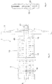
- the sealing and fastening device 1 essentially comprises as main components: a distributor sleeve 3, which can be designed, for example, as a rigid passage sleeve with radial passage holes or as a passage hose with radial passage holes that can be flexibly deformed and adapted to the rigid tubular passage sleeve (the distributor sleeve 3 can also be in the form of an injection sleeve) or sieve sleeve); and an empty pipe 5, which for example has a standard diameter of 32 cm ( Fig.
- the distributor sleeve 3 defines an enveloping body 13 which completely surrounds the outside of the empty tube 5, in particular adjacent to the outside of the building A, in the circumferential direction. Through openings in the enveloping body 13 provide a direct radial connection from the outside of the empty tube 5 to the outside of the enveloping body 13.
- the envelope body 13 has a certain longitudinal extent (along the longitudinal axis L) and should have at least a quarter of the total extent of the wall passage, but at most half or two thirds of the total axial length of the wall passage. Only a portion 9 of the empty tube 5 near the end is completely enclosed by the distributor sleeve 3, forming an encircling annular gap 31.
- the sealing and fastening device 1 comprises a sealing and tensioning device 7, which can be used on an end of the empty tube 5 facing the building inner wall I, so that the tensioning device 7, in cooperation with a contact flange 11 arranged at the opposite end, the empty tube 5 in Assembled state, especially under tension.
- the sealing and tensioning device 7 is closer in the already published patent application DE 10 2010 026 082 A1 explained, the content of which is to be considered as a further disclosure, in particular with regard to the functioning and arrangement of the sealing and tensioning device 7.
- FIG. 2 The device 1 according to the invention for fastening and sealing the empty tube 5 is shown in cross section, the tensioning and sealing device 7 being mounted in the empty tube 5.
- a driver By turning a grip element 27 of the tensioning seal 7, a driver is pushed in the axial direction, as a result of which two sealing beads 29 are pressed together axially and expand radially in order to form a sealing contact with the inside of the empty tube 5.
- the enveloping body 13 comprises a multiplicity of substantially uniformly distributed passage elongated holes 15, which are arranged in several axial rows one behind the other at essentially the same axial distance.
- the arrangement of the through elongated holes 15 will be referred to later, in particular with reference to FIG 10 and 11 received.
- a sealing sleeve 17 is connected in one piece to the envelope body 13, which has a precisely fitting inner circumference with respect to the outer dimension of the empty tube 5 or a slightly smaller inner circumference in order to provide a seal in the axial direction between the envelope body 13 and to provide the empty tube 5.
- the coaxial, essentially annular, in particular circular, circumferential gap space 31 is formed, which ends at the sealing sleeve 17.
- the shape of the gap 31 also depends on the rigidity of the distributor sleeve 3 and the injection pressure with which a pasty fastening compound is to be introduced into the gap 31.
- a gap 31 that does not run continuously is to be assumed, while the gap 31 extends continuously in the circumferential and axial direction L with a passage sleeve made of rigid material with a constant radial width or with a uniform gap pressure 31.
- radially inwardly projecting spacing ribs can be provided from the enveloping body 13, which extend in the axial longitudinal direction L and rest on the empty tube by a spacing and coaxial centering of the inside of the enveloping body on the Ensure that the outside of the empty pipe 5 fits tightly and thus form the gap as evenly as possible.
- the contact flange 11 connects in one piece, which is disc-shaped and has a flat contact surface 10 facing the building outer wall A, which is provided with a sealing tape 12, such as a Butyl tape is provided to form a fluid-tight seal when it is applied to the outer wall A of the building.
- a sealing tape 12 such as a Butyl tape
- a connection piece or injection nozzle 21 is formed in one piece with the contact flange 11, which forms a channel end section 22 or inlet channel, in particular a circular cylindrical cross section, which for forwarding with the distribution channel 19 formed on the inside of the envelope body the curing substance is connected beyond the center of the enveloping body 13.
- the injection nozzle 21 forms the circular cylindrical connection for easy connection of an injection hose or other filling aid (not shown), and has an inner diameter of 5 mm to 20 mm, in particular approximately 10 mm.
- a pasty, flowable hardening substance such as Tangit
- the connecting piece 21 is arranged eccentrically to the longitudinal axis L of the distributor sleeve 3 essentially at a radial height r of the cylindrical envelope body 13, which essentially corresponds to the maximum radial distance of the distributor sleeve 3, in particular slightly larger than the maximum radial distance of the outer circumference of the empty tube 5 from the longitudinal axis L. and is approximately slightly smaller than the radial distance between the inside of the wall passage 18 and the longitudinal axis L.
- the connecting piece 21 forms the outside inlet channel for the distribution channel 19 adjoining it via a transition channel section and extending parallel to the longitudinal axis L, which is located in the interior of the enveloping body 13 and extends along half of the axial length of the distribution sleeve 3 on the inside thereof.
- the distribution channel 19 is a channel structure partially delimited by the enveloping body 13, which is open towards the empty tube 5 and is also radially delimited by the latter.
- the distribution channel 19 is delimited in the circumferential direction by two longitudinal ribs 32 extending in the longitudinal direction L, which are formed in one piece with the enveloping body 13 and lie essentially sealingly against the empty tube 5 and thus prevent lateral circumferential outflow from the distribution channel 19, so that the pasty curing substance is due to of the injection pressure should flow exclusively along the distribution channel 19.
- the long ribs 32 are offset from one another in the circumferential direction by approximately 3 ° to 50 ° and run parallel to one another.
- the long ribs 32 end after about half the total axial extension of the distributor sleeve 3, where the distribution channel 19 also ends, so that the hardening substance emerging there can freely spread in the circumferential, radial and axial directions.
- the distribution channel 19 does not extend axially over the entire longitudinal extent of the enveloping body 13, but over at least half but less than three-quarters of the total longitudinal extent of the enveloping body 13.
- the distribution channel 19 ends when the long ribs 32 spring back towards the inside of the cylindrical enveloping body 13. This exit point is provided with the reference symbol u.
- the distribution channel 19 is in the shape of a partial ring section and changes its cross section in the region of the dome-shaped widening 16, which is formed in the axial connection to the contact flange 11.
- the distribution channel 19 is delimited radially on the outside by the correspondingly assigned cylindrical section of the enveloping body 13.
- An additional stabilizing rib 33 which is provided for stabilizing / centering the enveloping body 13 on the empty tube 5, is assigned to the pair of long ribs 32, essentially diametrically opposite the longitudinal axis L.
- the long ribs 32 and the stabilizing rib 33 are made in one piece with the enveloping body 13, in particular from plastic.
- the stabilizing rib 33 extends in the axial direction as far as the long ribs 32 in order to achieve an unimpeded distribution of the hardening substance in the rib-free end region of the distributor sleeve 3.
- the radial widening 16 of the enveloping body 13 Adjacent to the building exterior wall side A, projecting a few millimeters into the wall passage, the radial widening 16 of the enveloping body 13 is formed on the outer region of a transition duct section connecting the distribution duct 19 to the inlet duct.
- the widening 16 and the radial outer boundary area of the distribution channel 19 in the axial connection to the widening 16 should, according to a preferred embodiment of the invention, be formed free of any passage opening, so that it is ensured that the amount of the hardening substance injected reaches the outlet area u of the distribution channel 19 without loss .
- a transition channel section 20 forms a radial recess despite the widening 16.
- the widening 16 serves to extend from the cylindrical inlet cross section of the injection nozzle 21 to the distribution channel 19 ( Fig. 8 ) to create a gradual cross-sectional change towards the distribution channel 19.
- the passage cross section of the distribution channel 19 is through the circumferential side Long ribs 32 and changed in an oval cross-section with respect to the cylindrical injection nozzle 21.
- the oval cross section in the channel transition 20 is radially compressed with respect to the channel end section 22 of the injection nozzle 21 and widened in the circumferential direction.
- a radially inner, axial nozzle extension 25 of the injection nozzle 21 is provided, which radially projects radially on the inside compared to the inner channel end section of the injection nozzle 21 and extends axially inward beyond the contact surface 10 into the wall passage 18.
- the internal passage opening 26 is formed in order to open the channel on the inside towards the empty pipe 5 and to connect the channel structure to the distribution channel 19.
- the passage cross section of the injection nozzle is essentially circular up to the contact surface 10, a sudden cross section reduction being provided in the region of the transition channel section 20, which comprises the widening 16.
- the transition channel section 20 extends axially into the wall passage 18 over the position of the contact surface 10, the transition channel section 20 being initially delimited axially on the inside by the nozzle extension 25.
- the nozzle extension 25 ends several millimeters, in particular 5 mm to 15 mm, from the reduction in the passage cross section and opens into the inside passage opening 26.
- the transition duct section 20 is delimited on the outside and in the circumferential direction by the widening 16 and by the long ribs 32.
- the distribution channel 19 only allows an exit in the circumferential direction from the point u, so that a pasty curing material which can be introduced via the injection nozzle 21 enters the entire gap 31 from the external point u. From the point u, the hardening substance is distributed evenly in the circumferential direction, radial direction and axial direction both in the gap space 31 and in the direction of the building outer wall side A.
- the injection nozzle 21, the contact flange 11 and the enveloping body 13 and the long ribs 32 delimiting the distribution channels 19 are made of one Injection molded plastic.
- a centering ring 28 is slipped on, which is intended to center the empty tube 5 in the wall passage adjacent to the inside of the wall.
- a plurality of rows of elongated holes 15 are made in the enveloping body 13 in order to provide a radial exit of the flowable hardening substance (not shown in more detail) from the gap space 31 filled via the injection nozzle 21 in the radial direction towards the outside of the enveloping body 13 and towards the inside of the wall passage 18.
- the elongated hole extension of the through holes 15 is aligned in the circumferential direction, that is to say perpendicular to the longitudinal axis L, the circumferential length of the through elongated holes 15 being able to be different for each row.
- the circumferential length of the through slots 15 may be constant.
- the passage elongated holes 15 are arranged at the same axial distance from one another in all rows.
- the axial rows of the through elongated holes 15 are separated by a continuous bridge section 45 of the enveloping body (13) from 1 mm to 5 mm, each bridge section 15 separating two circumferentially adjacent through elongated holes 15 from one another.
- the distributor sleeve 3 is provided on the entire circumference with the through elongated holes, which are dimensioned in such a way that a sufficient occurrence of the hardening substance from the gap space 31 to the inside of the wall passage 18 is ensured. Only in the circumferential and longitudinal extension of the distribution channel 19 are no passages formed in the enveloping body 13.
- the through slots 15 are each arranged in a row, the through slots 15 of each row having the same length or circumferential extent. Adjacent to the distribution channel 19 are a series of elongated rows of holes with a first length, in particular 6 mm, the adjacent row of elongated holes may have a second length, in particular 3.5 mm.
- the through elongated holes 15 are either made in a flexibly deformable envelope body 13 or in a rigid sleeve body 13.
- the elongated holes have a width of greater than 0.3 mm and less than 1 mm, preferably between 0.4 mm and 0, 8 mm, trained.
- the through elongated holes 15 arise in the course of the manufacturing process, in particular the injection molding process of the enveloping body 13 and can be worked out in such a dimensionally precise manner that a reworking of the through elongated holes 15 is not necessary. It is clear that a material removal process, such as stamping or sawing, can be used in particular for a rigid material for the enveloping body 13.
- the through elongated holes 15 are in particular of such a width that the opposite elongated hole sides do not touch in the assembled state, but the through elongated hole opening always remains open, even if no hardening substance has been introduced.
- the flexible, tubular casing body 13 can be formed from a rubber-elastic material and have a wall thickness of less than 1 mm.
- the casing body 13 can also be formed by a rigid material, in particular a plastic material, preferably a thermoset material or a thermoplastic material, and have a wall thickness of more than 2 mm.
- the passage-free area fraction is preferably between 50% and 70%, in particular 50% to 60% for an injection sleeve of 32 cm and between 60% and 70% for an injection sleeve of 50 cm.
Landscapes
- Engineering & Computer Science (AREA)
- Physics & Mathematics (AREA)
- Civil Engineering (AREA)
- Structural Engineering (AREA)
- General Physics & Mathematics (AREA)
- Optics & Photonics (AREA)
- General Engineering & Computer Science (AREA)
- Mechanical Engineering (AREA)
- Installation Of Indoor Wiring (AREA)
- Laying Of Electric Cables Or Lines Outside (AREA)
Claims (15)
- Dispositif (1) pour fixer et étanchéifier un passage de conduit passant à travers un passage mural (18) d'une paroi de bâtiment, comme un fourreau (5), sur et en face de la paroi de bâtiment, comprenant le passage de conduit, un manchon de distribution (3) entourant le passage de conduit, qui comporte un corps d'enveloppe (13) avec plusieurs fentes de passage ou trous de passage (15) pour un passage radial d'une substance durcissante d'un côté intérieur du manchon de distribution (3) vers le côté extérieur de celui-ci et un espace de séparation annulaire (31) périphérique de forme annulaire se formant entre un côté extérieur du passage de conduit et un côté intérieur du manchon de distribution (3) dont la largeur radiale est formée supérieure à 0,5 mm et inférieure à 5 mm, sachant qu'un conduit de distribution (19) s'étendant en direction longitudinale axiale du manchon de distribution (3) sur un côté intérieur du corps d'enveloppe (13) est formé pour transférer la substance durcissante.
- Dispositif (1) selon la revendication 1, caractérisé en ce que le conduit de distribution (19) s'étend d'un conduit d'entrée (22) sur une section de conduit de transfert (20) s'y raccordant, longitudinalement sur la moitié de la longueur axiale du manchon de distribution (3) sur le côté intérieur de celui-ci.
- Dispositif (1) selon la revendication 1 ou 2, caractérisé en ce que le conduit de distribution (19) est formé sous la forme d'une structure de conduit en partie limitée par le corps d'enveloppe (13), laquelle est ouverte vers le fourreau (5) et est également limitée radialement par celui-ci.
- Dispositif (1) selon l'une quelconque des revendications 1 à 3, caractérisé en ce que le conduit de distribution (19) est limité dans la direction périphérique par deux nervures longitudinales (32) s'étendant en L dans la direction longitudinale, qui sont constituées en une seule pièce avec le corps d'enveloppe (13) et reposent pour l'essentiel de façon hermétique sur le fourreau (5) et évitent de ce fait un écoulement périphérique latéral du conduit de distribution (19) de telle manière en particulier que la substance durcissante pâteuse s'écoule exclusivement le long du conduit de distribution (19) qu' en raison de la pression d'injection.
- Dispositif (1) selon la revendication 4, caractérisé en ce que les nervures longitudinales (32) se terminent après à peu près la moitié de l'extension totale axiale du manchon de distribution (3), où se termine également le conduit de distribution (19) de telle manière que la substance durcissante sortant à cet endroit peut librement se propager en direction périphérique, radiale et axiale.
- Dispositif (1) selon l'une quelconque des revendications précédentes, caractérisé en ce que le conduit de distribution (19) ne s'étend pas axialement sur toute l'extension longitudinale du corps d'enveloppe (13), mais sur au moins la moitié mais moins des trois quarts de l'extension totale longitudinale du corps d'enveloppe (13).
- Dispositif (1) selon l'une quelconque des revendications 4 ou 5, caractérisé en ce que le conduit de distribution (19) se termine à un emplacement de sortie u avec le retrait des nervures longitudinales (32) vers le côté intérieur du corps d'enveloppe cylindrique (13).
- Dispositif (1) selon la revendication 7, caractérisé en ce que le conduit de distribution (19) ne permet une sortie dans la direction périphérique qu'à partir de l'emplacement de sortie u de telle manière qu'une substance durcissante pâteuse, qui peut être introduite par une tubulure d'injection (21), parvient dans tout l'espace de séparation (31) à partir de l'emplacement de sortie u.
- Dispositif (1) selon l'une quelconque des revendications 7 ou 8, caractérisé en ce que la substance durcissante se propage de l'emplacement de sortie u de façon uniforme en direction périphérique, en direction radiale et en direction axiale tant dans l'espace de séparation (31) qu'en direction de la paroi de bâtiment.
- Dispositif (1) selon l'une quelconque des revendications précédentes, caractérisé en ce que le conduit de distribution (19) s'étend d'un conduit d'entrée (22) sur une section de conduit de transfert (20) s'y raccordant le longitudinalement sur la moitié de la longueur axiale du manchon de distribution (3) sur le côté intérieur de celui-ci, sachant qu'un élargissement (16) est formé dans la zone de la section de conduit de transfert (20), qui forme une modification de section progressive du conduit d'entrée (22) au conduit de distribution (19).
- Dispositif (1) selon l'une quelconque des revendications précédentes, caractérisé en ce que le l'espace de séparation annulaire (31) se situe entre 1,5 mm et 2,5 mm et/ou le diamètre extérieur du manchon de distribution (3) est dimensionné supérieur à 10 mm et inférieur à 100 mm.
- Dispositif (1) selon l'une quelconque des revendications précédentes, caractérisé en ce que l'espace de séparation annulaire (31) comporte une largeur radiale constante le long de l'extension du passage de conduit.
- Dispositif (1) selon l'une quelconque des revendications précédentes, caractérisé en ce que le manchon de distribution (3) comporte une extrémité étanche en forme de manchon tournée vers le côté intérieur du bâtiment (I), laquelle forme une surface étanche intérieure cylindrique, laquelle comporte un diamètre intérieur qui est adapté à un diamètre extérieur constant du passage de conduit de telle manière qu'un ajustage sans jeu est formé entre le passage de conduit et le manchon de distribution (3) pour réaliser une étanchéification vis-à-vis d'une sortie axiale de la substance durcissante de l'espace de séparation annulaire (31).
- Procédé pour fixer et étanchéifier un passage de conduit passant à travers un passage mural (8) d'une paroi de bâtiment, comme un fourreau (5), sur et en face de la paroi de bâtiment, pour lequel un manchon de distribution est dimensionné de telle manière qu'avec une disposition concentrique du manchon de distribution autour du passage de conduit, un espace de séparation (31) en forme d'anneau circulaire est formé, dont la largeur radiale est formée supérieure à 0,5 mm et inférieure à 5 mm et pour lequel une substance durcissante est dirigée par le biais d'un conduit de distribution (19) formé sur un côté intérieur du manchon de distribution (3), s'étendant en direction longitudinale axiale du manchon de distribution (3) et passe par plusieurs fentes de passage ou trous de passage (15) du manchon de distribution (3) radialement du côté intérieur du manchon de distribution (3) au côté extérieur de celui-ci.
- Procédé selon la revendication 14 pour lequel une bride d'appui (11) fabriquée en une pièce avec le manchon de distribution est placée sur un côté de la paroi de bâtiment, sachant qu'une substance durcissante est injectée sur la bride d'appui pour fixer le passage de conduit sur le passage mural.
Applications Claiming Priority (1)
| Application Number | Priority Date | Filing Date | Title |
|---|---|---|---|
| DE102016104129.7A DE102016104129B4 (de) | 2016-03-07 | 2016-03-07 | Vorrichtung, Verteilermanschette und Verfahren zum Befestigen und Abdichten einer Leitungsdurchführung in einem Wanddurchgang einer Gebäudewand |
Publications (3)
| Publication Number | Publication Date |
|---|---|
| EP3217057A2 EP3217057A2 (fr) | 2017-09-13 |
| EP3217057A3 EP3217057A3 (fr) | 2017-10-25 |
| EP3217057B1 true EP3217057B1 (fr) | 2020-07-22 |
Family
ID=58098448
Family Applications (1)
| Application Number | Title | Priority Date | Filing Date |
|---|---|---|---|
| EP17156192.1A Active EP3217057B1 (fr) | 2016-03-07 | 2017-02-15 | Dispositif et procédé de fixation destiné à rendre étanche un passage de conduite dans une cloison d'un bâtiment |
Country Status (6)
| Country | Link |
|---|---|
| EP (1) | EP3217057B1 (fr) |
| DE (1) | DE102016104129B4 (fr) |
| DK (1) | DK3217057T3 (fr) |
| ES (1) | ES2828301T3 (fr) |
| HU (1) | HUE052458T2 (fr) |
| PT (1) | PT3217057T (fr) |
Families Citing this family (4)
| Publication number | Priority date | Publication date | Assignee | Title |
|---|---|---|---|---|
| DE102018007251B4 (de) * | 2018-09-14 | 2026-02-12 | Langmatz Gmbh | Vorrichtung zum Durchführen einer Speedpipe durch eine Wandbohrung |
| DE102019108986A1 (de) * | 2019-04-05 | 2020-10-08 | Langmatz Gmbh | Vorrichtung zum Durchführen wenigstens einer Leitung durch eine Wandbohrung |
| DE102019133788B4 (de) * | 2019-12-10 | 2021-06-17 | Langmatz Gmbh | Vorrichtung zum Durchführen wenigstens eines Glasfaser-Kabels durch eine Wandbohrung |
| CN110985763B (zh) * | 2019-12-13 | 2024-04-16 | 北京建工集团山西建设有限公司 | 穿越混凝土基础底板地源热泵管的防水结构及其施做方法 |
Citations (3)
| Publication number | Priority date | Publication date | Assignee | Title |
|---|---|---|---|---|
| US2897533A (en) * | 1956-02-16 | 1959-08-04 | Gen Motors Corp | Grommets, bushings and the like |
| US20090315275A1 (en) * | 2005-07-13 | 2009-12-24 | Johannes Alfred Beele | System for Sealing a Space Between an Inner Wall of a Tubular Opening and At Least One Tube or Duct At Least Partly Received In the Opening |
| US20130313787A1 (en) * | 2011-03-14 | 2013-11-28 | Sumitomo Wiring Systems, Ltd. | Seal structure for grommet |
Family Cites Families (6)
| Publication number | Priority date | Publication date | Assignee | Title |
|---|---|---|---|---|
| PL2270942T3 (pl) | 2007-12-14 | 2013-04-30 | Hauff Technik Gmbh & Co Kg | Sposób mocowania przepustu przewodowego przez ścianę budynku |
| DE102010026082A1 (de) | 2010-07-05 | 2012-01-05 | Gabo Systemtechnik Gmbh | Vorrichtung zum Durchführen wenigstens einer Leitung und Wanddurchführungssystem für wenigstens eine Leitung |
| EP2410222B1 (fr) | 2010-07-21 | 2012-11-07 | Langmatz GmbH | Dispositif de fixation et d'étanchéification d'une conduite passant à travers une ouverture de mur de bâtiment |
| DE202012002751U1 (de) * | 2012-03-16 | 2013-06-18 | Doyma Gmbh & Co | LWL-Hauseinführung |
| PL2744058T3 (pl) * | 2012-03-29 | 2017-12-29 | Hauff-Technik Gmbh & Co. Kg | Przepust przewodowy do mocowania w ścianie budynku |
| DE202014009256U1 (de) * | 2014-11-21 | 2015-02-27 | Ubt Unit Building Technologies Gmbh | Vorrichtung zur Abdichtung von Durchdringungen von Kabeln und Rohren |
-
2016
- 2016-03-07 DE DE102016104129.7A patent/DE102016104129B4/de active Active
-
2017
- 2017-02-15 DK DK17156192.1T patent/DK3217057T3/da active
- 2017-02-15 PT PT171561921T patent/PT3217057T/pt unknown
- 2017-02-15 HU HUE17156192A patent/HUE052458T2/hu unknown
- 2017-02-15 ES ES17156192T patent/ES2828301T3/es active Active
- 2017-02-15 EP EP17156192.1A patent/EP3217057B1/fr active Active
Patent Citations (3)
| Publication number | Priority date | Publication date | Assignee | Title |
|---|---|---|---|---|
| US2897533A (en) * | 1956-02-16 | 1959-08-04 | Gen Motors Corp | Grommets, bushings and the like |
| US20090315275A1 (en) * | 2005-07-13 | 2009-12-24 | Johannes Alfred Beele | System for Sealing a Space Between an Inner Wall of a Tubular Opening and At Least One Tube or Duct At Least Partly Received In the Opening |
| US20130313787A1 (en) * | 2011-03-14 | 2013-11-28 | Sumitomo Wiring Systems, Ltd. | Seal structure for grommet |
Also Published As
| Publication number | Publication date |
|---|---|
| HUE052458T2 (hu) | 2021-04-28 |
| DE102016104129B4 (de) | 2025-12-04 |
| ES2828301T3 (es) | 2021-05-26 |
| DK3217057T3 (en) | 2020-10-26 |
| EP3217057A3 (fr) | 2017-10-25 |
| PT3217057T (pt) | 2020-10-30 |
| EP3217057A2 (fr) | 2017-09-13 |
| DE102016104129A1 (de) | 2017-09-07 |
Similar Documents
| Publication | Publication Date | Title |
|---|---|---|
| DE102012110991B4 (de) | Steckereinheit und Verbindungssystem zum Verbinden von Kapillaren, insbesondere für die Hochleistungsflüssigkeitschromatographie | |
| EP4127543B1 (fr) | Raccord de type enfichable ayant un verrouillage de préassemblage | |
| EP2497989A1 (fr) | Agencement de collier de serrage de tuyau | |
| EP2765344B1 (fr) | Unité de couplage | |
| EP2410222B1 (fr) | Dispositif de fixation et d'étanchéification d'une conduite passant à travers une ouverture de mur de bâtiment | |
| DE102016104129B4 (de) | Vorrichtung, Verteilermanschette und Verfahren zum Befestigen und Abdichten einer Leitungsdurchführung in einem Wanddurchgang einer Gebäudewand | |
| EP4630229B1 (fr) | Procédé de fixation d'une douille à un brin de tuyau et brin de tuyau comportant une douille | |
| EP3726267B1 (fr) | Joint de tube individuel et tube en matière plastique | |
| EP3952044A1 (fr) | Utilisation d'une pièce de raccordement | |
| EP2744058B1 (fr) | Passage de conduite pour fixation dans une paroi de bâtiment | |
| EP2518849A2 (fr) | Passage de boîtier (vissage de câble) | |
| DE202012002751U1 (de) | LWL-Hauseinführung | |
| EP4182590B1 (fr) | Insert d'étanchéité pour un système de raccord fileté pour tuyau annelé, système de raccord fileté pour tuyau annelé, utilisation d'un insert d'étanchéité, utilisation d'un système de raccord fileté pour tuyau annelé et procédé de montage d'un tuyau annelé | |
| EP3719945B1 (fr) | Dispositif de pose d'au moins une conduite dans un trou d'un mur | |
| EP3712479B1 (fr) | Montage d'une conduite sur ou dans une ouverture | |
| DE102019003754B4 (de) | Flansch zum Montieren auf einer Leitung, Flanschsystem bzw. -anordnung mit einem solchen Flansch und entsprechende Verwendung | |
| EP1717922B1 (fr) | Boîtier avec entrée de cable électrique | |
| EP1970614A1 (fr) | Armature de tuyau souple pour un tuyau souple doté de plusieurs chambres et tuyau à chambres multiples destiné au raccordement sur une telle armature | |
| EP2559929B1 (fr) | Traversée de conduite avec volume de contrôle | |
| DE102015226536A1 (de) | Kabelverschraubung | |
| EP3982026B1 (fr) | Procédé de renforcement de la force de pression d'un joint d'étanchéité et systéme de tuyaux comprenant un renforceur de force de pression | |
| DE102023210818B4 (de) | Verfahren zur Anbringung einer Tülle an einem Leitungsstrang, Gießform, Set und Anordnung aus Tülle und Leitungsstrang | |
| DE202012001169U1 (de) | Verwendung eines Stopfens zusammen mit einer Expansionsdichtung | |
| EP2194308B1 (fr) | Pièce de couplage pour pièces de raccordement de tuyau annelé | |
| EP4418479A1 (fr) | Traversée de câble et procédé de fabrication d'une traversée de câble |
Legal Events
| Date | Code | Title | Description |
|---|---|---|---|
| PUAI | Public reference made under article 153(3) epc to a published international application that has entered the european phase |
Free format text: ORIGINAL CODE: 0009012 |
|
| STAA | Information on the status of an ep patent application or granted ep patent |
Free format text: STATUS: THE APPLICATION HAS BEEN PUBLISHED |
|
| AK | Designated contracting states |
Kind code of ref document: A2 Designated state(s): AL AT BE BG CH CY CZ DE DK EE ES FI FR GB GR HR HU IE IS IT LI LT LU LV MC MK MT NL NO PL PT RO RS SE SI SK SM TR |
|
| AX | Request for extension of the european patent |
Extension state: BA ME |
|
| PUAL | Search report despatched |
Free format text: ORIGINAL CODE: 0009013 |
|
| AK | Designated contracting states |
Kind code of ref document: A3 Designated state(s): AL AT BE BG CH CY CZ DE DK EE ES FI FR GB GR HR HU IE IS IT LI LT LU LV MC MK MT NL NO PL PT RO RS SE SI SK SM TR |
|
| AX | Request for extension of the european patent |
Extension state: BA ME |
|
| RIC1 | Information provided on ipc code assigned before grant |
Ipc: H02G 3/22 20060101ALI20170915BHEP Ipc: F16L 5/02 20060101AFI20170915BHEP Ipc: G02B 6/44 20060101ALI20170915BHEP |
|
| STAA | Information on the status of an ep patent application or granted ep patent |
Free format text: STATUS: REQUEST FOR EXAMINATION WAS MADE |
|
| 17P | Request for examination filed |
Effective date: 20180424 |
|
| RBV | Designated contracting states (corrected) |
Designated state(s): AL AT BE BG CH CY CZ DE DK EE ES FI FR GB GR HR HU IE IS IT LI LT LU LV MC MK MT NL NO PL PT RO RS SE SI SK SM TR |
|
| STAA | Information on the status of an ep patent application or granted ep patent |
Free format text: STATUS: EXAMINATION IS IN PROGRESS |
|
| 17Q | First examination report despatched |
Effective date: 20180913 |
|
| GRAP | Despatch of communication of intention to grant a patent |
Free format text: ORIGINAL CODE: EPIDOSNIGR1 |
|
| STAA | Information on the status of an ep patent application or granted ep patent |
Free format text: STATUS: GRANT OF PATENT IS INTENDED |
|
| INTG | Intention to grant announced |
Effective date: 20200128 |
|
| GRAJ | Information related to disapproval of communication of intention to grant by the applicant or resumption of examination proceedings by the epo deleted |
Free format text: ORIGINAL CODE: EPIDOSDIGR1 |
|
| STAA | Information on the status of an ep patent application or granted ep patent |
Free format text: STATUS: EXAMINATION IS IN PROGRESS |
|
| GRAR | Information related to intention to grant a patent recorded |
Free format text: ORIGINAL CODE: EPIDOSNIGR71 |
|
| GRAS | Grant fee paid |
Free format text: ORIGINAL CODE: EPIDOSNIGR3 |
|
| STAA | Information on the status of an ep patent application or granted ep patent |
Free format text: STATUS: GRANT OF PATENT IS INTENDED |
|
| GRAA | (expected) grant |
Free format text: ORIGINAL CODE: 0009210 |
|
| STAA | Information on the status of an ep patent application or granted ep patent |
Free format text: STATUS: THE PATENT HAS BEEN GRANTED |
|
| INTC | Intention to grant announced (deleted) | ||
| INTG | Intention to grant announced |
Effective date: 20200610 |
|
| AK | Designated contracting states |
Kind code of ref document: B1 Designated state(s): AL AT BE BG CH CY CZ DE DK EE ES FI FR GB GR HR HU IE IS IT LI LT LU LV MC MK MT NL NO PL PT RO RS SE SI SK SM TR |
|
| REG | Reference to a national code |
Ref country code: GB Ref legal event code: FG4D Free format text: NOT ENGLISH |
|
| REG | Reference to a national code |
Ref country code: CH Ref legal event code: EP |
|
| REG | Reference to a national code |
Ref country code: DE Ref legal event code: R096 Ref document number: 502017006296 Country of ref document: DE |
|
| REG | Reference to a national code |
Ref country code: AT Ref legal event code: REF Ref document number: 1293707 Country of ref document: AT Kind code of ref document: T Effective date: 20200815 |
|
| REG | Reference to a national code |
Ref country code: IE Ref legal event code: FG4D Free format text: LANGUAGE OF EP DOCUMENT: GERMAN |
|
| REG | Reference to a national code |
Ref country code: FI Ref legal event code: FGE |
|
| REG | Reference to a national code |
Ref country code: DK Ref legal event code: T3 Effective date: 20201021 |
|
| REG | Reference to a national code |
Ref country code: PT Ref legal event code: SC4A Ref document number: 3217057 Country of ref document: PT Date of ref document: 20201030 Kind code of ref document: T Free format text: AVAILABILITY OF NATIONAL TRANSLATION Effective date: 20201022 |
|
| REG | Reference to a national code |
Ref country code: SE Ref legal event code: TRGR |
|
| REG | Reference to a national code |
Ref country code: NL Ref legal event code: FP |
|
| REG | Reference to a national code |
Ref country code: CH Ref legal event code: NV Representative=s name: TROESCH SCHEIDEGGER WERNER AG, CH |
|
| REG | Reference to a national code |
Ref country code: LT Ref legal event code: MG4D |
|
| REG | Reference to a national code |
Ref country code: NO Ref legal event code: T2 Effective date: 20200722 |
|
| PG25 | Lapsed in a contracting state [announced via postgrant information from national office to epo] |
Ref country code: HR Free format text: LAPSE BECAUSE OF FAILURE TO SUBMIT A TRANSLATION OF THE DESCRIPTION OR TO PAY THE FEE WITHIN THE PRESCRIBED TIME-LIMIT Effective date: 20200722 Ref country code: LT Free format text: LAPSE BECAUSE OF FAILURE TO SUBMIT A TRANSLATION OF THE DESCRIPTION OR TO PAY THE FEE WITHIN THE PRESCRIBED TIME-LIMIT Effective date: 20200722 Ref country code: BG Free format text: LAPSE BECAUSE OF FAILURE TO SUBMIT A TRANSLATION OF THE DESCRIPTION OR TO PAY THE FEE WITHIN THE PRESCRIBED TIME-LIMIT Effective date: 20201022 Ref country code: GR Free format text: LAPSE BECAUSE OF FAILURE TO SUBMIT A TRANSLATION OF THE DESCRIPTION OR TO PAY THE FEE WITHIN THE PRESCRIBED TIME-LIMIT Effective date: 20201023 |
|
| PG25 | Lapsed in a contracting state [announced via postgrant information from national office to epo] |
Ref country code: IS Free format text: LAPSE BECAUSE OF FAILURE TO SUBMIT A TRANSLATION OF THE DESCRIPTION OR TO PAY THE FEE WITHIN THE PRESCRIBED TIME-LIMIT Effective date: 20201122 Ref country code: RS Free format text: LAPSE BECAUSE OF FAILURE TO SUBMIT A TRANSLATION OF THE DESCRIPTION OR TO PAY THE FEE WITHIN THE PRESCRIBED TIME-LIMIT Effective date: 20200722 Ref country code: LV Free format text: LAPSE BECAUSE OF FAILURE TO SUBMIT A TRANSLATION OF THE DESCRIPTION OR TO PAY THE FEE WITHIN THE PRESCRIBED TIME-LIMIT Effective date: 20200722 |
|
| REG | Reference to a national code |
Ref country code: DE Ref legal event code: R097 Ref document number: 502017006296 Country of ref document: DE |
|
| REG | Reference to a national code |
Ref country code: HU Ref legal event code: AG4A Ref document number: E052458 Country of ref document: HU |
|
| PG25 | Lapsed in a contracting state [announced via postgrant information from national office to epo] |
Ref country code: SM Free format text: LAPSE BECAUSE OF FAILURE TO SUBMIT A TRANSLATION OF THE DESCRIPTION OR TO PAY THE FEE WITHIN THE PRESCRIBED TIME-LIMIT Effective date: 20200722 Ref country code: RO Free format text: LAPSE BECAUSE OF FAILURE TO SUBMIT A TRANSLATION OF THE DESCRIPTION OR TO PAY THE FEE WITHIN THE PRESCRIBED TIME-LIMIT Effective date: 20200722 Ref country code: EE Free format text: LAPSE BECAUSE OF FAILURE TO SUBMIT A TRANSLATION OF THE DESCRIPTION OR TO PAY THE FEE WITHIN THE PRESCRIBED TIME-LIMIT Effective date: 20200722 |
|
| REG | Reference to a national code |
Ref country code: ES Ref legal event code: FG2A Ref document number: 2828301 Country of ref document: ES Kind code of ref document: T3 Effective date: 20210526 |
|
| PLBE | No opposition filed within time limit |
Free format text: ORIGINAL CODE: 0009261 |
|
| STAA | Information on the status of an ep patent application or granted ep patent |
Free format text: STATUS: NO OPPOSITION FILED WITHIN TIME LIMIT |
|
| PG25 | Lapsed in a contracting state [announced via postgrant information from national office to epo] |
Ref country code: AL Free format text: LAPSE BECAUSE OF FAILURE TO SUBMIT A TRANSLATION OF THE DESCRIPTION OR TO PAY THE FEE WITHIN THE PRESCRIBED TIME-LIMIT Effective date: 20200722 |
|
| 26N | No opposition filed |
Effective date: 20210423 |
|
| PG25 | Lapsed in a contracting state [announced via postgrant information from national office to epo] |
Ref country code: SK Free format text: LAPSE BECAUSE OF FAILURE TO SUBMIT A TRANSLATION OF THE DESCRIPTION OR TO PAY THE FEE WITHIN THE PRESCRIBED TIME-LIMIT Effective date: 20200722 |
|
| PG25 | Lapsed in a contracting state [announced via postgrant information from national office to epo] |
Ref country code: SI Free format text: LAPSE BECAUSE OF FAILURE TO SUBMIT A TRANSLATION OF THE DESCRIPTION OR TO PAY THE FEE WITHIN THE PRESCRIBED TIME-LIMIT Effective date: 20200722 |
|
| PG25 | Lapsed in a contracting state [announced via postgrant information from national office to epo] |
Ref country code: MC Free format text: LAPSE BECAUSE OF FAILURE TO SUBMIT A TRANSLATION OF THE DESCRIPTION OR TO PAY THE FEE WITHIN THE PRESCRIBED TIME-LIMIT Effective date: 20200722 |
|
| REG | Reference to a national code |
Ref country code: DE Ref legal event code: R082 Ref document number: 502017006296 Country of ref document: DE Representative=s name: SKM-IP SCHMID KRAUSS KUTTENKEULER MALESCHA SCH, DE |
|
| PG25 | Lapsed in a contracting state [announced via postgrant information from national office to epo] |
Ref country code: CY Free format text: LAPSE BECAUSE OF FAILURE TO SUBMIT A TRANSLATION OF THE DESCRIPTION OR TO PAY THE FEE WITHIN THE PRESCRIBED TIME-LIMIT Effective date: 20200722 |
|
| P01 | Opt-out of the competence of the unified patent court (upc) registered |
Effective date: 20230527 |
|
| PG25 | Lapsed in a contracting state [announced via postgrant information from national office to epo] |
Ref country code: MK Free format text: LAPSE BECAUSE OF FAILURE TO SUBMIT A TRANSLATION OF THE DESCRIPTION OR TO PAY THE FEE WITHIN THE PRESCRIBED TIME-LIMIT Effective date: 20200722 |
|
| PG25 | Lapsed in a contracting state [announced via postgrant information from national office to epo] |
Ref country code: MT Free format text: LAPSE BECAUSE OF FAILURE TO SUBMIT A TRANSLATION OF THE DESCRIPTION OR TO PAY THE FEE WITHIN THE PRESCRIBED TIME-LIMIT Effective date: 20200722 |
|
| PG25 | Lapsed in a contracting state [announced via postgrant information from national office to epo] |
Ref country code: TR Free format text: LAPSE BECAUSE OF FAILURE TO SUBMIT A TRANSLATION OF THE DESCRIPTION OR TO PAY THE FEE WITHIN THE PRESCRIBED TIME-LIMIT Effective date: 20200722 |
|
| REG | Reference to a national code |
Ref country code: CH Ref legal event code: U11 Free format text: ST27 STATUS EVENT CODE: U-0-0-U10-U11 (AS PROVIDED BY THE NATIONAL OFFICE) Effective date: 20260301 |
|
| PGFP | Annual fee paid to national office [announced via postgrant information from national office to epo] |
Ref country code: LU Payment date: 20260217 Year of fee payment: 10 Ref country code: NL Payment date: 20260218 Year of fee payment: 10 |
|
| PGFP | Annual fee paid to national office [announced via postgrant information from national office to epo] |
Ref country code: HU Payment date: 20260212 Year of fee payment: 10 |
|
| PGFP | Annual fee paid to national office [announced via postgrant information from national office to epo] |
Ref country code: SE Payment date: 20260218 Year of fee payment: 10 |
|
| PGFP | Annual fee paid to national office [announced via postgrant information from national office to epo] |
Ref country code: GB Payment date: 20260219 Year of fee payment: 10 |
|
| PGFP | Annual fee paid to national office [announced via postgrant information from national office to epo] |
Ref country code: ES Payment date: 20260319 Year of fee payment: 10 |
|
| PGFP | Annual fee paid to national office [announced via postgrant information from national office to epo] |
Ref country code: NO Payment date: 20260217 Year of fee payment: 10 Ref country code: DE Payment date: 20260217 Year of fee payment: 10 Ref country code: DK Payment date: 20260217 Year of fee payment: 10 Ref country code: IE Payment date: 20260218 Year of fee payment: 10 |
|
| PGFP | Annual fee paid to national office [announced via postgrant information from national office to epo] |
Ref country code: AT Payment date: 20260216 Year of fee payment: 10 |
|
| PGFP | Annual fee paid to national office [announced via postgrant information from national office to epo] |
Ref country code: FI Payment date: 20260217 Year of fee payment: 10 Ref country code: BE Payment date: 20260218 Year of fee payment: 10 Ref country code: IT Payment date: 20260227 Year of fee payment: 10 |
|
| PGFP | Annual fee paid to national office [announced via postgrant information from national office to epo] |
Ref country code: FR Payment date: 20260223 Year of fee payment: 10 |
|
| PGFP | Annual fee paid to national office [announced via postgrant information from national office to epo] |
Ref country code: CH Payment date: 20260301 Year of fee payment: 10 Ref country code: CZ Payment date: 20260130 Year of fee payment: 10 Ref country code: PT Payment date: 20260203 Year of fee payment: 10 |
|
| PGFP | Annual fee paid to national office [announced via postgrant information from national office to epo] |
Ref country code: PL Payment date: 20260202 Year of fee payment: 10 |