EP3217060B1 - Systeme de raccord coude double - Google Patents
Systeme de raccord coude double Download PDFInfo
- Publication number
- EP3217060B1 EP3217060B1 EP16159996.4A EP16159996A EP3217060B1 EP 3217060 B1 EP3217060 B1 EP 3217060B1 EP 16159996 A EP16159996 A EP 16159996A EP 3217060 B1 EP3217060 B1 EP 3217060B1
- Authority
- EP
- European Patent Office
- Prior art keywords
- tube sheet
- section
- double
- inner tube
- outer tube
- Prior art date
- Legal status (The legal status is an assumption and is not a legal conclusion. Google has not performed a legal analysis and makes no representation as to the accuracy of the status listed.)
- Active
Links
Images




Classifications
-
- F—MECHANICAL ENGINEERING; LIGHTING; HEATING; WEAPONS; BLASTING
- F16—ENGINEERING ELEMENTS AND UNITS; GENERAL MEASURES FOR PRODUCING AND MAINTAINING EFFECTIVE FUNCTIONING OF MACHINES OR INSTALLATIONS; THERMAL INSULATION IN GENERAL
- F16L—PIPES; JOINTS OR FITTINGS FOR PIPES; SUPPORTS FOR PIPES, CABLES OR PROTECTIVE TUBING; MEANS FOR THERMAL INSULATION IN GENERAL
- F16L39/00—Joints or fittings for double-walled or multi-channel pipes or pipe assemblies
- F16L39/005—Joints or fittings for double-walled or multi-channel pipes or pipe assemblies for concentric pipes
-
- F—MECHANICAL ENGINEERING; LIGHTING; HEATING; WEAPONS; BLASTING
- F16—ENGINEERING ELEMENTS AND UNITS; GENERAL MEASURES FOR PRODUCING AND MAINTAINING EFFECTIVE FUNCTIONING OF MACHINES OR INSTALLATIONS; THERMAL INSULATION IN GENERAL
- F16L—PIPES; JOINTS OR FITTINGS FOR PIPES; SUPPORTS FOR PIPES, CABLES OR PROTECTIVE TUBING; MEANS FOR THERMAL INSULATION IN GENERAL
- F16L9/00—Rigid pipes
- F16L9/18—Double-walled pipes; Multi-channel pipes or pipe assemblies
-
- F—MECHANICAL ENGINEERING; LIGHTING; HEATING; WEAPONS; BLASTING
- F23—COMBUSTION APPARATUS; COMBUSTION PROCESSES
- F23J—REMOVAL OR TREATMENT OF COMBUSTION PRODUCTS OR COMBUSTION RESIDUES; FLUES
- F23J13/00—Fittings for chimneys or flues
- F23J13/02—Linings; Jackets; Casings
- F23J13/025—Linings; Jackets; Casings composed of concentric elements, e.g. double walled
Definitions
- the invention is directed to a double pipe arch system having an outer pipe bend and an inner pipe bend surrounded by the outer pipe bend, wherein the outer pipe bend comprises a first outer pipe bend portion and a second outer pipe bend portion which are interconnected via an outer arc portion, the inner pipe bend comprising a first inner pipe bend portion and a second inner pipe bend portion.
- the first outer tube arc portion and the first inner tube arc portion are concentric with a first longitudinal axis
- the second outer tube arc portion and the second inner tube arc portion are concentric with a second longitudinal axis
- the outer tube arc and the inner tube arc via a positive Connection are interconnected.
- a concentric double-pipe bend or a double-pipe bend system of the type described above is known.
- the pins are paired and diametrically opposed to each other and have a hole, whereas on the inside of the outer tube arc two platforms are formed, each having a hole.
- a respective platform has radially projecting and L-shaped side edges, so that the pins find an exact fit.
- a pipe bend which has an inner tube for discharging combustion air and an outer tube surrounded the inner tube, wherein the outer tube is arranged concentrically around the inner tube to define an annular space for supplying combustion air.
- the inner tube and the outer tube have a flowing curved course, wherein transversely to a main plane Lucasleitrank are arranged in the annular space, which follow the curvature of the pipe bend substantially.
- a double pipe system for connecting portions of a double pipe.
- the system includes an outer encapsulating housing, an inner support housing and a plurality of retainers, the encapsulant housing having a plurality of open ends. Each open end is adapted to be securely connected to an open end of an encapsulation tube.
- the carrier housing further includes a plurality of open ends for positioning within the encapsulating housing are formed and arranged. Each open end of the carrier housing is designed such that it can be securely connected to an open end of a support tube.
- a retainer is provided for each open end of the encapsulating housing, which retainer securely secures the carrier housing to the encapsulating housing, thereby preventing expansion and contraction of the carrier tube and the encapsulating tube.
- the invention has for its object to provide a solution that provides a simplified and improved double-tube arch system in a structurally simple manner and cost that can be easily assembled without tools and tools, while at the same time the time required for the assembly to be reduced to a minimum ,
- the positive connection is a latching connection
- the at least two fixing webs extending radially from the inside of the outer tube arc and at least in the direction of the first longitudinal axis
- at least two pockets the extending radially from the outside of the inner tube arc and extending at least in the direction of the first longitudinal axis comprises, wherein a respective fixing web is inserted into an associated insertion pocket and is in a form-fitting engagement therewith.
- the invention provides a possibility with which, in a structurally simple manner, a reduction of the working time for mounting a double-pipe system is achieved.
- the installation of the double-pipe system can be done manually without the use of a tool in a time-saving manner.
- the double-pipe system is not subject to any influence of an installer or craftsman. Since the locking connection does not use screws or the like, no tightening torque of screws must be observed.
- the control of whether the latching connection of the double-pipe system has been properly established and the installation of the double-pipe bend has been carried out correctly can be carried out by means of simple optical and manual control.
- a respective insertion pocket is U-shaped with an insertion opening, a guide leg and a locking leg extending parallel to the guide leg, wherein the locking leg has a greater longitudinal extent along the first longitudinal axis than the guide leg, and wherein the free end of the locking leg, a hook-shaped projection is formed, which engages behind a longitudinal end of the associated fixing web.
- a respective fixing web can consequently be inserted during the assembly of the double-pipe system between the locking leg and the guide leg until the hook-shaped projection arrives behind a longitudinal end of the fixing web, whereby the fixing web is latched in the insertion pocket.
- the invention provides in a further embodiment that at least one support lug extends radially on the outside of the inner pipe bend, wherein the at least one support lug is formed with respect to the circumference of the inner pipe bend centrally between the at least two pockets on the outside of the inner pipe bend and is supported on the inner surface of the outer pipe bend.
- the at least one support extension extends in the direction of the second longitudinal axis.
- the invention provides in an embodiment that at least one U-shaped retaining means is formed on the inside of the outer pipe bend, which is arranged with respect to the circumference of the inner pipe bend centrally between the at least two fixing webs, wherein the at least one support lug is arranged between the two mutually parallel legs of the U-shaped holding means.
- the invention provides in a further embodiment that the at least one support lug has a bore , which is provided for a screwing introduced from the outside of the outer tube bow.
- the at least two fixing webs are formed centrally between the first outer pipe bend portion and the second outer pipe bend portion at the outer bow portion and that the at least two insertion pockets formed centrally between the first inner pipe bend portion and the second inner pipe bend portion at the inner bow portion are.
- the invention provides in an embodiment that on the outside of the inner tube sheet at least one Guide extension extends radially and in the direction of the first longitudinal axis, wherein the at least one guide lug is formed with a T-shaped head.
- the guide approach supports both the introduction and disassembly, the application of the inner pipe bend in and out of the outer pipe bend.
- the invention provides in a further embodiment that at least one U-shaped receiving means formed in such a manner corresponding to the at least one guide lug on the inside of the outer tube bow is that the T-shaped head of the guide lug between the mutually parallel legs of the U-shaped receiving means is arranged and on which the mutually parallel legs connecting portion of the receiving means, a movement of the inner tube sheet in the direction of the section abutting. In this way it is prevented that the fixing webs can be moved out of the associated insertion openings of the guide legs, when the double-tube system is assembled.
- the at least one receiving means is formed at the transition from the second outer tube arch section to the outer arch section and that the at least one guide projection is formed at the transition from the second inner tube arch section to the inner arc section.
- the invention provides in an embodiment that the at least two fixing webs are arranged diametrically opposite each other on opposite sides of the outer pipe bend and that the at least two pockets are diametrically opposite each other are arranged opposite sides of the inner tube sheet.
- the inner pipe bend protrudes from the respective mouth edges of the outer tube bow.
- first longitudinal axis and the second longitudinal axis are arranged substantially at right angles or inclined at an angle between 87 ° and 89 ° to each other.
- the invention provides in a further embodiment, that the inner pipe bend has a circular opening, wherein at least two holding projections projecting radially from the outside of the inner pipe bend, which are arranged diametrically opposite to the circular opening and one with each for breakthrough directed and hook-like nose are provided which engages behind an upper side of a lid element inserted into the opening.
- the invention finally provides that the outer tube bow has a revision opening, which is closed by means of a lid.
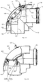
- FIGS. 1 to 11 a first embodiment of a double-tube arch system 1 according to the invention is shown, whereas the FIGS. 12 to 20 show a second embodiment of a double-tube arch system 101 according to the invention.
- Both embodiments of the double-pipe system 1 or 101 each have an outer pipe bend 2 or 102 and an inner pipe bend 3 or 103 surrounded by the outer pipe bend, which is described, for example, with reference to the illustration of FIG Figures 1 and 2 for the first embodiment or the FIGS. 12 and 13 for the second embodiment is apparent.
- FIG. 1 to 11 a first embodiment of a double-tube arch system 1 according to the invention is shown
- FIGS. 12 to 20 show a second embodiment of a double-tube arch system 101 according to the invention.
- Both embodiments of the double-pipe system 1 or 101 each have an outer pipe bend 2 or 102 and an inner pipe bend 3 or 103 surrounded by the outer pipe bend, which is described, for example, with reference to the illustration of FIG Figures 1 and 2 for the first embodiment or the FIGS
- the outer pipe bend 2 includes a first outer pipe bend portion 4 and a second outer pipe bend portion 5 connected to each other via an outer arc portion 6, whereas the inner pipe bend 3 includes a first inner pipe bend portion 7 and a second inner pipe bend portion 8 connected to each other via an inner arc portion 9 are connected.
- the outer pipe bend 102 includes a first outer pipe bend portion 104 and a second outer pipe bend portion 105 connected to each other via an outer arc portion 106
- the inner pipe bend 103 includes a first inner pipe bend portion 107 and a second inner pipe bend portion 108 connected to each other via an inner arc portion 109.
- first outer pipe bend sections 4, 104, the second outer pipe bend sections 5, 105, the first inner pipe bend sections 7, 107 and the second inner pipe bend sections 8, 108 are essentially rectilinear pipe sections that are located on the inner side Knick 10 of the double-tube arch system 1, 101 substantially rectilinear meet, whereas the outer arc portion 6, 106 and the inner arc portion 9, 109 rounded rear side or on the outside bend 11 of the double-tube system 1, 101 or arcuately extending in the lateral section are formed.
- other embodiments are conceivable in which also provided inside a rounding.
- first outer pipe bend portion 4, 104 and the first inner pipe bend portion 7, 107 are arranged concentrically to a first longitudinal axis 12, whereas the second outer pipe bend portion 5, 105 and the second inner pipe bend portion 8, 108 are arranged concentrically to a second longitudinal axis 14.
- first longitudinal axis 12 and the second longitudinal axis 14 are inclined at an angle 15 of 88.5 ° to each other, alternatively, other angles between 87 ° and 89 ° or a right-angled arrangement are possible.
- the inner pipe bend 3, 103 protrudes from the respective mouth edges 16, 17 of the outer pipe bend 2, 102. Furthermore, the inner pipe bend 3, 103 has a longitudinal end formed with a plug-in sleeve 18.
- the plug-in sleeve 18 is in this case formed on the respective second inner pipe bend section 8, 108, wherein a sealing ring 19 is accommodated in it (see, for example, FIG Figures 2 and 3 for the first embodiment and the Figures 13 and 14 for the second embodiment).
- FIG Figures 2 and 3 for the first embodiment and the Figures 13 and 14 for the second embodiment.
- plug-in socket or with push-in sleeves on both pipe bend ends are also conceivable are embodiments without plug-in socket or with push-in sleeves on both pipe bend ends.
- a positive connection 20 for concentric alignment and stable fixation of inner tube sheet 3, 103 and outer tube sheet 2, 102 is a positive connection 20 (see FIGS. 4 and 15 ) are provided in both embodiments, by which the outer tube sheet 2, 102 and the inner tube sheet 3, 103 are connected to each other.
- This positive connection 20 is designed in the manner of a latching connection 21, which will be described below.
- the latching connection 21 in the first embodiment comprises a plurality of pairs of fixing bars 22a, 22b and 23a, 23b, the pair of fixing bars 22a and 22b extending radially from the inner side 24 of the outer tube sheet 2 and toward the first longitudinal axis 12, whereas the other one Pair of fixing webs 23a and 23b extends radially from the inner side 24 of the outer pipe bend 2 and in the direction of the second longitudinal axis 14.
- the longitudinal ends 30, 31 of the fixing webs 22a and 23a and the longitudinal ends 32, 33 of the fixing webs 22b and 23b converge toward each other and are connected to each other in this way (see, for example FIGS. 4 or 7 ), that the fixing webs 22a, 23a and 22b, 23b have an L-shaped configuration.
- the symmetrical configuration of the outer pipe bend 2 has the purpose that the inner pipe bend 3 can be introduced with its Einsteckmuffe 18 in both mouths 16, 17 of the outer pipe bend 2 and connected thereto. Consequently, the flexibility is increased.
- the latching connection 21 furthermore comprises a pair of insertion pockets 25a and 25b which extend radially from the outside 26 of the inner tube bend 3 and in the direction of the first longitudinal axis 12.
- the latching connection 21 comprises a pair of fixing bars 122a, 122b (see, for example, FIG FIG. 19 ) extending radially from the inner side 24 of the outer tube bend 102 and in the direction of the first longitudinal axis 12.
- a pair of fixing webs 122a, 122b is provided in the second embodiment, because it is only possible in this embodiment, to introduce the inner pipe bend 103 via the mouth 16 in the outer pipe bend 102.
- the latching connection 21 comprises a pair of insertion pockets 125a and 125b which extend radially from the outside 26 of the inner tube bend 103 and in the direction of the first longitudinal axis 12.
- a respective fixing web 22a, 22b, 23a, 23b, 122a, 122b is inserted into an associated insertion pocket 25a, 25b, 125a, 125b and is engaged with this form-fitting.
- the fixing land 22a (or the fixing land 23a in the other insertion direction of the inner pipe bend 3) engages with the insertion pocket 25a
- the fixing land 122a engages with the insertion pocket 125a to make the engagement joint 21.
- a respective insertion pocket 25a, 25b and 125a, 125b is U-shaped and has an insertion opening 40 or 140, a guide leg 41 and 141 and a parallel to the guide leg 41 and 141 extending locking leg 42 and 142nd on (see for example FIG. 5 for the first embodiment and FIG. 16 for the second embodiment).
- a hook-shaped projection 43 or 143 is integrally formed. This hook-shaped projection 43 or 143 of each locking leg 42 or 142 engages behind a longitudinal end 30, 32 or 31, 33 or 130, 132 of the associated fixing web 22a, 22b, 23a, 23b, 122a, 122b.
- a respective latching leg 42 or 142 has a greater longitudinal extent along the first longitudinal axis 12 than an associated guide leg 41 or 141.
- the inner pipe bend 3, 103 is thus inserted in both embodiments with its plug-in sleeve 18 first into the mouth 16 of the outer pipe bend 2, 102, wherein when inserting a respective fixing web 22a, 22b, 122a, 122b in an insertion 40th 140 passes an associated insertion pocket 25a, 25b, 125a, 125b and then dips between an associated guide leg 41, 141 and an associated locking leg 42, 142 in the insertion pocket 25a, 25b, 125a, 125b until the respective fixing web 22a, 22b, 122a , 122b is substantially completely received by the insertion pocket 25a, 25b, 125a, 125b, whereby the corresponding hook-shaped projection 43, 143 the longitudinal end 30, 32 or 130, 132 of the fixing web 22a, 22b, 23a,
- At least the hook-shaped projections 43 or 143 of the pockets 25a, 25b, 125a, 125b are elastically formed, so that the latching connection 21 is also canceled and the inner tube sheet 3, 103 of the outer tube sheet 2, 102 can be disassembled.
- the locking connection 21 described above applies to both embodiments shown in the figures, wherein the pairs of fixing webs 22a, 22b, 23a, 23b, 122a, 122b centrally between the first outer pipe bend portion 4, 104 and the second outer pipe bend portion 5, 105 at the outer bow portion 6, 106 are formed.
- each pair of fixing webs 22a, 22b, 23a, 23b, 122a, 122b are arranged diametrically opposite one another on opposite sides of the outer pipe bend 2, 102.
- the paired insertion pockets 25a, 25b, 125a, 125b are formed centrally between the first inner pipe bend portion 7, 107 and the second inner pipe bend portion 8, 108 at the inner bow portion 9, 109, the pairs of insertion pockets 25a, 25b, 125a, 125b are arranged diametrically opposite one another on opposite sides of the inner tube bend 3, 103.
- a secure and non-tiltable form-locking connection 20th ensure between outer pipe bend 2, 102 and inner pipe bend 3, 103, this connection comprising two points of support can still be increased by a support extension 60, 160 which extends radially on the outer side 26 of the inner pipe bend 3, 103.
- the support lug 60, 160 extends in the direction of the second longitudinal axis 14.
- the support lug 60, 160 is formed with respect to the circumference of the inner pipe bend 3, 103 centrally between the pair of insertion pockets 25a, 25b, 125a, 125b on the outer side 26 of the inner pipe bend 3, 103 and supports on the inner surface 24 of the outer pipe bend 2, 102 from.
- the support lug 60, 160 has a bore 61, 161, as for example from the Figures 3 and 14 you can see.
- a screw should the locking connection have weaknesses or be damaged this screw can be used by means of the bore 61, 161 in addition to the locking connection 21 to the strength the connection of outer pipe bend 2, 102 and inner pipe bend 3 to increase.
- a U-shaped holding means 62, 162 is formed on the inner side 24 of the outer tube bend 2, 102 with respect to the support lug 60, 160 in both embodiments (see, for example FIGS. 7 . 8 and 9 for the first embodiment and Figures 18 . 19 and 20 for the second embodiment).
- the U-shaped holding means 62, 162 formed by three webs, which are integrally formed on the inner side 24 of the outer tube sheet 2, 102 and extend there radially.
- the first embodiment has two holding means 62, so that the inner pipe bend 3 with its plug-in sleeve 18 in both mouths of the outer pipe bend 2 can be introduced and the support extension 60 is given a possibility of support by a corresponding holding means 62 ,
- the U-shaped holding means 62, 162 with respect to the circumference of the inner tube sheet 3, 103 is arranged centrally between the paired fixing webs 22a, 22b, 23a, 23b, 122a, 122b and that the support lug 60th , 160 in the assembled state of the double-pipe system 1, 101 between the two legs of the U-shaped holding means 62, 162 is arranged.
- a guide projection 70, 170 is provided which extends on the outside of the inner tube bend 3, 103 extends radially and in the direction of the first longitudinal axis 12.
- the guide lug 70, 170 is formed with a T-shaped head.
- the holding means 62 not used by the supporting lug 60 in the mounted state of the double-pipe system 1 is used by the guide lug 70 as a receiving means.
- the T-shaped head of the guide lug 70 abuts the portion 90 of the U-shaped holding means 62, which is arranged between the two mutually parallel legs 91, 92 of the U-shaped holding means 62 (see, for example Figures 3 .
- a projection 190 is formed on the inner side 24 of the outer tube bend 102, which serves primarily to fix a latch 180 which is intended to fix a cover 181 to the outer tube bend 102, which closes an inspection opening 182 in the outer tube bend 102.
- the holding means 62 which simultaneously correspond to the receiving means, are formed at the transition from the first outer tube arch section 4 to the outer arch section 6 and from the second outer tube arch section 5 to the outer arch section 6, respectively.
- the holding means 162 is at the transition from the first outer tube arc portion 104 is formed to the outer arc portion 106.
- the guide lug 70, 170 is formed with its T-shaped head at the transition from the second inner pipe bend section 8, 108 to the inner curve section 9, 109.
- the second embodiment differs from the first embodiment in that the second embodiment has inspection openings for both pipe bends 102 and 103.
- the inner pipe bend 103 has a circular opening 185.
- Two retaining projections 186 protrude radially from the outside 26 of the inner pipe bend 103.
- the holding projections 186 are arranged diametrically opposite to the circular opening 185 and each provided with a perforation 185 directed and hook-like nose 187 to engage behind the top of a lid inserted into the opening 185 element 188 can.
Landscapes
- Engineering & Computer Science (AREA)
- General Engineering & Computer Science (AREA)
- Mechanical Engineering (AREA)
- Quick-Acting Or Multi-Walled Pipe Joints (AREA)
Claims (15)
- Système de raccord coudé double (1 ; 101) présentant un raccord coudé extérieur (2 ; 102) et un raccord coudé intérieur (3 ; 103) entouré par le raccord coudé extérieur (2 ; 102),
dans lequel le raccord coudé extérieur (2 ; 102) comprend une première partie de raccord coudé extérieur (4 ; 104) et une deuxième partie de raccord coudé extérieur (5 ; 105), lesquelles sont reliées l'une à l'autre par l'intermédiaire d'une partie coudée extérieure (6 ; 106),
dans lequel le raccord coudé intérieur (3 ; 103) comprend une première partie de raccord coudé intérieur (7 ; 107) et une deuxième partie de raccord coudé intérieur (8 ; 108), lesquelles sont reliées l'une à l'autre par l'intermédiaire d'une partie coudée intérieure (9 ; 109),
dans lequel la première partie de raccord coudé extérieur (4 ; 104) et la première partie de raccord coudé intérieur (7 ; 107) sont disposées de manière concentrique à un premier axe longitudinal (12),
dans lequel la deuxième partie de raccord coudé extérieur (5 ; 105) et la deuxième partie de raccord coudé intérieur (8 ; 108) sont disposées de manière concentrique à un deuxième axe longitudinal (14), et
dans lequel le raccord coudé extérieur (2 ; 102) et le raccord coudé intérieur (3 ; 103) sont reliés l'un à l'autre par l'intermédiaire d'une liaison par complémentarité de formes (20),
caractérisé en ce que
la liaison par complémentarité de formes (20) est une liaison d'encliquetage (21), laquelle comprend au moins deux entretoises de fixation (22a, 22b, 23a, 23b ; 122a, 122b) qui s'étendent à partir du côté intérieur (24) du raccord coudé extérieur (2 ; 102) de façon radiale et au moins en direction du premier axe longitudinal (12), et au moins deux poches d'insertion (25a, 25b ; 125a, 125b) qui s'étendent à partir du côté extérieur (26) du raccord coudé intérieur (3 ; 103) de façon radiale et au moins en direction du premier axe longitudinal (12), dans lequel une entretoise de fixation (22a, 22b, 23a, 23b ; 122a, 122b) respective est insérée dans une poche d'insertion (25a, 25b ; 125a, 125b) associée et est en prise avec celle-ci par complémentarité de formes. - Système de raccord coudé double (1 ; 101) selon la revendication 1, caractérisé en ce qu'une poche d'insertion (25a, 25b ; 125a, 125b) respective est réalisée en forme de U avec une ouverture d'insertion (40 ; 140), une branche de guidage (41 ; 141) et une branche d'encliquetage (42 ; 142) s'étendant parallèlement à la branche de guidage (41 ; 141), dans lequel la branche d'encliquetage (42 ; 142) présente une plus grande étendue longitudinale le long du premier axe longitudinal (12) que la branche de guidage (41 ; 141), et dans lequel un prolongement en forme de crochet (43 ; 143) est formé sur l'extrémité libre de la branche d'encliquetage (42 ; 142), lequel saisit par l'arrière une extrémité longitudinale (30, 31, 32, 33 ; 130, 132) de l'entretoise de fixation (22a, 22b, 23a, 23b ; 122a, 122b) associée.
- Système de raccord coudé double (1 ; 101) selon la revendication 1 ou 2, caractérisé en ce que, sur le côté extérieur (26) du raccord coudé intérieur (3 ; 103), au moins un prolongement de support (60 ; 160) s'étend radialement, dans lequel l'au moins un prolongement de support (60 ; 160) est formé par rapport à la périphérie du raccord coudé intérieur (3 ; 103) de manière centrale entre les au moins deux poches d'insertion (25a, 25b ; 125a, 125b) sur le côté extérieur (26) du raccord coudé intérieur (3 ; 103) et est en appui sur la surface intérieure (24) du raccord coudé extérieur (2 ; 102).
- Système de raccord coudé double (1 ; 101) selon la revendication 3, caractérisé en ce que l'au moins un prolongement de support (60 ; 160) s'étend en direction du deuxième axe longitudinal (14).
- Système de raccord coudé double (1 ; 101) selon la revendication 3 ou 4, caractérisé en ce qu'au moins un moyen de retenue (62 ; 162) réalisé en forme de U est formé sur le côté intérieur (24) du raccord coudé extérieur (2 ; 102), lequel est disposé par rapport à la périphérie du raccord coudé intérieur (3 ; 103) de manière centrale entre les au moins deux entretoises de fixation (22a, 22b, 23a, 23b ; 122a, 122b), dans lequel l'au moins un prolongement de support (60 ; 160) est disposé entre les deux branches s'étendant parallèlement entre elles du moyen de retenue (62 ; 162) réalisé en forme de U.
- Système de raccord coudé double (1 ; 101) selon la revendication 3, 4 ou 5, caractérisé en ce que l'au moins un prolongement de support (60 ; 160) présente un alésage (61 ; 161) prévu pour un moyen de vissage pouvant être introduit depuis le côté extérieur du raccord coudé extérieur (2 ; 102).
- Système de raccord coudé double (1 ; 101) selon l'une des revendications précédentes, caractérisé en ce que les au moins deux entretoises de fixation (22a, 22b, 23a, 23b ; 122a, 122b) sont réalisées de manière centrale entre la première partie de raccord coudé extérieur (4 ; 104) et la deuxième partie de raccord coudé extérieur (5 ; 105) sur la partie coudée extérieure (6 ; 106) et que les au moins deux poches d'insertion (25a, 25b ; 125a, 125b) sont réalisées de manière centrale entre la première partie de raccord coudé intérieur (7 ; 107) et la deuxième partie de raccord coudé intérieur (8 ; 108) sur la partie coudée intérieure (9 ; 109).
- Système de raccord coudé double (1 ; 101) selon l'une des revendications précédentes, caractérisé en ce que, sur le côté extérieur (26) du raccord coudé intérieur (3 ; 103), au moins un prolongement de guidage (70 ; 170) s'étend radialement et en direction du premier axe longitudinal (12), dans lequel l'au moins un prolongement de guidage (70 ; 170) est réalisé avec une tête en forme de T.
- Système de raccord coudé double (1 ; 101) selon la revendication 8, caractérisé en ce qu'au moins un moyen de réception (62 ; 162) réalisé en forme de U est formé de manière correspondante à l'au moins un prolongement de guidage (70 ; 170) sur le côté intérieur (24) du raccord coudé extérieur (2 ; 102) de manière à ce que la tête réalisée en forme de T du prolongement de guidage (70 ; 170) est disposée entre les branches s'étendant parallèlement entre elles du moyen de réception (62 ; 162) réalisé en forme de U et qu'au niveau de la partie (90 ; 190) reliant les branches (91, 92) s'étendant parallèlement entre elles du moyen de réception (62 ; 162), un mouvement du raccord coudé intérieur (3 ; 103) arrive en butée de manière bloquante en direction de la partie (90 ; 190) .
- Système de raccord coudé double (1 ; 101) selon la revendication 9, caractérisé en ce que l'au moins un moyen de réception (62 ; 162) est réalisé au niveau de la transition de la deuxième partie de raccord coudé extérieur (5 ; 105) vers la partie coudée extérieure (6 ; 106) et que l'au moins un prolongement de guidage (70 ; 170) est réalisé au niveau de la transition de la deuxième partie de raccord coudé intérieur (8 ; 108) vers la partie coudée intérieure (9 ; 109).
- Système de raccord coudé double (1 ; 101) selon l'une des revendications précédentes, caractérisé en ce que les au moins deux entretoises de fixation (22a, 22b, 23a, 23b ; 122a, 122b) sont disposées de manière à être situées diamétralement entre elles sur des côtés situés en vis-à-vis du raccord coudé extérieur (2 ; 102) et que les au moins deux poches d'insertion (25a, 25b ; 125a, 125b) sont disposées de manière à être situées diamétralement entre elles sur des côtés situés en vis-à-vis du raccord coudé intérieur (3 ; 103) .
- Système de raccord coudé double (1 ; 101) selon l'une des revendications précédentes, caractérisé en ce que le raccord coudé intérieur (3 ; 103) dépasse des bords d'embouchure respectifs (16, 17) du raccord coudé extérieur (2 ; 102).
- Système de raccord double (1 ; 101) selon l'une des revendications précédentes, caractérisé en ce que le premier axe longitudinal (12) et le deuxième axe longitudinal (14) sont disposés sensiblement en angle droit ou de manière inclinée l'un par rapport à l'autre selon un angle (15) compris entre 87° et 89°.
- Système de raccord double (101) selon l'une des revendications précédentes, caractérisé en ce que le raccord coudé intérieur (103) présente une percée circulaire (185), dans lequel au moins deux saillies de retenue (186) dépassent radialement du côté extérieur (26) du raccord coudé intérieur (103), lesquelles sont disposées de manière à être situées diamétralement en vis-à-vis sur la percée circulaire (185) et sont respectivement dotées d'un bec (187) orienté vers la percée (185) et réalisé à la manière d'un crochet, lequel saisit par l'arrière un côté supérieur d'un élément de couvercle (188) placé dans la percée (185).
- Système de raccord double (101) selon l'une des revendications précédentes, caractérisé en ce que le raccord coudé extérieur (102) présente une ouverture de révision (182), laquelle est fermée à l'aide d'un couvercle (181).
Priority Applications (1)
| Application Number | Priority Date | Filing Date | Title |
|---|---|---|---|
| EP16159996.4A EP3217060B1 (fr) | 2016-03-11 | 2016-03-11 | Systeme de raccord coude double |
Applications Claiming Priority (1)
| Application Number | Priority Date | Filing Date | Title |
|---|---|---|---|
| EP16159996.4A EP3217060B1 (fr) | 2016-03-11 | 2016-03-11 | Systeme de raccord coude double |
Publications (2)
| Publication Number | Publication Date |
|---|---|
| EP3217060A1 EP3217060A1 (fr) | 2017-09-13 |
| EP3217060B1 true EP3217060B1 (fr) | 2018-10-24 |
Family
ID=55588067
Family Applications (1)
| Application Number | Title | Priority Date | Filing Date |
|---|---|---|---|
| EP16159996.4A Active EP3217060B1 (fr) | 2016-03-11 | 2016-03-11 | Systeme de raccord coude double |
Country Status (1)
| Country | Link |
|---|---|
| EP (1) | EP3217060B1 (fr) |
Families Citing this family (1)
| Publication number | Priority date | Publication date | Assignee | Title |
|---|---|---|---|---|
| US11982389B2 (en) * | 2022-09-16 | 2024-05-14 | K.D.W. Company Limited | Double containment fittings for connecting double containment tubing |
Family Cites Families (4)
| Publication number | Priority date | Publication date | Assignee | Title |
|---|---|---|---|---|
| US5186502B1 (en) * | 1990-12-11 | 1994-08-30 | Fibercast Co | Double-containment pipe fittings and system |
| IT243274Y1 (it) * | 1997-03-18 | 2002-03-04 | L N Di Natalini Lino & C Srl | Raccordo per tubi concentrici, formato da due gomiti coassiali |
| NL1014637C2 (nl) * | 2000-03-14 | 2001-09-17 | Ubbink Nederland Bv | Bochtstuk voor uitmondingsconstructies. |
| EP1167858B1 (fr) * | 2000-07-01 | 2004-10-06 | Esser -Werke GmbH & Co. KG | Coude de tuyau pour le transport de matières abrasives |
-
2016
- 2016-03-11 EP EP16159996.4A patent/EP3217060B1/fr active Active
Non-Patent Citations (1)
| Title |
|---|
| None * |
Also Published As
| Publication number | Publication date |
|---|---|
| EP3217060A1 (fr) | 2017-09-13 |
Similar Documents
| Publication | Publication Date | Title |
|---|---|---|
| DE102015114696A1 (de) | Halterahmen für Steckverbindermodule | |
| EP3271612B1 (fr) | Chaîne de transport d'énergie pourvu d'un support pour un conduit externe, élément de logement et bride latérale correspondante | |
| WO2006018038A1 (fr) | Couplage | |
| DE4110676A1 (de) | Vorrichtung zum verbinden eines vertikal verlaufenden unten liegenden anschlussstutzens mit einem vertikal verlaufenden darueber befindlichen rohrstueck | |
| DE102020134286A1 (de) | Verbindungshülse | |
| WO2016177864A1 (fr) | Passage de câble/ligne | |
| EP2550855A1 (fr) | Mur d'enceinte avec dispositif de durcissement | |
| EP3601867B1 (fr) | Dispositif de raccordement pour conduites de fluide | |
| DE19519073B4 (de) | Vorrichtung zur Verbindung von Rohrleitungsabschnitten untereinander | |
| DE102014102793B4 (de) | Befestigungselement für einen Stromsensor | |
| EP3064849B1 (fr) | Systeme de distribution, en particulier diffuseur d'air | |
| DE102010026100A1 (de) | Schnellkupplung für Fluidleitungen | |
| DE102008032687B4 (de) | Befestigungsanordnung für wasserdurchflossene Sanitärbauteile | |
| DE10240999B4 (de) | Vorrichtung zum winkligen Verbinden von Montageschienen | |
| DE102019132178A1 (de) | Ventilinsel für eine Hydraulikanordnung und Hydraulikanordnung mit Ventilinsel | |
| EP3561976A1 (fr) | Boîte d'installation | |
| EP3217060A1 (fr) | Systeme de raccord coude double | |
| EP2369215B1 (fr) | Connecteur à fiches | |
| EP2915949A1 (fr) | Outil de forage | |
| DE10234206A1 (de) | Steckverbindung für Sanitärarmaturen | |
| DE102018110444B3 (de) | Installationsdose | |
| DE102010053357A1 (de) | Rohrschelle | |
| DE102017129559B4 (de) | Anschlusskopf für eine Filterkerze, Set mit einem Anschlusskopf sowie Filterkerze | |
| DE202014003187U1 (de) | Fixier- sowie Zentrierelement für wenigstens zwei Rohrpaare von Erdwärmesonden | |
| DE102013016765A1 (de) | Montageelement zur Positionierung einer Betriebsmittelleitung |
Legal Events
| Date | Code | Title | Description |
|---|---|---|---|
| PUAI | Public reference made under article 153(3) epc to a published international application that has entered the european phase |
Free format text: ORIGINAL CODE: 0009012 |
|
| STAA | Information on the status of an ep patent application or granted ep patent |
Free format text: STATUS: THE APPLICATION HAS BEEN PUBLISHED |
|
| AK | Designated contracting states |
Kind code of ref document: A1 Designated state(s): AL AT BE BG CH CY CZ DE DK EE ES FI FR GB GR HR HU IE IS IT LI LT LU LV MC MK MT NL NO PL PT RO RS SE SI SK SM TR |
|
| AX | Request for extension of the european patent |
Extension state: BA ME |
|
| STAA | Information on the status of an ep patent application or granted ep patent |
Free format text: STATUS: REQUEST FOR EXAMINATION WAS MADE |
|
| 17P | Request for examination filed |
Effective date: 20180119 |
|
| RBV | Designated contracting states (corrected) |
Designated state(s): AL AT BE BG CH CY CZ DE DK EE ES FI FR GB GR HR HU IE IS IT LI LT LU LV MC MK MT NL NO PL PT RO RS SE SI SK SM TR |
|
| RIC1 | Information provided on ipc code assigned before grant |
Ipc: F16L 39/00 20060101AFI20180611BHEP Ipc: F16L 9/18 20060101ALI20180611BHEP Ipc: F23J 13/02 20060101ALI20180611BHEP |
|
| GRAP | Despatch of communication of intention to grant a patent |
Free format text: ORIGINAL CODE: EPIDOSNIGR1 |
|
| STAA | Information on the status of an ep patent application or granted ep patent |
Free format text: STATUS: GRANT OF PATENT IS INTENDED |
|
| INTG | Intention to grant announced |
Effective date: 20180727 |
|
| GRAS | Grant fee paid |
Free format text: ORIGINAL CODE: EPIDOSNIGR3 |
|
| GRAA | (expected) grant |
Free format text: ORIGINAL CODE: 0009210 |
|
| STAA | Information on the status of an ep patent application or granted ep patent |
Free format text: STATUS: THE PATENT HAS BEEN GRANTED |
|
| AK | Designated contracting states |
Kind code of ref document: B1 Designated state(s): AL AT BE BG CH CY CZ DE DK EE ES FI FR GB GR HR HU IE IS IT LI LT LU LV MC MK MT NL NO PL PT RO RS SE SI SK SM TR |
|
| REG | Reference to a national code |
Ref country code: CH Ref legal event code: EP |
|
| REG | Reference to a national code |
Ref country code: IE Ref legal event code: FG4D Free format text: LANGUAGE OF EP DOCUMENT: GERMAN |
|
| REG | Reference to a national code |
Ref country code: AT Ref legal event code: REF Ref document number: 1057081 Country of ref document: AT Kind code of ref document: T Effective date: 20181115 |
|
| REG | Reference to a national code |
Ref country code: DE Ref legal event code: R096 Ref document number: 502016002301 Country of ref document: DE |
|
| REG | Reference to a national code |
Ref country code: NL Ref legal event code: FP |
|
| REG | Reference to a national code |
Ref country code: LT Ref legal event code: MG4D |
|
| PG25 | Lapsed in a contracting state [announced via postgrant information from national office to epo] |
Ref country code: IS Free format text: LAPSE BECAUSE OF FAILURE TO SUBMIT A TRANSLATION OF THE DESCRIPTION OR TO PAY THE FEE WITHIN THE PRESCRIBED TIME-LIMIT Effective date: 20190224 Ref country code: FI Free format text: LAPSE BECAUSE OF FAILURE TO SUBMIT A TRANSLATION OF THE DESCRIPTION OR TO PAY THE FEE WITHIN THE PRESCRIBED TIME-LIMIT Effective date: 20181024 Ref country code: NO Free format text: LAPSE BECAUSE OF FAILURE TO SUBMIT A TRANSLATION OF THE DESCRIPTION OR TO PAY THE FEE WITHIN THE PRESCRIBED TIME-LIMIT Effective date: 20190124 Ref country code: ES Free format text: LAPSE BECAUSE OF FAILURE TO SUBMIT A TRANSLATION OF THE DESCRIPTION OR TO PAY THE FEE WITHIN THE PRESCRIBED TIME-LIMIT Effective date: 20181024 Ref country code: LV Free format text: LAPSE BECAUSE OF FAILURE TO SUBMIT A TRANSLATION OF THE DESCRIPTION OR TO PAY THE FEE WITHIN THE PRESCRIBED TIME-LIMIT Effective date: 20181024 Ref country code: LT Free format text: LAPSE BECAUSE OF FAILURE TO SUBMIT A TRANSLATION OF THE DESCRIPTION OR TO PAY THE FEE WITHIN THE PRESCRIBED TIME-LIMIT Effective date: 20181024 Ref country code: PL Free format text: LAPSE BECAUSE OF FAILURE TO SUBMIT A TRANSLATION OF THE DESCRIPTION OR TO PAY THE FEE WITHIN THE PRESCRIBED TIME-LIMIT Effective date: 20181024 Ref country code: BG Free format text: LAPSE BECAUSE OF FAILURE TO SUBMIT A TRANSLATION OF THE DESCRIPTION OR TO PAY THE FEE WITHIN THE PRESCRIBED TIME-LIMIT Effective date: 20190124 Ref country code: HR Free format text: LAPSE BECAUSE OF FAILURE TO SUBMIT A TRANSLATION OF THE DESCRIPTION OR TO PAY THE FEE WITHIN THE PRESCRIBED TIME-LIMIT Effective date: 20181024 |
|
| PG25 | Lapsed in a contracting state [announced via postgrant information from national office to epo] |
Ref country code: PT Free format text: LAPSE BECAUSE OF FAILURE TO SUBMIT A TRANSLATION OF THE DESCRIPTION OR TO PAY THE FEE WITHIN THE PRESCRIBED TIME-LIMIT Effective date: 20190224 Ref country code: AL Free format text: LAPSE BECAUSE OF FAILURE TO SUBMIT A TRANSLATION OF THE DESCRIPTION OR TO PAY THE FEE WITHIN THE PRESCRIBED TIME-LIMIT Effective date: 20181024 Ref country code: RS Free format text: LAPSE BECAUSE OF FAILURE TO SUBMIT A TRANSLATION OF THE DESCRIPTION OR TO PAY THE FEE WITHIN THE PRESCRIBED TIME-LIMIT Effective date: 20181024 Ref country code: GR Free format text: LAPSE BECAUSE OF FAILURE TO SUBMIT A TRANSLATION OF THE DESCRIPTION OR TO PAY THE FEE WITHIN THE PRESCRIBED TIME-LIMIT Effective date: 20190125 Ref country code: SE Free format text: LAPSE BECAUSE OF FAILURE TO SUBMIT A TRANSLATION OF THE DESCRIPTION OR TO PAY THE FEE WITHIN THE PRESCRIBED TIME-LIMIT Effective date: 20181024 |
|
| REG | Reference to a national code |
Ref country code: DE Ref legal event code: R097 Ref document number: 502016002301 Country of ref document: DE |
|
| PG25 | Lapsed in a contracting state [announced via postgrant information from national office to epo] |
Ref country code: CZ Free format text: LAPSE BECAUSE OF FAILURE TO SUBMIT A TRANSLATION OF THE DESCRIPTION OR TO PAY THE FEE WITHIN THE PRESCRIBED TIME-LIMIT Effective date: 20181024 Ref country code: DK Free format text: LAPSE BECAUSE OF FAILURE TO SUBMIT A TRANSLATION OF THE DESCRIPTION OR TO PAY THE FEE WITHIN THE PRESCRIBED TIME-LIMIT Effective date: 20181024 |
|
| PG25 | Lapsed in a contracting state [announced via postgrant information from national office to epo] |
Ref country code: SM Free format text: LAPSE BECAUSE OF FAILURE TO SUBMIT A TRANSLATION OF THE DESCRIPTION OR TO PAY THE FEE WITHIN THE PRESCRIBED TIME-LIMIT Effective date: 20181024 Ref country code: EE Free format text: LAPSE BECAUSE OF FAILURE TO SUBMIT A TRANSLATION OF THE DESCRIPTION OR TO PAY THE FEE WITHIN THE PRESCRIBED TIME-LIMIT Effective date: 20181024 Ref country code: SK Free format text: LAPSE BECAUSE OF FAILURE TO SUBMIT A TRANSLATION OF THE DESCRIPTION OR TO PAY THE FEE WITHIN THE PRESCRIBED TIME-LIMIT Effective date: 20181024 Ref country code: RO Free format text: LAPSE BECAUSE OF FAILURE TO SUBMIT A TRANSLATION OF THE DESCRIPTION OR TO PAY THE FEE WITHIN THE PRESCRIBED TIME-LIMIT Effective date: 20181024 |
|
| PLBE | No opposition filed within time limit |
Free format text: ORIGINAL CODE: 0009261 |
|
| STAA | Information on the status of an ep patent application or granted ep patent |
Free format text: STATUS: NO OPPOSITION FILED WITHIN TIME LIMIT |
|
| 26N | No opposition filed |
Effective date: 20190725 |
|
| PG25 | Lapsed in a contracting state [announced via postgrant information from national office to epo] |
Ref country code: MC Free format text: LAPSE BECAUSE OF FAILURE TO SUBMIT A TRANSLATION OF THE DESCRIPTION OR TO PAY THE FEE WITHIN THE PRESCRIBED TIME-LIMIT Effective date: 20181024 Ref country code: SI Free format text: LAPSE BECAUSE OF FAILURE TO SUBMIT A TRANSLATION OF THE DESCRIPTION OR TO PAY THE FEE WITHIN THE PRESCRIBED TIME-LIMIT Effective date: 20181024 |
|
| REG | Reference to a national code |
Ref country code: CH Ref legal event code: PL |
|
| PG25 | Lapsed in a contracting state [announced via postgrant information from national office to epo] |
Ref country code: LU Free format text: LAPSE BECAUSE OF NON-PAYMENT OF DUE FEES Effective date: 20190311 |
|
| PG25 | Lapsed in a contracting state [announced via postgrant information from national office to epo] |
Ref country code: LI Free format text: LAPSE BECAUSE OF NON-PAYMENT OF DUE FEES Effective date: 20190331 Ref country code: IE Free format text: LAPSE BECAUSE OF NON-PAYMENT OF DUE FEES Effective date: 20190311 Ref country code: CH Free format text: LAPSE BECAUSE OF NON-PAYMENT OF DUE FEES Effective date: 20190331 |
|
| PG25 | Lapsed in a contracting state [announced via postgrant information from national office to epo] |
Ref country code: TR Free format text: LAPSE BECAUSE OF FAILURE TO SUBMIT A TRANSLATION OF THE DESCRIPTION OR TO PAY THE FEE WITHIN THE PRESCRIBED TIME-LIMIT Effective date: 20181024 |
|
| PG25 | Lapsed in a contracting state [announced via postgrant information from national office to epo] |
Ref country code: MT Free format text: LAPSE BECAUSE OF FAILURE TO SUBMIT A TRANSLATION OF THE DESCRIPTION OR TO PAY THE FEE WITHIN THE PRESCRIBED TIME-LIMIT Effective date: 20181024 |
|
| PG25 | Lapsed in a contracting state [announced via postgrant information from national office to epo] |
Ref country code: CY Free format text: LAPSE BECAUSE OF FAILURE TO SUBMIT A TRANSLATION OF THE DESCRIPTION OR TO PAY THE FEE WITHIN THE PRESCRIBED TIME-LIMIT Effective date: 20181024 |
|
| PG25 | Lapsed in a contracting state [announced via postgrant information from national office to epo] |
Ref country code: HU Free format text: LAPSE BECAUSE OF FAILURE TO SUBMIT A TRANSLATION OF THE DESCRIPTION OR TO PAY THE FEE WITHIN THE PRESCRIBED TIME-LIMIT; INVALID AB INITIO Effective date: 20160311 |
|
| REG | Reference to a national code |
Ref country code: AT Ref legal event code: MM01 Ref document number: 1057081 Country of ref document: AT Kind code of ref document: T Effective date: 20210311 |
|
| PG25 | Lapsed in a contracting state [announced via postgrant information from national office to epo] |
Ref country code: MK Free format text: LAPSE BECAUSE OF FAILURE TO SUBMIT A TRANSLATION OF THE DESCRIPTION OR TO PAY THE FEE WITHIN THE PRESCRIBED TIME-LIMIT Effective date: 20181024 |
|
| PG25 | Lapsed in a contracting state [announced via postgrant information from national office to epo] |
Ref country code: AT Free format text: LAPSE BECAUSE OF NON-PAYMENT OF DUE FEES Effective date: 20210311 |
|
| PGFP | Annual fee paid to national office [announced via postgrant information from national office to epo] |
Ref country code: GB Payment date: 20260324 Year of fee payment: 11 |
|
| PGFP | Annual fee paid to national office [announced via postgrant information from national office to epo] |
Ref country code: DE Payment date: 20260331 Year of fee payment: 11 |
|
| PGFP | Annual fee paid to national office [announced via postgrant information from national office to epo] |
Ref country code: BE Payment date: 20260319 Year of fee payment: 11 Ref country code: IT Payment date: 20260324 Year of fee payment: 11 |
|
| PGFP | Annual fee paid to national office [announced via postgrant information from national office to epo] |
Ref country code: NL Payment date: 20260319 Year of fee payment: 11 |
|
| PGFP | Annual fee paid to national office [announced via postgrant information from national office to epo] |
Ref country code: FR Payment date: 20260320 Year of fee payment: 11 |