EP3217227B1 - Mecanisme regulateur d'horlogerie a echappement magnetique optimise - Google Patents
Mecanisme regulateur d'horlogerie a echappement magnetique optimise Download PDFInfo
- Publication number
- EP3217227B1 EP3217227B1 EP16159796.8A EP16159796A EP3217227B1 EP 3217227 B1 EP3217227 B1 EP 3217227B1 EP 16159796 A EP16159796 A EP 16159796A EP 3217227 B1 EP3217227 B1 EP 3217227B1
- Authority
- EP
- European Patent Office
- Prior art keywords
- magnetic
- torque
- wheel set
- escapement
- regulating mechanism
- Prior art date
- Legal status (The legal status is an assumption and is not a legal conclusion. Google has not performed a legal analysis and makes no representation as to the accuracy of the status listed.)
- Active
Links
Images


Classifications
-
- G—PHYSICS
- G04—HOROLOGY
- G04C—ELECTROMECHANICAL CLOCKS OR WATCHES
- G04C5/00—Electric or magnetic means for converting oscillatory to rotary motion in time-pieces, i.e. electric or magnetic escapements
- G04C5/005—Magnetic or electromagnetic means
-
- G—PHYSICS
- G04—HOROLOGY
- G04B—MECHANICALLY-DRIVEN CLOCKS OR WATCHES; MECHANICAL PARTS OF CLOCKS OR WATCHES IN GENERAL; TIME PIECES USING THE POSITION OF THE SUN, MOON OR STARS
- G04B15/00—Escapements
- G04B15/14—Component parts or constructional details, e.g. construction of the lever or the escape wheel
-
- G—PHYSICS
- G04—HOROLOGY
- G04B—MECHANICALLY-DRIVEN CLOCKS OR WATCHES; MECHANICAL PARTS OF CLOCKS OR WATCHES IN GENERAL; TIME PIECES USING THE POSITION OF THE SUN, MOON OR STARS
- G04B1/00—Driving mechanisms
- G04B1/10—Driving mechanisms with mainspring
- G04B1/22—Compensation of changes in the motive power of the mainspring
-
- G—PHYSICS
- G04—HOROLOGY
- G04B—MECHANICALLY-DRIVEN CLOCKS OR WATCHES; MECHANICAL PARTS OF CLOCKS OR WATCHES IN GENERAL; TIME PIECES USING THE POSITION OF THE SUN, MOON OR STARS
- G04B13/00—Gearwork
- G04B13/001—Gearwork with the choice of adjustable or varying transmission ratio
-
- G—PHYSICS
- G04—HOROLOGY
- G04B—MECHANICALLY-DRIVEN CLOCKS OR WATCHES; MECHANICAL PARTS OF CLOCKS OR WATCHES IN GENERAL; TIME PIECES USING THE POSITION OF THE SUN, MOON OR STARS
- G04B17/00—Mechanisms for stabilising frequency
- G04B17/20—Compensation of mechanisms for stabilising frequency
- G04B17/26—Compensation of mechanisms for stabilising frequency for the effect of variations of the impulses
-
- G—PHYSICS
- G04—HOROLOGY
- G04B—MECHANICALLY-DRIVEN CLOCKS OR WATCHES; MECHANICAL PARTS OF CLOCKS OR WATCHES IN GENERAL; TIME PIECES USING THE POSITION OF THE SUN, MOON OR STARS
- G04B17/00—Mechanisms for stabilising frequency
- G04B17/32—Component parts or constructional details, e.g. collet, stud, virole or piton
-
- G—PHYSICS
- G04—HOROLOGY
- G04C—ELECTROMECHANICAL CLOCKS OR WATCHES
- G04C3/00—Electromechanical clocks or watches independent of other time-pieces and in which the movement is maintained by electric means
- G04C3/04—Electromechanical clocks or watches independent of other time-pieces and in which the movement is maintained by electric means wherein movement is regulated by a balance
- G04C3/06—Electromechanical clocks or watches independent of other time-pieces and in which the movement is maintained by electric means wherein movement is regulated by a balance using electromagnetic coupling between electric power source and balance
-
- G—PHYSICS
- G04—HOROLOGY
- G04C—ELECTROMECHANICAL CLOCKS OR WATCHES
- G04C3/00—Electromechanical clocks or watches independent of other time-pieces and in which the movement is maintained by electric means
- G04C3/04—Electromechanical clocks or watches independent of other time-pieces and in which the movement is maintained by electric means wherein movement is regulated by a balance
- G04C3/06—Electromechanical clocks or watches independent of other time-pieces and in which the movement is maintained by electric means wherein movement is regulated by a balance using electromagnetic coupling between electric power source and balance
- G04C3/061—Electromechanical clocks or watches independent of other time-pieces and in which the movement is maintained by electric means wherein movement is regulated by a balance using electromagnetic coupling between electric power source and balance the balance controlling contacts and mechanically driving the gear-train
-
- G—PHYSICS
- G04—HOROLOGY
- G04C—ELECTROMECHANICAL CLOCKS OR WATCHES
- G04C3/00—Electromechanical clocks or watches independent of other time-pieces and in which the movement is maintained by electric means
- G04C3/04—Electromechanical clocks or watches independent of other time-pieces and in which the movement is maintained by electric means wherein movement is regulated by a balance
- G04C3/06—Electromechanical clocks or watches independent of other time-pieces and in which the movement is maintained by electric means wherein movement is regulated by a balance using electromagnetic coupling between electric power source and balance
- G04C3/062—Electromechanical clocks or watches independent of other time-pieces and in which the movement is maintained by electric means wherein movement is regulated by a balance using electromagnetic coupling between electric power source and balance the balance controlling contacts, the gear-train or several gear-trains being driven electro-magnetically thereby
-
- G—PHYSICS
- G04—HOROLOGY
- G04C—ELECTROMECHANICAL CLOCKS OR WATCHES
- G04C3/00—Electromechanical clocks or watches independent of other time-pieces and in which the movement is maintained by electric means
- G04C3/04—Electromechanical clocks or watches independent of other time-pieces and in which the movement is maintained by electric means wherein movement is regulated by a balance
- G04C3/06—Electromechanical clocks or watches independent of other time-pieces and in which the movement is maintained by electric means wherein movement is regulated by a balance using electromagnetic coupling between electric power source and balance
- G04C3/063—Electromechanical clocks or watches independent of other time-pieces and in which the movement is maintained by electric means wherein movement is regulated by a balance using electromagnetic coupling between electric power source and balance the balance controlling contacts, the balance driving electro-magnet simultaneously driving the gear-train
-
- G—PHYSICS
- G04—HOROLOGY
- G04C—ELECTROMECHANICAL CLOCKS OR WATCHES
- G04C3/00—Electromechanical clocks or watches independent of other time-pieces and in which the movement is maintained by electric means
- G04C3/04—Electromechanical clocks or watches independent of other time-pieces and in which the movement is maintained by electric means wherein movement is regulated by a balance
- G04C3/06—Electromechanical clocks or watches independent of other time-pieces and in which the movement is maintained by electric means wherein movement is regulated by a balance using electromagnetic coupling between electric power source and balance
- G04C3/064—Electromechanical clocks or watches independent of other time-pieces and in which the movement is maintained by electric means wherein movement is regulated by a balance using electromagnetic coupling between electric power source and balance the balance controlling indirectly, i.e. without mechanical connection, contacts, e.g. by magnetic or optic means
-
- G—PHYSICS
- G04—HOROLOGY
- G04C—ELECTROMECHANICAL CLOCKS OR WATCHES
- G04C3/00—Electromechanical clocks or watches independent of other time-pieces and in which the movement is maintained by electric means
- G04C3/04—Electromechanical clocks or watches independent of other time-pieces and in which the movement is maintained by electric means wherein movement is regulated by a balance
- G04C3/06—Electromechanical clocks or watches independent of other time-pieces and in which the movement is maintained by electric means wherein movement is regulated by a balance using electromagnetic coupling between electric power source and balance
- G04C3/065—Electromechanical clocks or watches independent of other time-pieces and in which the movement is maintained by electric means wherein movement is regulated by a balance using electromagnetic coupling between electric power source and balance the balance controlling gear-train by means of static switches, e.g. transistor circuits
Definitions
- the invention relates to a clockwork mechanism with magnetic escapement comprising energy storage means arranged to deliver energy in the form of an output torque, through a transmission train, to a mobile device.
- magnetic escapement forming a magnetic escape mechanism with a resonator mobile subjected to the torque of a return means, said magnetic escapement mobile cooperating with said resonator mobile, either directly or through a magnetic retainer, said magnetic escapement mechanism being arranged to operate when said magnetic escapement mobile receives a torque greater than or equal to a maintenance torque specific to said magnetic exhaust mechanism.
- the invention also relates to a watch movement comprising such a regulating mechanism.
- the invention also relates to a watch comprising such a clockwork movement.
- the invention relates to the field of watchmaking time control mechanisms, and more particularly the field effect escapement, non-contact or attenuated contact, magnetic or electrostatic type.
- a traditional Swiss anchor escapement has a performance typically of 35% or even 40% at best.
- the interaction between the escape wheel and the anchor in the usual case of steel teeth on ruby pallets, generates considerable friction, and adversely affects the efficiency of the escapement.
- the efficiency is intrinsically related to the level of torque provided by the barrel, due to the design of the magnetic anchor escapement. Indeed, it is an escapement with constant force, that is to say that it theoretically always provides the same energy to the resonator. A variable part of energy excess is dissipated in the rebounds of the magnetic escape wheel. The higher the input torque to the escape wheel, the greater the total power delivered by the barrel, which makes the magnetic escapement wheel bounce longer. This phenomenon results in a decrease in the efficiency of the exhaust when the torque at the escape wheel is high.
- the document EP2911015 in the name of SWATCH GROUP RESEARCH & DEVELOPMENT LTD describes a clockwork escapement mechanism comprising a retainer between a resonator on the one hand and two exhaust mobiles each subjected to a torque.
- Each escape mobile comprises a magnetized or ferromagnetic track according to a period.
- the stopper comprises at least one polar mass, magnetized or ferromagnetic, movable transversely with respect to the scrolling of a surface of the track.
- the polar mass or the track creates a magnetic field between the polar mass and the surface.
- the polar mass is opposed to a magnetic field barrier on the track just before each transverse movement of the stop controlled by the periodic action of the resonator.
- the escape mobiles are each arranged to cooperate alternately with the stop, and are linked to each other by a direct kinematic link.
- the document CH706209 in the name of MONTRES ROMAIN GAUTHIER SA describes a watch movement comprising at least one barrel and a gear train to transmit the energy of the barrel to other elements of the movement.
- the gear train comprising a gearbox with a first transmission ratio to 1, a torque compensation system with a cam downstream of the gearbox to compensate for the torque variation provided by the barrel according to its state of tension of the barrel, and a system of gear with a second transmission ratio greater than 1 to drive these other elements of the movement.
- the torque compensation system comprises a chain arranged to wind on less than one turn or unroll around the cam according to the state of tension of the barrel.
- the document EP1914604 in the name of GIRARD PERREGAUX SA describes a movement comprising a power source having a variable output torque according to its state of charge, intended to maintain the oscillatory movement of a mechanical oscillator through a finishing gear comprising a compensation device, the latter having an input kinematically connected to the power source and an output kinematically connected to the mechanical oscillator, and being arranged to transmit a substantially constant torque to the mechanical oscillator regardless of the state of charge of the energy source.
- This compensation device comprises a cam having a periphery, of variable radius, extending substantially in a plane, the variations of the radius of the cam being a function of those of the output torque of the energy source, and further comprises a mechanism intermediate link arrangement arranged to provide a kinematic connection substantially without sliding between the periphery of the cam and the finishing train.
- the invention proposes to optimize the use of the energy of the energy source, in particular a cylinder, by operating a magnetic exhaust mechanism as close as possible to the value of the minimum maintenance torque for ensure the operation, and where the yield is the highest. It is further proposed to maintain this constant minimum torque as long as possible, using a mechanism for regulating the torque entering the exhaust cell, in particular by using a rocket-chain type transmission.
- the rocket Since Leonardo da Vinci around 1540, the rocket is known to regulate the driving force transmitted to the wheel, and to remedy the problem of torque loss of a traditional barrel: it is therefore usually used in the torque field as high as possible, to compensate for power loss by increasing torque.
- the invention retains, from the usual use of a chain rocket, only its ability to deliver a substantially constant torque.
- the torque control mechanism is advantageously combined with a multiplier transmission to lower the torque level from the energy source, so that, at the beginning of disarming, the level of the torque supplied to the mobile of exhaust is equal to or slightly greater than the value of the maintenance torque of the magnetic exhaust.
- the level of torque supplied to the mobile escapement remained the same.
- the invention relates to a clock control mechanism according to claim 1.
- the invention also relates to a watch movement comprising such a regulating mechanism.
- the invention also relates to a watch comprising such a movement.
- the invention relates to the field of watchmaking time control mechanisms, and more particularly the field effect escapement, non-contact or attenuated contact, magnetic or electrostatic type.
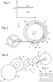
- the Figures 2 and 3 are graphs illustrating the decrease in the efficiency of a magnetic escapement during the increase of the torque applied to the escapement vehicle, generally an escape wheel.
- the figure 2 shows, in ordinate the losses, and in abscissa the torque applied to the mobile of exhaust. It illustrates the channels of absolute losses in a traditional magnetic escapement, where only the losses pR due to the rebounds of the mobile of escape, in particular a magnetic escape wheel, vary when the torque varies. These rebounds consume unusable excess energy, dissipated in the air and in the pivots.
- the upper curve PTF illustrates the total power supplied, which is the sum of the power dissipated by the PDR resonator which is at a constant level, which is the advantage of a magnetic or electrostatic exhaust, losses by pCF shocks and friction (which are consistent when the escapement mechanism includes a stopper such as an anchor or the like), and rebound losses pR, which represent the excess energy consumption, which is inefficient.
- the torque level applied to the tail rotor which is necessary for the operation of the system, is the CE maintenance torque, at which the rebound losses are minimal or zero; the maximum torque level CMAX depends on the power source and the gear train that transmits the energy to the mobile escape.
- the figure 3 shows, on the ordinate, the yield ⁇ , and on the abscissa the torque applied to the escapement mobile. It illustrates the relative loss channels in the same traditional magnetic exhaust: the exhaust efficiency is low at a level pMIN when the torque is high at the CMAX value, and it is raised to a pMAX level when the torque is at the CE value.
- the invention therefore proposes to control the losses, and to avoid energy waste, by limiting rebounds or canceling them completely. For this purpose, it is a question of subjecting the escape wheel to a constant torque, of value at least equal to the maintenance torque CE.
- the figure 4 shows the time constancy of the p performance at the pMAX value.
- the invention is here described in a particular, nonlimiting mode, which is that of a magnetic escapement. It can be implemented in an electrostatic mode, with reference to the document EP13199427 cited above.
- the invention can equally well be implemented in a variant without a stop, with a direct interaction between an escapement wheel and a rocker or the like, described in particular in the document EP2889704 in the name of Nivarox-FAR SA.
- the figure 1 shows a non-limiting example of construction of a watch mechanism 1 regulator comprising a magnetic anchor escapement mechanism 10, optimized according to the invention.
- the invention combines the advantages of a field effect escapement, in particular a magnetic anchor escapement in the variant illustrated by the figures, which is a constant-force mechanism with regard to the resonator mobile, typically a pendulum , and the advantages of a torque control mechanism. More particularly, the transmission of the torque of a power source 2, in particular but not limited to at least one cylinder 20, by a constant torque system, for example a chain rocket, guarantees an almost exhaust torque. constant.
- the torque value CE supplied to the escapement mobile must be chosen low, so that the exhaust has its highest efficiency, of the order of 60% to 70%.
- the invention relates to a magnetic escapement clock control mechanism 1 comprising a power storage means 2 arranged to deliver energy in the form of an output torque CS, through a transmission train 3, to a magnetic escape wheel 4.
- This magnetic escape wheel 4 here illustrated in the form of a magnetic escape wheel, forms a magnetic exhaust mechanism 10 with a resonator wheel 5 subjected to the torque of a return means 6, here illustrated respectively in the form of a balance and a hairspring.
- the magnetic escapement mobile 4 cooperates with the resonator mobile 5, either directly or through a magnetic retainer 7 here illustrated in the form of a magnetic anchor.
- the magnetic exhaust mechanism 10 is arranged to operate when the magnetic escapement mobile 4 receives a torque greater than or equal to a maintenance torque CE specific to the magnetic exhaust mechanism 10.
- the transmission train 3 comprises a torque control means 30, which is arranged to deliver to the magnetic escape wheel 4 a constant torque of between 1.0 and 2.0 times the maintenance torque CE, more particularly between 1.0 and 1.5 times the CE maintenance torque, more particularly between 1.0 and 1.2 times the CE maintenance torque, and as close as possible to this CE maintenance torque, depending on the torque-consuming complications, and the structure of the gear train.
- This pair corresponds to self-starting and canceling rebounds.
- the invention also relates to the variant with an electrostatic exhaust, which is not described in detail, and that the skilled person will implement with reference to the documents cited.
- the torque control means 30 comprises a fuse 8 of continuously variable section, which is a chain 9 wound by a drum 21 driven directly or indirectly by the energy storage means 2.
- the energy storage means 2 comprises at least one barrel 20.
- the invention then optimally uses the entire energy of the barrel, which no longer rotates at a constant speed, since its instantaneous tangential speed depends on the radius instantaneous winding of the chain 9 on the rocket 8.
- the transmission train 3 comprises a multiplier gear train 31 arranged to transform the output torque CS into a lower intermediate torque CI, at the input of the torque control means 30.
- the magnetic escapement mechanism 10 comprises a magnetic retainer 7 between the magnetic escapement mobile 4 and the resonator mobile 5.
- This magnetic escape mobile 4 comprises at least one magnetized or ferromagnetic track 40, with a scrolling period. PD according to which its magnetic characteristics are repeated.
- the stopper 7 comprises at least one polar mass 70 magnetized or ferromagnetic, this polar mass 70 being mobile in a transverse direction DT relative to the direction of travel DD of at least one element of a surface 41 of the track 40.
- At least the polar mass 70, or the track 40 creates a magnetic field in a gap 5 between the at least one polar mass 70 and the at least one surface 41, this polar mass 70 is opposite a magnetic field barrier 42 on the track 40, just before each transversal movement of the stop 7 controlled by the action periodic of the resonator mobile 5.
- the invention also relates to a watch movement 100 comprising such a regulating mechanism 1.
- the invention also relates to a watch 1000 comprising such a movement 100.
- the high value of the efficiency which has become constant, makes it possible to increase the power reserve by more than 50% compared with a traditional Swiss anchor configuration (mechanical or magnetic), for a cylinder, a resonator and a regulating power. given.
- the invention combines the regularity of clean operation field effect exhaust mechanism, including magnetic, with a notable energy saving.
Landscapes
- Physics & Mathematics (AREA)
- General Physics & Mathematics (AREA)
- Electromagnetism (AREA)
- Engineering & Computer Science (AREA)
- Power Engineering (AREA)
- Gears, Cams (AREA)
- Electromechanical Clocks (AREA)
- Electric Clocks (AREA)
Description
- L'invention concerne un mécanisme régulateur d'horlogerie à échappement magnétique comportant un moyen de stockage d'énergie agencé pour délivrer de l'énergie sous forme d'un couple de sortie, au travers d'un rouage de transmission, à un mobile d'échappement magnétique formant un mécanisme d'échappement magnétique avec un mobile de résonateur soumis au couple d'un moyen de rappel, ledit mobile d'échappement magnétique coopérant avec ledit mobile de résonateur, soit directement, soit au travers d'un arrêtoir magnétique, ledit mécanisme d'échappement magnétique étant agencé pour fonctionner quand ledit mobile d'échappement magnétique reçoit un couple supérieur ou égal à un couple d'entretien propre audit mécanisme d'échappement magnétique.
- L'invention concerne encore un mouvement d'horlogerie comportant un tel mécanisme régulateur.
- L'invention concerne encore une montre comportant un tel mouvement d'horlogerie.
- L'invention concerne le domaine des mécanismes régulateurs d'horlogerie, et plus particulièrement des mécanismes d'échappement à effet de champ, sans contact ou à contact atténué, de type magnétique ou électrostatique.
- Un mécanisme d'échappement à ancre suisse traditionnel possède un rendement de typiquement 35%, voire 40% au mieux. Dans un tel échappement, l'interaction entre la roue d'échappement et l'ancre, dans le cas usuel de dents en acier sur palettes en rubis, génère un frottement considérable, et péjore le rendement de l'échappement.
- Le document
EP13199427 - Toutefois, le rendement est intrinsèquement lié au niveau du couple fourni par le barillet, du fait de la conception de l'échappement à ancre magnétique. En effet, c'est un échappement à force constante, c'est-à-dire qu'il fournit théoriquement toujours la même énergie au résonateur. Une part variable d'énergie excédentaire est dissipée dans les rebonds de la roue d'échappement magnétique. Plus le couple d'entrée à la roue d'échappement est élevé, plus la puissance totale fournie par le barillet est élevée, ce qui fait rebondir la roue d'échappement magnétique plus longtemps. Ce phénomène a pour conséquence une diminution du rendement de l'échappement lorsque le couple à la roue d'échappement est élevé.
- A couple faible, la part des rebonds de la roue est faible. Le rendement de l'échappement est élevé, bien supérieur à celui d'un échappement à ancre suisse traditionnel.
- A couple élevé, la part des rebonds de la roue est élevée. Le rendement de l'échappement est moindre qu'à couple faible, et revient à un niveau comparable à celui d'un échappement à ancre suisse traditionnel.
- Le document
EP2911015 au nom de SWATCH GROUP RESEARCH & DEVELOPMENT LTD décrit un mécanisme d'échappement d'horlogerie comportant un arrêtoir entre d'une part un résonateur, et d'autre part deux mobiles d'échappement chacun soumis à un couple. Chaque mobile d'échappement comporte une piste magnétisée ou ferromagnétique selon une période. L'arrêtoir comporte au moins une masse polaire, magnétisée ou ferromagnétique, mobile transversalement par rapport au défilement d'une surface de la piste. La masse polaire ou la piste crée un champ magnétique entre la masse polaire et la surface. La masse polaire est opposée à une barrière de champ magnétique sur la piste juste avant chaque mouvement transversal de l'arrêtoir commandé par l'action périodique du résonateur. Les mobiles d'échappement sont chacun agencé pour coopérer alternativement avec l'arrêtoir, et sont liés l'un à l'autre par une liaison cinématique directe. - Le document
CH706209 - Le document
EP1914604 au nom de GIRARD PERREGAUX SA décrit un mouvement comprenant une source d'énergie présentant un couple de sortie variable en fonction de son état de charge, destinée à entretenir le mouvement oscillant d'un oscillateur mécanique par le biais d'un rouage de finissage comprenant un dispositif de compensation, ce dernier présentant une entrée reliée cinématiquement à la source d'énergie et une sortie reliée cinématiquement à l'oscillateur mécanique, et étant agencé de manière à transmettre un couple sensiblement constant à l'oscillateur mécanique quel que soit l'état de charge de la source d'énergie. Ce dispositif de compensation comporte une came présentant une périphérie, de rayon variable, s'étendant sensiblement dans un plan , les variations du rayon de la came étant fonction de celles du couple de sortie de la source d'énergie, et comporte encore un mécanisme de liaison intermédiaire agencé de manière à assurer une liaison cinématique sensiblement sans glissement entre la périphérie de la came et le rouage de finissage. - L'invention se propose d'optimiser l'utilisation de l'énergie de la source d'énergie, notamment d'un barillet, en faisant travailler un mécanisme d'échappement magnétique au plus proche de la valeur du couple d'entretien minimal pour assurer le fonctionnement, et où le rendement est le plus élevé. Elle se propose, encore, de maintenir ce couple minimum constant le plus longtemps possible, à l'aide d'un mécanisme de régulation du couple entrant sur le mobile d'échappement, notamment en utilisant une transmission de type fusée-chaîne.
- Depuis Léonard de Vinci vers 1540, la fusée est connue pour régulariser la force motrice transmise au rouage, et pour remédier au problème de perte de couple d'un barillet traditionnel: elle est donc usuellement utilisée dans le domaine de couple le plus haut possible, pour compenser la perte de puissance par l'augmentation de couple.
- L'invention ne retient, de l'utilisation usuelle d'une fusée-chaîne, que sa capacité à délivrer un couple sensiblement constant. Le mécanisme de régulation du couple se conjugue, avantageusement, avec une transmission multiplicatrice pour abaisser le niveau de couple en provenance de la source d'énergie, de façon à ce que, en début de désarmage, le niveau du couple fourni au mobile d'échappement soit égal ou légèrement supérieur à la valeur du couple d'entretien de l'échappement magnétique. Bien sûr, du fait de la régulation du couple, en fin de désarmage de la source d'énergie, le niveau du couple fourni au mobile d'échappement est resté le même.
- A cet effet, l'invention concerne un mécanisme régulateur d'horlogerie selon la revendication 1.
- L'invention concerne encore un mouvement d'horlogerie comportant un tel mécanisme régulateur.
- L'invention concerne encore une montre comportant un tel mouvement.
- D'autres caractéristiques et avantages de l'invention apparaîtront à la lecture de la description détaillée qui va suivre, en référence aux dessins annexés, où :
- la
figure 1 représente, de façon schématisée, et en perspective, un mécanisme régulateur d'horlogerie avec mécanisme d'échappement à ancre magnétique optimisé selon l'invention par l'implantation d'une transmission à fusée-chaîne ; - les
figures 2 et 3 sont des graphiques illustrant la diminution du rendement d'un échappement magnétique lorsque le couple est élevé: lafigure 2 montre les canaux de pertes absolus dans un échappement magnétique traditionnel, où seules les pertes dues aux rebonds de la roue d'échappement magnétique varient lorsque le couple varie, et lafigure 3 montre les canaux de pertes relatifs dans un échappement magnétique traditionnel: le rendement de l'échappement est faible lorsque le couple est élevé, et il est élevé lorsque le couple est faible ; - la
figure 4 est un graphique illustrant la constance du rendement dans le temps pour un mécanisme régulateur selon l'invention ; - la
figure 5 représente, de façon schématisée et en plan, un exemple non limitatif de mécanisme d'échappement magnétique intégré dans un tel mécanisme régulateur selon l'invention ; - la
figure 6 représente, de façon schématisée et en plan, un exemple non limitatif de rouage selon l'invention ;- la
figure 7 est un schéma-blocs représentant une montre comportant un mouvement équipé d'un tel mécanisme d'échappement à ancre magnétique optimisé ; - la
figure 8 représente, de façon schématisée, et en perspective, une telle montre.
- la
- L'invention concerne le domaine des mécanismes régulateurs d'horlogerie, et plus particulièrement des mécanismes d'échappement à effet de champ, sans contact ou à contact atténué, de type magnétique ou électrostatique.
- Les
figures 2 et 3 sont des graphiques illustrant la diminution du rendement d'un échappement magnétique lors de l'élévation du couple appliqué au mobile d'échappement, en général une roue d'échappement. - La
figure 2 montre, en ordonnée les pertes, et en abscisse le couple appliqué au mobile d'échappement. Elle illustre les canaux de pertes absolus dans un échappement magnétique traditionnel, où seules les pertes pR dues aux rebonds du mobile d'échappement, notamment une roue d'échappement magnétique, varient lorsque le couple varie. Ces rebonds consomment une énergie excédentaire inutilisable, dissipée dans l'air et dans les pivots. La courbe supérieure PTF illustre la puissance totale fournie, qui est le cumul de la puissance dissipée par le résonateur PDR qui est à un niveau constant, ce qui est l'avantage d'un échappement magnétique ou électrostatique, des pertes par chocs et frottements pCF (qui sont conséquentes quand le mécanisme d'échappement comporte un arrêtoir tel qu'une ancre ou similaire), et les pertes par rebond pR, qui représentent la consommation d'énergie excédentaire, qui est inefficace. - Le niveau de couple appliqué au mobile d'échappement, nécessaire au fonctionnement du système, est le couple d'entretien CE, auquel les pertes par rebond sont minimales ou nulles ; le niveau de couple maximal CMAX dépend de la source d'énergie et du rouage qui transmet l'énergie au mobile d'échappement.
- La
figure 3 montre, en ordonnée le rendement ρ, et en abscisse le couple appliqué au mobile d'échappement. Elle illustre les canaux de pertes relatifs dans le même échappement magnétique traditionnel: le rendement de l'échappement est faible à un niveau pMIN lorsque le couple est élevé à la valeur CMAX, et il est élevé à un niveau pMAX lorsque le couple est à la valeur CE. - L'invention se propose donc de contrôler les pertes, et d'éviter le gaspillage énergétique, en limitant les rebonds ou en les annulant complètement. A cet effet, il s'agit de soumettre le mobile d'échappement à un couple constant, de valeur au moins égale au couple d'entretien CE. La
figure 4 montre alors la constance dans le temps du rendement p à la valeur pMAX. - L'invention est ici décrite dans un mode particulier, non limitatif, qui est celui d'un échappement magnétique. Elle peut être mise en oeuvre dans un mode électrostatique, en se référant au document
EP13199427 - Elle est aussi illustrée dans une variante particulière, non limitative, d'un échappement magnétique comportant un arrêtoir, décrit dans le même document.
- L'invention peut tout aussi bien être mise en oeuvre dans une variante sans arrêtoir, avec une interaction directe entre un mobile d'échappement et un balancier ou similaire, décrite notamment dans le document
EP2889704 au nom de Nivarox-FAR SA. - La
figure 1 montre un exemple non limitatif de construction d'un mécanisme régulateur 1 d'horlogerie comportant un mécanisme d'échappement à ancre magnétique 10, optimisé selon l'invention. L'invention combine les avantages d'un échappement à effet de champ, notamment d'un échappement à ancre magnétique dans la variante illustrée par les figures, qui est un mécanisme à force constante en ce qui concerne le mobile de résonateur, typiquement un balancier, et les avantages d'un mécanisme de régulation de couple. Plus particulièrement, la transmission du couple d'une source d'énergie 2, notamment mais non limitativement d'au moins un barillet 20, par un système à couple constant, par exemple une fusée-chaîne, garantit un couple à l'échappement presque constant. - La valeur de couple CE fourni au mobile d'échappement doit être choisie faible, de sorte que l'échappement ait son rendement le plus élevé, de l'ordre de 60% à 70%.
- Ainsi, l'invention concerne un mécanisme régulateur 1 d'horlogerie à échappement magnétique comportant un moyen de stockage d'énergie 2 agencé pour délivrer de l'énergie sous forme d'un couple de sortie CS, au travers d'un rouage de transmission 3, à un mobile d'échappement magnétique 4.
- Ce mobile d'échappement magnétique 4, ici illustré sous la forme d'une roue d'échappement magnétique, forme un mécanisme d'échappement magnétique 10 avec un mobile de résonateur 5 soumis au couple d'un moyen de rappel 6, ici illustrés respectivement sous la forme d'un balancier et d'un spiral.
- Le mobile d'échappement magnétique 4 coopère avec le mobile de résonateur 5, soit directement, soit au travers d'un arrêtoir 7 magnétique ici illustré sous la forme d'une ancre magnétique.
- Le mécanisme d'échappement magnétique 10 est agencé pour fonctionner quand le mobile d'échappement magnétique 4 reçoit un couple supérieur ou égal à un couple d'entretien CE propre au mécanisme d'échappement magnétique 10.
- Selon l'invention, le rouage de transmission 3 comporte un moyen de régulation de couple 30, qui est agencé pour délivrer au mobile d'échappement magnétique 4 un couple constant compris entre 1.0 et 2.0 fois le couple d'entretien CE, plus particulièrement entre 1.0 et 1.5 fois le couple d'entretien CE, plus particulièrement encore entre 1.0 et 1.2 fois le couple d'entretien CE, et le plus près possible de ce couple d'entretien CE, en fonction des complications consommatrices de couple, et de la structure du rouage de finissage. Ce couple correspond à l'auto-démarrage et à l'annulation des rebonds.
- Naturellement, l'invention concerne aussi la variante avec un échappement électrostatique, qui n'est pas décrite en détail, et que l'homme du métier saura mettre en oeuvre en référence aux documents cités.
- Dans une application avantageuse et tel que visible sur la
figure 1 , le moyen de régulation de couple 30 comporte une fusée 8 à section continûment variable, dont se déroule une chaîne 9 enroulée par un tambour 21 entraîné directement ou indirectement par le moyen de stockage d'énergie 2. - Plus particulièrement, le moyen de stockage d'énergie 2 comporte au moins un barillet 20. L'invention utilise alors de façon optimale la totalité d'énergie du barillet, lequel ne tourne plus à vitesse constante, puisque sa vitesse tangentielle instantanée dépend du rayon d'enroulement instantané de la chaîne 9 sur la fusée 8.
- Dans une variante, tel que visible sur la
figure 6 , le rouage de transmission 3 comporte un rouage multiplicateur 31 agencé pour transformer le couple de sortie CS en un couple intermédiaire CI inférieur, à l'entrée du moyen de régulation de couple 30. - Dans une variante, tel que visible sur la
figure 5 , le mécanisme d'échappement magnétique 10 comporte un arrêtoir 7 magnétique entre le mobile d'échappement magnétique 4 et le mobile de résonateur 5. Ce mobile d'échappement magnétique 4 comporte au moins une piste 40 magnétisée ou ferromagnétique, avec une période de défilement PD selon laquelle ses caractéristiques magnétiques se répètent. L'arrêtoir 7 comporte au moins une masse polaire 70 magnétisée ou ferromagnétique, cette masse polaire 70 étant mobile selon une direction transversale DT par rapport à la direction de défilement DD d'au moins un élément d'une surface 41 de la piste 40. Et au moins la masse polaire 70, ou la piste 40, crée un champ magnétique dans un entrefer 5 entre lad au moins une masse polaire 70 et la au moins une surface 41, Cette masse polaire 70 est opposée à une barrière 42 de champ magnétique sur la piste 40, juste avant chaque mouvement transversal de l'arrêtoir 7 commandé par l'action périodique du mobile de résonateur 5. - L'invention concerne encore un mouvement 100 d'horlogerie comportant un tel mécanisme régulateur 1.
- L'invention concerne encore une montre 1000 comportant un tel mouvement 100.
- En somme, la valeur élevée du rendement, devenu constant, permet d'augmenter la réserve de marche de plus de 50% par rapport à une configuration à ancre suisse traditionnelle (mécanique ou magnétique), pour un barillet, un résonateur et une puissance réglante donnés.
- Pour l'utilisateur, cela signifie que la montre peut rester plus longtemps sans être remontée ou réarmée.
- L'invention allie la régularité de marche propre au mécanisme d'échappement à effet de champ, notamment magnétique, avec une notable économie d'énergie.
Claims (6)
- Mécanisme régulateur (1) d'horlogerie à échappement magnétique, comportant un rouage de transmission (3), un mobile d'échappement magnétique (4), un mobile de résonateur (5), un moyen de rappel (6), ledit mécanisme régulateur (1) comportant un moyen de stockage d'énergie (2) agencé pour délivrer de l'énergie sous forme d'un couple de sortie (CS), au travers dudit rouage de transmission (3), audit mobile d'échappement magnétique (4) formant un mécanisme d'échappement magnétique (10) avec ledit mobile de résonateur (5) soumis au couple dudit moyen de rappel (6), ledit mobile d'échappement magnétique (4) coopérant avec ledit mobile de résonateur (5), soit directement, soit au travers d'un arrêtoir (7) magnétique que comporte alors ledit mécanisme régulateur (1), ledit mécanisme d'échappement magnétique (10) étant agencé pour fonctionner quand ledit mobile d'échappement magnétique (4) reçoit un couple supérieur ou égal à un couple d'entretien (CE) propre audit mécanisme d'échappement magnétique (10), caractérisé en ce que ledit rouage de transmission (3) comporte un moyen de régulation de couple (30) agencé pour délivrer audit mobile d'échappement magnétique (4) un couple constant compris entre 1.0 et 2.0 fois ledit couple d'entretien (CE), ledit moyen de régulation de couple (30) comportant une fusée (8) à section continûment variable dont se déroule une chaîne (9) enroulée par un tambour (21) entraîné par ledit moyen de stockage d'énergie (2).
- Mécanisme régulateur (1) selon la revendication 1, caractérisé en ce que ledit moyen de stockage d'énergie (2) comporte au moins un barillet (20).
- Mécanisme régulateur (1) selon la revendication 1 ou 2, caractérisé en ce que ledit rouage de transmission (3) comporte un rouage multiplicateur (31) agencé pour transformer ledit couple de sortie (CS) en un couple intermédiaire (CI) inférieur, à l'entrée dudit moyen de régulation de couple (30).
- Mécanisme régulateur (1) selon l'une des revendications 1 à 3, caractérisé en ce que ledit mécanisme d'échappement magnétique (10) comporte un arrêtoir (7) magnétique entre ledit mobile d'échappement magnétique (4) et ledit mobile de résonateur (5), ledit mobile d'échappement magnétique (4) comportant au moins une piste (40) magnétisée ou ferromagnétique, avec une période de défilement (PD) selon laquelle ses caractéristiques magnétiques se répètent, ledit arrêtoir (7) comportant au moins une masse polaire (70) magnétisée ou ferromagnétique, ladite masse polaire (70) étant mobile selon une direction transversale (DT) par rapport à la direction de défilement (DD) d'au moins un élément d'une surface (41) de ladite piste (40), et au moins ladite masse polaire (70) ou ladite piste (40) créant un champ magnétique dans un entrefer (5) entre ladite au moins une masse polaire (70) et ladite au moins une surface (41), et encore caractérisé en ce que ladite masse polaire (70) est opposée à une barrière (42) de champ magnétique sur ladite piste (40) juste avant chaque mouvement transversal dudit arrêtoir (7) commandé par l'action périodique dudit mobile de résonateur (5).
- Mouvement (100) d'horlogerie comportant un mécanisme régulateur (1) selon l'une des revendications 1 à 4.
- Montre (1000) comportant un mouvement (100) d'horlogerie selon la revendication 5.
Priority Applications (6)
| Application Number | Priority Date | Filing Date | Title |
|---|---|---|---|
| EP16159796.8A EP3217227B1 (fr) | 2016-03-11 | 2016-03-11 | Mecanisme regulateur d'horlogerie a echappement magnetique optimise |
| US15/399,224 US10241475B2 (en) | 2016-03-11 | 2017-01-05 | Timepiece regulating mechanism with optimised magnetic escapement |
| JP2017018398A JP6267378B2 (ja) | 2016-03-11 | 2017-02-03 | 最適化された磁気式エスケープを備えた計時器用調節機構 |
| CN201710080681.0A CN107179673B (zh) | 2016-03-11 | 2017-02-15 | 具有优化的磁性擒纵机构的钟表调速机构 |
| RU2017107765A RU2721618C2 (ru) | 2016-03-11 | 2017-03-09 | Часовой регулирующий механизм с оптимизированным магнитным спуском |
| HK18103132.3A HK1243777B (zh) | 2016-03-11 | 2018-03-05 | 具有优化的磁性擒纵机构的钟表调速机构 |
Applications Claiming Priority (1)
| Application Number | Priority Date | Filing Date | Title |
|---|---|---|---|
| EP16159796.8A EP3217227B1 (fr) | 2016-03-11 | 2016-03-11 | Mecanisme regulateur d'horlogerie a echappement magnetique optimise |
Publications (2)
| Publication Number | Publication Date |
|---|---|
| EP3217227A1 EP3217227A1 (fr) | 2017-09-13 |
| EP3217227B1 true EP3217227B1 (fr) | 2019-02-27 |
Family
ID=55527383
Family Applications (1)
| Application Number | Title | Priority Date | Filing Date |
|---|---|---|---|
| EP16159796.8A Active EP3217227B1 (fr) | 2016-03-11 | 2016-03-11 | Mecanisme regulateur d'horlogerie a echappement magnetique optimise |
Country Status (5)
| Country | Link |
|---|---|
| US (1) | US10241475B2 (fr) |
| EP (1) | EP3217227B1 (fr) |
| JP (1) | JP6267378B2 (fr) |
| CN (1) | CN107179673B (fr) |
| RU (1) | RU2721618C2 (fr) |
Families Citing this family (10)
| Publication number | Priority date | Publication date | Assignee | Title |
|---|---|---|---|---|
| EP3182217B1 (fr) * | 2015-12-18 | 2018-11-14 | Montres Breguet S.A. | Mécanisme de réglage de rapport de couple entre des mobiles d'horlogerie |
| EP3502794B1 (fr) * | 2017-12-22 | 2020-10-21 | Montres Breguet S.A. | Répétition à chaîne enroulée sur une came |
| EP3525046B1 (fr) | 2018-02-12 | 2024-07-10 | The Swatch Group Research and Development Ltd | Oscillateur d'horlogerie insensible aux accelerations angulaires du porte |
| EP3561605B1 (fr) * | 2018-04-25 | 2020-10-28 | The Swatch Group Research and Development Ltd | Mécanisme régulateur d'horlogerie à résonateurs articulés |
| EP3654110B1 (fr) * | 2018-11-19 | 2021-07-28 | ETA SA Manufacture Horlogère Suisse | Piece d'horlogerie mecanique a affichage anime |
| EP3663868B1 (fr) * | 2018-12-07 | 2021-09-08 | Montres Breguet S.A. | Mouvement d'horlogerie comportant un tourbillon avec une roue magnetique fixe |
| EP3757682B1 (fr) | 2019-06-26 | 2022-03-09 | The Swatch Group Research and Development Ltd | Mouvement horloger comprenant un échappement magnétique |
| EP3767397B1 (fr) * | 2019-07-19 | 2022-04-20 | The Swatch Group Research and Development Ltd | Mouvement horloger comprenant un element tournant muni d'une structure aimantee ayant une configuration periodique |
| EP3882712B1 (fr) * | 2020-03-18 | 2022-11-16 | The Swatch Group Research and Development Ltd | Mouvement mécanique horloger muni d'un échappement comprenant une ancre déformable élastiquement |
| EP3910425A1 (fr) * | 2020-05-13 | 2021-11-17 | The Swatch Group Research and Development Ltd | Mouvement horloger comprenant un echappement muni d'une roue dentee et d'un arretoir |
Citations (2)
| Publication number | Priority date | Publication date | Assignee | Title |
|---|---|---|---|---|
| US167372A (en) * | 1875-08-31 | Improvement in mainspring attachments for watches | ||
| EP2869135A1 (fr) * | 2013-11-04 | 2015-05-06 | Chronometres Ferdinand Berthoud Neuchatel SA, Val-de-Travers | Système de fusée |
Family Cites Families (19)
| Publication number | Priority date | Publication date | Assignee | Title |
|---|---|---|---|---|
| US20888A (en) * | 1858-07-13 | Escapement op watches | ||
| US2091841A (en) * | 1936-09-15 | 1937-08-31 | Warren Telechron Co | Synchronized clock |
| US2496690A (en) * | 1945-11-09 | 1950-02-07 | Hamilton Watch Co | Seconds setting mechanism |
| US2914956A (en) * | 1957-11-01 | 1959-12-01 | Ibm | Spring drive apparatus |
| US3183426A (en) * | 1962-02-14 | 1965-05-11 | Cons Electronics Ind | Magnetically coupled constant speed system |
| US3485032A (en) * | 1967-03-08 | 1969-12-23 | Jeco Kk | Tuning fork assembly for use with rotary timepiece movement |
| GB1308551A (en) * | 1969-03-07 | 1973-02-21 | Mauthe Gmbh Friedr | Device for converting oscillatory movement into rotary movement |
| JPS5240366U (fr) * | 1975-09-16 | 1977-03-22 | ||
| GB1599300A (en) * | 1977-08-27 | 1981-09-30 | Ferranti Ltd | Speed control |
| JPH09138286A (ja) * | 1995-11-16 | 1997-05-27 | Seiko Instr Inc | トルク調整機能付機械式時計 |
| US7677540B1 (en) * | 2003-04-04 | 2010-03-16 | Duval Eugene F | Dual pulley constant force mechanism |
| EP1914604A1 (fr) * | 2006-10-19 | 2008-04-23 | Girard-Perregaux S.A. | Mouvement horloger avec transmission d'energie à couple constant entre la source d'energie et l'oscillateur mécanique |
| ATE443282T1 (de) | 2007-03-13 | 2009-10-15 | Montres Breguet Sa | Uhr mit anzeige der gangreserve |
| CH706209B1 (fr) * | 2012-03-07 | 2016-06-30 | Montres Romain Gauthier Sa | Mouvement de montre comprenant un barillet à couple constant. |
| EP2735919B1 (fr) * | 2012-11-27 | 2015-07-22 | Montres Breguet SA | Mouvement de montre comportant une fusée |
| EP2874023A1 (fr) * | 2013-11-13 | 2015-05-20 | ETA SA Manufacture Horlogère Suisse | Pièce d'horlogerie comportant un découplage entre les moyens de transmission d'énergie et les moyens du comptage |
| EP2887157B1 (fr) * | 2013-12-23 | 2018-02-07 | The Swatch Group Research and Development Ltd. | Echappement optimisé |
| CH709061A2 (fr) * | 2013-12-23 | 2015-06-30 | Swatch Group Res & Dev Ltd | Mécanisme d'échappement naturel. |
| US9465366B2 (en) * | 2013-12-23 | 2016-10-11 | The Swatch Group Research And Development Ltd | Angular speed regulating device for a wheel set in a timepiece movement including a magnetic escapement mechanism |
-
2016
- 2016-03-11 EP EP16159796.8A patent/EP3217227B1/fr active Active
-
2017
- 2017-01-05 US US15/399,224 patent/US10241475B2/en active Active
- 2017-02-03 JP JP2017018398A patent/JP6267378B2/ja active Active
- 2017-02-15 CN CN201710080681.0A patent/CN107179673B/zh active Active
- 2017-03-09 RU RU2017107765A patent/RU2721618C2/ru active
Patent Citations (2)
| Publication number | Priority date | Publication date | Assignee | Title |
|---|---|---|---|---|
| US167372A (en) * | 1875-08-31 | Improvement in mainspring attachments for watches | ||
| EP2869135A1 (fr) * | 2013-11-04 | 2015-05-06 | Chronometres Ferdinand Berthoud Neuchatel SA, Val-de-Travers | Système de fusée |
Also Published As
| Publication number | Publication date |
|---|---|
| RU2017107765A3 (fr) | 2020-04-23 |
| EP3217227A1 (fr) | 2017-09-13 |
| JP2017161507A (ja) | 2017-09-14 |
| HK1243777A1 (zh) | 2018-07-20 |
| RU2721618C2 (ru) | 2020-05-21 |
| CN107179673A (zh) | 2017-09-19 |
| US10241475B2 (en) | 2019-03-26 |
| JP6267378B2 (ja) | 2018-01-24 |
| US20170261933A1 (en) | 2017-09-14 |
| RU2017107765A (ru) | 2018-09-10 |
| CN107179673B (zh) | 2019-09-06 |
Similar Documents
| Publication | Publication Date | Title |
|---|---|---|
| EP3217227A1 (fr) | Mecanisme regulateur d'horlogerie a echappement magnetique optimise | |
| EP2076821B1 (fr) | Mouvement horloger avec transmission d'energie a couple constant entre la source d'energie et l'oscillateur mecanique | |
| EP2090941B1 (fr) | Oscillateur mecanique | |
| EP2206133B1 (fr) | Actionneur d'un interrupteur comprenant un dispositif d'accouplement a roue libre. | |
| EP3540524A1 (fr) | Mécanisme d'affichage d'horlogerie sautant et régulé | |
| EP2718769B1 (fr) | Source d'energie mecanique pour mouvement horloger a couple de sortie predefini | |
| EP2874020B1 (fr) | Système réglant pour mouvement d'horlogerie | |
| EP3182217B1 (fr) | Mécanisme de réglage de rapport de couple entre des mobiles d'horlogerie | |
| CH706209A2 (fr) | Mouvement de montre comprenant un barillet à couple constant. | |
| FR2825680A1 (fr) | Actionneur de commande de vol primaire a moteur a vibration | |
| CH712205A2 (fr) | Mécanisme régulateur d'horlogerie à échappement magnétique. | |
| CH716800A2 (fr) | Mécanisme d'affichage d'horlogerie à aiguille élastique. | |
| EP3525046B1 (fr) | Oscillateur d'horlogerie insensible aux accelerations angulaires du porte | |
| EP3019916A2 (fr) | Echappement pour pièce d'horlogerie avec tourbillon sans cage | |
| EP4405756A1 (fr) | Mouvement d'horlogerie | |
| EP3663868B1 (fr) | Mouvement d'horlogerie comportant un tourbillon avec une roue magnetique fixe | |
| HK1243777B (zh) | 具有优化的磁性擒纵机构的钟表调速机构 | |
| EP4575656A1 (fr) | Mouvement horloger comprenant un dispositif de regulation | |
| FR2836707A1 (fr) | Dispositif de valve reglable comportant un dispositif de fonctionnement en secours | |
| EP0190591A1 (fr) | Ensemble moteur pouvant fonctionner à grande vitesse | |
| FR3102224A1 (fr) | Transmission à impulsions à accouplement pivotant déformable | |
| EP3485332A1 (fr) | Mecanisme d'echappement | |
| CH714637A2 (fr) | Oscillateur d'horlogerie, insensible aux accélérations angulaires du porte. | |
| CH709068A2 (fr) | Dispositif à force constante. | |
| FR2685280A1 (fr) | Dispositif mixte manuel ou automatique de changement des vitesses pour cycle. |
Legal Events
| Date | Code | Title | Description |
|---|---|---|---|
| PUAI | Public reference made under article 153(3) epc to a published international application that has entered the european phase |
Free format text: ORIGINAL CODE: 0009012 |
|
| STAA | Information on the status of an ep patent application or granted ep patent |
Free format text: STATUS: THE APPLICATION HAS BEEN PUBLISHED |
|
| AK | Designated contracting states |
Kind code of ref document: A1 Designated state(s): AL AT BE BG CH CY CZ DE DK EE ES FI FR GB GR HR HU IE IS IT LI LT LU LV MC MK MT NL NO PL PT RO RS SE SI SK SM TR |
|
| AX | Request for extension of the european patent |
Extension state: BA ME |
|
| STAA | Information on the status of an ep patent application or granted ep patent |
Free format text: STATUS: REQUEST FOR EXAMINATION WAS MADE |
|
| 17P | Request for examination filed |
Effective date: 20180313 |
|
| RBV | Designated contracting states (corrected) |
Designated state(s): AL AT BE BG CH CY CZ DE DK EE ES FI FR GB GR HR HU IE IS IT LI LT LU LV MC MK MT NL NO PL PT RO RS SE SI SK SM TR |
|
| GRAP | Despatch of communication of intention to grant a patent |
Free format text: ORIGINAL CODE: EPIDOSNIGR1 |
|
| STAA | Information on the status of an ep patent application or granted ep patent |
Free format text: STATUS: GRANT OF PATENT IS INTENDED |
|
| INTG | Intention to grant announced |
Effective date: 20181012 |
|
| GRAS | Grant fee paid |
Free format text: ORIGINAL CODE: EPIDOSNIGR3 |
|
| GRAA | (expected) grant |
Free format text: ORIGINAL CODE: 0009210 |
|
| STAA | Information on the status of an ep patent application or granted ep patent |
Free format text: STATUS: THE PATENT HAS BEEN GRANTED |
|
| AK | Designated contracting states |
Kind code of ref document: B1 Designated state(s): AL AT BE BG CH CY CZ DE DK EE ES FI FR GB GR HR HU IE IS IT LI LT LU LV MC MK MT NL NO PL PT RO RS SE SI SK SM TR |
|
| REG | Reference to a national code |
Ref country code: GB Ref legal event code: FG4D Free format text: NOT ENGLISH |
|
| REG | Reference to a national code |
Ref country code: CH Ref legal event code: EP |
|
| REG | Reference to a national code |
Ref country code: AT Ref legal event code: REF Ref document number: 1102270 Country of ref document: AT Kind code of ref document: T Effective date: 20190315 |
|
| REG | Reference to a national code |
Ref country code: IE Ref legal event code: FG4D Free format text: LANGUAGE OF EP DOCUMENT: FRENCH |
|
| REG | Reference to a national code |
Ref country code: DE Ref legal event code: R096 Ref document number: 602016010214 Country of ref document: DE |
|
| REG | Reference to a national code |
Ref country code: NL Ref legal event code: MP Effective date: 20190227 |
|
| REG | Reference to a national code |
Ref country code: LT Ref legal event code: MG4D |
|
| PG25 | Lapsed in a contracting state [announced via postgrant information from national office to epo] |
Ref country code: PT Free format text: LAPSE BECAUSE OF FAILURE TO SUBMIT A TRANSLATION OF THE DESCRIPTION OR TO PAY THE FEE WITHIN THE PRESCRIBED TIME-LIMIT Effective date: 20190627 Ref country code: SE Free format text: LAPSE BECAUSE OF FAILURE TO SUBMIT A TRANSLATION OF THE DESCRIPTION OR TO PAY THE FEE WITHIN THE PRESCRIBED TIME-LIMIT Effective date: 20190227 Ref country code: NO Free format text: LAPSE BECAUSE OF FAILURE TO SUBMIT A TRANSLATION OF THE DESCRIPTION OR TO PAY THE FEE WITHIN THE PRESCRIBED TIME-LIMIT Effective date: 20190527 Ref country code: FI Free format text: LAPSE BECAUSE OF FAILURE TO SUBMIT A TRANSLATION OF THE DESCRIPTION OR TO PAY THE FEE WITHIN THE PRESCRIBED TIME-LIMIT Effective date: 20190227 Ref country code: LT Free format text: LAPSE BECAUSE OF FAILURE TO SUBMIT A TRANSLATION OF THE DESCRIPTION OR TO PAY THE FEE WITHIN THE PRESCRIBED TIME-LIMIT Effective date: 20190227 Ref country code: NL Free format text: LAPSE BECAUSE OF FAILURE TO SUBMIT A TRANSLATION OF THE DESCRIPTION OR TO PAY THE FEE WITHIN THE PRESCRIBED TIME-LIMIT Effective date: 20190227 |
|
| PG25 | Lapsed in a contracting state [announced via postgrant information from national office to epo] |
Ref country code: BG Free format text: LAPSE BECAUSE OF FAILURE TO SUBMIT A TRANSLATION OF THE DESCRIPTION OR TO PAY THE FEE WITHIN THE PRESCRIBED TIME-LIMIT Effective date: 20190527 Ref country code: GR Free format text: LAPSE BECAUSE OF FAILURE TO SUBMIT A TRANSLATION OF THE DESCRIPTION OR TO PAY THE FEE WITHIN THE PRESCRIBED TIME-LIMIT Effective date: 20190528 Ref country code: RS Free format text: LAPSE BECAUSE OF FAILURE TO SUBMIT A TRANSLATION OF THE DESCRIPTION OR TO PAY THE FEE WITHIN THE PRESCRIBED TIME-LIMIT Effective date: 20190227 Ref country code: HR Free format text: LAPSE BECAUSE OF FAILURE TO SUBMIT A TRANSLATION OF THE DESCRIPTION OR TO PAY THE FEE WITHIN THE PRESCRIBED TIME-LIMIT Effective date: 20190227 Ref country code: IS Free format text: LAPSE BECAUSE OF FAILURE TO SUBMIT A TRANSLATION OF THE DESCRIPTION OR TO PAY THE FEE WITHIN THE PRESCRIBED TIME-LIMIT Effective date: 20190627 Ref country code: LV Free format text: LAPSE BECAUSE OF FAILURE TO SUBMIT A TRANSLATION OF THE DESCRIPTION OR TO PAY THE FEE WITHIN THE PRESCRIBED TIME-LIMIT Effective date: 20190227 |
|
| REG | Reference to a national code |
Ref country code: AT Ref legal event code: MK05 Ref document number: 1102270 Country of ref document: AT Kind code of ref document: T Effective date: 20190227 |
|
| PG25 | Lapsed in a contracting state [announced via postgrant information from national office to epo] |
Ref country code: IT Free format text: LAPSE BECAUSE OF FAILURE TO SUBMIT A TRANSLATION OF THE DESCRIPTION OR TO PAY THE FEE WITHIN THE PRESCRIBED TIME-LIMIT Effective date: 20190227 Ref country code: RO Free format text: LAPSE BECAUSE OF FAILURE TO SUBMIT A TRANSLATION OF THE DESCRIPTION OR TO PAY THE FEE WITHIN THE PRESCRIBED TIME-LIMIT Effective date: 20190227 Ref country code: CZ Free format text: LAPSE BECAUSE OF FAILURE TO SUBMIT A TRANSLATION OF THE DESCRIPTION OR TO PAY THE FEE WITHIN THE PRESCRIBED TIME-LIMIT Effective date: 20190227 Ref country code: SK Free format text: LAPSE BECAUSE OF FAILURE TO SUBMIT A TRANSLATION OF THE DESCRIPTION OR TO PAY THE FEE WITHIN THE PRESCRIBED TIME-LIMIT Effective date: 20190227 Ref country code: AL Free format text: LAPSE BECAUSE OF FAILURE TO SUBMIT A TRANSLATION OF THE DESCRIPTION OR TO PAY THE FEE WITHIN THE PRESCRIBED TIME-LIMIT Effective date: 20190227 Ref country code: EE Free format text: LAPSE BECAUSE OF FAILURE TO SUBMIT A TRANSLATION OF THE DESCRIPTION OR TO PAY THE FEE WITHIN THE PRESCRIBED TIME-LIMIT Effective date: 20190227 Ref country code: DK Free format text: LAPSE BECAUSE OF FAILURE TO SUBMIT A TRANSLATION OF THE DESCRIPTION OR TO PAY THE FEE WITHIN THE PRESCRIBED TIME-LIMIT Effective date: 20190227 Ref country code: ES Free format text: LAPSE BECAUSE OF FAILURE TO SUBMIT A TRANSLATION OF THE DESCRIPTION OR TO PAY THE FEE WITHIN THE PRESCRIBED TIME-LIMIT Effective date: 20190227 |
|
| REG | Reference to a national code |
Ref country code: DE Ref legal event code: R097 Ref document number: 602016010214 Country of ref document: DE |
|
| PG25 | Lapsed in a contracting state [announced via postgrant information from national office to epo] |
Ref country code: LU Free format text: LAPSE BECAUSE OF NON-PAYMENT OF DUE FEES Effective date: 20190311 Ref country code: SM Free format text: LAPSE BECAUSE OF FAILURE TO SUBMIT A TRANSLATION OF THE DESCRIPTION OR TO PAY THE FEE WITHIN THE PRESCRIBED TIME-LIMIT Effective date: 20190227 Ref country code: PL Free format text: LAPSE BECAUSE OF FAILURE TO SUBMIT A TRANSLATION OF THE DESCRIPTION OR TO PAY THE FEE WITHIN THE PRESCRIBED TIME-LIMIT Effective date: 20190227 |
|
| REG | Reference to a national code |
Ref country code: BE Ref legal event code: MM Effective date: 20190331 |
|
| PG25 | Lapsed in a contracting state [announced via postgrant information from national office to epo] |
Ref country code: AT Free format text: LAPSE BECAUSE OF FAILURE TO SUBMIT A TRANSLATION OF THE DESCRIPTION OR TO PAY THE FEE WITHIN THE PRESCRIBED TIME-LIMIT Effective date: 20190227 Ref country code: MC Free format text: LAPSE BECAUSE OF FAILURE TO SUBMIT A TRANSLATION OF THE DESCRIPTION OR TO PAY THE FEE WITHIN THE PRESCRIBED TIME-LIMIT Effective date: 20190227 |
|
| PLBE | No opposition filed within time limit |
Free format text: ORIGINAL CODE: 0009261 |
|
| STAA | Information on the status of an ep patent application or granted ep patent |
Free format text: STATUS: NO OPPOSITION FILED WITHIN TIME LIMIT |
|
| PG25 | Lapsed in a contracting state [announced via postgrant information from national office to epo] |
Ref country code: IE Free format text: LAPSE BECAUSE OF NON-PAYMENT OF DUE FEES Effective date: 20190311 |
|
| 26N | No opposition filed |
Effective date: 20191128 |
|
| PG25 | Lapsed in a contracting state [announced via postgrant information from national office to epo] |
Ref country code: BE Free format text: LAPSE BECAUSE OF NON-PAYMENT OF DUE FEES Effective date: 20190331 Ref country code: SI Free format text: LAPSE BECAUSE OF FAILURE TO SUBMIT A TRANSLATION OF THE DESCRIPTION OR TO PAY THE FEE WITHIN THE PRESCRIBED TIME-LIMIT Effective date: 20190227 |
|
| PG25 | Lapsed in a contracting state [announced via postgrant information from national office to epo] |
Ref country code: TR Free format text: LAPSE BECAUSE OF FAILURE TO SUBMIT A TRANSLATION OF THE DESCRIPTION OR TO PAY THE FEE WITHIN THE PRESCRIBED TIME-LIMIT Effective date: 20190227 |
|
| PG25 | Lapsed in a contracting state [announced via postgrant information from national office to epo] |
Ref country code: MT Free format text: LAPSE BECAUSE OF FAILURE TO SUBMIT A TRANSLATION OF THE DESCRIPTION OR TO PAY THE FEE WITHIN THE PRESCRIBED TIME-LIMIT Effective date: 20190227 |
|
| PG25 | Lapsed in a contracting state [announced via postgrant information from national office to epo] |
Ref country code: CY Free format text: LAPSE BECAUSE OF FAILURE TO SUBMIT A TRANSLATION OF THE DESCRIPTION OR TO PAY THE FEE WITHIN THE PRESCRIBED TIME-LIMIT Effective date: 20190227 |
|
| PG25 | Lapsed in a contracting state [announced via postgrant information from national office to epo] |
Ref country code: HU Free format text: LAPSE BECAUSE OF FAILURE TO SUBMIT A TRANSLATION OF THE DESCRIPTION OR TO PAY THE FEE WITHIN THE PRESCRIBED TIME-LIMIT; INVALID AB INITIO Effective date: 20160311 |
|
| PG25 | Lapsed in a contracting state [announced via postgrant information from national office to epo] |
Ref country code: MK Free format text: LAPSE BECAUSE OF FAILURE TO SUBMIT A TRANSLATION OF THE DESCRIPTION OR TO PAY THE FEE WITHIN THE PRESCRIBED TIME-LIMIT Effective date: 20190227 |
|
| P01 | Opt-out of the competence of the unified patent court (upc) registered |
Effective date: 20230615 |
|
| PGFP | Annual fee paid to national office [announced via postgrant information from national office to epo] |
Ref country code: CH Payment date: 20250401 Year of fee payment: 10 |
|
| REG | Reference to a national code |
Ref country code: CH Ref legal event code: U11 Free format text: ST27 STATUS EVENT CODE: U-0-0-U10-U11 (AS PROVIDED BY THE NATIONAL OFFICE) Effective date: 20260401 |
|
| PGFP | Annual fee paid to national office [announced via postgrant information from national office to epo] |
Ref country code: GB Payment date: 20260219 Year of fee payment: 11 |
|
| PGFP | Annual fee paid to national office [announced via postgrant information from national office to epo] |
Ref country code: DE Payment date: 20260219 Year of fee payment: 11 |
|
| REG | Reference to a national code |
Ref country code: CH Ref legal event code: R14 Free format text: ST27 STATUS EVENT CODE: U-0-0-R10-R14 (AS PROVIDED BY THE NATIONAL OFFICE) Effective date: 20260417 Ref country code: CH Ref legal event code: R17 Free format text: ST27 STATUS EVENT CODE: U-0-0-R10-R17 (AS PROVIDED BY THE NATIONAL OFFICE) Effective date: 20260417 |
|
| PGFP | Annual fee paid to national office [announced via postgrant information from national office to epo] |
Ref country code: FR Payment date: 20260219 Year of fee payment: 11 |