EP3217233A2 - Appareil de commande de moteur, procédé de commande de moteur, programme de traitement d'informations et support d'enregistrement - Google Patents
Appareil de commande de moteur, procédé de commande de moteur, programme de traitement d'informations et support d'enregistrement Download PDFInfo
- Publication number
- EP3217233A2 EP3217233A2 EP16204795.5A EP16204795A EP3217233A2 EP 3217233 A2 EP3217233 A2 EP 3217233A2 EP 16204795 A EP16204795 A EP 16204795A EP 3217233 A2 EP3217233 A2 EP 3217233A2
- Authority
- EP
- European Patent Office
- Prior art keywords
- motor
- replacement
- information
- control apparatus
- control
- Prior art date
- Legal status (The legal status is an assumption and is not a legal conclusion. Google has not performed a legal analysis and makes no representation as to the accuracy of the status listed.)
- Granted
Links
Images


Classifications
-
- G—PHYSICS
- G05—CONTROLLING; REGULATING
- G05B—CONTROL OR REGULATING SYSTEMS IN GENERAL; FUNCTIONAL ELEMENTS OF SUCH SYSTEMS; MONITORING OR TESTING ARRANGEMENTS FOR SUCH SYSTEMS OR ELEMENTS
- G05B23/00—Testing or monitoring of control systems or parts thereof
- G05B23/02—Electric testing or monitoring
- G05B23/0205—Electric testing or monitoring by means of a monitoring system capable of detecting and responding to faults
- G05B23/0259—Electric testing or monitoring by means of a monitoring system capable of detecting and responding to faults characterized by the response to fault detection
- G05B23/0286—Modifications to the monitored process, e.g. stopping operation or adapting control
- G05B23/0289—Reconfiguration to prevent failure, e.g. usually as a reaction to incipient failure detection
-
- H—ELECTRICITY
- H02—GENERATION; CONVERSION OR DISTRIBUTION OF ELECTRIC POWER
- H02P—CONTROL OR REGULATION OF ELECTRIC MOTORS, ELECTRIC GENERATORS OR DYNAMO-ELECTRIC CONVERTERS; CONTROLLING TRANSFORMERS, REACTORS OR CHOKE COILS
- H02P29/00—Arrangements for regulating or controlling electric motors, appropriate for both AC and DC motors
-
- G—PHYSICS
- G05—CONTROLLING; REGULATING
- G05B—CONTROL OR REGULATING SYSTEMS IN GENERAL; FUNCTIONAL ELEMENTS OF SUCH SYSTEMS; MONITORING OR TESTING ARRANGEMENTS FOR SUCH SYSTEMS OR ELEMENTS
- G05B19/00—Program-control systems
- G05B19/02—Program-control systems electric
- G05B19/04—Program control other than numerical control, i.e. in sequence controllers or logic controllers
- G05B19/042—Program control other than numerical control, i.e. in sequence controllers or logic controllers using digital processors
- G05B19/0423—Input/output
- G05B19/0425—Safety, monitoring
-
- G—PHYSICS
- G05—CONTROLLING; REGULATING
- G05B—CONTROL OR REGULATING SYSTEMS IN GENERAL; FUNCTIONAL ELEMENTS OF SUCH SYSTEMS; MONITORING OR TESTING ARRANGEMENTS FOR SUCH SYSTEMS OR ELEMENTS
- G05B19/00—Program-control systems
- G05B19/02—Program-control systems electric
- G05B19/18—Numerical control [NC], i.e. automatically operating machines, in particular machine tools, e.g. in a manufacturing environment, so as to execute positioning, movement or co-ordinated operations by means of program data in numerical form
- G05B19/406—Numerical control [NC], i.e. automatically operating machines, in particular machine tools, e.g. in a manufacturing environment, so as to execute positioning, movement or co-ordinated operations by means of program data in numerical form characterised by monitoring or safety
-
- G—PHYSICS
- G05—CONTROLLING; REGULATING
- G05B—CONTROL OR REGULATING SYSTEMS IN GENERAL; FUNCTIONAL ELEMENTS OF SUCH SYSTEMS; MONITORING OR TESTING ARRANGEMENTS FOR SUCH SYSTEMS OR ELEMENTS
- G05B23/00—Testing or monitoring of control systems or parts thereof
- G05B23/02—Electric testing or monitoring
- G05B23/0205—Electric testing or monitoring by means of a monitoring system capable of detecting and responding to faults
- G05B23/0259—Electric testing or monitoring by means of a monitoring system capable of detecting and responding to faults characterized by the response to fault detection
- G05B23/0286—Modifications to the monitored process, e.g. stopping operation or adapting control
- G05B23/0291—Switching into safety or degraded mode, e.g. protection and supervision after failure
-
- G—PHYSICS
- G05—CONTROLLING; REGULATING
- G05B—CONTROL OR REGULATING SYSTEMS IN GENERAL; FUNCTIONAL ELEMENTS OF SUCH SYSTEMS; MONITORING OR TESTING ARRANGEMENTS FOR SUCH SYSTEMS OR ELEMENTS
- G05B9/00—Safety arrangements
- G05B9/02—Safety arrangements electric
-
- H—ELECTRICITY
- H02—GENERATION; CONVERSION OR DISTRIBUTION OF ELECTRIC POWER
- H02P—CONTROL OR REGULATION OF ELECTRIC MOTORS, ELECTRIC GENERATORS OR DYNAMO-ELECTRIC CONVERTERS; CONTROLLING TRANSFORMERS, REACTORS OR CHOKE COILS
- H02P1/00—Arrangements for starting electric motors or dynamo-electric converters
- H02P1/02—Details of starting control
- H02P1/022—Security devices, e.g. correct phase sequencing
-
- G—PHYSICS
- G05—CONTROLLING; REGULATING
- G05B—CONTROL OR REGULATING SYSTEMS IN GENERAL; FUNCTIONAL ELEMENTS OF SUCH SYSTEMS; MONITORING OR TESTING ARRANGEMENTS FOR SUCH SYSTEMS OR ELEMENTS
- G05B2219/00—Program-control systems
- G05B2219/20—Pc systems
- G05B2219/24—Pc safety
- G05B2219/24024—Safety, surveillance
-
- G—PHYSICS
- G05—CONTROLLING; REGULATING
- G05B—CONTROL OR REGULATING SYSTEMS IN GENERAL; FUNCTIONAL ELEMENTS OF SUCH SYSTEMS; MONITORING OR TESTING ARRANGEMENTS FOR SUCH SYSTEMS OR ELEMENTS
- G05B2219/00—Program-control systems
- G05B2219/20—Pc systems
- G05B2219/25—Pc structure of the system
- G05B2219/25104—Detect transfer of control module, use mean default values instead of normal
-
- G—PHYSICS
- G05—CONTROLLING; REGULATING
- G05B—CONTROL OR REGULATING SYSTEMS IN GENERAL; FUNCTIONAL ELEMENTS OF SUCH SYSTEMS; MONITORING OR TESTING ARRANGEMENTS FOR SUCH SYSTEMS OR ELEMENTS
- G05B2219/00—Program-control systems
- G05B2219/30—Nc systems
- G05B2219/33—Director till display
- G05B2219/33105—Identification of type of connected module, motor, panel
-
- G—PHYSICS
- G05—CONTROLLING; REGULATING
- G05B—CONTROL OR REGULATING SYSTEMS IN GENERAL; FUNCTIONAL ELEMENTS OF SUCH SYSTEMS; MONITORING OR TESTING ARRANGEMENTS FOR SUCH SYSTEMS OR ELEMENTS
- G05B2219/00—Program-control systems
- G05B2219/30—Nc systems
- G05B2219/34—Director, elements to supervisory
- G05B2219/34459—Plausibility check on connection of module, control unit to machine
-
- G—PHYSICS
- G05—CONTROLLING; REGULATING
- G05B—CONTROL OR REGULATING SYSTEMS IN GENERAL; FUNCTIONAL ELEMENTS OF SUCH SYSTEMS; MONITORING OR TESTING ARRANGEMENTS FOR SUCH SYSTEMS OR ELEMENTS
- G05B2219/00—Program-control systems
- G05B2219/30—Nc systems
- G05B2219/37—Measurements
- G05B2219/37494—Intelligent sensor, data handling incorporated in sensor
-
- G—PHYSICS
- G05—CONTROLLING; REGULATING
- G05B—CONTROL OR REGULATING SYSTEMS IN GENERAL; FUNCTIONAL ELEMENTS OF SUCH SYSTEMS; MONITORING OR TESTING ARRANGEMENTS FOR SUCH SYSTEMS OR ELEMENTS
- G05B2219/00—Program-control systems
- G05B2219/30—Nc systems
- G05B2219/43—Speed, acceleration, deceleration control ADC
- G05B2219/43048—Step change in reference, soft start, smoothing reference
Definitions
- the present invention relates to a motor control apparatus, and the like, in particular, to a motor control apparatus, and the like that can enable a motor after replacement to perform action in state of ensuring security when a motor as a control object is replaced.
- a control system including: a servo motor (servo motor), which carries an encoder (encoder) that detects location information of the motor; and a servo driver (servo driver) (a motor control apparatus), which performs feedback (feedback) control on action of the motor based on information from the encoder.
- the servo driver controls action of loading machinery, for example, a machine tool, connected to the motor by controlling action of the motor, for example, the servo driver can well perform positioning control of enabling the loading machinery to move to a needed location.
- a location of the loading machinery is generally controlled based on an origin location as a location reference of the loading machinery. That is, the servo driver can suitably control the location of the loading machinery in state where a correspondence between the origin location and the location information of the motor is identified. On the other aspect, in state where an origin is not determined, an actual location of the loading machinery deviates from the location information of the motor (location deviation). Therefore, in the state where the origin is not determined, the servo driver cannot perform the positioning control of the loading machinery.
- motor identification information for example, an inherent identification code (code), of each motor exists, and the motor identification information is generally owned by an encoder.
- the servo driver can obtain information needed by motor control, for example, a control parameter (parameter) of the motor and inherent attributes of the motor according to the motor identification information. That is, the servo driver communicates with the encoder to identify the motor identification information, so as to suitably control the motor.
- a control system 100 of the motor control method disclosed in patent document 1 includes a control apparatus 110, an encoder 120, and a motor 130.
- the control apparatus 110 includes a central processing unit (Central Processing Unit, CPU) 111 and an electrically erasable read only memory (Electrically Erasable Read Only Memory, EEROM) 112.
- the encoder 120 includes a CPU 121 and an EEROM 122.
- an identification (Identification, ID) of the motor is used to store motor-specific parameters, and the like.
- the control apparatus 110 queries the CPU 121 of the encoder 120 about an identification (ID).
- ID an identification
- the identification (ID) of the control apparatus 110 and the identification (ID) of the encoder 120 are rewritten as information about a motor after the replacement, and inherent attributes of the motor are written into the EEROM 112, and then control is performed on the motor after the replacement. Therefore, with the replacement of the motor, the inherent attributes of the motor after the replacement can be automatically obtained, and information of a memory is automatically rewritten, so as to enable, based on the information, the motor after the replacement to operate smoothly.
- Patent document 1 JP Patent Publication No. 2003-102195 gazette (published on April 4, 2003)
- the present invention implements motor control, and can enable a motor after replacement to perform action in state of ensuring security when a motor as a control object is replaced.
- a motor control apparatus in a form of the present invention performs motor control, where the motor control apparatus includes: a control portion, configured to control action of the motor; a motor replacement detection portion, configured to detect a condition of replacement of the motor; and an acceptance portion, configured to accept input from a user; when the motor replacement detection portion detects the replacement of the motor, the control portion executes limiting processing for limiting the action of the motor, at least until the acceptance portion accepts, from the user, input of confirmation information of a confirmed intention of the replacement of the motor.
- the control portion executes the limiting processing for limiting the action of the motor.
- the limiting processing lasts at least until the acceptance portion accepts, from the user, the input of the confirmation information of the confirmed intention of the replacement of the motor. Therefore, in a case in which the replacement of the motor is performed, the user must confirm the replacement of the motor and enter the confirmation information, and therefore after the user can confirm security, that is, confirm whether control on the motor can be started, the user enters the confirmation information to the acceptance portion to start control on the motor.
- the user can enter the confirmation information to the acceptation portion after the origin reset processing is performed.
- the motor after the replacement can be prevented from performing unexpected action when action is started.
- a motor control apparatus can be provided, and after the replacement of the motor as the control object is performed, the motor after the replacement can be enabled to perform action in state of ensuring security.
- the limiting processing includes: at least one of processing of making, from outside, an instruction for the control portion become invalid, processing of forbidding outputting a drive signal to the motor, or processing of inhibiting an output value of the drive signal for the motor.
- the motor replacement detection portion detects the replacement of the motor
- the motor is limited by at least one of the action limitations, and cannot perform general action, at least until the acceptance portion accepts, from the user, the input of the confirmation information of the confirmed intention of the replacement of the motor. Therefore, the following effect is achieved: even if the action of the motor is to be started in state where location deviation occurs to the motor, damages of the motor or loading machinery caused by unexpected action can also be prevented.
- the limiting processing includes processing of enabling an instruction of a specific type in multiple instructions from the outside not to be executed.
- the control portion when the motor replacement detection portion detects the replacement of the motor, even if multiple instructions are sent to the control portion from the outside, the control portion does not execute the instruction of the specific type in the multiple instructions. Therefore, even if in a case in which the limiting processing is executed, the control portion can also execute instructions other than the instruction of the specific type. For example, the following effect is achieved: an instruction, irrelevant with the action of the motor, for reading a current location or parameter of the motor can be executed.
- the control portion executes the limiting processing until the acceptance portion accepts, from the user, the input of the confirmation information of the confirmed intention of the replacement of the motor and origin reset processing of the motor is completed.
- the motor cannot perform general action, until the origin reset processing, for example, the origin restoration is completed. Therefore, the probability of performing general action by the motor in state where location deviation occurs is reduced.
- the motor replacement detection portion obtains control object motor information relevant to the motor as a control object, and detects the condition of the replacement of the motor based on the control object motor information; and the acceptance portion accepts, from the user, an update indication of the control object motor information as the confirmation information.
- the motor replacement detection portion detects whether the motor has been replaced based on the control object motor information relevant to the motor as the control object.
- the user enters an update indication of the control object motor information as the confirmation information to the acceptance portion, and the control portion executes the limiting processing, until input of the update indication is performed.
- the user must indicate the update of the control object motor information.
- the following effect is achieved: the user is simply queried about whether the motor is replaced, which can reduce the probability of entering the confirmation information by mistake by the user.
- control object motor information includes inherent identification information of the motor as the control object, that is, control object motor identification information; and the motor replacement detection portion compares whether inherent identification information of a currently connected motor, that is, connected motor identification information is consistent with the control object motor identification information, and in a case in which the connected motor identification information is inconsistent with the control object motor identification information, detects the condition of the replacement of the motor.
- the motor replacement detection portion detects the replacement of the motor based on the inherent identification information of the motor.
- the inherent information of the motor herein is one-to-one corresponding to motors, and therefore if the identification information is different, then it can be said practically that the motor has been replaced.
- the motor control apparatus includes: a notification portion, configured to notify state of the motor; in a case in which the motor replacement detection portion detects the replacement of the motor, the notification portion notifies abnormal information of the intention of the replacement of the motor.
- the notification portion notifies abnormal information of the intention of the replacement of the motor. Therefore, the following effect is achieved: the user can easily recognize, according to the notified abnormal information, the condition of the replacement of the motor and the condition that the action of the motor is limited.
- the notification portion removes the abnormal information, and after the abnormal information is removed, the notification portion notifies alarm information that indicates the intention thereof in a case in which an origin location of the motor is unclear.
- the notification portion after the abnormal information is removed, the notification portion notifies the alarm information in the case in which the origin location of the motor is unclear, so as to notify the user of two phases. Therefore, when the user performs the input of the confirmation information of the confirmed intention of the replacement of the motor, the user can further recognize that origin deviation of the motor must be eliminated. A result thereof: the user can be urged to practically perform elimination of the motor location deviation. In addition, the user can accurately master current conditions.
- a motor control apparatus can be provided, which can enable the motor after the replacement to perform action in state of ensuring security of the motor after the replacement.
- the notification portion removes the alarm information.
- the alarm information is removed. Therefore, the user can easily determine whether the origin reset processing of the motor is performed. In addition, the user can easily master, based on the information, the condition that the location deviation of the motor has been eliminated. A result thereof: the probability of starting the action of the motor in state where location deviation occurs to the motor is further reduced.
- the motor control apparatus includes: a storage portion, configured to store the control object motor information, where the motor replacement detection portion obtains the control object motor information from the storage portion.
- the motor control apparatus has the storage portion that stores the control object motor information. Therefore, the following effect is achieved: in a same apparatus, the motor replacement detection portion can obtain the control object motor information from the storage portion.
- the motor replacement detection portion obtains the control object motor information from the motor or an encoder carried on the motor.
- the motor replacement detection portion needs to only detect that the motor has been replaced, so as to detect the replacement of the motor more easily and more practically.
- the motor replacement detection portion obtains the control object motor information from an upper controller connected to the motor control apparatus.
- a motor control apparatus after the replacement can obtain the control object motor information from the upper controller.
- the motor control apparatus further includes: a switching portion, configured to switch the control portion between execution or non-execution of the limiting processing, where the switching portion obtains usage information relevant to usage of the motor as the control object, and does not execute the limiting processing in a case in which the usage information indicates increment (increment) type usage.
- a switching portion configured to switch the control portion between execution or non-execution of the limiting processing, where the switching portion obtains usage information relevant to usage of the motor as the control object, and does not execute the limiting processing in a case in which the usage information indicates increment (increment) type usage.
- the action of the motor is not limited. Therefore, in a case in which the usage of the motor is the increment type and the motor is replaced, the user does not need extra work, so as to improve convenience.
- a motor control method in a form of the present invention performs motor control, where the motor control method includes: a motor replacement detection step: detecting a condition of replacement of the motor; and an action limiting step: when the replacement of the motor is detected in the motor replacement detection step, limiting action of a motor after the replacement, at least until input of confirmation information of a confirmed intention of the replacement of the motor is accepted from a user.
- the action limiting step for limiting the action of the motor after the replacement is started.
- the action limiting step lasts at least until the input of the confirmation information of the confirmed intention of the replacement of the motor is accepted from the user.
- the motor control method achieves the following effect: when the replacement of the motor as the control object is performed, the motor after the replacement can be enabled to perform action in state of ensuring security.
- a motor control apparatus can be implemented, and after replacement of a motor as a control object is performed, a motor after the replacement can be enabled to perform action in state of ensuring security.
- the following description is made based on fig. 1 to fig. 3 .
- the motor control apparatus uses a rotary motor carrying a batteryless absolute encoder as a control object, and performs positioning control on loading machinery connected to the motor.
- the motor control apparatus is described.
- the motor control apparatus of the present invention is not necessarily limited thereto.
- the present implementation manner can be applied to a motor control apparatus that performs control on a motor carrying an incremental encoder (incremental encoder) or a motor with battery-powered absolute encoder, or a motor control apparatus that performs control on a liner motor (liner motor) carrying a linear encoder (linear encoder).
- the present implementation manner can also be applied to a motor control apparatus that performs speed control or torque (torque) control on loading machinery.
- Fig. 2 is a diagram that illustrates the outline of the control system 10 that includes the motor control apparatus 1A.
- the control system 10 includes: a tool (tool) personal computer (Personal Computer, PC) 20, the motor control apparatus 1A, a servo motor 30 that has a motor M and an encoder 31, loading machinery 32 driven by the motor M of the servo motor 30, and an upper controller 40.
- tool tool
- PC Personal Computer
- the tool PC 20 is communicatably connected to the motor control apparatus 1A, and sets and adjusts various control parameters used by the motor control apparatus 1A.
- a user (user) of the control system 10 can set and adjust the control parameters by using software (software) stored in the personal computer, and can provide an instruction.
- the set or adjusted control parameters are forwarded from the tool PC 20 to the motor control apparatus 1A.
- the motor control apparatus 1A controls driving of the motor M of the servo motor 30 according to the control parameters and based on location information, detected by the encoder 31 of the servo motor 30, of the motor M. Therefore, the motor control apparatus 1A controls driving of the loading machinery 32 by means of the driving of the motor M. That is, the motor control apparatus 1A performs feedback control on the motor M based on the location information, detected by the encoder 31, of the motor M.
- the upper controller 40 for example, is a programmable logic controller (Programmable Logic Controller, PLC), and sends an instruction (a control signal) for driving control (for example, positioning control) of the servo motor 30 to the motor control apparatus 1A. Therefore, the upper controller 40 performs control of the motor control apparatus 1A.
- PLC Programmable Logic Controller
- An instruction for the motor control apparatus 1A for example, not only can be performed by means of setting of the tool PC 20, but also can be performed by means of input from the upper controller 40. That is, the motor control apparatus 1A may also receive a control signal from the upper controller 40, and controls the servo motor 30 based on the received control signal. For example, the motor control apparatus 1A enables, based on the control signal, the servo motor 30 to drive, so that the motor M rotates by a specified amount at a specified rotation speed.
- the motor control apparatus 1A is communicatably separately connected to the tool PC 20, the servo motor 30, and the upper controller 40, and a connection manner thereof is an arbitrary wired connection manner or a wireless connection manner.
- the tool PC 20 is connected to the motor control apparatus 1A via an arbitrary communication cable (cable), specifically, the tool PC 20 may also be connected to the motor control apparatus 1A via a universal serial bus (Universal Serial Bus, USB) cable.
- the motor control apparatus 1A may also be connected to the servo motor 30, for example, via a dedicated cable.
- the motor control apparatus 1A may also be in communication and connected to the upper controller 40, for example, by using the Ethernet for control automation technology (Ethernet for Control Automation Technology, EtherCAT) (a registered trademark).
- a battery-powered absolute encoder Even if an external power supply is off (OFF), a battery-powered absolute encoder still can keep motor location information by means of power supplied by a connected battery provided outside the encoder. However, in a case in which the battery is detached or a voltage of the battery decreases, the motor location information will be lost.
- a motor carrying a battery-powered absolute encoder has, on a side of the encoder, information, about origin determining state, of whether an absolute location can be kept, where the information becomes origin undetermined state when there is no battery.
- the motor control apparatus reads the information about the origin undetermined state from the battery-powered absolute encoder, and gives an abnormal alarm, so as to notify location deviation. It also applies to a case in which the motor is replaced; a motor and an encoder that are newly connected to the motor control apparatus are in state where a first connection to the battery is not performed yet, and therefore the motor control apparatus naturally gives an abnormal alarm, so as to notify location deviation.
- location deviation refers to deviation generated in a correspondence between motor location information recognized by the motor control apparatus and the location of the loading machinery as long as there is no particular disclosure.
- location deviation refers to deviation generated between an actual location of the loading machinery and the location, recognized by the motor control apparatus, of the loading machinery.
- location deviation of the motor refers to the same meaning.
- state of location deviation refers to state where location deviation is generated.
- the motor control apparatus of the present invention can be used to control motors carrying various encoders, and can solve the foregoing problem.
- FIG. 1 is a block diagram that illustrates a schematic structure of the motor control apparatus 1A and the control system 10 that includes the motor control apparatus 1A in the present implementation manner.
- the motor control apparatus 1A includes a control portion 2, a storage portion 3, a motor replacement detection portion 4, and an acceptance portion 5, and arbitrarily includes a notification portion 6 and a switching portion 7.
- a location where the storage portion 3 is provided is not limited to inside of the motor control apparatus 1A.
- the storage portion 3 may also be provided outside the motor control apparatus 1A.
- the control system 10 that includes the motor control apparatus 1A includes the servo motor 30 configured outside the motor control apparatus 1A, the loading machinery 32 connected to the motor M of the servo motor 30, and an external device 50 that is communicatably connected to the acceptance portion 5.
- the control system 10 may also include a display portion 60 that is communicatably connected to the notification portion 6.
- the external device 50 may include the tool PC 20 and the upper controller 40. That is, a user may also enter information to the motor control apparatus 1A by using the tool PC 20 or the upper controller 40.
- the external device 50 not only may be a touch panel (touch panel), a button (button), or the like provided on the motor control apparatus 1A, but also may be another device.
- the control portion 2 controls driving of the motor M of the servo motor 30 by using, for example, control parameters set and adjusted by the tool PC 20 or an instruction from the external device 50.
- the control portion 2 controls the driving the motor M based on motor location information detected by the encoder 31 of the servo motor 30, that is, information about an action condition of the motor M.
- the encoder 31 of the servo motor 30 has information about the motor M, that is, connected motor information.
- the so-called “connected motor” herein refers to the motor M connected to the control portion 2.
- “connected motor information” is information for control of the connected motor, for example, control parameters of the connected motor or inherent attributes of the motor.
- inherent identification information of the connected motor that is, connected motor identification information is included.
- “Motor identification information” is information, for example, a form or sequence number of the motor, that uniquely determines a motor individual.
- the connected motor identification information for example, is a motor identification (ID).
- the connected motor information owned by the encoder 21 is different.
- the connected motor information is stored in a non-volatile memory (not shown), for example, a flash memory (flash memory), provided in the encoder 31.
- a storage medium that stores the information is not particularly limited, and this also applies to the following disclosure.
- the encoder 31 for example, is a batteryless absolute encoder.
- the encoder 31 may also be an incremental encoder or a battery-powered absolute encoder.
- the storage portion 3 stores at least control object motor information. In the present implementation manner, the storage portion 3 further stores motor usage information. Details of the motor usage information are described subsequently.
- the control object motor information and the motor usage information are stored in a non-voltage memory, for example, a flash memory, as the storage portion 3.
- the "control object motor” herein refers to a motor used by the motor control apparatus as the control object.
- Control object motor information refers to information used for controlling of the control object motor, for example, control parameters of the control object motor or inherent attributes of the motor.
- control object motor information includes inherent identification information of the control object motor, that is, control object motor identification information.
- the motor replacement detection portion 4 detects replacement of the motor M in a case in which the motor M is replaced. A specific detection method of the replacement of the motor M is described subsequently.
- the motor control method disclosed in the past patent document 1 in a case in which motor replacement is detected, inherent information, separately stored in the motor control apparatus and the encoder, of the motor is automatically rewritten as information of the motor after the replacement, so as to control the motor after the replacement.
- the control method has the following problem: in a case in which location deviation occurs to the motor after the replacement, the motor may perform unexpected action when starting action.
- the encoder 31 is a batteryless absolute encoder, because an absolute location can be always kept, even if motor replacement is performed, an abnormal alarm is not given. Or even if in a case in which the encoder 31 is a battery-powered absolute encoder, however, if in a control system that automatically performs origin restoration operation after motor replacement, a problem exists in a case in which the origin restoration is not normally performed due to reasons, for example, noise.
- the motor control apparatus 1A of the present implementation manner has the following feature. Therefore, the following motor control can be implemented: when replacement of a motor as a control object is performed, a motor after the replacement can be enabled to perform action in state of ensuring security.
- the motor control apparatus 1A of the present implementation manner sends a motor replacement detection signal to the control portion 2; when receiving the motor replacement detection signal, the control portion 2 executes limiting processing for limiting action of the motor M after the replacement.
- the acceptance portion 5 of the motor control apparatus 1A of the present implementation manner accepts, from a user, input of confirmation information of a confirmed intention of the replacement of the motor, and sends the input information to the control portion 2.
- the limiting processing lasts at least until the acceptance portion 5 accepts the input of the confirmation information.
- the acceptance portion 5, for example, can perform communication with the external device 50, so as to accept, from the user, the input of the confirmation information to the external device 50.
- a terminal for entering the confirmation information by the user is not necessarily limited to the external device 50.
- action of the motor M after the replacement is limited at least until the acceptance portion 5 accepts, from the user, the input of the confirmation information.
- the limiting processing includes: at least one of processing of making, from outside, an instruction for the control portion 2 become invalid, processing of forbidding outputting a drive signal to the motor M, or processing of inhibiting an output value of the drive signal for the motor M.
- the processing of making, from outside, an instruction for the control portion 2 become invalid is processing that the acceptance portion 5 that accepts instructions from the external device 50, for example, the tool PC 20 or the upper controller 40 sets the instructions invalid.
- the processing of forbidding outputting a drive signal to the motor M is processing of blocking a process of entering a motor drive signal operated by the control portion 2 of the motor control apparatus 1A to the motor M.
- the processing of making, from outside (for example, the external device 50), an instruction for the control portion 2 become invalid, or the processing of forbidding outputting a drive signal to the motor M is performed by means of the control portion 2, so as to prevent the motor M after the replacement from performing action. Therefore, the following condition does not occur: the motor M performs unexpected action in state of location deviation, resulting in that damages occur to the motor M or the loading machinery 32.
- the processing of inhibiting an output value of the drive signal for the motor M is performed by means of the control portion 2, so as to limit an action speed of the motor M. Therefore, even if the motor M performs action, the action can be enabled to be slow. Therefore, even if the loading machinery 32 performs action in state where location deviation occurs, the probability that damages occur to the motor M and the loading machinery 32 can also be reduced.
- the control portion 2 may also enable the motor M to perform action slowly, so as to securely perform origin restoration operation of the loading machinery 32.
- an instruction sent from the external device 50 to the control portion 2 may include an instruction of obtaining current location information or control parameters of the motor M.
- Such an instruction irrelevant with the action of the motor M does not need to be particularly limited. Therefore, the limiting processing may also include processing of enabling an instruction of a specific type in multiple instructions for the control portion 2 not to be executed from the outside.
- the multiple instructions are, in particular, instructions including a command enabling the motor to perform action. For example, an instruction that performs trial operation action or frequency attribute analysis of the motor M may be listed.
- limiting processing action of the motor M after the replacement is limited.
- the limiting processing may also include processing other than the processing.
- the limiting processing is executed when the motor replacement detection portion 4 detects replacement of the motor M.
- the motor replacement detection portion 4 obtains connected motor identification information from an encoder 31 of the connected servo motor 30, and compares whether the obtained connected motor identification information is consistent with control object motor identification information, and in a case in which the obtained connected motor identification information is inconsistent with the control object motor identification information, the motor replacement detection portion 4 detects a condition of replacement of the motor M.
- the motor identification information is one-to-one corresponding to motors. Therefore, replacement of the motor M can be detected more practically according to an operation of detecting replacement of the motor M based on inherent motor identification information of the motor.
- the motor replacement detection portion 4 may also obtain the control object motor information from the storage portion 3, and compares the obtained control object motor information with the connected motor information of the encoder 31, so as to detect replacement of the motor M.
- the motor replacement detection portion 4 may also detect slip-off of a battery line to detect replacement. A method for detecting replacement of the motor M in the motor replacement detection portion 4 is not particularly limited.
- the limiting processing lasts until the acceptance portion 5 accepts, from the user, the input of the confirmation information of the confirmed intention of the replacement of the motor.
- the input of the confirmation information is described below.
- the input of the confirmation information is performed by entering the connected motor identification information of the motor M after the replacement to the external device 50.
- the user needs to enter a motor identification (ID) only, and can perform the input (ID setup (setup)) in a relatively simple manner.
- the acceptance portion 5 compares whether the entered connected motor identification information is consistent with the connected motor identification information of the encoder 31 after the replacement; in a case in which the entered connected motor identification information is consistent with the connected motor identification information of the encoder 31 after the replacement, the control object motor information of the storage portion 3 is updated by using the connected motor information obtained from the encoder 31 after the replacement.
- update of the control object motor information of the storage portion 3 may also be performed by means of the motor identification entered by the user.
- the control object motor information of the storage portion 3 is updated by using the connected motor information obtained from the encoder 31 after the replacement. Or the control object motor information of the storage portion 3 is updated by using the motor identification entered by the user. On such basis, the user is simply queried about whether the motor is replaced, which can reduce the probability of entering the confirmation information by mistake by the user.
- the input of the confirmation information may also be performed in the following manner: display of whether the motor has been replaced is queried on the external device 50, and the user selects yes (YES) or no (NO).
- the input of the confirmation information may also be performed in the following manner: display of detected motor replacement is performed on the external device 50, and the user simply enters input confirmation (OK) thereto.
- the input of the confirmation information may also be performed in the following manner: the connected motor identification information obtained by the motor replacement detection portion 4 is displayed on the external device 50, and the user enters confirmation (OK).
- the acceptance portion 5 updates the control object motor information of the storage portion 3 as the connected motor information obtained from the encoder 31 after the replacement. According to the manners, the user can perform input of the confirmation information in a relatively simple manner.
- the acceptance portion 5 accepts, from the user, the input of the confirmation information of the confirmed intention of the replacement of the motor.
- origin reset processing for example, origin restoration
- the so-called "origin reset processing” in the present description refers to the following processing: enabling the loading machinery 32 to move to an origin location (origin restoration); or entering a distance (a location offset) between the loading machinery 32 and the origin location to the motor control apparatus as an offset (offset), to eliminate location deviation. That is, the origin reset processing only requires processing of eliminating location deviation of the motor, and can be performed by using any method known by a person skilled in the art.
- the user in a case in which the replacement of the motor is performed, the user must confirm the replacement of the motor and enter the confirmation information, and therefore after the user can confirm security, that is, confirm whether control on the motor M can be started, the user enters the confirmation information to the acceptance portion to start control on the motor M.
- the user confirms state of the motor M after the replacement, and when location deviation of the motor exists, the user can enter the confirmation information to the acceptance portion after origin reset processing, for example, origin restoration is performed.
- origin restoration is performed.
- a motor control apparatus can be provided, which can enable the motor M after the replacement to perform action in state of ensuring security of the motor M after the replacement.
- a main structure of the motor control apparatus 1A of the present implementation manner is described.
- An auxiliary structure of the motor control apparatus 1A is described below.
- the notification portion 6 that notifies detection of motor replacement and a switching portion 7 that switches between execution and non-execution of limiting processing according to motor usage are described.
- the notification portion 6 and the switching portion 7 are not necessary structures, and may also be omitted.
- a motor replacement detection signal from the motor replacement detection portion 4 is also sent to the notification portion 6.
- the notification portion 6 When receiving the motor replacement detection signal, the notification portion 6 notifies abnormal information of the intention of the replacement of the motor.
- the notification is performed by means of display of the display portion 60.
- the display for example, not only may be lightening of a lamp (lamp) as the display portion 60, but also may be information display on an image of the display portion 60.
- the notification may also be notification by means of sound. That is, a method for notifying abnormal information by the notification portion 6 is not particularly limited.
- the display portion 60 not only may be provided independent from the external device 50, but also may be integral with the external device 50.
- notification may also be performed by displaying the abnormal information on an image of the external device 50.
- the user can easily recognize, according to the notified abnormal information, the condition of the replacement of the motor and the condition that the action of the motor is limited.
- the user can easily recognize that the confirmation information must be entered and location deviation must be eliminated.
- the switching portion 7 can switch the control portion 2 between execution or non-execution of the limiting processing. In a case in which usage of the motor M connected to the control portion 2 is an increment type, the switching portion 7 enables the control portion 2 not to execute the limiting processing.
- Information about the usage of the motor M that is, motor usage information, is pre-entered by using the external device 50 and stored in the storage portion 3 by the user.
- the switching portion 7 obtains the motor usage information from the storage portion 3, and in a case in which the motor usage information indicates usage of the increment type, the switching portion 7 enables the control portion 2 not to execute the limiting processing.
- the usage of the motor M is the increment type, for example, a case in which the loading machinery 32 connected to the motor M is a conveyer (conveyer) and the like that continuously rotate towards a fixed direction. That is, a case in which the motor control apparatus 1A does not perform positioning control of the loading machinery 32, instead, performs speed control or torque control.
- origin reset processing for example, origin restoration does not need to be performed, and therefore when motor replacement is performed, as stated above, the probability that the motor after the replacement performs unexpected action is small.
- positioning control is still performed sometimes.
- origin reset processing is generally performed each time.
- the switching portion 7 enables the control portion 2 not to execute the limiting processing. Therefore, the user does not need extra work, so as to improve convenience.
- the encoder 31 is an incremental encoder
- motor usage information only needs to indicate the usage of the increment type. Therefore, the limiting processing is not executed, and the user does not need extra work.
- the switching portion 7 may also have the following structure.
- the switching portion 7, for example, may also be a button or a switch provided on the motor control apparatus 1A, and execution of the limiting processing by the control portion 2 is switched to be valid or invalid by using the button or switch.
- the storage portion 3 does not need to be enabled to store the motor usage information, and execution or non-execution of the limiting processing can be switched easily.
- Fig. 3 is flowchart that illustrates a flow of processing executed by the motor control apparatus 1A of the present implementation manner.
- description is made on general processing, in state of controlling the motor M and is relevant with motor replacement, performed by the motor control apparatus 1A.
- the motor control apparatus 1A first enables the motor replacement detection portion 4 to detect whether the motor has been replaced (S10).
- the motor control apparatus 1A continues to perform general control on the servo motor 30, and executes processing of S10 again.
- the motor control apparatus 1A enables the control portion 2 to execute limiting processing for limiting action of the motor M after the replacement (S20).
- the notification portion 6 notifies abnormal information.
- the switching portion 7 switches the control portion 2 between execution and non-execution of limiting processing based on motor usage information.
- the control portion 2 executes limiting processing, and the flowchart proceeds to the next step.
- the motor control apparatus 1A enables the acceptance portion 5 to accept whether confirmation information from a user is entered (S30).
- the motor control apparatus 1A enables the control portion 2 to continue the limiting processing, and execute processing of S30 again.
- the acceptance portion 5 In a case in which the acceptance portion 5 receives the input of the confirmation information from the user (yes in S30), the acceptance portion 5 updates the control object motor information of the storage portion 3 as the connected motor information obtained from the encoder 31 after the replacement (S40).
- the motor control apparatus 1A enables the control portion 2 to remove limiting processing (S50).
- the notification portion 6 stops notifying abnormal information.
- the motor control apparatus 1A performs general control on the motor M.
- the motor control method executed by the motor control apparatus 1A may be sorted, as stated below. That is, the motor control method executed by the motor control apparatus 1A is to perform control on the motor M, where the motor control method includes: a motor replacement detection step: detecting a condition of replacement of the motor M; and an action limiting step: when the replacement of the motor M is detected in the motor replacement detection step, limiting action of the motor M after the replacement, at least until input of confirmation information of a confirmed intention of the replacement of the motor M is accepted from a user.
- the action limiting step for limiting the action of the motor M after the replacement is started.
- the action limiting step lasts at least until the input of the confirmation information of the confirmed intention of the replacement of the motor M is accepted from the user. Therefore, after the user can confirm security, that is, confirm whether control on the motor M can be started, the user enters the confirmation information to start control on the motor M. Therefore, the motor control method achieves the following effect: when the replacement of the motor M as the control object is performed, the motor M after the replacement can be enabled to perform action in state of ensuring security.
- a difference lies in that: a storage portion 3 stores information about whether location deviation of a motor M has been eliminated and about a location deviation condition, that is, location deviation elimination information; a control portion 2 executes limiting processing based on the location deviation elimination information, at least until location deviation of the motor M is eliminated.
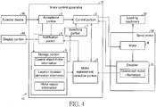
- FIG. 4 is a block diagram that illustrates a schematic structure of the motor control apparatus 1B and the control system 11 that includes the motor control apparatus 1B in the present implementation manner.
- the storage portion 3 of the motor control apparatus 1B of the present implementation manner stores the location deviation elimination information.
- location deviation elimination information refers to the following.
- the location deviation elimination information is "eliminated” in a case in which the motor does not generate location deviation and the motor control apparatus 1B performs general control on the motor M. Because origin undermined state occurs (location deviation is generated) due to replacement of the motor M, the location deviation elimination information is overwritten as "uneliminated”. Subsequently, when origin reset processing of the motor M is completed, the location deviation elimination information is overwritten as "eliminated”.
- indication of "location deviation elimination information” is not limited to “eliminated” and “uneliminated”. For example, “location deviation elimination information” may also be indicated by using "location offset” in the origin undetermined state. "Location deviation elimination information” is exemplarily indicated as “eliminated” and “uneliminated” for description below.
- the location deviation elimination information becomes "uneliminated”.
- the motor control apparatus 1B continues to perform limiting processing of the control portion 2, at least until the location deviation elimination information becomes "eliminated”. That is, the motor control apparatus 1B of the present implementation manner does not remove the limiting processing of the control portion 2 in a phase when an acceptance portion 5 accepts, from a user, an input of confirmation information of a confirmed intention of replacement of the motor.
- the motor control apparatus 1B executes the limiting processing, at least until origin reset processing is performed.
- the origin reset processing may be performed by enabling loading machinery 32 to move to an origin location, that is, by means of origin restoration.
- the origin restoration for example, may also be performed by manually moving the loading machinery 32 by the user. In this case, preferably, the user performs an input of an intention of the origin reset processing on an external device 50 after the origin restoration.
- the origin restoration may also be performed by entering an instruction of automatic restoration operation to the motor control apparatus 1B by the user.
- the origin reset processing may also be performed by entering an origin location offset, as a distance (location offset) between the loading machinery 32 and the origin location to the external device 50 by the user.
- the origin reset processing may also be performed by automatic origin restoration operation by the loading machinery 32 in a case in which motor replacement is detected.
- the user performs an input for accepting that the origin reset processing has been completed on the external device 50.
- the control portion 2 not only performs the input of the confirmation information of the confirmed intention of the replacement of the motor, but also continues to perform the limiting processing, until the origin reset processing of the motor is performed to eliminate location deviation of the motor. Therefore, the probability of performing action by the motor in state where location deviation occurs is reduced. A result thereof: the motor after the replacement can be prevented from performing unexpected action when action is started, resulting in that damages occur to the motor or the loading machinery 32.
- the sequence of entering the confirmation information and the origin reset processing of the motor is not limited, and either one may be performed first. Therefore, the content may be sorted, as stated below. That is, in a case in which a motor replacement detection portion 4 detects motor replacement, the control portion 2 of the motor control apparatus 1B executes the limiting processing, until the acceptance portion 5 accepts, from the user, the input of the confirmation information of the confirmed intention of the motor replacement and the origin reset processing of the motor is completed.
- the origin reset processing accompanies some user operations.
- the user must actively perform the input of the confirmation information and the origin reset processing. Therefore, the probability of performing action by the motor in state where location deviation occurs is extremely reduced.
- a motor control apparatus can be provided, which can enable the motor after the replacement to perform action in state of further ensuring security when the motor as a control object is replaced.
- a notification portion 6 first notifies abnormal information in a case in which motor replacement is detected. Then, when the user performs the input of the confirmation information, the notification portion 6 stops notifying the abnormal information. On the other aspect, in a case in which the origin location of the motor M is unclear, the notification portion 6 notifies alarm information that indicates an intention thereof. Subsequently, after the origin reset processing is performed, the notification portion 6 stops notifying the alarm information. In this way, the notification portion 6 performs two-phase notification.
- the user when the user performs the input of the confirmation information of the confirmed intention of the replacement of the motor, the user can further recognize that origin deviation of the motor must be eliminated. A result thereof: the user can be urged to practically perform elimination of the motor location deviation. In addition, the user can accurately master current conditions.
- notification of the abnormal information or alarm information may also be separately performed by means of a number displayed on a display portion 60, and a notification method of the notification portion 6 is not particularly limited.
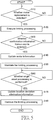
- Fig. 5 is flowchart that illustrates a flow of processing executed by the motor control apparatus 1B of the present implementation manner.
- description is made on general processing, in state of controlling the motor M and is relevant with motor replacement, performed by the motor control apparatus 1B.
- the motor control apparatus 1B first enables the motor replacement detection portion 4 to detect whether the motor has been replaced (S110).
- the motor control apparatus 1B continues to perform general control on a servo motor 30, and executes processing of S110 again.
- the motor control apparatus 1B enables the control portion 2 to execute limiting processing for limiting action of the motor after the replacement (S120).
- the motor control apparatus 1B sets the location deviation elimination information stored in the storage portion 3 as uneliminated.
- the notification portion 6 notifies abnormal information.
- a switching portion 7 switches the control portion 2 between execution and non-execution of limiting processing based on motor usage information. In a case in which the motor usage information is not an increment type, the control portion 2 executes limiting processing, and the flowchart proceeds to the next step.
- the motor control apparatus 1B enables the acceptance portion 5 to accept whether confirmation information from a user is entered (S130).
- the motor control apparatus 1B enables the control portion 2 to continue the limiting processing, and execute processing of S130 again.
- the acceptance portion 5 In a case in which the acceptance portion 5 receives the input of the confirmation information from the user (yes in S130), the acceptance portion 5 updates control object motor information of the storage portion 3 as connected motor information obtained from an encoder 31 after the replacement (S140).
- the control portion 2 maintains limiting processing (S150).
- the notification portion 6 ends notification of the abnormal information, and on the other aspect, notifies alarm information of an intention that location deviation occurs to the motor.
- the motor control apparatus 1B enables the acceptance portion 5 to accept whether information from the user is entered for origin reset processing (S160).
- the origin reset processing may the following processing. That is, the user may also enter origin reset completed to the external device 50 after the loading machinery 32 is moved to the origin location by means of automatic restoration operation or manually by the user. Or the user may also enter a difference (origin location offset) between a current location and the origin location of the loading machinery 32 to the external device 50.
- the motor control apparatus 1B enables the control portion 2 to continue the limiting processing, and execute processing of S160 again.
- the motor control apparatus 1B updates the location deviation elimination information of the storage portion 3 as "eliminated" (S170).
- the motor control apparatus 1B enables the control portion 2 to remove limiting processing (S180).
- the notification portion 6 stops notifying the alarm information.
- the motor control apparatus 1B performs general control on the motor M.
- the motor control method executed by the motor control apparatus 1B may be sorted, as stated below. That is, the motor control method executed by the motor control apparatus 1B is to perform control on the motor M, where the motor control method includes: a motor replacement detection step: detecting a condition of replacement of the motor M; an action limiting step: when the replacement of the motor M is detected in the motor replacement detection step, limiting action of the motor M after the replacement; and a location deviation elimination detection step: detecting conditions of completion of the origin reset processing on the motor M and location deviation elimination, where action limitation on the motor M lasts at least until location deviation detected in the location deviation elimination detection step is eliminated.
- a motor replacement detection step detecting a condition of replacement of the motor M
- an action limiting step when the replacement of the motor M is detected in the motor replacement detection step, limiting action of the motor M after the replacement
- a location deviation elimination detection step detecting conditions of completion of the origin reset processing on the motor M and location deviation elimination, where action limitation on the motor M lasts at least until location deviation detected in the
- the action limiting step lasts until location deviation detected in the location deviation elimination detection step is eliminated. Therefore, control on the motor M can be started after location deviation of the motor M is eliminated. Therefore, the motor control method achieves the following effect: when the replacement of the motor M as the control object is performed, the motor M after the replacement can be enabled to perform action in state of further ensuring security.
- the motor control apparatus 1A/1B of the implementation manner 1 and the implementation manner 2 includes a storage portion 3.
- a difference lies in that, a storage portion 3 is included in a servo motor 30 or an encoder 31.
- the servo motor 30 or encoder 31 includes the storage portion 3.
- the storage portion 3 stores at least control object motor information, preferably, further stores motor usage information and location deviation elimination information.
- a motor replacement detection portion 4 can obtain the information from the storage portion 3 of the servo motor 30 or the encoder 31, to detect replacement of the motor.
- the motor replacement detection portion 4 detects motor replacement. On such basis, the replacement of the motor can be detected more easily and practically.
- the storage portion 3 is included in the servo motor 30 or the encoder 31.
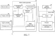
- a difference lies in that, a storage portion 3 is included in an upper controller 40.
- the control system 13 that includes the motor control apparatus 1D of the present implementation manner includes the upper controller 40 provided outside the motor control apparatus 1D.
- the upper controller 40 is connected to at least a motor replacement detection portion 4.
- the storage portion 3 is provided in the upper controller 40.
- the storage portion 3 stores at least control object motor information, preferably, further stores motor usage information and location deviation elimination information.
- the motor replacement detection portion 4 can obtain the information from the storage portion 3 of the upper controller 40, to detect replacement of a motor.
- the motor control apparatus 1D after the replacement can also obtain motor information from the upper controller 40 and an encoder 31, to perform control on a motor M. Therefore, even if a failure occurs to the motor control apparatus 1D, the motor control apparatus 1D can also be replaced to easily continue control on the motor M.
- Control blocks (block) of the motor control apparatus 1A to the motor control apparatus 1D not only may be implemented by means of a logic circuit (hardware (hardware)) formed on an integrated circuit (IC chip (chip)) and the like, but also may be implemented by using a CPU (Central Processing Unit) by means of software.
- a logic circuit hardware (hardware)
- IC chip integrated circuit
- CPU Central Processing Unit
- the motor control apparatus 1A to the motor control apparatus 1D have a CPU that executes a command for implementing software with various functions, that is, programs, a read only memory (Read Only Memory, ROM) or a storage apparatus (called “recording media”) that can be read by a computer (or CPU) and records the programs and various data, a random access memory (Random Access Memory, RAM) that expands the programs, and the like.
- the programs are read from the recording media and executed by using a computer (or CPU), so as to achieve the objective of the present invention.
- non-temporary tangible media may be used, for example, a tape (tape), a disk (disk), a card (card), a semiconductor memory, and a programmable logic circuit may be used.
- the programs may also be provided for the computer via any transmission medium (a communication network, a broadcast wave, or the like) that can transmit the programs.
- the present invention can also implement a form of data signals, instantiated and embedded in a carrier of the programs, by means of electronic transmission.
- the present invention is not limited to the implementation manners, and various modifications may be performed within a scope shown in the claims; an implementation manner obtained by suitably combining technical components respectively disclosed in different implementation manners also falls into the technical scope of the present invention.
Landscapes
- Engineering & Computer Science (AREA)
- Physics & Mathematics (AREA)
- General Physics & Mathematics (AREA)
- Automation & Control Theory (AREA)
- Power Engineering (AREA)
- Human Computer Interaction (AREA)
- Manufacturing & Machinery (AREA)
- Chemical & Material Sciences (AREA)
- Chemical Kinetics & Catalysis (AREA)
- Computer Security & Cryptography (AREA)
- Control Of Electric Motors In General (AREA)
Priority Applications (1)
| Application Number | Priority Date | Filing Date | Title |
|---|---|---|---|
| EP22161492.8A EP4057083B1 (fr) | 2016-03-10 | 2016-12-16 | Appareil de commande de moteur, procédé de commande de moteur, programme de traitement d'informations et support d'enregistrement |
Applications Claiming Priority (1)
| Application Number | Priority Date | Filing Date | Title |
|---|---|---|---|
| JP2016047565A JP6443366B2 (ja) | 2016-03-10 | 2016-03-10 | モータ制御装置、モータ制御方法、情報処理プログラム、および記録媒体 |
Related Child Applications (2)
| Application Number | Title | Priority Date | Filing Date |
|---|---|---|---|
| EP22161492.8A Division EP4057083B1 (fr) | 2016-03-10 | 2016-12-16 | Appareil de commande de moteur, procédé de commande de moteur, programme de traitement d'informations et support d'enregistrement |
| EP22161492.8A Division-Into EP4057083B1 (fr) | 2016-03-10 | 2016-12-16 | Appareil de commande de moteur, procédé de commande de moteur, programme de traitement d'informations et support d'enregistrement |
Publications (3)
| Publication Number | Publication Date |
|---|---|
| EP3217233A2 true EP3217233A2 (fr) | 2017-09-13 |
| EP3217233A3 EP3217233A3 (fr) | 2017-12-27 |
| EP3217233B1 EP3217233B1 (fr) | 2022-04-27 |
Family
ID=57821754
Family Applications (2)
| Application Number | Title | Priority Date | Filing Date |
|---|---|---|---|
| EP16204795.5A Active EP3217233B1 (fr) | 2016-03-10 | 2016-12-16 | Appareil de commande de moteur, procédé de commande de moteur, programme de traitement d'informations et support d'enregistrement |
| EP22161492.8A Active EP4057083B1 (fr) | 2016-03-10 | 2016-12-16 | Appareil de commande de moteur, procédé de commande de moteur, programme de traitement d'informations et support d'enregistrement |
Family Applications After (1)
| Application Number | Title | Priority Date | Filing Date |
|---|---|---|---|
| EP22161492.8A Active EP4057083B1 (fr) | 2016-03-10 | 2016-12-16 | Appareil de commande de moteur, procédé de commande de moteur, programme de traitement d'informations et support d'enregistrement |
Country Status (4)
| Country | Link |
|---|---|
| US (1) | US10416663B2 (fr) |
| EP (2) | EP3217233B1 (fr) |
| JP (1) | JP6443366B2 (fr) |
| CN (1) | CN107181442B (fr) |
Cited By (1)
| Publication number | Priority date | Publication date | Assignee | Title |
|---|---|---|---|---|
| EP3692380A4 (fr) * | 2017-12-18 | 2021-05-05 | Hewlett-Packard Development Company, L.P. | Identification de moteur avec moteurs multiples |
Families Citing this family (7)
| Publication number | Priority date | Publication date | Assignee | Title |
|---|---|---|---|---|
| JP7012222B2 (ja) * | 2016-09-14 | 2022-01-28 | パナソニックIpマネジメント株式会社 | モータ制御装置 |
| JP7087951B2 (ja) * | 2018-11-22 | 2022-06-21 | オムロン株式会社 | 制御システム、制御方法、ドライブ装置 |
| WO2022032587A1 (fr) * | 2020-08-13 | 2022-02-17 | Siemens Aktiengesellschaft | Codeur, moteur, entraînement par moteur et ordinateur hôte |
| JP7581982B2 (ja) * | 2021-03-09 | 2024-11-13 | オムロン株式会社 | モータ制御装置、及び、モータ制御装置における通信環境の調整方法 |
| JP7651889B2 (ja) * | 2021-03-10 | 2025-03-27 | オムロン株式会社 | サーボドライバ及びサーボシステム |
| JP2023134960A (ja) * | 2022-03-15 | 2023-09-28 | オムロン株式会社 | 制御システム |
| TWI885644B (zh) * | 2023-12-15 | 2025-06-01 | 國立中正大學 | 應用數位實境之工具機異警與輔助排除系統 |
Citations (1)
| Publication number | Priority date | Publication date | Assignee | Title |
|---|---|---|---|---|
| JP2003102195A (ja) | 2002-08-28 | 2003-04-04 | Yaskawa Electric Corp | モータ制御方法 |
Family Cites Families (27)
| Publication number | Priority date | Publication date | Assignee | Title |
|---|---|---|---|---|
| US5239247A (en) * | 1992-06-17 | 1993-08-24 | Cincinnati Milacron | Reconfigurable master-slave control |
| JPH09311055A (ja) * | 1996-05-22 | 1997-12-02 | Sanyo Denki Co Ltd | アブソリュートエンコーダ |
| DE19882317C2 (de) | 1998-02-27 | 2003-12-04 | Mitsubishi Electric Corp | Steuereinrichtung für eine Nähmaschine |
| DE10037968B4 (de) * | 2000-08-03 | 2007-02-08 | Siemens Ag | Elektrischer Antrieb mit Motoridentifizierung und Verfahren zur Motoridentifizierung |
| JP2002335699A (ja) * | 2001-05-09 | 2002-11-22 | Hitachi Ltd | 交流モータの制御装置 |
| JP2003153570A (ja) * | 2001-11-09 | 2003-05-23 | Hanshin Electric Co Ltd | ファンモータ制御装置 |
| US6829565B2 (en) * | 2003-02-14 | 2004-12-07 | Xerox Corporation | Stepper motor automated self-test routine |
| US7135830B2 (en) * | 2003-09-30 | 2006-11-14 | Reliance Electric Technologies, Llc | System and method for identifying operational parameters of a motor |
| US7184902B2 (en) * | 2003-09-30 | 2007-02-27 | Reliance Electric Technologies, Llc | Motor parameter estimation method and apparatus |
| WO2005034604A2 (fr) * | 2003-10-03 | 2005-04-21 | Black & Decker, Inc. | Procedes pour controler la decharge d'un bloc-pile d'un systeme d'outil electrique sans fil, systeme d'outil electrique sans fil et bloc-pile conçus avec une protection contre la decharge excessive et un controle de decharge |
| US7847505B2 (en) * | 2004-02-25 | 2010-12-07 | Siemens Industry, Inc. | System and method for configuring a soft starter |
| US7707461B2 (en) * | 2007-01-31 | 2010-04-27 | Hewlett-Packard Development Company, L.P. | Digital media drive failure prediction system and method |
| DE102007026678A1 (de) * | 2007-06-08 | 2008-12-11 | Abb Ag | Verfahren zum Austausch eines defekten Feldgerätes gegen ein neues Feldgerät in einem über digitalen Feldbus kommunizierenden System, insbesondere Automatisierungssystem |
| JP2009195087A (ja) * | 2008-02-18 | 2009-08-27 | Nsk Ltd | 回転角度位置検出装置 |
| DE102009007559B4 (de) * | 2009-02-04 | 2017-07-06 | Sew-Eurodrive Gmbh & Co Kg | Antriebssystem, Mehrfachantriebssystem, Verfahren zum Überprüfen eines Antriebssystems oder Mehrfachantriebssystems, Verfahren zur Inbetriebnahme einer Maschine, Maschine mit einem Antriebssystem oder Mehrfachantriebssystem, Computerprogramm und –produkt |
| JP5447260B2 (ja) * | 2010-02-11 | 2014-03-19 | 株式会社デンソー | 電池電圧監視装置 |
| JP5609817B2 (ja) * | 2011-08-11 | 2014-10-22 | オムロン株式会社 | 無線センサモジュール、それによる測定データの処理方法、プログラムおよび記録媒体 |
| JP5716924B2 (ja) * | 2012-04-23 | 2015-05-13 | トヨタ自動車株式会社 | 車両の制御装置 |
| SG2012072195A (en) * | 2012-09-27 | 2014-04-28 | Rockwell Automation Asia Pacific Business Ctr Pte Ltd | Modular motor drive system and method |
| SG2012072203A (en) * | 2012-09-27 | 2014-04-28 | Rockwell Automation Asia Pacific Business Ctr Pte Ltd | Motor drive configuration system and method |
| US8917045B2 (en) * | 2012-11-19 | 2014-12-23 | Nidec Motor Corporation | Methods and systems for selecting and programming replacement motors |
| KR20150060985A (ko) * | 2013-01-11 | 2015-06-03 | 미쓰비시덴키 가부시키가이샤 | 인코더, 서보 앰프, 컨트롤러, 및 서보 시스템에 있어서의 정보 교환 방법 |
| US10402881B2 (en) * | 2014-02-25 | 2019-09-03 | Regal Beloit America, Inc. | Methods and systems for identifying a replacement motor |
| US9491242B2 (en) * | 2014-04-11 | 2016-11-08 | Nidec Motor Corporation | Systems and methods for selecting and wirelessly programming a motor |
| US10832495B2 (en) * | 2014-04-18 | 2020-11-10 | Carefusion 303, Inc. | Remote maintenance of medical devices |
| JP6174649B2 (ja) * | 2015-09-30 | 2017-08-02 | ファナック株式会社 | ファンモータの予防保全機能を備えたモータ駆動装置 |
| US10448564B2 (en) * | 2016-03-30 | 2019-10-22 | Steering Solutions Ip Holding Corporation | Motor exchange system for a machine |
-
2016
- 2016-03-10 JP JP2016047565A patent/JP6443366B2/ja active Active
- 2016-12-16 EP EP16204795.5A patent/EP3217233B1/fr active Active
- 2016-12-16 EP EP22161492.8A patent/EP4057083B1/fr active Active
- 2016-12-18 US US15/382,730 patent/US10416663B2/en active Active
- 2016-12-20 CN CN201611190305.9A patent/CN107181442B/zh active Active
Patent Citations (1)
| Publication number | Priority date | Publication date | Assignee | Title |
|---|---|---|---|---|
| JP2003102195A (ja) | 2002-08-28 | 2003-04-04 | Yaskawa Electric Corp | モータ制御方法 |
Cited By (1)
| Publication number | Priority date | Publication date | Assignee | Title |
|---|---|---|---|---|
| EP3692380A4 (fr) * | 2017-12-18 | 2021-05-05 | Hewlett-Packard Development Company, L.P. | Identification de moteur avec moteurs multiples |
Also Published As
| Publication number | Publication date |
|---|---|
| EP4057083B1 (fr) | 2025-03-26 |
| EP4057083A1 (fr) | 2022-09-14 |
| CN107181442B (zh) | 2020-06-02 |
| CN107181442A (zh) | 2017-09-19 |
| EP3217233A3 (fr) | 2017-12-27 |
| JP6443366B2 (ja) | 2018-12-26 |
| EP3217233B1 (fr) | 2022-04-27 |
| US20170261973A1 (en) | 2017-09-14 |
| US10416663B2 (en) | 2019-09-17 |
| JP2017163760A (ja) | 2017-09-14 |
Similar Documents
| Publication | Publication Date | Title |
|---|---|---|
| EP3217233B1 (fr) | Appareil de commande de moteur, procédé de commande de moteur, programme de traitement d'informations et support d'enregistrement | |
| KR101823847B1 (ko) | 모터 제어 장치의 커스터마이즈 방법, 및 모터 제어 장치 | |
| EP3809580B1 (fr) | Véhicule électrique, procédé et dispositif de diagnostic de position initiale de transformateur rotatif, et support lisible par ordinateur | |
| EP1826644A2 (fr) | Commande numérique | |
| US10122314B2 (en) | Motor control apparatus, motor control system, motor control method | |
| US11701766B2 (en) | Tool, and control circuit and control method therefor | |
| CN102969975A (zh) | 电动机系统及电动机控制装置 | |
| US6119610A (en) | Sewing machine controller | |
| EP3101537A1 (fr) | Dispositif de commande, système de commande, procédé de commande pour dispositif de commande et procédé de commande pour système de commande | |
| CN113632017B (zh) | 驱动控制装置 | |
| CN110297463B (zh) | 输入错误检测装置 | |
| US20060229760A1 (en) | Numerical control system | |
| US11650571B2 (en) | Control device, control method, and control program for executing a machining program using flag indications | |
| US10139919B2 (en) | Electronic device and numerical controller | |
| CN113635136B (zh) | 刀库准停控制方法、装置、设备及存储介质 | |
| EP3082251B1 (fr) | Dispositif de commande de moteur électrique | |
| CN106569861B (zh) | 芯片iap数据更新控制方法及系统 | |
| CN110161971B (zh) | 参数决定辅助装置和记录有程序的计算机可读介质 | |
| CN111045394B (zh) | 数值控制装置 | |
| CN110908339B (zh) | 数值控制装置 | |
| US11205983B2 (en) | Motor control device and motor control method | |
| CN110275485B (zh) | 数值控制装置 | |
| JP2002171790A (ja) | 電動アクチュエータの制御装置 |
Legal Events
| Date | Code | Title | Description |
|---|---|---|---|
| PUAI | Public reference made under article 153(3) epc to a published international application that has entered the european phase |
Free format text: ORIGINAL CODE: 0009012 |
|
| STAA | Information on the status of an ep patent application or granted ep patent |
Free format text: STATUS: REQUEST FOR EXAMINATION WAS MADE |
|
| 17P | Request for examination filed |
Effective date: 20161216 |
|
| AK | Designated contracting states |
Kind code of ref document: A2 Designated state(s): AL AT BE BG CH CY CZ DE DK EE ES FI FR GB GR HR HU IE IS IT LI LT LU LV MC MK MT NL NO PL PT RO RS SE SI SK SM TR |
|
| AX | Request for extension of the european patent |
Extension state: BA ME |
|
| PUAL | Search report despatched |
Free format text: ORIGINAL CODE: 0009013 |
|
| AK | Designated contracting states |
Kind code of ref document: A3 Designated state(s): AL AT BE BG CH CY CZ DE DK EE ES FI FR GB GR HR HU IE IS IT LI LT LU LV MC MK MT NL NO PL PT RO RS SE SI SK SM TR |
|
| AX | Request for extension of the european patent |
Extension state: BA ME |
|
| RIC1 | Information provided on ipc code assigned before grant |
Ipc: G05B 19/042 20060101ALI20171121BHEP Ipc: G05B 19/406 20060101ALI20171121BHEP Ipc: G05B 9/02 20060101AFI20171121BHEP Ipc: G05B 23/02 20060101ALI20171121BHEP |
|
| RBV | Designated contracting states (corrected) |
Designated state(s): AL AT BE BG CH CY CZ DE DK EE ES FI FR GB GR HR HU IE IS IT LI LT LU LV MC MK MT NL NO PL PT RO RS SE SI SK SM TR |
|
| STAA | Information on the status of an ep patent application or granted ep patent |
Free format text: STATUS: EXAMINATION IS IN PROGRESS |
|
| 17Q | First examination report despatched |
Effective date: 20201103 |
|
| GRAP | Despatch of communication of intention to grant a patent |
Free format text: ORIGINAL CODE: EPIDOSNIGR1 |
|
| STAA | Information on the status of an ep patent application or granted ep patent |
Free format text: STATUS: GRANT OF PATENT IS INTENDED |
|
| INTG | Intention to grant announced |
Effective date: 20211117 |
|
| GRAS | Grant fee paid |
Free format text: ORIGINAL CODE: EPIDOSNIGR3 |
|
| GRAA | (expected) grant |
Free format text: ORIGINAL CODE: 0009210 |
|
| STAA | Information on the status of an ep patent application or granted ep patent |
Free format text: STATUS: THE PATENT HAS BEEN GRANTED |
|
| AK | Designated contracting states |
Kind code of ref document: B1 Designated state(s): AL AT BE BG CH CY CZ DE DK EE ES FI FR GB GR HR HU IE IS IT LI LT LU LV MC MK MT NL NO PL PT RO RS SE SI SK SM TR |
|
| REG | Reference to a national code |
Ref country code: GB Ref legal event code: FG4D |
|
| REG | Reference to a national code |
Ref country code: CH Ref legal event code: EP |
|
| REG | Reference to a national code |
Ref country code: DE Ref legal event code: R096 Ref document number: 602016071458 Country of ref document: DE |
|
| REG | Reference to a national code |
Ref country code: AT Ref legal event code: REF Ref document number: 1487413 Country of ref document: AT Kind code of ref document: T Effective date: 20220515 |
|
| REG | Reference to a national code |
Ref country code: IE Ref legal event code: FG4D |
|
| REG | Reference to a national code |
Ref country code: LT Ref legal event code: MG9D |
|
| REG | Reference to a national code |
Ref country code: NL Ref legal event code: MP Effective date: 20220427 |
|
| REG | Reference to a national code |
Ref country code: AT Ref legal event code: MK05 Ref document number: 1487413 Country of ref document: AT Kind code of ref document: T Effective date: 20220427 |
|
| PG25 | Lapsed in a contracting state [announced via postgrant information from national office to epo] |
Ref country code: NL Free format text: LAPSE BECAUSE OF FAILURE TO SUBMIT A TRANSLATION OF THE DESCRIPTION OR TO PAY THE FEE WITHIN THE PRESCRIBED TIME-LIMIT Effective date: 20220427 |
|
| PG25 | Lapsed in a contracting state [announced via postgrant information from national office to epo] |
Ref country code: SE Free format text: LAPSE BECAUSE OF FAILURE TO SUBMIT A TRANSLATION OF THE DESCRIPTION OR TO PAY THE FEE WITHIN THE PRESCRIBED TIME-LIMIT Effective date: 20220427 Ref country code: PT Free format text: LAPSE BECAUSE OF FAILURE TO SUBMIT A TRANSLATION OF THE DESCRIPTION OR TO PAY THE FEE WITHIN THE PRESCRIBED TIME-LIMIT Effective date: 20220829 Ref country code: NO Free format text: LAPSE BECAUSE OF FAILURE TO SUBMIT A TRANSLATION OF THE DESCRIPTION OR TO PAY THE FEE WITHIN THE PRESCRIBED TIME-LIMIT Effective date: 20220727 Ref country code: LT Free format text: LAPSE BECAUSE OF FAILURE TO SUBMIT A TRANSLATION OF THE DESCRIPTION OR TO PAY THE FEE WITHIN THE PRESCRIBED TIME-LIMIT Effective date: 20220427 Ref country code: HR Free format text: LAPSE BECAUSE OF FAILURE TO SUBMIT A TRANSLATION OF THE DESCRIPTION OR TO PAY THE FEE WITHIN THE PRESCRIBED TIME-LIMIT Effective date: 20220427 Ref country code: GR Free format text: LAPSE BECAUSE OF FAILURE TO SUBMIT A TRANSLATION OF THE DESCRIPTION OR TO PAY THE FEE WITHIN THE PRESCRIBED TIME-LIMIT Effective date: 20220728 Ref country code: FI Free format text: LAPSE BECAUSE OF FAILURE TO SUBMIT A TRANSLATION OF THE DESCRIPTION OR TO PAY THE FEE WITHIN THE PRESCRIBED TIME-LIMIT Effective date: 20220427 Ref country code: ES Free format text: LAPSE BECAUSE OF FAILURE TO SUBMIT A TRANSLATION OF THE DESCRIPTION OR TO PAY THE FEE WITHIN THE PRESCRIBED TIME-LIMIT Effective date: 20220427 Ref country code: BG Free format text: LAPSE BECAUSE OF FAILURE TO SUBMIT A TRANSLATION OF THE DESCRIPTION OR TO PAY THE FEE WITHIN THE PRESCRIBED TIME-LIMIT Effective date: 20220727 Ref country code: AT Free format text: LAPSE BECAUSE OF FAILURE TO SUBMIT A TRANSLATION OF THE DESCRIPTION OR TO PAY THE FEE WITHIN THE PRESCRIBED TIME-LIMIT Effective date: 20220427 |
|
| PG25 | Lapsed in a contracting state [announced via postgrant information from national office to epo] |
Ref country code: RS Free format text: LAPSE BECAUSE OF FAILURE TO SUBMIT A TRANSLATION OF THE DESCRIPTION OR TO PAY THE FEE WITHIN THE PRESCRIBED TIME-LIMIT Effective date: 20220427 Ref country code: PL Free format text: LAPSE BECAUSE OF FAILURE TO SUBMIT A TRANSLATION OF THE DESCRIPTION OR TO PAY THE FEE WITHIN THE PRESCRIBED TIME-LIMIT Effective date: 20220427 Ref country code: LV Free format text: LAPSE BECAUSE OF FAILURE TO SUBMIT A TRANSLATION OF THE DESCRIPTION OR TO PAY THE FEE WITHIN THE PRESCRIBED TIME-LIMIT Effective date: 20220427 Ref country code: IS Free format text: LAPSE BECAUSE OF FAILURE TO SUBMIT A TRANSLATION OF THE DESCRIPTION OR TO PAY THE FEE WITHIN THE PRESCRIBED TIME-LIMIT Effective date: 20220827 |
|
| REG | Reference to a national code |
Ref country code: DE Ref legal event code: R097 Ref document number: 602016071458 Country of ref document: DE |
|
| PG25 | Lapsed in a contracting state [announced via postgrant information from national office to epo] |
Ref country code: SM Free format text: LAPSE BECAUSE OF FAILURE TO SUBMIT A TRANSLATION OF THE DESCRIPTION OR TO PAY THE FEE WITHIN THE PRESCRIBED TIME-LIMIT Effective date: 20220427 Ref country code: SK Free format text: LAPSE BECAUSE OF FAILURE TO SUBMIT A TRANSLATION OF THE DESCRIPTION OR TO PAY THE FEE WITHIN THE PRESCRIBED TIME-LIMIT Effective date: 20220427 Ref country code: RO Free format text: LAPSE BECAUSE OF FAILURE TO SUBMIT A TRANSLATION OF THE DESCRIPTION OR TO PAY THE FEE WITHIN THE PRESCRIBED TIME-LIMIT Effective date: 20220427 Ref country code: EE Free format text: LAPSE BECAUSE OF FAILURE TO SUBMIT A TRANSLATION OF THE DESCRIPTION OR TO PAY THE FEE WITHIN THE PRESCRIBED TIME-LIMIT Effective date: 20220427 Ref country code: DK Free format text: LAPSE BECAUSE OF FAILURE TO SUBMIT A TRANSLATION OF THE DESCRIPTION OR TO PAY THE FEE WITHIN THE PRESCRIBED TIME-LIMIT Effective date: 20220427 Ref country code: CZ Free format text: LAPSE BECAUSE OF FAILURE TO SUBMIT A TRANSLATION OF THE DESCRIPTION OR TO PAY THE FEE WITHIN THE PRESCRIBED TIME-LIMIT Effective date: 20220427 |
|
| PLBE | No opposition filed within time limit |
Free format text: ORIGINAL CODE: 0009261 |
|
| STAA | Information on the status of an ep patent application or granted ep patent |
Free format text: STATUS: NO OPPOSITION FILED WITHIN TIME LIMIT |
|
| PG25 | Lapsed in a contracting state [announced via postgrant information from national office to epo] |
Ref country code: AL Free format text: LAPSE BECAUSE OF FAILURE TO SUBMIT A TRANSLATION OF THE DESCRIPTION OR TO PAY THE FEE WITHIN THE PRESCRIBED TIME-LIMIT Effective date: 20220427 |
|
| 26N | No opposition filed |
Effective date: 20230130 |
|
| PG25 | Lapsed in a contracting state [announced via postgrant information from national office to epo] |
Ref country code: SI Free format text: LAPSE BECAUSE OF FAILURE TO SUBMIT A TRANSLATION OF THE DESCRIPTION OR TO PAY THE FEE WITHIN THE PRESCRIBED TIME-LIMIT Effective date: 20220427 |
|
| REG | Reference to a national code |
Ref country code: CH Ref legal event code: PL |
|
| GBPC | Gb: european patent ceased through non-payment of renewal fee |
Effective date: 20221216 |
|
| REG | Reference to a national code |
Ref country code: BE Ref legal event code: MM Effective date: 20221231 |
|
| PG25 | Lapsed in a contracting state [announced via postgrant information from national office to epo] |
Ref country code: LU Free format text: LAPSE BECAUSE OF NON-PAYMENT OF DUE FEES Effective date: 20221216 |
|
| PG25 | Lapsed in a contracting state [announced via postgrant information from national office to epo] |
Ref country code: LI Free format text: LAPSE BECAUSE OF NON-PAYMENT OF DUE FEES Effective date: 20221231 Ref country code: IE Free format text: LAPSE BECAUSE OF NON-PAYMENT OF DUE FEES Effective date: 20221216 Ref country code: GB Free format text: LAPSE BECAUSE OF NON-PAYMENT OF DUE FEES Effective date: 20221216 Ref country code: CH Free format text: LAPSE BECAUSE OF NON-PAYMENT OF DUE FEES Effective date: 20221231 |
|
| PG25 | Lapsed in a contracting state [announced via postgrant information from national office to epo] |
Ref country code: FR Free format text: LAPSE BECAUSE OF NON-PAYMENT OF DUE FEES Effective date: 20221231 Ref country code: BE Free format text: LAPSE BECAUSE OF NON-PAYMENT OF DUE FEES Effective date: 20221231 |
|
| PG25 | Lapsed in a contracting state [announced via postgrant information from national office to epo] |
Ref country code: IT Free format text: LAPSE BECAUSE OF FAILURE TO SUBMIT A TRANSLATION OF THE DESCRIPTION OR TO PAY THE FEE WITHIN THE PRESCRIBED TIME-LIMIT Effective date: 20220427 |
|
| PG25 | Lapsed in a contracting state [announced via postgrant information from national office to epo] |
Ref country code: HU Free format text: LAPSE BECAUSE OF FAILURE TO SUBMIT A TRANSLATION OF THE DESCRIPTION OR TO PAY THE FEE WITHIN THE PRESCRIBED TIME-LIMIT; INVALID AB INITIO Effective date: 20161216 |
|
| PG25 | Lapsed in a contracting state [announced via postgrant information from national office to epo] |
Ref country code: CY Free format text: LAPSE BECAUSE OF FAILURE TO SUBMIT A TRANSLATION OF THE DESCRIPTION OR TO PAY THE FEE WITHIN THE PRESCRIBED TIME-LIMIT Effective date: 20220427 |
|
| PG25 | Lapsed in a contracting state [announced via postgrant information from national office to epo] |
Ref country code: MK Free format text: LAPSE BECAUSE OF FAILURE TO SUBMIT A TRANSLATION OF THE DESCRIPTION OR TO PAY THE FEE WITHIN THE PRESCRIBED TIME-LIMIT Effective date: 20220427 |
|
| PG25 | Lapsed in a contracting state [announced via postgrant information from national office to epo] |
Ref country code: MC Free format text: LAPSE BECAUSE OF FAILURE TO SUBMIT A TRANSLATION OF THE DESCRIPTION OR TO PAY THE FEE WITHIN THE PRESCRIBED TIME-LIMIT Effective date: 20220427 |
|
| PG25 | Lapsed in a contracting state [announced via postgrant information from national office to epo] |
Ref country code: MC Free format text: LAPSE BECAUSE OF FAILURE TO SUBMIT A TRANSLATION OF THE DESCRIPTION OR TO PAY THE FEE WITHIN THE PRESCRIBED TIME-LIMIT Effective date: 20220427 |
|
| PG25 | Lapsed in a contracting state [announced via postgrant information from national office to epo] |
Ref country code: MT Free format text: LAPSE BECAUSE OF FAILURE TO SUBMIT A TRANSLATION OF THE DESCRIPTION OR TO PAY THE FEE WITHIN THE PRESCRIBED TIME-LIMIT Effective date: 20220427 |
|
| PG25 | Lapsed in a contracting state [announced via postgrant information from national office to epo] |
Ref country code: BG Free format text: LAPSE BECAUSE OF FAILURE TO SUBMIT A TRANSLATION OF THE DESCRIPTION OR TO PAY THE FEE WITHIN THE PRESCRIBED TIME-LIMIT Effective date: 20220427 |
|
| PG25 | Lapsed in a contracting state [announced via postgrant information from national office to epo] |
Ref country code: BG Free format text: LAPSE BECAUSE OF FAILURE TO SUBMIT A TRANSLATION OF THE DESCRIPTION OR TO PAY THE FEE WITHIN THE PRESCRIBED TIME-LIMIT Effective date: 20220427 |
|
| PG25 | Lapsed in a contracting state [announced via postgrant information from national office to epo] |
Ref country code: TR Free format text: LAPSE BECAUSE OF FAILURE TO SUBMIT A TRANSLATION OF THE DESCRIPTION OR TO PAY THE FEE WITHIN THE PRESCRIBED TIME-LIMIT Effective date: 20220427 |
|
| PGFP | Annual fee paid to national office [announced via postgrant information from national office to epo] |
Ref country code: DE Payment date: 20251222 Year of fee payment: 10 |