EP3217909B1 - Bras de support intelligent pour chirurgie de la tête avec commandes sensibles au contact - Google Patents
Bras de support intelligent pour chirurgie de la tête avec commandes sensibles au contact Download PDFInfo
- Publication number
- EP3217909B1 EP3217909B1 EP15795146.8A EP15795146A EP3217909B1 EP 3217909 B1 EP3217909 B1 EP 3217909B1 EP 15795146 A EP15795146 A EP 15795146A EP 3217909 B1 EP3217909 B1 EP 3217909B1
- Authority
- EP
- European Patent Office
- Prior art keywords
- arm
- holding arm
- interface
- contact
- joint
- Prior art date
- Legal status (The legal status is an assumption and is not a legal conclusion. Google has not performed a legal analysis and makes no representation as to the accuracy of the status listed.)
- Active
Links
Images




Classifications
-
- A—HUMAN NECESSITIES
- A61—MEDICAL OR VETERINARY SCIENCE; HYGIENE
- A61B—DIAGNOSIS; SURGERY; IDENTIFICATION
- A61B90/00—Instruments, implements or accessories specially adapted for surgery or diagnosis and not covered by any of the groups A61B1/00 - A61B50/00, e.g. for luxation treatment or for protecting wound edges
- A61B90/50—Supports for surgical instruments, e.g. articulated arms
-
- A—HUMAN NECESSITIES
- A61—MEDICAL OR VETERINARY SCIENCE; HYGIENE
- A61B—DIAGNOSIS; SURGERY; IDENTIFICATION
- A61B1/00—Instruments for performing medical examinations of the interior of cavities or tubes of the body by visual or photographical inspection, e.g. endoscopes; Illuminating arrangements therefor
- A61B1/00147—Holding or positioning arrangements
- A61B1/00149—Holding or positioning arrangements using articulated arms
-
- A—HUMAN NECESSITIES
- A61—MEDICAL OR VETERINARY SCIENCE; HYGIENE
- A61B—DIAGNOSIS; SURGERY; IDENTIFICATION
- A61B17/00—Surgical instruments, devices or methods
-
- A—HUMAN NECESSITIES
- A61—MEDICAL OR VETERINARY SCIENCE; HYGIENE
- A61B—DIAGNOSIS; SURGERY; IDENTIFICATION
- A61B34/00—Computer-aided surgery; Manipulators or robots specially adapted for use in surgery
- A61B34/25—User interfaces for surgical systems
-
- A—HUMAN NECESSITIES
- A61—MEDICAL OR VETERINARY SCIENCE; HYGIENE
- A61B—DIAGNOSIS; SURGERY; IDENTIFICATION
- A61B34/00—Computer-aided surgery; Manipulators or robots specially adapted for use in surgery
- A61B34/30—Surgical robots
-
- A—HUMAN NECESSITIES
- A61—MEDICAL OR VETERINARY SCIENCE; HYGIENE
- A61B—DIAGNOSIS; SURGERY; IDENTIFICATION
- A61B34/00—Computer-aided surgery; Manipulators or robots specially adapted for use in surgery
- A61B34/70—Manipulators specially adapted for use in surgery
-
- A—HUMAN NECESSITIES
- A61—MEDICAL OR VETERINARY SCIENCE; HYGIENE
- A61B—DIAGNOSIS; SURGERY; IDENTIFICATION
- A61B34/00—Computer-aided surgery; Manipulators or robots specially adapted for use in surgery
- A61B34/70—Manipulators specially adapted for use in surgery
- A61B34/74—Manipulators with manual electric input means
-
- A—HUMAN NECESSITIES
- A61—MEDICAL OR VETERINARY SCIENCE; HYGIENE
- A61B—DIAGNOSIS; SURGERY; IDENTIFICATION
- A61B90/00—Instruments, implements or accessories specially adapted for surgery or diagnosis and not covered by any of the groups A61B1/00 - A61B50/00, e.g. for luxation treatment or for protecting wound edges
- A61B90/36—Image-producing devices or illumination devices not otherwise provided for
- A61B90/37—Surgical systems with images on a monitor during operation
-
- B—PERFORMING OPERATIONS; TRANSPORTING
- B25—HAND TOOLS; PORTABLE POWER-DRIVEN TOOLS; MANIPULATORS
- B25J—MANIPULATORS; CHAMBERS PROVIDED WITH MANIPULATION DEVICES
- B25J13/00—Controls for manipulators
- B25J13/08—Controls for manipulators by means of sensing devices, e.g. viewing or touching devices
- B25J13/081—Touching devices, e.g. pressure-sensitive
- B25J13/084—Tactile sensors
-
- B—PERFORMING OPERATIONS; TRANSPORTING
- B25—HAND TOOLS; PORTABLE POWER-DRIVEN TOOLS; MANIPULATORS
- B25J—MANIPULATORS; CHAMBERS PROVIDED WITH MANIPULATION DEVICES
- B25J19/00—Accessories fitted to manipulators, e.g. for monitoring, for viewing; Safety devices combined with or specially adapted for use in connection with manipulators
- B25J19/0004—Braking devices
-
- B—PERFORMING OPERATIONS; TRANSPORTING
- B25—HAND TOOLS; PORTABLE POWER-DRIVEN TOOLS; MANIPULATORS
- B25J—MANIPULATORS; CHAMBERS PROVIDED WITH MANIPULATION DEVICES
- B25J19/00—Accessories fitted to manipulators, e.g. for monitoring, for viewing; Safety devices combined with or specially adapted for use in connection with manipulators
- B25J19/0008—Balancing devices
-
- B—PERFORMING OPERATIONS; TRANSPORTING
- B25—HAND TOOLS; PORTABLE POWER-DRIVEN TOOLS; MANIPULATORS
- B25J—MANIPULATORS; CHAMBERS PROVIDED WITH MANIPULATION DEVICES
- B25J19/00—Accessories fitted to manipulators, e.g. for monitoring, for viewing; Safety devices combined with or specially adapted for use in connection with manipulators
- B25J19/02—Sensing devices
- B25J19/021—Optical sensing devices
- B25J19/023—Optical sensing devices including video camera means
-
- A—HUMAN NECESSITIES
- A61—MEDICAL OR VETERINARY SCIENCE; HYGIENE
- A61B—DIAGNOSIS; SURGERY; IDENTIFICATION
- A61B17/00—Surgical instruments, devices or methods
- A61B2017/00017—Electrical control of surgical instruments
- A61B2017/00203—Electrical control of surgical instruments with speech control or speech recognition
-
- A—HUMAN NECESSITIES
- A61—MEDICAL OR VETERINARY SCIENCE; HYGIENE
- A61B—DIAGNOSIS; SURGERY; IDENTIFICATION
- A61B17/00—Surgical instruments, devices or methods
- A61B2017/00477—Coupling
-
- A—HUMAN NECESSITIES
- A61—MEDICAL OR VETERINARY SCIENCE; HYGIENE
- A61B—DIAGNOSIS; SURGERY; IDENTIFICATION
- A61B34/00—Computer-aided surgery; Manipulators or robots specially adapted for use in surgery
- A61B34/20—Surgical navigation systems; Devices for tracking or guiding surgical instruments, e.g. for frameless stereotaxis
- A61B2034/2046—Tracking techniques
- A61B2034/2048—Tracking techniques using an accelerometer or inertia sensor
-
- A—HUMAN NECESSITIES
- A61—MEDICAL OR VETERINARY SCIENCE; HYGIENE
- A61B—DIAGNOSIS; SURGERY; IDENTIFICATION
- A61B34/00—Computer-aided surgery; Manipulators or robots specially adapted for use in surgery
- A61B34/20—Surgical navigation systems; Devices for tracking or guiding surgical instruments, e.g. for frameless stereotaxis
- A61B2034/2046—Tracking techniques
- A61B2034/2059—Mechanical position encoders
-
- A—HUMAN NECESSITIES
- A61—MEDICAL OR VETERINARY SCIENCE; HYGIENE
- A61B—DIAGNOSIS; SURGERY; IDENTIFICATION
- A61B90/00—Instruments, implements or accessories specially adapted for surgery or diagnosis and not covered by any of the groups A61B1/00 - A61B50/00, e.g. for luxation treatment or for protecting wound edges
- A61B90/06—Measuring instruments not otherwise provided for
- A61B2090/064—Measuring instruments not otherwise provided for for measuring force, pressure or mechanical tension
- A61B2090/066—Measuring instruments not otherwise provided for for measuring force, pressure or mechanical tension for measuring torque
-
- A—HUMAN NECESSITIES
- A61—MEDICAL OR VETERINARY SCIENCE; HYGIENE
- A61B—DIAGNOSIS; SURGERY; IDENTIFICATION
- A61B90/00—Instruments, implements or accessories specially adapted for surgery or diagnosis and not covered by any of the groups A61B1/00 - A61B50/00, e.g. for luxation treatment or for protecting wound edges
- A61B90/50—Supports for surgical instruments, e.g. articulated arms
- A61B2090/508—Supports for surgical instruments, e.g. articulated arms with releasable brake mechanisms
-
- A—HUMAN NECESSITIES
- A61—MEDICAL OR VETERINARY SCIENCE; HYGIENE
- A61B—DIAGNOSIS; SURGERY; IDENTIFICATION
- A61B90/00—Instruments, implements or accessories specially adapted for surgery or diagnosis and not covered by any of the groups A61B1/00 - A61B50/00, e.g. for luxation treatment or for protecting wound edges
- A61B90/50—Supports for surgical instruments, e.g. articulated arms
- A61B90/57—Accessory clamps
- A61B2090/571—Accessory clamps for clamping a support arm to a bed or other supports
-
- A—HUMAN NECESSITIES
- A61—MEDICAL OR VETERINARY SCIENCE; HYGIENE
- A61B—DIAGNOSIS; SURGERY; IDENTIFICATION
- A61B90/00—Instruments, implements or accessories specially adapted for surgery or diagnosis and not covered by any of the groups A61B1/00 - A61B50/00, e.g. for luxation treatment or for protecting wound edges
- A61B90/10—Instruments, implements or accessories specially adapted for surgery or diagnosis and not covered by any of the groups A61B1/00 - A61B50/00, e.g. for luxation treatment or for protecting wound edges for stereotaxic surgery, e.g. frame-based stereotaxis
Definitions
- the disclosure relates to a holding arm for medical purposes, in particular for holding a surgical mechatronic assistance system and/or surgical instrument, having a proximal end for fastening the holding arm to a base and a distal end for receiving a surgical mechatronic assistance system and/or surgical instrument; at least a first and a second arm segment, wherein the first arm segment is connected to a first joint and the second arm segment is connected to a second joint, wherein each joint is releasable and lockable.
- the disclosure further relates to a method for positioning a surgical mechatronic assistance system and/or surgical instrument coupled to a holding arm.
- the disclosure further relates to a holding arm for medical purposes, in particular for holding a surgical mechatronic assistance system, having a proximal end for attaching the holding arm to a base and a distal end for receiving a surgical mechatronic assistance system, and two or more arm segments and two or more joints by means of which the arm segments are connected to one another in an articulated manner, wherein each joint can be released and locked by means of an operating device.
- the disclosure further relates to a method for controlling a mechatronic assistance system coupled to a holding arm, in particular using such a holding arm.
- Holding arms of the type mentioned above have been known for some time and are used in surgery in particular to relieve a surgeon of static holding work.
- a holding arm is used to hold a mechatronic assistance system and/or a surgical instrument, such as a manipulator, an endoscope, a surgical clamp and the like.
- the holding arms mentioned above have proven particularly effective for holding endoscopes.
- endoscopic surgery a surgeon usually operates an instrument with both hands, while an assistant holds the endoscope to make the surgical field visible on a screen. Holding the endoscope for an extended period of time is very tiring. For this reason, holding arms are being used more and more.
- Such a holding arm is made, for example, of DE 195 26 915 B4
- the holding device for medical purposes disclosed therein comprises a connecting part and a holder for surgical tools, as well as an arm arranged between the holder and the connecting part.
- the arm is connected to the holder and the connecting part or to an adjacent arm via a joint and coupled to a pneumatically actuated device for selectively securing and releasing the joints.
- This device secures the joints under the action of a mechanical spring exerting a braking force on the joint, and the device can be pneumatically transferred into a joint-releasing state against the force of this spring.
- An actuating element is arranged on the holder at the proximal end of the arm, by means of which a valve can be opened so that the individual joints of the arm can be adjusted. When the actuating element is released, the valve closes again, thus securing the joints.
- a similar holding arm is in EP 1 958 587 B1
- the holding arm disclosed therein also has several joints, and a touch-sensitive sensor is provided for actuating the joints.
- This sensor is arranged on the holding arm adjacent to the medical instrument, so that when the operator grasps the medical instrument, he comes into contact with the touch-sensitive sensor, thereby releasing the joints of the holding arm.
- the holding arm disclosed serves primarily as a type of exoskeleton for the operator, so that the surgeon can support himself on this holding arm during the operation and when the medical instrument is grasped or the actuating element is actuated, all joints are released so that the pose of the holding arm can be changed.
- Another holding arm is known that is designed to hold an endoscope.
- the arm has a plurality of joints that can be closed pneumatically.
- the holding arm is connected to a foot-operated valve. When the foot-operated valve is actuated, compressed air is applied to all joints, releasing them.
- the holding arm has several arm segments and several joints by means of which the individual arm segments are coupled to one another.
- the holding arm according to DE 10 2011 004 926 A1 further comprises a first interface at the proximal end for coupling the holding arm to a standard rail of an operating table.
- the first interface is essentially designed like a clamp.
- the holding arm has an interface at the distal end, which is also designed as a clamp and serves to accommodate an endoscope. Even though this arm is fundamentally well-suited for simply holding endoscopes, there is still a need to make the area of application of such holding arms more flexible, in particular to adapt them to different tasks. Furthermore, it is desirable to improve the safety of such holding arms so that the risk of injury to a patient during an operation in which the holding arm is used is reduced.
- robotically assisted holding arms In addition to releaseable and lockable joints, also feature motors in the joints that can be controlled via a terminal.
- These robotically driven holding arms allow for precise positioning, but such robotic control is very complex and requires extensive training for the surgeon. Operation is complex and can therefore lead to problems.
- US 2012/0283747 A1 A surgical system known for its robotic arm, which can be controlled via a controller and supports a support arm.
- a surgical instrument such as an endoscope, is then attached to the support arm.
- the support arm can only be operated manually, and as soon as an operator touches it, the robotic arm becomes immobile and immobile. The rigidity of the support arm can be adjusted.
- US 2012/0143048 A1 discloses a holding arm that can be set to both a manual and a robotically driven mode. Locks are provided at each of the three joints, allowing the joints to be locked or their freedom of movement to be restricted.
- a holding arm which has two switches on the distal arm segment, which are opposite one another in relation to a plane of the endoscope carried by the holding arm and via which all joints of the holding arm can be released. Due to the position of the switches An operator should always have the same hand position to the endoscope when grasping the distal segment.
- the object of the present invention is to provide a holding arm of the type mentioned at the outset which is easy, in particular intuitive, to operate and at the same time allows a more precise positioning of the mechatronic assistance system and/or surgical instrument attached to the distal end of the arm.
- a holding arm with the features of claim 1, wherein the holding arm has an operating device for moving the holding arm into a desired pose, wherein the operating device is configured to release the associated joint upon contact between an operator and one of the first and second arm segments.
- the operating device is configured to release the first joint upon contact between an operator and the first arm segment and to release the second joint upon contact between an operator and the second arm segment. It is therefore provided according to the invention that upon contact of an operator with a corresponding arm segment, only the associated joint is released. This makes it possible to intuitively move individual joints and thus adjust the holding arm segment by segment and bring it into a desired pose. This enables more precise positioning, since each segment can be adjusted separately incrementally.
- arm segments are preferably provided, each of which is also assigned a joint.
- the arm segments themselves are essentially rigid and preferably essentially rod-shaped.
- the term "rod-shaped" here encompasses both essentially straight arm segments and slightly to strongly curved arm segments.
- arm segments and joints always alternate, whereby the support arm can terminate at the distal and proximal ends with either a joint or a segment or a connecting element.
- the proximal end of the support arm can be attached to a base.
- the base can alternatively be permanently coupled to the arm, or the arm can be removed from the base.
- the base is designed as an operating table, and the support arm can be coupled to an operating table.
- the support arm can be coupled to a standard rail provided on the operating table.
- standard rails are typically provided on operating tables, so that a standard interface can be provided on the support arm for coupling to the standard rail of an operating table.
- Conventional operating tables are also composed of individual segments. For coupling, they have segments on the front sides with corresponding coupling points, which are usually manufacturer-specific.
- the support arm can be attached to the operating table via such a coupling point.
- a manufacturer-specific adapter can be provided at the proximal end.
- the base can be provided as a separate device, such as a stand, which is mounted on the floor of a operating room.
- the base is designed as a holder that can be attached, for example, to a wall or ceiling of an operating room.
- the holding arm is preferably designed as a so-called passive holding arm and therefore has only actively braked joints, but no driven joints, as is often the case with robotic holding arms. Each joint can therefore only be released and locked, but not driven. This makes the holding arm simple in design and does not require a complex control system for its operation.
- the operating device has contact means designed to allow an operator to come into contact with them, wherein a first contact means of the operating device is arranged on the first arm segment and a second contact means is arranged on the second arm segment.
- a first contact means of the operating device is arranged on the first arm segment and a second contact means is arranged on the second arm segment.
- the first joint is preferably released, and upon contact with the second contact means, the second joint is preferably released.
- the contact means serve to detect contact between the user and the arm segment.
- the contact means are preferably each arranged on a surface of the corresponding arm segment.
- the contact means can extend over the entire arm segment or occupy only a portion thereof.
- the contact means extends approximately half the circumference relative to a central axis of an arm segment.
- each contact means comprises two contact means elements arranged substantially opposite one another on the arm segment.
- the contact means preferably consists of the two contact means elements, so that contact with the contact means only occurs when both contact means elements are contacted by the operator.
- the arm segment is released by the operator's hand, where the two opposite sides of the arm segment are contacted.
- the operator To operate the holding arm and move the holding arm into a desired position using the operating device, the operator must grasp the arm segment in such a way that it comes into contact with the two contact elements of the contact means. The operating device then releases the associated joint, allowing the arm segment to be moved.
- the contact elements are designed as buttons. Buttons are particularly simple elements that can be both visually detected by the operator and provide immediate tactile feedback when the button is pressed. Such a button can be designed, for example, as a simple contact in an electrical circuit or as a capacitive switch. According to this embodiment, as long as both buttons are pressed, the joint assigned to the corresponding arm segment is released; as soon as the operator releases both or even just one of the two buttons, the joint is re-locked by the operating device.
- the contact means elements are designed as touch-sensitive sensors.
- the sensors are preferably substantially planar and extend over a substantial portion of the surface of the corresponding arm segment.
- the sensors are preferably designed as pressure-sensitive sensors, capacitive sensors, heat-sensitive sensors, and/or optical sensors. Such sensors have the advantage that they can cover a larger area, meaning the operator does not have to contact the arm segment as precisely. Instead, it is sufficient for the operator to essentially grasp the arm segment and thus come into contact with the sensor(s).
- the operating device is designed to release the associated joint depending on the intensity of the contact.
- Intensity refers to a pressure and/or a force applied by the operator. This makes it possible for the operator to control the degree of release through the force applied when gripping. It is therefore conceivable and preferred that the associated joint is only partially released when the intensity of the contact is low, so that the arm segment can only be moved slowly and against resistance. At a high intensity and consequently a firm grip, the joint is then fully opened, allowing the arm segment to move essentially without resistance. Partial release can also be achieved by intermittent release at different frequencies.
- the operating device has display means for indicating contact between an operator and the arm segment.
- the display means are preferably configured to output a tactile, visual, and/or automatic signal.
- a signal is simultaneously output as feedback for the operator, in particular a tactile, visual, and/or audio signal.
- contact elements of contact means comprise a light source, such as an LED or the like, which illuminates upon contact between the operator and the contact element.
- a tactile signal comprises, for example, a vibration.
- An audio signal can comprise a simple tone or a voice output such as "Joint released.”
- the operating device further comprises a switch for releasing all joints.
- a switch for releasing all joints.
- a switch by means of which all joints can be released, can be referred to as a master switch. It can be designed as shown, for example, in EP 1 958 587 B1 disclosed, i.e. as a switch at the distal end of the holding arm, or as in DE 195 26 915 B4 disclosed as a foot switch that is arranged at a distance from the holding arm.
- a switch which acts as a master switch, is advantageous for roughly positioning the holding arm, for example, at the beginning of a surgical procedure. It is then possible to release all joints simultaneously and bring the holding arm into a rough pre-positioning.
- the switch has two different switching positions, wherein the joints are released in a first switching position such that a tool center point of a mechatronic assistance system and/or surgical instrument attached to the holding arm can be rotated, and in a second switching position of the switch, the joints are released such that the tool center point can be moved translationally in three spatial directions. In this way, a particularly preferred coarse positioning of the holding arm can be achieved.
- the first joint is arranged at a proximal end of the first arm segment and the second joint is arranged at a proximal end of the second arm segment.
- Each arm segment has a proximal and a distal end, wherein the proximal end of the arm segment is the end that lies proximal to the proximal end of the holding arm in the arm direction, and the distal end of the arm segment is the end that is aligned along the holding arm towards the distal end.
- the first joint is therefore located between the first arm segment and the proximal end of the holding arm, so that upon contact with the first arm segment, the first arm segment is movable.
- This embodiment makes the holding arm particularly intuitive to use, since the arm segment that the operator is contacting is always the one that can be moved.
- the operating device releases all joints arranged between the first and second arm segments upon contact between the operator and these arm segments. If the operator grasps two arm segments that are adjacent to or distant from one another in a holding arm according to this embodiment, all joints (one or more joints) located between these arm segments are consequently released. The operator is therefore able to move the distal arm segment essentially freely towards the proximal arm segment of the two grasped arm segments when grasping two arm segments. The operator can also release all joints of the holding arm, namely when grasping both the distal and the proximal arm segment. This enables simple and intuitive release of one or more joints.
- the joints have brakes by means of which the joints can be released and locked.
- the holding arm is preferably designed as a passive holding arm.
- the brakes serve to slow or prevent movement of the arm segments relative to one another, i.e., movement of the joints. When the brakes are released, the joints are released.
- the brakes are pre-tensioned in a resting state such that the joints are locked. This ensures that the holding arm is locked when in a resting state, thus improving the safety of the holding arm when used in the medical field. If, for example, a power supply failure occurs due to a malfunction, the holding arm is in a locked state, and the position of the holding arm remains unchanged. Furthermore, this type of preload design reduces the energy consumption of the holding arm.
- the brakes are designed as electromagnetic brakes and each have a permanent magnet that preloads the brakes into the locked state when de-energized.
- This is a particularly useful brake design. To release, the brakes must be energized, so that a braking element is released against the force of the permanent magnet. If the power supply fails, the brake closes again due to the permanent magnet, so that the joint is then locked.
- Electromagnetic brakes have the advantage that they can exert a high holding force or torque relative to their weight, compared to spring-loaded brakes.
- the support arm has six degrees of freedom.
- the support arm has seven degrees of freedom. While six degrees of freedom are sufficient to reach any point in space, seven degrees of freedom allow each point to be reached with different poses, so that the support arm can always be aligned in such a way that, for example, the surgical field is easily accessible. Therefore, it is particularly preferred that the support arm has seven degrees of freedom.
- the support arm has seven arm segments and seven joints, with each arm segment being assigned a joint.
- each joint preferably has one degree of freedom, so that the support arm has a total of seven degrees of freedom. It is also possible for each joint to have two or more degrees of freedom, with joints with one degree of freedom being preferred due to their stability.
- all joints are designed as rotary joints.
- some of the joints are designed as rotary joints and some as translatory joints.
- the joints are arranged in the support arm in such a way that axes of successive joints along the support arm, from the proximal to the distal end of the support arm, are each perpendicular to one another.
- the holding arm has a weight compensation device for at least partially supporting the weight of one or more arm segments of the holding arm when one or more joints are released For example, if a joint near the proximal end of the support arm is released, the operator must manually support the entire weight of the remaining support arm up to the distal end.
- a weight compensation device is preferably provided that at least partially compensates for the weight. This means that after release, the operator only has to support a smaller weight, further simplifying handling.
- the weight compensation device comprises a gas spring element coupled to at least two arm segments.
- a gas spring element is a simple way to implement a weight compensation device.
- the gas spring element is coupled to the two arm segments arranged at the proximal end of the support arm. These two arm segments are preferably connected to a joint whose pivot axis is oriented perpendicular to a longitudinal extension of the arm segments. This achieves a particularly expedient arrangement of the gas spring element, and forces acting on the support arm can be advantageously supported.
- the weight compensation device comprises at least one spring element, in particular a torque-applying spring, such as a coil spring or a torsion bar spring, in at least one joint.
- a torque-applying spring such as a coil spring or a torsion bar spring
- one or more spring elements are accordingly provided in the joints.
- a coil spring is provided in a rotary joint and applies a torque to the joint such that a portion of the support arm is supported when the joint is released.
- Such coil springs are another simple way of providing weight compensation.
- alignment indicators are arranged on the arm segments, which indicate a basic pose of the holding arm. This is particularly preferred if spring elements are provided in the joints for weight compensation.
- a user can always easily recognize whether a holding arm is in a basic pose or in a pose that deviates from it. This can prevent a weight compensation device from preloading the holding arm in the direction of movement when a joint is released, thus not compensating for the weight but additionally increasing it.
- an inner side, or a side of the holding arm that is oriented toward the surgical field during normal operation is designed in a first color, while an outward-facing side of the holding arm, or oriented away from the surgical field, is designed in a second color.
- projections, labels, or the like are provided to serve as alignment indicators.
- At least one cable channel is provided within the arm segments for routing cables from the proximal to the distal end of the support arm. It is preferred to route such cables, for example, for electrical power supply, compressed air supply, light transmission, and the like, within the support arm, so that no cabling runs outside of it, which could cause complications during operation.
- the first arm segment relative to the proximal end of the support arm, has first mechanical coupling means for releasably coupling the support arm to second corresponding coupling means of an operating table. This allows the support arm to be easily coupled to an operating table, in particular to the standard rail.
- the last arm segment at the distal end of the holding arm has a mechatronic interface for coupling the surgical mechatronic assistance system and/or surgical instrument to the holding arm.
- a mechatronic interface preferably has mechanical coupling means for mechanically holding the assistance system and/or surgical instrument, and, on the other hand, electronic interfaces for transmitting electrical energy and/or data or signals to the mechatronic assistance system.
- a holding arm of the type mentioned at the outset in particular a holding arm for medical purposes, in particular for holding a surgical mechatronic assistance system, having a proximal end for fastening the holding arm to a base and a distal end for receiving a surgical mechatronic assistance system, and two or more arm segments and two or more joints, by means of which the arm segments are connected to one another in an articulated manner, wherein each joint can be released and locked by means of an operating device, by a first interface at the proximal end for connecting the holding arm to an energy source and to an external control unit for transmitting Signals to and from the support arm; a second interface at the distal end for coupling the support arm to the assistance system for controlling the assistance system; and a transmission device arranged within the support arm and connecting the first interface to the second interface for transmitting energy and signals between the interfaces.
- Assistance systems in the sense of the invention are understood to mean any type of mechatronic manipulator used in surgery, such as, in particular, endoscopes, exoscopes, laparoscopes, trocars, and the like.
- the second interface at the distal end of the holding arm is designed to both mechanically couple to the assistance system in order to hold it in a defined position relative to the holding arm, and to provide the necessary additional connections, such as, in particular, a connection for electrical energy and a connection for transmitting signals, in particular control signals.
- a transmission device is formed within the holding arm, which preferably has a bus system. Furthermore, the transmission device has means for transmitting electrical energy.
- the first interface has a connection for an external battery.
- the holding arm also remains operational in the event of a power failure, thereby improving safety.
- the first interface preferably has a connection for connecting the holding arm to a navigation device, in particular an operating room navigation device. In modern operating rooms, several robotic systems are usually used. By connecting the holding arm to such a navigation system, it is possible for it to transmit and receive position data, and thus a collision with other robotic systems are avoided.
- the first interface preferably has a Bluetooth® , a USB, an RS-232, and/or an optical connection.
- USB and RS-232 interfaces are particularly suitable for connecting conventional PCs or surgical systems to the holding arm.
- the first interface has a connection for an X-ray device, an ultrasound device, or a medical laser
- the transmission device is designed to transmit X-rays, ultrasound signals, and/or a medical laser beam
- the second interface is designed to emit X-rays, ultrasound signals, and/or laser beams onto an operating field or to provide them to a surgical mechatronic assistance system.
- the support arm has a position sensor in at least one joint for detecting a position of the joint.
- a position sensor for detecting the position of a joint is arranged in each joint.
- Such a position sensor can be designed, for example, as a capacitive displacement sensor that mechanically records a movement path of the joint and thus determines an angular position, or as an acceleration sensor that determines a movement of the joint in space.
- motion sensors are provided in the arm segments so that the position of the arm segments in space can be determined. This makes it possible to determine the pose of the support arm, which in turn can be provided to the assistance system and/or the external control unit via the first and/or second interface.
- the pose of the support arm can be used to determine whether there is a risk of collision with other devices or the support arm itself. This further improves the safety of the holding arm.
- an acceleration sensor is used as a position sensor, it is also possible to detect a movement of the support arm as a whole without changing its pose. For example, if the operating table is moved during the operation, the support arm can detect this movement.
- the support arm can be configured to emit a warning signal when the operating table is tilted at a certain angle, for example, from 15 degrees. If the operating table is tilted too steeply, it is possible that a patient will slip on the operating table, which could cause injuries.
- the support arm detects the inclination of the table using the motion sensors, on the one hand, and torque sensors in the joints also detect a change in the load on the endoscope, which can also indicate a slipping of the patient on the operating table.
- the support arm is preferably configured to emit a signal, for example an acoustic signal, when predetermined limit values are exceeded.
- the holding arm outputs a signal, for example to an operating system or directly to an operating table, when the holding arm is coupled to an operating system or the operating table via the proximal interface, such that movement of the table is blocked if an endoscope arranged at the distal interface is located in the site.
- a signal for example to an operating system or directly to an operating table, when the holding arm is coupled to an operating system or the operating table via the proximal interface, such that movement of the table is blocked if an endoscope arranged at the distal interface is located in the site.
- a previously approached position of an assistance system, in particular an endoscope relative to the patient may no longer be approached. This can also prevent injury.
- an operating room navigation system it is also possible, by means of the holding arm according to the invention, to integrate non-navigated instruments that do not have localizers assigned to the navigation system into the navigation system via the holding arm.
- the holding arm it is possible to determine the position of a non-navigated instrument that is arranged at the distal interface of the holding arm.
- a localizer is arranged on the holding arm or on the base to which the holding arm is coupled, so that the position of the holding arm is known in the navigation system.
- the holding arm can transfer data representing the position of the instrument to the navigation system via the proximal interface, which can process the data and thus integrate the non-navigated instrument into the navigation.
- the holding arm In addition to acceleration sensors, other position and gyroscope sensors are also preferred. Since instruments that do not have any sensors themselves or the like (such as surgical clamps and the like) are held by means of the holding arm, their position relative to the table is known. Operating tables often consist of individual segments that can be adjusted manually. For example, a headrest can be raised, tilted or moved. This often changes the relative position of the patient to instruments, which can cause injuries. Because the holding arm has position sensors, it can detect movement of the operating table or segments of the operating table and thus warn of a relative movement of the patient to the assistance system (for example the surgical clamp) by emitting a signal when such a relative movement is detected. It is also possible for the holding arm to transmit data about its pose to other systems such as C-arms (for example the Artis zeego system from Siemens AG, Erlangen, Germany) via the proximal interface, thereby helping to avoid collisions.
- C-arms for example the Artis zeego system from Siemens AG, Erlangen, Germany
- a torque sensor for detecting a torque acting on the joint is arranged in at least one joint.
- a torque sensor is arranged in all joints.
- the torque sensors can also be used to determine the weight of an assistance system arranged at the distal interface.
- the holding arm is preferably designed to block poses in which a certain torque threshold of a joint would be exceeded due to the weight of the assistance system. For example, if a relatively heavy endoscope is attached to the distal end of the holding arm, arranged, a pose in which the support arm projects very far from the base, resulting in a very high torque in a proximal pivot joint, is blocked. A surgeon cannot move the support arm into such a pose because brakes in the joints previously prevented the support arm from being placed in such a pose. This further improves the safety of the support arm.
- the weight of the assistance system is not determined by the support arm, but rather the assistance system transmits its own weight to the second interface at the distal end, and the support arm stores and processes data representing this weight accordingly. Additionally or alternatively, it is preferably provided that a signal tone is emitted when certain threshold values are exceeded. Furthermore, it is preferred that lights are provided on the joints that light up when a predetermined threshold value of a joint is exceeded. Thus, if a joint is loaded with too high a torque, a light on this joint is triggered, and a surgeon can thus determine which joint requires relief in order to achieve a stable pose.
- the first and/or second interface preferably has transmission means for transmitting the data acquired by the sensor(s).
- These transmission means preferably comprise the interfaces mentioned above, such as, in particular, Bluetooth® , USB, RS-232, or similar.
- the holding arm has a recognition unit for recognizing an assistance system coupled to the second interface, wherein the operating device is adapted to release or lock the joints depending on the assistance system coupled to the second interface.
- a recognition unit preferably has a barcode scanner, a QR code scanner, or an RFID scanner.
- an assistance system coupled to the second interface is equipped with a corresponding barcode, QR code, or RFID chip, which contains an identification of the assistance system and preferably information about it. This enables the holding arm to recognize which assistance system is coupled to the second interface and thus partially or completely prevent certain joints from being released.
- an endoscope is arranged at the second interface.
- the detection unit is preferably further configured to detect an instrument that is introduced into the surgical area and to provide data representing this instrument at the first interface.
- the detection unit is preferably further configured to detect an instrument that is removed from the surgical area and to provide data representing this instrument at the first interface.
- the instrument preferably has a transmitter, such as an RFID chip, which communicates via a corresponding receiver, such as an RFID sensor, provided in the detection unit. This makes it possible to determine at what time which instrument is introduced into the surgical area and whether it has left the surgical area again. For example, if it is determined at the end of a surgical procedure that seven instruments were introduced to the surgical area but only six were removed, this may be an indication that an instrument is still present in the surgical area, which may pose a risk to the patient.
- the holding arm has a camera, which is preferably arranged at the distal end.
- the camera is intended to observe a surgical field and is coupled to the first interface for transmitting image data at the first interface. This advantageously allows the surgical field to be observed. Due to the coupling to the holding arm, the camera is arranged particularly close to the surgical field and has a "clear view" of the surgical field. Furthermore, its position is adjustable by means of the holding arm. The camera can also be used to observe objects such as other surgical instruments and the like in the vicinity of the holding arm and thus prevent a collision with them.
- the operating device can be provided to lock one or more joints, thus preventing a collision.
- the operating device has a controller equipped with image recognition software configured for this purpose.
- the camera can be integrated into the support arm itself and permanently connected to it, or it can be part of an exoscope that is coupled to the second interface.
- the camera is preferably available as a Full HD camera or a 3D camera. If the camera is part of an exoscope, it is connected to a voltage interface, a fiber optic interface, and a data interface at the second interface. In use, the camera of an exoscope is typically positioned approximately 25 cm to 75 cm from the surgical field.
- the exoscope camera By coupling the exoscope camera directly to the distal interface, data can be transmitted at the proximal interface, for example to a surgical system. A user can then view images taken by the camera on a corresponding 2D or 3D monitor of the surgical system. Since it is possible to position the camera or the camera lens relatively close to the surgical field using the holding arm, large magnifications of, for example, 12x magnification can be easily achieved when using corresponding monitors. This eliminates the need to use a large and cumbersome surgical microscope; the holding arm alone, which is equipped with a camera or an exoscope, is sufficient to observe the surgical field.
- the holding arm additionally features sensors for determining the pose of the holding arm, the position from which the images are acquired by the camera or the exoscope's camera is also known when using the holding arm according to the invention. Temporal position information can thus be assigned to the acquired image data. This makes it possible to assign the viewing angle and viewing position to each individual image after the operation. This allows postoperative conclusions to be drawn for documentation regarding which surgical strategy was chosen from which perspective.
- the support arm further comprises a microphone coupled to the controller and/or operating device, and the controller and/or operating device comprises corresponding speech recognition software, so that audio signals received by the microphone are converted into actuating and control signals for the support arm.
- the controller and/or operating device comprises corresponding speech recognition software, so that audio signals received by the microphone are converted into actuating and control signals for the support arm.
- it is preferred to control a camera arranged on the support arm or integrated therein such that it captures a still image, a so-called snapshot, and transmits it to the support arm at the second interface, so that data representing this snapshot can be transmitted to a system at the first interface of the support arm.
- a navigation system is present in the operating room in which the holding arm is used, the holding arm can be connected to this navigation system via the first interface.
- Such navigation systems are available, for example, from Karl Storz GmbH & Co. KG, Tuttlingen, Germany, or Olympus Kunststoff GmbH, Hamburg, Germany.
- an optical localizer is preferably attached to the base of the holding arm, which interacts with the navigation system.
- the navigation camera of the navigation system thus detects the holding arm and also the surgical field.
- the patient is also equipped with localizers so that the patient's position in space can be detected by the navigation system.
- the defined working spaces of a navigation system are usually limited.
- a camera or an exoscope is provided on the holding arm, it is possible to position the camera or exoscope outside the working space of the navigation system and to determine the position of the camera or exoscope using the holding arm. This allows the limited workspace of the navigation system to be kept free of additional tools, allowing improved use of the navigation system. Furthermore, camera position data can be stored alongside the data representing captured images and linked to navigation system data.
- a safety element is provided at the second interface, which is coupled to the operating device in such a way that the operating device locks all joints if the safety element indicates a faulty coupling between the assistance system and the second interface.
- a safety element can be designed as an electronic safety element or as a mechanical safety element.
- an electrical circuit is closed upon correct coupling between the assistance system and the second interface.
- a magnet is arranged on the assistance system, and the second interface has a corresponding sensor configured to detect the magnetic field of the sensor arranged on the assistance system.
- Other alternatives are conceivable. This also further improves the safety of the holding arm. If an assistance system is not correctly coupled to the second interface, all joints are locked, and the support arm cannot be moved. This can reduce the risk of a support arm being used with an incorrectly coupled assistance system during surgery.
- the object mentioned at the outset is achieved by a method for positioning a surgical mechatronic assistance system and/or surgical instrument coupled to a holding arm, preferably a holding arm according to one of the above-described preferred embodiments of a holding arm according to the first or second aspect, wherein the holding arm has at least six degrees of freedom, comprising the steps of: maintaining a pose of the holding arm; detecting contact of an operator with a first arm segment of the holding arm; releasing a first joint assigned to the first arm segment as long as the contact is detected; locking the first joint as soon as the contact is no longer detected.
- Such a method provides a method for positioning an assistance system and/or surgical instrument coupled to a holding arm, by means of which the assistance system and/or surgical instrument can be positioned intuitively and easily by an operator.
- the position of the holding arm is preferably maintained. Only upon detection of contact between an operator and a first arm segment is the associated first joint released as long as the contact is detected. If the contact is broken, the joint is locked. This means that the joint is released as long as contact exists between the operator and the arm segment, so that upon contact with the arm segment, the operator can move this and adjoining arm segments in order to position the assistance system and/or the surgical instrument in space. This type of positioning is intuitive, which also improves the safety of a surgical procedure using such a holding arm, as incorrect operation can be avoided.
- the method is preferably carried out in head surgery.
- the method preferably comprises the step of holding an endoscope during head surgery. Precise positioning is particularly necessary in the field of head surgery, as the space for manipulating tissue is limited and, depending on the position, tissue manipulation is highly sensitive.
- the method further comprises the steps of: detecting contact of an operator with a second arm segment of the holding arm; releasing a second joint associated with the second arm segment as long as the contact is detected; and locking the second joint as soon as the contact is no longer detected.
- the steps are preferably carried out simultaneously or after the above-mentioned steps. It is possible and preferred for an operator to contact only one arm segment or two or more arm segments. Therefore, all the respectively contacted arm segments associated joints are released. This allows for particularly simple and rapid positioning of the assistance system and/or surgical instrument.
- contact is detected on two essentially opposite sides of the arm segment. This makes it possible to distinguish between unintentional contact and intentional gripping, thus eliminating unintentional contacts in which the operator touches an arm segment, for example, with only one arm or the back of the hand without intentionally intending to cause contact. Only when contact is detected on two opposite sides, which usually occurs when the corresponding arm segment is grasped, is the associated joint released.
- the intensity of the contact is detected and, depending on the intensity, the joint is partially or completely released.
- the joint is continuously released from partially to completely depending on the intensity of the contact. If, for example, an operator only lightly grips the corresponding arm segment and applies only a small amount of force, the joint is only partially released, such that the joint can move against resistance. If, on the other hand, a firm grip is applied and a high amount of force is therefore applied, the joint is completely released, so that the arm segment can move essentially without resistance. This still enables intuitive operation, and an operator can control the release of the joints through the force they apply when gripping. For example, a brief tap can release the joint only briefly, allowing fine positioning of the arm.
- the method preferably comprises the step of outputting a signal indicating contact between the operator and the arm segment. This step provides the operator with direct feedback about the contact and thus about the release of the associated joint.
- the object mentioned at the outset is achieved by a method for controlling a mechatronic assistance system coupled to a support arm, in particular using a support arm according to one of the preferred embodiments of a support arm described above, for navigation during a surgical treatment, comprising the steps of: coupling a mechatronic assistance system to a second interface of the support arm at its distal end; transmitting electrical energy and signals from a first interface of the support arm at its proximal end; wherein the transmission is carried out by means of a transmission device which is arranged within the support arm and connects the first interface to the second interface for transmitting energy and signals between the interfaces.
- Such a method for controlling a mechatronic assistance system coupled to a holding arm improves, in particular, the safety of a holding arm used and the safety of surgical steps performed with it.
- the method further comprises the steps of: detecting positions of joints of the support arm; determining a pose of the support arm using the detected position of the joints; and providing data representing the determined pose at the first interface.
- the data provided at the first interface are preferably transferred by this interface to an external control unit, in which the data are further processed and/or evaluated.
- an external control unit can be embodied, for example, as a conventional PC or as an operating system.
- the method comprises the steps of: detecting torques acting on joints of the support arm; determining a force acting on the distal end of the support arm; and providing data representing the determined force at the first interface.
- This data is also preferably transferred to an external control unit.
- the external control unit can further process and/or evaluate this data. For example, the external control unit can output a signal if a limit value of a force acting on the support arm is exceeded.
- the method comprises the steps of: detecting an assistance system coupled to the second interface; releasing and Locking the joints of the support arm depending on the detected assistance system; providing data representing the detected assistance system at the first interface.
- the method preferably comprises the steps of: detecting, by means of a detection unit, an instrument introduced into a surgical area; providing data at the proximal interface that represents the instrument and indicates that the instrument has been introduced into the surgical area.
- instruments that are not coupled to the distal end of the holding arm are detected by means of the detection unit.
- the detection unit preferably has a receiver, such as an RFID sensor, while the instrument(s) brought into the surgical area have a transmitter, such as an RFID tag.
- the holding arm can have a near-field sensor and the instrument to have a near-field chip. Other transmitter-receiver models are also possible.
- This method therefore detects when an instrument is introduced into the surgical area. Data that represents the instrument and indicates which instrument it is, as well as data that indicates that the instrument has been introduced into the surgical area, are provided at the first interface. This data is preferably stored.
- the method comprises the steps of: detecting, by means of a detection unit, an instrument removed from the surgical area; providing data at the first interface which represent the instrument and indicate that the instrument has been removed from the surgical area.
- the method comprises the steps of: acquiring image data of a surgical field; and providing the image data at the first interface.
- the image data includes both two-dimensional and three-dimensional image data and is preferably acquired by means of a camera arranged at the distal end of the support arm.
- the image data are linked to position data of the assistance system.
- the assistance system preferably has a camera.
- the method comprises the following steps: capturing an audio signal using a microphone; recognizing a voice command in the audio signal; converting the voice command into a control signal for the assistance system; and providing the control signal at the second interface.
- known speech recognition software is used to process the audio signal.
- Certain voice commands can be linked to certain control signals. For example, it is possible for a voice command "screenshot" to be assigned to a control signal that causes a camera arranged at the second interface to take an image. Other control signals are conceivable and preferred.
- the method further comprises the following steps: determining whether the assistance system is correctly coupled to the second interface; locking all joints of the support arm if the assistance system is not correctly coupled to the second interface. This also further improves safety.
- the method can comprise the step of outputting an alarm signal if the assistance system is not correctly coupled to the second interface.
- an alarm signal can be embodied, for example, as an audio signal or a visual signal.
- this further comprises the step of displaying a representation of data transferred at the first and/or second interface.
- a representation can, for example, comprise the display of an identification of an assistance system arranged at the distal end.
- Information about this assistance system can be displayed, such as capabilities, restrictions, setting parameters, and the like.
- the method comprises the steps of: storing the data provided at the first interface; creating a surgical protocol using the stored data.
- the recorded data includes position and orientation data of the joints, as well as forces acting on the distal end. Based on this data, it is possible to reconstruct each individual pose of the support arm during an operation and thus to know the spatial position of an assistance system arranged on the support arm during the entire surgical process. From this, it is possible to reconstruct how the assistance system was moved relative to the patient and, consequently, which steps were performed.
- the method preferably comprises the steps of: storing all data provided at the first interface; generating a DICOM file based on the stored data.
- a DICOM file is a well-known data exchange format for surgical systems and can be used by a variety of systems to subsequently analyze and follow up on a surgery.
- a DICOM file can also be used to be stored in an electronic patient record. These steps are preferably performed automatically after the completion of a surgical procedure.
- the holding arm according to the second aspect of the disclosure and the method according to the fourth aspect of the disclosure have identical and similar sub-aspects. Therefore, for individual embodiments of the holding arm and for the advantages of the method, reference is made in full to the above description of the first aspect of the disclosure.
- Figure 1 shows a holding arm 1 for medical purposes, in particular for holding a surgical mechatronic assistance system and/or surgical instrument.
- the holding arm 1 has a proximal end 2 and a distal end 4.
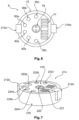
- a first interface 6 and a mechanical interface 7 are formed, which with respect to the Figures 6 and 8 be described in more detail.
- the interface 7 serves to attach the holding arm 1 to a base, such as in particular to an operating table.
- the interface 7 serves to transfer energy and to couple the holding arm 1 to an external control unit (see Fig. 5 ).
- a second interface 8 is provided at the distal end 4, via which a mechatronic assistance system and/or a surgical instrument, such as in particular a manipulator, can be coupled to the holding arm 1.
- a manipulator for holding and manipulating an endoscope is arranged here.
- the holding arm 1 has seven arm segments 10, 12, 14, 16, 18, 20, 22, each of which is essentially rod-shaped and, except for the last arm segment 22, all of which are essentially the same length.
- the seven arm segments 10, 12, 14, 16, 18, 20, 22 are each coupled to one another by joints 11, 13, 15, 17, 19, 21, 23, wherein the zeroth joint 11 connects the holding arm 1 to the base (in Fig. 1 not shown, see Fig. 7 ) is coupled.
- the joints 13, 15, 17, 19, 21, 23 are, according to this embodiment, all designed as rotary joints, each with one degree of freedom.
- the zeroth joint 11 is assigned to the zeroth segment 10
- the first joint 13 is assigned to the first arm segment 12
- the second joint 15 is assigned to the second arm segment 14
- the third joint 17 is assigned to the third arm segment 16
- the fourth joint 19 is assigned to the fourth arm joint 18
- the fifth joint 21 is assigned to the fifth arm segment 20
- the sixth joint 23 is assigned to the sixth arm segment 22.
- the joint 11 is designed as a translatory joint, so that the arm segment 10 can be extended telescopically in order to adjust the height of the holding arm 1, as will be explained later with reference to Figure 8 will be explained.
- the joints 13, 15, 17, 19, 21, and 23 each have pivot axes A1 , A2 , A3 , A4 , A5 , and A6 , with adjacent joints having pivot axes that are perpendicular to one another. This allows for easy positioning of the distal end 4 in space.
- the holding arm 1 further comprises an operating device 28.
- the operating device 28 By means of the operating device 28, the holding arm 1 can be moved into a desired position, wherein the operating device 28 is configured to release the associated joint upon contact between an operator and one of the seven arm segments.
- the operating device 28 according to this embodiment has seven contact sections 30, 32, 34, 36, 38, 40, 42, wherein a contact means 30, 32, 34, 36, 38, 40, 42 is arranged on each arm segment 10, 12, 14, 16, 18, 20, 22.
- a zeroth contact means 30 is arranged on the zeroth arm segment 10, a first contact means 32 on the first arm segment 12, a second contact means 34 on the second arm segment 14, a third contact means 36 on the third arm segment 16, a fourth contact means 38 on the fourth arm segment 18, a fifth contact means 40 on the fifth arm segment 20, and a sixth contact means 42 on the sixth arm segment 22.
- each contact means 30, 32, 34, 36, 38, 40, 42 comprises two contact means elements 30a, 30b, 32a, 32b, 34a, 34b, 36a, 36b, 38a, 38b, 40a, 40b, 42a, 42b arranged substantially opposite one another.
- the contact means 30, 32, 34, 36, 38, 40, 42 serve to detect contact of an operator with the corresponding arm segment 10, 12, 14, 16, 18, 20, 22. When gripping an arm segment 10, 12, 14, 16, 18, 20, 22, the operator comes into contact with both contact elements 30a, 30b to 42a, 42b, and only upon contact with both contact elements 30a, 30b to 42a, 42b of a contact element 30 to 42 is the associated joint released.
- the second contact means 34 has two contact means elements 34a, 34b, which are provided essentially opposite one another circumferentially on the arm segment 14.
- this contact is detected by the operating device 28, and the joint 15 assigned to the arm segment 14 is released.
- pivoting about the axis A 2 is possible, so that the distal end 4, relative to Figure 1 , can be pivoted up or down.
- all other joints 13, 17, 19, 21, and 23 remain locked, preventing any movement.
- the operating device 28 can have a controller or microprocessor which is configured to detect a contact between contact means elements 30a, 30b to 42a, 42b and to convert it into electrical signals.
- the contact means 30 or the contact means elements 30a, 30b to 42a, 42b are designed as touch-sensitive sensors and detect a pressure of contact between the operator and the corresponding contact means element 30a, 30b to 42a, 42b.
- the contact means elements 30a, 30b to 42a, 42b are designed as capacitive touch-sensitive sensors.
- the holding arm when two arm segments come into simultaneous contact—in this example, arm segments 14 and 18—not joints 15 and 19 are released, but rather all joints located between these arm segments 14 and 18, i.e., in this exemplary embodiment, joints 17 and 19. Joint 15 remains locked.
- the holding arm 1 can now be changed in its pose so that rotation about the axis A3 and the axis A4 is possible. This is a particularly intuitive operation of the holding arm. Accordingly, for example, upon contact between the operator and the holding arm segments 12 and 20, joints 15, 17, 19, and 21 are released.
- the holding arm 1 has a weight compensation device 50.
- the weight compensation device 50 comprises a gas pressure spring element which is coupled to the arm segment 14 and the arm segment 12.
- the weight compensation device can also comprise a cable pull and/or a balanced counterweight.
- the greatest moment is exerted on the joint 15 around its rotation axis A2. Consequently, it is preferable to support precisely this joint 15 by means of the weight compensation device 50.
- the holding arm 1 (cf. Fig. 2 ) has a recognition unit 52 for recognizing an assistance system coupled to the second interface 8, wherein the operating device 28 is adapted to release or lock the joints 11, 13, 15, 17, 19, 21, 23 depending on the assistance system coupled to the second interface 8.
- a recognition unit 52 preferably has a barcode scanner, a QR code scanner or an RFID scanner.
- an assistance system coupled to the second interface 8 is equipped with a corresponding barcode, QR code or an RFID chip, which contains an identification of the assistance system and preferably information about it.
- the holding arm 1 is able to recognize which assistance system is coupled to the second interface 8 and thus partially or completely prevent the release of certain joints 11, 13, 15, 17, 19, 21, 23.
- an endoscope is arranged at the second interface 8.
- the endoscope's RFID chip contains information about this endoscope, such as, in particular, the geometric dimensions of the endoscope. This information is recognized by the recognition unit and forwarded to the operating device 28 of the holding arm 1 and/or the external control unit.
- the operating device 28 is designed to prevent poses of the holding arm 1 in which the endoscope would collide with the holding arm. Furthermore, the operating device 28 can additionally be designed to prevent poses of the holding arm 1 in which the endoscope would collide with, for example, an operating table or other objects.
- Figure 2 are included in the holding arm 1 in addition to the Figure 1
- the brakes 60, 62, 64, 66, 68, 70, 72 are shown, by means of which the joints 11, 13, 15, 17, 19, 21, 23 can be released and locked.
- Identical and similar elements are given the same reference numerals as in Figure 1 and in this respect, reference is made in full to the above description. Even if in Figure 2 the reference numerals on the contact means elements of the contact means 30, 32, 34, 36, 38, 40, 42 are not shown for reasons of clarity, they are nevertheless present, as can be seen from a comparison of the Figures 1 and 2 results.
- Each joint 11, 13, 15, 17, 19, 21, and 23 is assigned a brake 60, 62, 64, 66, 68, 70, and 72, respectively.
- Brake 60 is assigned to joint 11, brake 62 to joint 13, brake 64 to joint 15, brake 66 to joint 17, brake 68 to joint 19, brake 70 to joint 21, and brake 72 to joint 23.
- All brakes 60 to 72 are electromagnetic brakes with a permanent magnet, such that they are preloaded into a locked state when deenergized.
- the permanent magnet is designed such that it can lock the respective joint on its own, maintaining the position of the holding arm 1.
- An electronic control unit 74 is provided in the zeroth arm segment 10. This is connected via a bus system 76 (in Figure 2 only shown in arm segment 10; cf. Fig.
- a power line 78 is also provided, which can be coupled to a power source via the interface 6 at the proximal end 2 of the holding arm 1.
- FIGS 3 and 4 show two different embodiments of an arm segment, where in the Figures 3 and 4
- the fourth arm segment 18 is shown as an example. It should be recognized that the other arm segments 10, 12, 14, 16, 20, 22 can also be designed in the same way.
- the arm segment 18 has an arm segment body 90 (in the Fig. 1 and 2 not shown; it should be understood that each arm segment 10 to 22 has an arm segment body) which, according to the Figures 3 and 4 is essentially rod-shaped or cylindrical. Inside, the arm segment body 90 has a cavity 92 in which various elements, such as the brake 70, are arranged. Schematically shown in the Figures 3 and 4 are the joints 19, 21 and the two pivot axes A 4 , A 5 of the joints 19, 21, which each interact with the holding arm segment 18. The joint 19 is assigned to the holding arm segment 18 (see above description of the Fig. 1 and 2 ).
- the arm segment body 90 has an outer surface 93 that is substantially cylindrical.
- the arm segment body 90 is formed, for example, from a metal such as, in particular, aluminum or titanium, an aluminum- or titanium-based alloy, or a fiber composite material such as GRP or CFRP, and is preferably designed as a lightweight construction.
- the arm segment 18 has, according to the Figures 3 and 4 the contact means 38, which is part of the operating device 28 (cf. Fig. 1 and 2 ).
- the contact means 38 has two contact means elements 38a, 38b, which are designed as touch-sensitive sensors and are arranged flush with the outer surface 93 of the arm segment 18.
- the two contact means elements 38a, 38b are arranged substantially opposite one another with respect to the axis A 5 , so that an operator comes into contact with both contact means elements 38a, 38b when gripping the arm segment 18, as described above.
- the two contact elements 38a, 38b are coupled to the bus system 76 via lines 94a, 94b.
- the contact elements 38a, 38b are connected to the electronic control unit 74 (see Fig. 2 ) and via this in turn with the brake 70, so that the brake 70 is released by the operating device 28 when an operator comes into contact with the contact means elements 38a, 38b.
- an energy transmission system 78 In addition to the bus system 76, an energy transmission system 78, a cable duct 80, and a working duct 82 are arranged within the arm segment body 90.
- the contact elements 38a, 38b and the brake 70 are connected to a power supply via the energy transmission system 78.
- an electronic module 96 is arranged in each arm segment, which is coupled to the bus system 76 via a line 96a.
- the contact elements 38a, 38b which are connected to the data bus system 76 via the line 94a, 94b, interact only with the electronic module 96, which converts the contact detected by the contact elements 38a, 38b into an actuating signal for the brake 70 and sends this actuating signal via the bus system 76 to the brake 70 to release the joint 19.
- an electronic module 96 is arranged in each arm segment, an essentially modular design of the holding arm 1 is realized, and the individual arm segments 10 to 22 are independent of the electronic control unit 74, which is arranged in the proximal arm segment 10.
- the cable channel 80 serves to guide cables that run from the proximal end 2 to the distal end 4, in particular to supply the interface 8.
- the working channel 82 serves to accommodate hoses or light guides and the like, which are required depending on the type of manipulator arranged at the interface 8. If, for example, an endoscope is arranged at the interface 8, a light guide is preferably guided through the working channel 82, which can transmit an image recorded by an endoscope camera.
- the working channel 82 therefore serves to accommodate appropriate transmission media depending on the area of application.
- a sensor 98 is arranged in the arm segment 18.
- a sensor is arranged in each arm segment 10 to 22, and it should be understood that the sensors in the arm segments 10, 12, 14, 16, 20, and 22 can be designed in the same way as the sensor 98 in the arm segment 18.
- the sensor 98 is preferably designed as an acceleration sensor. By providing such an acceleration sensor in each arm segment, it is possible to determine the pose of the holding arm 1 at any time.
- the sensor 98 is coupled to the data bus system 76 via a line 98a, so that the data acquired by the sensor 98 is transmitted to the electronic control unit 74, which then determines the pose of the holding arm 1 from all sensor data from all arm segments.
- the absolute and relative position of an end effector or manipulator arranged at the interface 8 can also be determined. It is also possible, if the support arm 1 is arranged on an operating table, to detect a movement of this operating table. If all sensors in all arm segments detect a movement in the same direction, this is an indicator that the entire support arm 1 has been moved while maintaining its position, for example, by the operating table or an operating table top being rotated or displaced relative to a column of the operating table. Such a movement can also be detected by the sensors 98. Furthermore, external impulses, such as impacts on the support arm 1, can be detected.
- the storage element serves to store electrical energy so that sensors provided in the specific arm segment can be supplied with power even when disconnected from the power grid. This is particularly necessary if, for example, bump sensors of a camera or the like are provided, which must also function when the holding arm is at rest in order to detect possible damage to the holding arm 1.
- the energy generation device 102 serves to provide energy for, for example, a laser, an ultrasound device, or the like, which are coupled to the holding arm. Additionally or alternatively, the energy generation device 102 can also have a device for supplying the storage element 100, for example an energy harvesting element, which converts kinetic energy or energy due to a magnetic field, for example inductively, into electrical voltage for the storage element 100.
- Figure 5 illustrates again the holding arm 1, which has already been described with reference to the Figures 1 and 2 has been described.
- the holding arm 1 is shown integrated into a system.
- a surgical mechatronic assistance system 200 is arranged by means of the interface 8, which is coupled to the interface 8 via an interface 201.
- Both the surgical mechatronic assistance system 200 and the interface 201 are in Figure 5 only shown schematically.
- the surgical mechatronic assistance system 200 can be designed, for example, as an endoscope or laparoscope or the like.
- the assistance system 200 has a working section 202, which can be, for example, the tip of the endoscope.
- the holding arm 1 is according to Figure 5 coupled to a base 204 via the mechanical interface 7.
- the base 204 is also shown only schematically here. It can be designed, for example, as a standard rail of an operating table.
- the first interface 6 is coupled to an external control unit 206.
- the interface 6 is connected to the external control unit 206 via a cable 208.
- the external control unit 206 is designed as an operating room system, which, for example, has a conventional computer and an input/output interface for operating the operating room system.
- the operating room system preferably has software components designed to store and process data transferred from the holding arm 1 to the interface 6.
- the interface 6 can also be provided that it communicates wirelessly with the surgical system 206, for example via Bluetooth ® , Wi-Fi ® or similar.
- the holding arm 1 further comprises a display 55, which according to this exemplary embodiment is designed as an LCD display.
- the display 55 is connected to a control unit and displays representations of data transferred to the first interface 6 or second interface 8.
- the weight of an assistance system 200 coupled to the interface 8 is displayed on the display.
- a representation of the pose of the holding arm is shown on the display, with corresponding loads on individual joints. Further possibilities are conceivable here. It is also conceivable that warnings are displayed here.
- the interface 6 (see Fig. 6 ) has a connection 77 for the bus system 76. Via this connection 77, data which is received from sensors (cf. Fig. 3 u. 4) and the contact elements (cf. Fig. 2 - 4 ) to the bus system 76, can be transmitted to the external control unit 206.
- the connection 77 can be designed as a USB interface, RS-232 interface, Bluetooth® interface, Wi- Fi® interface or the like.
- a connection 79 for transmitting electrical energy is also provided centrally at the interface 6. By means of this connection 79, the holding arm 1 can be coupled to an energy source, for example the power grid. Furthermore, at the interface 6, three outlets 80a, 80b, 80c of the cable duct 80 (cf.
- Cables which are guided into the cable duct 80 are accessible via these outlets 80a, 80b, 80c.
- three outlets 82a, 82b, 82c of the working channel 82 are provided in the interface 6.
- the working channel 82 is accessible via the outlets 82a, 82b, 82c.
- a hose can be guided through the outlet 82b into the working channel 82 via the interface 6 and through this to the distal interface 8 (cf. Fig. 10 ) can be carried out.
- Mechanical coupling means 210a, 210b are provided on a circumferential area of the arm segment 10 in the area of the interface 6.
- the coupling means 210a, 210b correspond to coupling means 212a, 212b of an external energy storage device 214 (see Fig. 7 ).
- the external energy storage device 214 has a housing 216 which is designed to be attached proximally to the arm segment 10.
- the external energy storage device 214 has cells inside for storing electrical energy (in Fig. 7 (not shown).
- the external energy storage device 214 has an interface 218 that corresponds to the interface 6 of the holding arm 1.
- the interface 218 has a connection 220, by means of which the electrical energy stored in the external energy storage device 214 can be transferred to the holding arm 1 via the connection 79 of the interface 6.
- the interface 218 has a connection 221, which corresponds to the interface 77, for passing through signals of the bus system 76.
- the external energy storage device has passages 222a, b, c, 224a, b, c, which correspond to the outlets 80a, b, c and 82a, b, c of the interface 6, so that cables guided through the cable duct 80 can also be guided through the energy storage device 214 and the outlets 82a, 82b, 82c of the working channel 80 are also accessible on the energy storage device 214.
- Fig. 8 illustrates the arm segment 10, which forms the proximal end 2 of the holding arm, and in particular the mechanical interface 7.
- the external energy storage device 214 (cf. Fig. 7 ) so that the holding arm 1 is arranged according to this embodiment ( Fig. 8 ) can be operated autonomously without the need to connect it to an external power source.
- a connection to a control unit 206 can nevertheless be provided and is preferred.
- the arm segment 10 has a contact means 30, which has two contact means sections 30a, 30b (see also Fig. 2 ).
- the interface 7 is formed according to this embodiment as a recess 226, which corresponds to the outer contour of the base 204, which is designed here as a standard rail of an operating table.
- the base 204 can be guided into the recess 226, and mechanical clamping means 228 are provided on the arm segment 10 for clamping the arm segment 10 against the base 204.
- the clamping means have a linearly guided clamping body 230, which is drivable via a linkage 232 with a lever 224.
- the joint 11, which can be released via the contact means 30 of the operating device 28, is consequently oriented as a translatory joint 11.
- the operating device is for this purpose via an electrical actuating means, which is in Figure 8 not shown, coupled to the lever 228 so that the clamping means 230 can be disengaged from the base 204.
- FIGS 9 and 10 finally illustrate the second interface 8 at the distal end 2 of the holding arm 1. While Figure 9 the interface 8 in a perspective view including the arm segment 22, Figure 10 the interface 8 in a frontal view.
- the interface 8 is designed essentially to correspond to the interface 6.
- Two securing elements 240a, 240b are arranged on the side sections of the interface, on the arm segment 22. By means of the securing elements, it can be determined whether an assistance system 200 coupled to the interface 8 (see Fig. 5 ) is correctly coupled to the interface 8.
- the securing elements 240a, 240b simultaneously serve as mechanical coupling means for mechanical coupling to the assistance system 200, for example by means of clamping or locking.
- connection 277 is arranged at interface 8, which corresponds to connection 77 of interface 6.
- Connection 277 is coupled to bus system 76, so that data and signals can be transmitted from connection 77 via bus system 76 to connection 77 and vice versa.
- a connection 279 is provided at interface 8, by means of which electrical energy can be transmitted from interface 8 to assistance system 200.
- Connection 279 corresponds to connection 79 of interface 6, and the two connections 279 and 79 are coupled by means of transmission means 78 for transmitting electrical energy between these two connections 79, 279.
- the Figures 11a and 11b show two further embodiments of the holding arm 1, which essentially corresponds to the first embodiment according to the Figures 1 and 2
- the holding arm has, according to the Figures 11a, 11b Alignment indicators 310, 312, 314, 316, 318, 320, 322, 330, 332, 334, 336, 338, 340, 342 respectively.
- the alignment indicators 310, 312, 314, 316, 318, 320, 322 are formed as a surface structure.
- the individual arm segments 10, 12, 14, 16, 18, 20, 22, which essentially have a cylindrical basic shape, have a structuring approximately along half of the cylinder surface.
- the structuring is arranged according to this embodiment such that the alignment indicators 310, 312, 314, 316, 318, 320, 322 of the holding arm 1 in a basic pose of the holding arm 1, as shown in Fig. 11a shown, are oriented toward the surgical field.
- the structuring which acts as an alignment indicator 310, 312, 314, 316, 318, 320, 322, allows an operator to tactilely determine whether an arm segment 10, 12, 14, 16, 18, 20, 22 is aligned in the basic pose, or whether the support arm is inverted, i.e., oriented with the structured surface away from the surgical field. This can be important for weight compensation.
- Fig. 11b An embodiment in which the alignment indicators 330, 332, 334, 336, 338, 340, 342 are designed as colored markings.
- a color gradient is provided on the sides of the arm segments 10, 12, 14, 16, 18, 20, 22 facing the surgical field, which is visually perceptible to a surgeon. This allows the surgeon to directly recognize the orientation of the holding arm 1.
- Fig. 12 shows a schematic partial sectional view of an exemplary brake, such as is provided, for example, as brake 64 in joint 15. It should be understood that the other brakes 60, 62, 66, 68, 70, 72 can also be designed accordingly.
- the brake 74 is, according to this embodiment ( Fig. 12 ) is designed as an electromagnetic permanent magnet brake.
- a first joint element 400 here as Shaft, is rigidly connected to the arm segment 12, and a second joint element 402 is rigidly connected to the arm segment 14. It should be understood that this can also be the other way around.
- the second joint element 402 is rigidly coupled to a housing 406 of the brake 64 via a screw 404.
- a flange hub 408 is correspondingly rigidly coupled to the first joint 400.
- a permanent magnet 410 is arranged in the housing 406, which serves to press an armature 412, which in turn is rigidly connected to the flange 408, against the housing 406. This creates static friction that acts as a braking force. Also arranged in the housing 406 is an excitation winding 414, which, when energized, creates a field that counteracts the field of the permanent magnet 410. A spring element 416, which preloads the armature 412 in a ventilated state, lifts the armature 412 from the housing 406, thus ventilating the brake 64. Rotation of the second joint element 402 about the first joint element 400 about the axis A2 is thus possible.
- Figure 13 shows a method 1000 for controlling a mechatronic assistance system 200 coupled to a support arm 1 according to the first exemplary embodiment.
- the method 1000 comprises five steps, which are carried out successively or partially simultaneously.
- the support arm 1 is attached to a standard rail of an operating table and put into operation.
- the first interface 4 is connected to an operating system 206 (see also Figure 5 ) so that data and electrical energy are transmitted at the first interface 6 to the holding arm 1.
- a mechatronic assistance system 200 is coupled to a second interface 8 of the holding arm 1 at its distal end 4.
- the following steps 1006 to 1010 are then preferably carried out simultaneously.
- step 1006 electrical energy and signals are transmitted from the first interface 6 of the holding arm 1 at a proximal end to the holding arm. From the first interface 6, the data and electrical energy are transmitted by means of a transmission device 76, 78 within the holding arm 1 to the second interface 8. At the second interface at the distal end, data and electrical energy are then transmitted to the assistance system in step 1010 so that the assistance system 200 can be operated.
- step 1010 positions of joints of the holding arm are detected.
Landscapes
- Health & Medical Sciences (AREA)
- Engineering & Computer Science (AREA)
- Life Sciences & Earth Sciences (AREA)
- Surgery (AREA)
- Nuclear Medicine, Radiotherapy & Molecular Imaging (AREA)
- Robotics (AREA)
- Public Health (AREA)
- Medical Informatics (AREA)
- Molecular Biology (AREA)
- Animal Behavior & Ethology (AREA)
- General Health & Medical Sciences (AREA)
- Biomedical Technology (AREA)
- Veterinary Medicine (AREA)
- Heart & Thoracic Surgery (AREA)
- Mechanical Engineering (AREA)
- Pathology (AREA)
- Human Computer Interaction (AREA)
- Oral & Maxillofacial Surgery (AREA)
- Radiology & Medical Imaging (AREA)
- Physics & Mathematics (AREA)
- Biophysics (AREA)
- Optics & Photonics (AREA)
- Multimedia (AREA)
- Gynecology & Obstetrics (AREA)
- Endoscopes (AREA)
- Manipulator (AREA)
Claims (13)
- Bras de support (1) à usage médical, en particulier pour supporter des systèmes d'assistance mécatroniques chirurgicaux et/ou des instruments chirurgicaux, comprenantune extrémité proximale (2) pour fixer le bras de support (1) à une base et une extrémité distale (4) pour recevoir un système d'assistance mécatronique chirurgical et/ou un instrument chirurgical;au moins un premier et un deuxième segments de bras (12, 14), le premier segment de bras (12) étant relié à une première articulation (13) et le deuxième segment de bras (14) étant relié à une deuxième articulation (15), chaque articulation (13, 15) pouvant être libérée et bloquée; etun dispositif de commande (28) pour amener le bras de support (1) dans une pose souhaitée,caractérisé en ce que le dispositif de commande (28) est conçu pour libérer l'articulation (13, 15) associée en cas de contact entre un opérateur et l'un des premier et deuxième segments de bras (12, 14), de sorte que la première articulation (13) est libérée en cas de contact entre un opérateur et le premier segment de bras (12) et la deuxième articulation (15) est libérée en cas de contact entre un opérateur et le deuxième segment de bras (14).
- Bras de support selon la revendication 1, le dispositif de commande (28) présentant des moyens de contact (30-42) qui sont prévus pour qu'un opérateur vienne en contact avec ceux-ci, un premier moyen de contact (32) du dispositif de commande (28) étant disposé sur le premier segment de bras (12) et un deuxième moyen de contact (34) étant disposé sur le deuxième segment de bras (14).
- Bras de support selon la revendication 2, chaque moyen de contact (30-42) présentant deux éléments de moyen de contact (30a, 30b-42a, 42b) disposés sensiblement l'un en face de l'autre sur le segment de bras (10-22).
- Bras de support selon la revendication 2 ou 3, les éléments centraux de contact (30a, 30b-42a, 42b) étant réalisés sous la forme de palpeurs ou de capteurs tactiles.
- Bras de support selon l'une des revendications précédentes, le dispositif de commande (28) étant configuré pour libérer l'articulation (11-23) associée en fonction de l'intensité du contact.
- Bras de support selon l'une des revendications précédentes, le dispositif de commande (28) libérant toutes les articulations (13, 15) disposées entre ces segments de bras en cas de contact entre l'opérateur et à la fois le premier et le deuxième segment de bras (12, 14).
- Bras de support selon l'une des revendications précédentes, les articulations (11-23) présentant des freins au moyen desquels les articulations (11-23) peuvent être libérées et bloquées, les freins étant de préférence réalisés sous la forme de freins électromagnétiques et présentant chacun un aimant permanent qui précontraint le frein dans l'état bloqué à l'état non alimenté.
- Bras de support selon l'une des revendications précédentes, comprenant une première interface (6) à l'extrémité proximale (2) pour connecter le bras de support (1) à une source d'énergie ainsi qu'à une unité de commande externe (206) pour transmettre des signaux vers et depuis le bras de support (1);une deuxième interface (8) à l'extrémité distale (4) pour coupler le bras de support (1) au système d'assistance (200) afin de commander le système d'assistance (200) ; etun dispositif de transmission (76, 78) qui est disposé à l'intérieur du bras de support (1) et qui relie la première interface (6) à la deuxième interface (8) pour transmettre de l'énergie et des signaux entre les interfaces (6, 8).
- Bras de support selon la revendication 8, le dispositif de transmission présentant un système de bus (76, 78).
- Bras de support selon l'une des revendications précédentes, au moins un segment de bras présentant un capteur pour détecter une position du segment de bras.
- Bras de support selon la revendication 8, comprenant une unité de reconnaissance pour reconnaître un système d'assistance couplé à la deuxième interface, le dispositif de commande (28) étant adapté pour libérer ou bloquer les articulations (11, 13, 15, 17, 19, 21, 23) en fonction du système d'assistance (200) couplé à la deuxième interface (8).
- Bras de support selon la revendication 8, comprenant une caméra qui est de préférence disposée à l'extrémité distale (4), la caméra étant prévue pour observer un champ opératoire et étant couplée à la première interface (6) pour transmettre des données d'image à la première interface (6).
- Bras de support selon la revendication 8, un élément de sécurité (240a, 240b) étant prévu au niveau de la deuxième interface (8), lequel est couplé au dispositif de commande (28) de sorte que le dispositif de commande (28) bloque toutes les articulations (11, 13, 15, 17, 19, 21, 23) lorsque l'élément de sécurité (240a, 240b) indique un couplage erroné entre le système d'assistance (200) et la deuxième interface (8).
Priority Applications (1)
| Application Number | Priority Date | Filing Date | Title |
|---|---|---|---|
| EP21205321.9A EP3995097B1 (fr) | 2014-11-14 | 2015-11-12 | Bras de retenue intelligent pour la chirurgie de la tête comprenant une commande tactile |
Applications Claiming Priority (3)
| Application Number | Priority Date | Filing Date | Title |
|---|---|---|---|
| DE102014016823.9A DE102014016823B4 (de) | 2014-11-14 | 2014-11-14 | Verfahren zum Steuern eines an einem Haltearm gekoppelten mechatronischen Assistenzsystems |
| DE102014016824.7A DE102014016824B4 (de) | 2014-11-14 | 2014-11-14 | Intelligenter Haltearm für die Kopfchirurgie mit berührungsempfindlicher Bedienung |
| PCT/EP2015/076446 WO2016075241A1 (fr) | 2014-11-14 | 2015-11-12 | Bras de support intelligent pour chirurgie de la tête avec commandes sensibles au contact |
Related Child Applications (2)
| Application Number | Title | Priority Date | Filing Date |
|---|---|---|---|
| EP21205321.9A Division-Into EP3995097B1 (fr) | 2014-11-14 | 2015-11-12 | Bras de retenue intelligent pour la chirurgie de la tête comprenant une commande tactile |
| EP21205321.9A Division EP3995097B1 (fr) | 2014-11-14 | 2015-11-12 | Bras de retenue intelligent pour la chirurgie de la tête comprenant une commande tactile |
Publications (2)
| Publication Number | Publication Date |
|---|---|
| EP3217909A1 EP3217909A1 (fr) | 2017-09-20 |
| EP3217909B1 true EP3217909B1 (fr) | 2025-05-07 |
Family
ID=54548157
Family Applications (2)
| Application Number | Title | Priority Date | Filing Date |
|---|---|---|---|
| EP21205321.9A Active EP3995097B1 (fr) | 2014-11-14 | 2015-11-12 | Bras de retenue intelligent pour la chirurgie de la tête comprenant une commande tactile |
| EP15795146.8A Active EP3217909B1 (fr) | 2014-11-14 | 2015-11-12 | Bras de support intelligent pour chirurgie de la tête avec commandes sensibles au contact |
Family Applications Before (1)
| Application Number | Title | Priority Date | Filing Date |
|---|---|---|---|
| EP21205321.9A Active EP3995097B1 (fr) | 2014-11-14 | 2015-11-12 | Bras de retenue intelligent pour la chirurgie de la tête comprenant une commande tactile |
Country Status (4)
| Country | Link |
|---|---|
| US (3) | US10426571B2 (fr) |
| EP (2) | EP3995097B1 (fr) |
| CA (1) | CA2966837C (fr) |
| WO (1) | WO2016075241A1 (fr) |
Families Citing this family (51)
| Publication number | Priority date | Publication date | Assignee | Title |
|---|---|---|---|---|
| JPWO2016152987A1 (ja) * | 2015-03-25 | 2018-01-18 | ソニー・オリンパスメディカルソリューションズ株式会社 | 医療用観察装置、手術用観察装置及び医療用観察システム |
| WO2016164824A1 (fr) | 2015-04-09 | 2016-10-13 | Auris Surgical Robotics, Inc. | Système chirurgical doté de bras mécaniques configurables montés sur rail |
| EP3269323B1 (fr) | 2015-08-12 | 2019-03-20 | medineering GmbH | Bras de support medical ayant des moyens d'affichage a del annulaires |
| WO2017103984A1 (fr) * | 2015-12-15 | 2017-06-22 | オリンパス株式会社 | Système de manipulation médicale et son procédé de fonctionnement |
| US10151606B1 (en) | 2016-02-24 | 2018-12-11 | Ommo Technologies, Inc. | Tracking position and movement using a magnetic field |
| GB2578513B (en) * | 2016-05-23 | 2020-11-18 | Imperial Innovations Ltd | Surgical instrument |
| JP6669865B2 (ja) * | 2016-07-19 | 2020-03-18 | オリンパス株式会社 | 医療デバイス保持装置 |
| CN106308946B (zh) * | 2016-08-17 | 2018-12-07 | 清华大学 | 一种应用于立体定向手术机器人的增强现实装置及其方法 |
| US11395709B2 (en) * | 2017-02-28 | 2022-07-26 | Sony Corporation | Control system, control method, and surgical arm system |
| AU2018201287B2 (en) * | 2017-03-07 | 2019-01-03 | Stryker Corporation | Medical multi-link boom |
| EP3199106B1 (fr) * | 2017-04-26 | 2020-09-09 | Siemens Healthcare GmbH | Procédé et dispositif destinés à l'examen par ultrasons |
| DE102017111302A1 (de) * | 2017-05-23 | 2018-11-29 | Medineering Gmbh | Medizinische mechatronische männliche sowie weibliche Schnittstelleneinrichtung |
| JP2018202504A (ja) * | 2017-05-31 | 2018-12-27 | ソニー株式会社 | 医療用支持アームシステム、医療用支持アームの制御方法、および医療用支持アームの制御装置 |
| JP2018202032A (ja) * | 2017-06-08 | 2018-12-27 | 株式会社メディカロイド | 医療器具の遠隔操作装置 |
| JP6633580B2 (ja) * | 2017-08-02 | 2020-01-22 | ファナック株式会社 | ロボットシステム及びロボット制御装置 |
| CN108145713B (zh) * | 2017-12-29 | 2020-10-16 | 微创(上海)医疗机器人有限公司 | 机械臂、其控制方法及手术机器人 |
| KR102414011B1 (ko) * | 2017-12-29 | 2022-06-27 | 더 보드 오브 리젠츠 오브 더 유니버시티 오브 텍사스 시스템 | 수술 기구 및 피복의 단부상에서의 캡에 대한 엔드 이펙터의 위치결정 방법 |
| CA3085476A1 (fr) * | 2018-01-04 | 2019-07-11 | Covidien Lp | Systemes et ensembles pour monter un accessoire chirurgical sur des systemes chirurgicaux robotiques, et fournir un acces a travers ceux-ci |
| KR102264368B1 (ko) | 2018-01-17 | 2021-06-17 | 아우리스 헬스, 인코포레이티드 | 조절가능 아암 지지부를 갖는 수술 플랫폼 |
| CN108673556B (zh) * | 2018-07-18 | 2024-06-04 | 深圳熙康医疗科技有限公司 | 一种机械臂 |
| EP3628265A1 (fr) * | 2018-09-25 | 2020-04-01 | W & H Dentalwerk Bürmoos GmbH | Instrument de traitement médical ou dentaire pouvant être tenu à la main doté d'un capteur capacitif |
| CN113286548A (zh) | 2018-12-21 | 2021-08-20 | 史密夫和内修有限公司 | 具有张力反馈的致动牵开器 |
| US20220110685A1 (en) | 2019-02-05 | 2022-04-14 | Smith & Nephew, Inc. | Methods for improving robotic surgical systems and devices thereof |
| US11202683B2 (en) | 2019-02-22 | 2021-12-21 | Auris Health, Inc. | Surgical platform with motorized arms for adjustable arm supports |
| WO2020185516A1 (fr) | 2019-03-08 | 2020-09-17 | Auris Health, Inc. | Mécanismes d'inclinaison pour applications et systèmes médicaux |
| JP6867654B2 (ja) * | 2019-03-15 | 2021-05-12 | リバーフィールド株式会社 | 医用ロボットシステムの力覚表示装置および力覚表示方法 |
| WO2020206216A1 (fr) | 2019-04-05 | 2020-10-08 | Smith & Nephew, Inc. | Procédés et système de fabrication d'un implant d'articulation |
| RU2705018C9 (ru) * | 2019-04-22 | 2019-12-12 | Николай Александрович Корюшенков | Устройство переключения режимов работы динамического пилона |
| US11272989B2 (en) | 2019-04-29 | 2022-03-15 | Smith & Nephew, Inc. | Multi-level positional tracking |
| US11389304B1 (en) | 2019-05-06 | 2022-07-19 | Smith & Nephew, Inc. | Devices, systems and methods for providing instrument orientation feedback |
| WO2020240270A1 (fr) | 2019-05-31 | 2020-12-03 | Mubarak Muhamed Khan | Appareil pour maintenir un endoscope |
| US12245900B2 (en) | 2019-06-03 | 2025-03-11 | Covidien Lp | System and apparatus for external torque observation and compensation for surgical robotic arm |
| US12144551B1 (en) | 2019-06-26 | 2024-11-19 | Smith & Nephew, Inc. | Computer-assisted tissue navigation |
| US12127791B1 (en) | 2019-07-08 | 2024-10-29 | Smith & Nephew, Inc. | Simulation-enhanced intraoperative surgical planning tool for robotics-assisted total knee arthroplasty |
| CN114466625B (zh) | 2019-10-03 | 2026-04-10 | 史密夫和内修有限公司 | 全膝关节置换翻修术期间的髓内管的配准 |
| US11517334B1 (en) | 2019-11-04 | 2022-12-06 | Smith & Nephew, Inc. | Patient-specific guides for latarjet procedure |
| GB2589376B (en) * | 2019-11-29 | 2023-11-08 | Cmr Surgical Ltd | Detecting a trigger in a surgical robotic system |
| WO2021112193A1 (fr) * | 2019-12-05 | 2021-06-10 | 川崎重工業株式会社 | Système d'opération chirurgicale et procédé de commande de bras de manipulateur d'opération chirurgicale |
| CN115697241A (zh) * | 2020-06-16 | 2023-02-03 | 直观外科手术操作公司 | 用于在计算机辅助系统中选择性的关节浮动的技术 |
| CN116322550A (zh) * | 2020-09-30 | 2023-06-23 | 奥瑞斯健康公司 | 机器人外科手术中用于术中患者定位的引导协调式床运动 |
| WO2022184071A1 (fr) * | 2021-03-02 | 2022-09-09 | 上海微创医疗机器人(集团)股份有限公司 | Bras robotisé, dispositif chirurgical, dispositif d'extrémité chirurgicale, système chirurgical et procédé de travail |
| WO2023286066A1 (fr) * | 2021-07-15 | 2023-01-19 | Momentis Surgical Ltd | Bras d'entrée pour la commande d'un bras chirurgical |
| CN113648066B (zh) * | 2021-08-20 | 2022-10-11 | 苏州康多机器人有限公司 | 一种碰撞检测方法、电子设备及主从手术机器人 |
| WO2023059589A1 (fr) | 2021-10-05 | 2023-04-13 | Smith & Nephew, Inc. | Systèmes de guide de coupe |
| WO2023064433A1 (fr) | 2021-10-13 | 2023-04-20 | Smith & Nephew, Inc. | Procédés d'alignement et de suivi chirurgical à l'aide de dispositifs d'imagerie hybrides et systèmes associés |
| US11963733B2 (en) | 2021-12-01 | 2024-04-23 | Nuvasive Inc. | Connector assemblies for connecting a robotic arm with a medical end effector |
| CN115177370B (zh) * | 2022-07-19 | 2023-08-04 | 苏州大学附属儿童医院 | 一种多功能外科手术用护理装置及其使用方法 |
| US12611268B2 (en) * | 2023-05-31 | 2026-04-28 | Auris Health, Inc. | Brake release for surgical robot |
| CN116852351A (zh) * | 2023-06-13 | 2023-10-10 | 敏捷医疗科技(苏州)有限公司 | 手术机器人的手术臂控制方法及手术机器人 |
| WO2025154067A1 (fr) * | 2024-01-16 | 2025-07-24 | Mazor Robotics Ltd. | Systèmes et procédés permettant de fixer un changeur d'outil à un bras robotique |
| WO2026080426A1 (fr) | 2024-10-10 | 2026-04-16 | Smith & Nephew, Inc. | Interface utilisateur de cartographie colorimétrique dynamique de contact implant-os lors de la pose peropératoire d'implant |
Citations (2)
| Publication number | Priority date | Publication date | Assignee | Title |
|---|---|---|---|---|
| US20020177857A1 (en) * | 2001-05-22 | 2002-11-28 | Olympus Optical Co., Ltd. | Surgery equipment holding device |
| US20120283747A1 (en) * | 2009-11-16 | 2012-11-08 | Koninklijke Philips Electronics N.V. | Human-robot shared control for endoscopic assistant robot |
Family Cites Families (15)
| Publication number | Priority date | Publication date | Assignee | Title |
|---|---|---|---|---|
| DE19526915B4 (de) | 1995-07-24 | 2004-05-06 | Aesculap Ag & Co. Kg | Haltevorrichtung für chirurgische Zwecke |
| US7347849B2 (en) * | 2001-05-24 | 2008-03-25 | Nxstage Medical, Inc. | Modular medical treatment replaceable component |
| US7831292B2 (en) * | 2002-03-06 | 2010-11-09 | Mako Surgical Corp. | Guidance system and method for surgical procedures with improved feedback |
| JP2004209096A (ja) * | 2003-01-07 | 2004-07-29 | Olympus Corp | 医療用器具保持装置 |
| JP2005013715A (ja) | 2003-06-05 | 2005-01-20 | Olympus Corp | 観察システム |
| JP4559093B2 (ja) * | 2003-10-03 | 2010-10-06 | オリンパス株式会社 | 医療用具支持装置 |
| US20050209614A1 (en) * | 2004-03-04 | 2005-09-22 | Fenter Felix W | Anastomosis apparatus and methods with computer-aided, automated features |
| DE102004050714A1 (de) | 2004-10-19 | 2006-04-20 | Claumas Gmbh | Vorrichtung zum Halten eines Instruments während einer Operation |
| US8160743B2 (en) * | 2005-08-16 | 2012-04-17 | Brainlab Ag | Anthropomorphic medical robot arm with movement restrictions |
| DE102007006891A1 (de) | 2007-02-13 | 2008-08-14 | University Of Dundee | Haltevorrichtung für medizinische Zwecke |
| DE102008059331B4 (de) | 2008-11-27 | 2012-05-31 | Siemens Aktiengesellschaft | Stativ, insbesondere Bodenstativ |
| US8632064B2 (en) * | 2009-07-15 | 2014-01-21 | The Board Of Trustees Of The Leland Stanford Junior University | Positioning apparatus with lockable joints and method of use |
| GB2472066A (en) * | 2009-07-23 | 2011-01-26 | Medi Maton Ltd | Device for manipulating and tracking a guide tube with radiopaque markers |
| DE102011004926A1 (de) * | 2011-03-01 | 2012-09-06 | Karl Storz Gmbh & Co. Kg | Einstellbare Haltevorrichtung für ein Endoskop |
| JP6512216B2 (ja) * | 2014-03-14 | 2019-05-15 | ソニー株式会社 | ロボットアーム装置、ロボットアーム制御方法及びプログラム |
-
2015
- 2015-11-12 CA CA2966837A patent/CA2966837C/fr active Active
- 2015-11-12 US US15/525,585 patent/US10426571B2/en active Active
- 2015-11-12 EP EP21205321.9A patent/EP3995097B1/fr active Active
- 2015-11-12 EP EP15795146.8A patent/EP3217909B1/fr active Active
- 2015-11-12 WO PCT/EP2015/076446 patent/WO2016075241A1/fr not_active Ceased
-
2019
- 2019-09-03 US US16/559,591 patent/US11589951B2/en active Active
-
2023
- 2023-01-25 US US18/101,157 patent/US20230233283A1/en active Pending
Patent Citations (2)
| Publication number | Priority date | Publication date | Assignee | Title |
|---|---|---|---|---|
| US20020177857A1 (en) * | 2001-05-22 | 2002-11-28 | Olympus Optical Co., Ltd. | Surgery equipment holding device |
| US20120283747A1 (en) * | 2009-11-16 | 2012-11-08 | Koninklijke Philips Electronics N.V. | Human-robot shared control for endoscopic assistant robot |
Also Published As
| Publication number | Publication date |
|---|---|
| US20230233283A1 (en) | 2023-07-27 |
| CA2966837A1 (fr) | 2016-05-19 |
| US10426571B2 (en) | 2019-10-01 |
| EP3995097B1 (fr) | 2022-09-21 |
| US20180289445A1 (en) | 2018-10-11 |
| CA2966837C (fr) | 2023-03-28 |
| US11589951B2 (en) | 2023-02-28 |
| EP3995097A1 (fr) | 2022-05-11 |
| WO2016075241A1 (fr) | 2016-05-19 |
| EP3217909A1 (fr) | 2017-09-20 |
| US20190388179A1 (en) | 2019-12-26 |
Similar Documents
| Publication | Publication Date | Title |
|---|---|---|
| EP3217909B1 (fr) | Bras de support intelligent pour chirurgie de la tête avec commandes sensibles au contact | |
| DE102014016823B4 (de) | Verfahren zum Steuern eines an einem Haltearm gekoppelten mechatronischen Assistenzsystems | |
| EP3273897B1 (fr) | Procédé et dispositif pour assurer la commande d'un système d'assistance mécatronique chirurgical au moyen d'un bras de retenue à usage médical | |
| EP3273900B1 (fr) | Bras de retenue à usage médical équipé d'un dispositif de commande amovible, et dispositif de commande de celui-ci | |
| DE102014016824B4 (de) | Intelligenter Haltearm für die Kopfchirurgie mit berührungsempfindlicher Bedienung | |
| EP2449997B1 (fr) | Poste de travail médical | |
| EP2415417B1 (fr) | Poste de travail médical | |
| WO2015049095A1 (fr) | Dispositif de commande et procédé permettant de commander un système de robot par commande gestuelle | |
| EP1686912A2 (fr) | Plateforme actrice destinee a guider des effecteurs terminaux lors d'interventions a effraction minimale | |
| DE102019201277A1 (de) | Vorrichtung zur Führung eines medizinischen flexiblen Schafts | |
| DE102014019752B4 (de) | Haltearm für medizinische Zwecke mit zwei mechatronischen Schnittstellen | |
| EP3515277B1 (fr) | Bras de retenue médical destiné à être intégré dans un système de navigation opératoire | |
| DE102019128277B4 (de) | Passive Haltevorrichtung, modulares chirurgisches System und Verfahren zum Handhaben eines Trokars | |
| WO2018215221A1 (fr) | Manipulateur robotique pour guider un endoscope avec une cinématique parallèle | |
| EP3273898B1 (fr) | Instrument chirurgical et système | |
| DE102022118388B4 (de) | Chirurgiesystem für die minimalinvasive robotische Chirurgie | |
| DE102018104714A1 (de) | Telemanipulatorsystem und Verfahren zum Betreiben eines Telemanipulatorsystems | |
| DE102025127143A1 (de) | Ausrichtungsversatz für das nachführen des instruments zur ergonomischen manipulatorsteuerung durch den chirurgen | |
| WO2026077943A1 (fr) | Dispositif d'axe linéaire pour un robot, robot et procédé de déplacement linéaire robotique d'un instrument |
Legal Events
| Date | Code | Title | Description |
|---|---|---|---|
| STAA | Information on the status of an ep patent application or granted ep patent |
Free format text: STATUS: THE INTERNATIONAL PUBLICATION HAS BEEN MADE |
|
| PUAI | Public reference made under article 153(3) epc to a published international application that has entered the european phase |
Free format text: ORIGINAL CODE: 0009012 |
|
| STAA | Information on the status of an ep patent application or granted ep patent |
Free format text: STATUS: REQUEST FOR EXAMINATION WAS MADE |
|
| 17P | Request for examination filed |
Effective date: 20170614 |
|
| AK | Designated contracting states |
Kind code of ref document: A1 Designated state(s): AL AT BE BG CH CY CZ DE DK EE ES FI FR GB GR HR HU IE IS IT LI LT LU LV MC MK MT NL NO PL PT RO RS SE SI SK SM TR |
|
| AX | Request for extension of the european patent |
Extension state: BA ME |
|
| DAV | Request for validation of the european patent (deleted) | ||
| DAX | Request for extension of the european patent (deleted) | ||
| STAA | Information on the status of an ep patent application or granted ep patent |
Free format text: STATUS: EXAMINATION IS IN PROGRESS |
|
| 17Q | First examination report despatched |
Effective date: 20190626 |
|
| RAP3 | Party data changed (applicant data changed or rights of an application transferred) |
Owner name: BRAINLAB ROBOTICS GMBH |
|
| RIC1 | Information provided on ipc code assigned before grant |
Ipc: A61B 90/50 20160101AFI20210521BHEP Ipc: A61B 34/00 20160101ALI20210521BHEP Ipc: B25J 13/08 20060101ALI20210521BHEP Ipc: B25J 19/00 20060101ALI20210521BHEP Ipc: A61B 1/00 20060101ALI20210521BHEP Ipc: A61B 90/00 20160101ALN20210521BHEP |
|
| GRAP | Despatch of communication of intention to grant a patent |
Free format text: ORIGINAL CODE: EPIDOSNIGR1 |
|
| STAA | Information on the status of an ep patent application or granted ep patent |
Free format text: STATUS: GRANT OF PATENT IS INTENDED |
|
| RIC1 | Information provided on ipc code assigned before grant |
Ipc: A61B 90/50 20160101AFI20210611BHEP Ipc: A61B 34/00 20160101ALI20210611BHEP Ipc: B25J 13/08 20060101ALI20210611BHEP Ipc: B25J 19/00 20060101ALI20210611BHEP Ipc: A61B 1/00 20060101ALI20210611BHEP Ipc: A61B 90/00 20160101ALN20210611BHEP |
|
| INTG | Intention to grant announced |
Effective date: 20210714 |
|
| GRAJ | Information related to disapproval of communication of intention to grant by the applicant or resumption of examination proceedings by the epo deleted |
Free format text: ORIGINAL CODE: EPIDOSDIGR1 |
|
| STAA | Information on the status of an ep patent application or granted ep patent |
Free format text: STATUS: EXAMINATION IS IN PROGRESS |
|
| INTC | Intention to grant announced (deleted) | ||
| APBK | Appeal reference recorded |
Free format text: ORIGINAL CODE: EPIDOSNREFNE |
|
| APBN | Date of receipt of notice of appeal recorded |
Free format text: ORIGINAL CODE: EPIDOSNNOA2E |
|
| APBR | Date of receipt of statement of grounds of appeal recorded |
Free format text: ORIGINAL CODE: EPIDOSNNOA3E |
|
| APAF | Appeal reference modified |
Free format text: ORIGINAL CODE: EPIDOSCREFNE |
|
| APBT | Appeal procedure closed |
Free format text: ORIGINAL CODE: EPIDOSNNOA9E |
|
| REG | Reference to a national code |
Ref country code: DE Ref legal event code: R079 Free format text: PREVIOUS MAIN CLASS: A61B0034000000 Ipc: A61B0090500000 Ref document number: 502015017079 Country of ref document: DE |
|
| GRAP | Despatch of communication of intention to grant a patent |
Free format text: ORIGINAL CODE: EPIDOSNIGR1 |
|
| STAA | Information on the status of an ep patent application or granted ep patent |
Free format text: STATUS: GRANT OF PATENT IS INTENDED |
|
| RIC1 | Information provided on ipc code assigned before grant |
Ipc: A61B 90/00 20160101ALN20241212BHEP Ipc: A61B 1/00 20060101ALI20241212BHEP Ipc: B25J 19/00 20060101ALI20241212BHEP Ipc: B25J 13/08 20060101ALI20241212BHEP Ipc: A61B 34/00 20160101ALI20241212BHEP Ipc: A61B 90/50 20160101AFI20241212BHEP |
|
| INTG | Intention to grant announced |
Effective date: 20241220 |
|
| P01 | Opt-out of the competence of the unified patent court (upc) registered |
Free format text: CASE NUMBER: APP_7052/2025 Effective date: 20250211 |
|
| GRAS | Grant fee paid |
Free format text: ORIGINAL CODE: EPIDOSNIGR3 |
|
| GRAA | (expected) grant |
Free format text: ORIGINAL CODE: 0009210 |
|
| STAA | Information on the status of an ep patent application or granted ep patent |
Free format text: STATUS: THE PATENT HAS BEEN GRANTED |
|
| AK | Designated contracting states |
Kind code of ref document: B1 Designated state(s): AL AT BE BG CH CY CZ DE DK EE ES FI FR GB GR HR HU IE IS IT LI LT LU LV MC MK MT NL NO PL PT RO RS SE SI SK SM TR |
|
| REG | Reference to a national code |
Ref country code: GB Ref legal event code: FG4D Free format text: NOT ENGLISH |
|
| REG | Reference to a national code |
Ref country code: CH Ref legal event code: EP |
|
| REG | Reference to a national code |
Ref country code: DE Ref legal event code: R096 Ref document number: 502015017079 Country of ref document: DE |
|
| REG | Reference to a national code |
Ref country code: IE Ref legal event code: FG4D Free format text: LANGUAGE OF EP DOCUMENT: GERMAN |
|
| REG | Reference to a national code |
Ref country code: NL Ref legal event code: MP Effective date: 20250507 |
|
| PG25 | Lapsed in a contracting state [announced via postgrant information from national office to epo] |
Ref country code: PT Free format text: LAPSE BECAUSE OF FAILURE TO SUBMIT A TRANSLATION OF THE DESCRIPTION OR TO PAY THE FEE WITHIN THE PRESCRIBED TIME-LIMIT Effective date: 20250908 Ref country code: FI Free format text: LAPSE BECAUSE OF FAILURE TO SUBMIT A TRANSLATION OF THE DESCRIPTION OR TO PAY THE FEE WITHIN THE PRESCRIBED TIME-LIMIT Effective date: 20250507 Ref country code: ES Free format text: LAPSE BECAUSE OF FAILURE TO SUBMIT A TRANSLATION OF THE DESCRIPTION OR TO PAY THE FEE WITHIN THE PRESCRIBED TIME-LIMIT Effective date: 20250507 |
|
| REG | Reference to a national code |
Ref country code: LT Ref legal event code: MG9D |
|
| PG25 | Lapsed in a contracting state [announced via postgrant information from national office to epo] |
Ref country code: NO Free format text: LAPSE BECAUSE OF FAILURE TO SUBMIT A TRANSLATION OF THE DESCRIPTION OR TO PAY THE FEE WITHIN THE PRESCRIBED TIME-LIMIT Effective date: 20250807 Ref country code: GR Free format text: LAPSE BECAUSE OF FAILURE TO SUBMIT A TRANSLATION OF THE DESCRIPTION OR TO PAY THE FEE WITHIN THE PRESCRIBED TIME-LIMIT Effective date: 20250808 |
|
| PG25 | Lapsed in a contracting state [announced via postgrant information from national office to epo] |
Ref country code: NL Free format text: LAPSE BECAUSE OF FAILURE TO SUBMIT A TRANSLATION OF THE DESCRIPTION OR TO PAY THE FEE WITHIN THE PRESCRIBED TIME-LIMIT Effective date: 20250507 Ref country code: PL Free format text: LAPSE BECAUSE OF FAILURE TO SUBMIT A TRANSLATION OF THE DESCRIPTION OR TO PAY THE FEE WITHIN THE PRESCRIBED TIME-LIMIT Effective date: 20250507 |
|
| PG25 | Lapsed in a contracting state [announced via postgrant information from national office to epo] |
Ref country code: BG Free format text: LAPSE BECAUSE OF FAILURE TO SUBMIT A TRANSLATION OF THE DESCRIPTION OR TO PAY THE FEE WITHIN THE PRESCRIBED TIME-LIMIT Effective date: 20250507 |
|
| PG25 | Lapsed in a contracting state [announced via postgrant information from national office to epo] |
Ref country code: HR Free format text: LAPSE BECAUSE OF FAILURE TO SUBMIT A TRANSLATION OF THE DESCRIPTION OR TO PAY THE FEE WITHIN THE PRESCRIBED TIME-LIMIT Effective date: 20250507 |
|
| PG25 | Lapsed in a contracting state [announced via postgrant information from national office to epo] |
Ref country code: RS Free format text: LAPSE BECAUSE OF FAILURE TO SUBMIT A TRANSLATION OF THE DESCRIPTION OR TO PAY THE FEE WITHIN THE PRESCRIBED TIME-LIMIT Effective date: 20250807 |
|
| PG25 | Lapsed in a contracting state [announced via postgrant information from national office to epo] |
Ref country code: IS Free format text: LAPSE BECAUSE OF FAILURE TO SUBMIT A TRANSLATION OF THE DESCRIPTION OR TO PAY THE FEE WITHIN THE PRESCRIBED TIME-LIMIT Effective date: 20250907 |
|
| PG25 | Lapsed in a contracting state [announced via postgrant information from national office to epo] |
Ref country code: LV Free format text: LAPSE BECAUSE OF FAILURE TO SUBMIT A TRANSLATION OF THE DESCRIPTION OR TO PAY THE FEE WITHIN THE PRESCRIBED TIME-LIMIT Effective date: 20250507 |
|
| PGFP | Annual fee paid to national office [announced via postgrant information from national office to epo] |
Ref country code: DE Payment date: 20251201 Year of fee payment: 11 |
|
| PG25 | Lapsed in a contracting state [announced via postgrant information from national office to epo] |
Ref country code: SM Free format text: LAPSE BECAUSE OF FAILURE TO SUBMIT A TRANSLATION OF THE DESCRIPTION OR TO PAY THE FEE WITHIN THE PRESCRIBED TIME-LIMIT Effective date: 20250507 Ref country code: DK Free format text: LAPSE BECAUSE OF FAILURE TO SUBMIT A TRANSLATION OF THE DESCRIPTION OR TO PAY THE FEE WITHIN THE PRESCRIBED TIME-LIMIT Effective date: 20250507 |
|
| PGFP | Annual fee paid to national office [announced via postgrant information from national office to epo] |
Ref country code: FR Payment date: 20251120 Year of fee payment: 11 |
|
| PG25 | Lapsed in a contracting state [announced via postgrant information from national office to epo] |
Ref country code: CZ Free format text: LAPSE BECAUSE OF FAILURE TO SUBMIT A TRANSLATION OF THE DESCRIPTION OR TO PAY THE FEE WITHIN THE PRESCRIBED TIME-LIMIT Effective date: 20250507 |
|
| PG25 | Lapsed in a contracting state [announced via postgrant information from national office to epo] |
Ref country code: EE Free format text: LAPSE BECAUSE OF FAILURE TO SUBMIT A TRANSLATION OF THE DESCRIPTION OR TO PAY THE FEE WITHIN THE PRESCRIBED TIME-LIMIT Effective date: 20250507 |
|
| PG25 | Lapsed in a contracting state [announced via postgrant information from national office to epo] |
Ref country code: SK Free format text: LAPSE BECAUSE OF FAILURE TO SUBMIT A TRANSLATION OF THE DESCRIPTION OR TO PAY THE FEE WITHIN THE PRESCRIBED TIME-LIMIT Effective date: 20250507 Ref country code: RO Free format text: LAPSE BECAUSE OF FAILURE TO SUBMIT A TRANSLATION OF THE DESCRIPTION OR TO PAY THE FEE WITHIN THE PRESCRIBED TIME-LIMIT Effective date: 20250507 |
|
| PG25 | Lapsed in a contracting state [announced via postgrant information from national office to epo] |
Ref country code: IT Free format text: LAPSE BECAUSE OF FAILURE TO SUBMIT A TRANSLATION OF THE DESCRIPTION OR TO PAY THE FEE WITHIN THE PRESCRIBED TIME-LIMIT Effective date: 20250507 |
|
| REG | Reference to a national code |
Ref country code: DE Ref legal event code: R097 Ref document number: 502015017079 Country of ref document: DE |
|
| PLBE | No opposition filed within time limit |
Free format text: ORIGINAL CODE: 0009261 |
|
| STAA | Information on the status of an ep patent application or granted ep patent |
Free format text: STATUS: NO OPPOSITION FILED WITHIN TIME LIMIT |
|
| REG | Reference to a national code |
Ref country code: CH Ref legal event code: L10 Free format text: ST27 STATUS EVENT CODE: U-0-0-L10-L00 (AS PROVIDED BY THE NATIONAL OFFICE) Effective date: 20260318 |
|
| 26N | No opposition filed |
Effective date: 20260210 |