EP3273897B1 - Procédé et dispositif pour assurer la commande d'un système d'assistance mécatronique chirurgical au moyen d'un bras de retenue à usage médical - Google Patents
Procédé et dispositif pour assurer la commande d'un système d'assistance mécatronique chirurgical au moyen d'un bras de retenue à usage médical Download PDFInfo
- Publication number
- EP3273897B1 EP3273897B1 EP16711825.6A EP16711825A EP3273897B1 EP 3273897 B1 EP3273897 B1 EP 3273897B1 EP 16711825 A EP16711825 A EP 16711825A EP 3273897 B1 EP3273897 B1 EP 3273897B1
- Authority
- EP
- European Patent Office
- Prior art keywords
- arm
- holding arm
- assistance system
- assistance
- request signal
- Prior art date
- Legal status (The legal status is an assumption and is not a legal conclusion. Google has not performed a legal analysis and makes no representation as to the accuracy of the status listed.)
- Active
Links
Images



Classifications
-
- A—HUMAN NECESSITIES
- A61—MEDICAL OR VETERINARY SCIENCE; HYGIENE
- A61B—DIAGNOSIS; SURGERY; IDENTIFICATION
- A61B90/00—Instruments, implements or accessories specially adapted for surgery or diagnosis and not covered by any of the groups A61B1/00 - A61B50/00, e.g. for luxation treatment or for protecting wound edges
- A61B90/50—Supports for surgical instruments, e.g. articulated arms
-
- A—HUMAN NECESSITIES
- A61—MEDICAL OR VETERINARY SCIENCE; HYGIENE
- A61B—DIAGNOSIS; SURGERY; IDENTIFICATION
- A61B1/00—Instruments for performing medical examinations of the interior of cavities or tubes of the body by visual or photographical inspection, e.g. endoscopes; Illuminating arrangements therefor
- A61B1/00147—Holding or positioning arrangements
- A61B1/00149—Holding or positioning arrangements using articulated arms
-
- A—HUMAN NECESSITIES
- A61—MEDICAL OR VETERINARY SCIENCE; HYGIENE
- A61B—DIAGNOSIS; SURGERY; IDENTIFICATION
- A61B90/00—Instruments, implements or accessories specially adapted for surgery or diagnosis and not covered by any of the groups A61B1/00 - A61B50/00, e.g. for luxation treatment or for protecting wound edges
- A61B90/36—Image-producing devices or illumination devices not otherwise provided for
- A61B90/37—Surgical systems with images on a monitor during operation
-
- A—HUMAN NECESSITIES
- A61—MEDICAL OR VETERINARY SCIENCE; HYGIENE
- A61B—DIAGNOSIS; SURGERY; IDENTIFICATION
- A61B17/00—Surgical instruments, devices or methods
- A61B2017/00017—Electrical control of surgical instruments
- A61B2017/00115—Electrical control of surgical instruments with audible or visual output
-
- A—HUMAN NECESSITIES
- A61—MEDICAL OR VETERINARY SCIENCE; HYGIENE
- A61B—DIAGNOSIS; SURGERY; IDENTIFICATION
- A61B17/00—Surgical instruments, devices or methods
- A61B2017/00017—Electrical control of surgical instruments
- A61B2017/00207—Electrical control of surgical instruments with hand gesture control or hand gesture recognition
-
- A—HUMAN NECESSITIES
- A61—MEDICAL OR VETERINARY SCIENCE; HYGIENE
- A61B—DIAGNOSIS; SURGERY; IDENTIFICATION
- A61B90/00—Instruments, implements or accessories specially adapted for surgery or diagnosis and not covered by any of the groups A61B1/00 - A61B50/00, e.g. for luxation treatment or for protecting wound edges
- A61B90/50—Supports for surgical instruments, e.g. articulated arms
- A61B2090/508—Supports for surgical instruments, e.g. articulated arms with releasable brake mechanisms
-
- A—HUMAN NECESSITIES
- A61—MEDICAL OR VETERINARY SCIENCE; HYGIENE
- A61B—DIAGNOSIS; SURGERY; IDENTIFICATION
- A61B34/00—Computer-aided surgery; Manipulators or robots specially adapted for use in surgery
- A61B34/20—Surgical navigation systems; Devices for tracking or guiding surgical instruments, e.g. for frameless stereotaxis
-
- A—HUMAN NECESSITIES
- A61—MEDICAL OR VETERINARY SCIENCE; HYGIENE
- A61B—DIAGNOSIS; SURGERY; IDENTIFICATION
- A61B34/00—Computer-aided surgery; Manipulators or robots specially adapted for use in surgery
- A61B34/30—Surgical robots
Definitions
- the invention relates to a holding arm for medical purposes, in particular for holding a surgical mechatronic assistance system with a proximal end for fastening the holding arm to a base and a distal end for receiving a surgical mechatronic assistance system.
- the invention further relates to a method for controlling a mechatronic assistance system coupled to a holding arm, using such a holding arm.
- Holding arms of the type mentioned at the beginning have been known for a long time and are used in surgery in particular to relieve a surgeon of static holding work.
- a holding arm is used to hold a mechatronic assistance system and/or a surgical instrument, such as a manipulator, an endoscope, a surgical clamp and the like.
- the holding arms mentioned at the beginning have proven particularly useful for holding endoscopes.
- endoscopic surgery a surgeon usually operates an instrument with both hands, while an assistant holds the endoscope in order to make the surgical field visible on a screen. Holding the endoscope for a longer period of time is very tiring. For this reason, holding arms are increasingly being used.
- Such a holding arm and its method are described, for example, in the patent application with the file number DE 10 2014 016 823.9
- a holding arm with an arm operating device is described, which is designed to bring the holding arm into a desired pose and which is further designed to release the associated joint upon contact between an operator and one of the first and second arm segments.
- the system comprises a robotic arm with an end effector and a hybrid control mechanism for robotic surgery.
- EP 1 520 548 A2 discloses a medical support device.
- the support device can be switched between a movable and a locked state.
- a pressure switch is provided on the end effector.
- EP 1 557 134 A1 a method and a device for holding a medical device are known.
- the device comprises an arm with a determination unit that determines whether an operator performs an impermissible action on the arm. If this is the case, the arm is locked.
- EP 2 047 805 A1 discloses a robotic system for minimally invasive surgery that can position a surgical instrument in response to commands from a surgeon.
- the system is able to calculate, without calibration, a movement that the robot must perform in order to move the surgical instrument to a specific location.
- a device for anostomosis surgery has a holding arm and an operating rod.
- a control button is attached to the operating rod, which can be used to release the joints of the holding arm.
- US 2007/0129846 A1 discloses an anthropomorphic medical robot arm with a proximal base end and a distal functional end, wherein the arm has a base joint, a middle joint and a distal joint, as well as a first arm element between the base joint and the middle joint and a second arm element between the middle joint and the distal joint, wherein movement inhibitors acting on the joints that can be switched on and/or off are provided, which limit the functionally possible working range of the robot arm to the possible range of movement of a human arm by inhibiting the freedom of movement of the joints. It also relates to a method for operating such a robot arm.
- a control system for a surgical navigation system is also known.
- a unit recognizes user inputs and feeds them into the navigation system.
- WO 2014/151550 A2 a surgical system with a handheld device that can be controlled by buttons.
- the system also includes a tool path generator that can generate a path for the surgical tool.
- a holding arm for medical purposes with the features of claim 1.
- a holding arm for holding a mechatronic assistance system with a proximal end for fastening the holding arm to a base and a distal end for receiving the surgical mechatronic assistance system; an assistance interface at the distal end for coupling the holding arm to the assistance system for controlling the assistance system; and an assistance operating device which is set up to detect an operating action of an operator aimed at controlling the assistance system and, if necessary, to transmit a signal representing the operating action. request signal to the assistance interface for the purpose of controlling the surgical mechatronic assistance system.
- Assistance systems in the sense of the invention are understood to mean any type of mechatronic manipulator used in surgery, such as in particular endoscopes, exoscopes, laparoscopes, trocars and the like.
- the assistance interface at the distal end of the holding arm is designed to be both mechanically to couple it with the assistance system in order to hold it in a defined position relative to the holding arm, as well as to provide the necessary additional connections, such as in particular a connection for electrical energy and a connection for transmitting signals, in particular request signals.
- the assistance operating device can be designed in various ways.
- the assistance operating device has contact means that are intended for an operator to come into contact with.
- a contact means is designed as a touch-sensitive sensor, preferably as a touch-sensitive sensor field.
- an operator can, for example, use his finger to follow movement paths that are recorded as a temporal progression of coordinates and can be further processed by a processing unit of the holding arm.
- a contact-based gesture control of a mechatronic assistance system connected to the assistance interface can be implemented.
- the assistance operating device can be set up to control a connected mechatronic assistance system proportionally to an operating action in the form of a movement path.
- the assistance operating device can be set up to extend a connected endoscope (mechatronic assistance system) 1 cm with a straight-line finger movement, e.g. of 1 cm.
- a connected endoscope mechatronic assistance system
- a straight-line finger movement e.g. of 1 cm.
- the contact means can be designed as a pushbutton or button.
- a contact means designed as a pushbutton or button can, for example, be provided to control the assistance control device to output a predefined request signal ("Move to end position";"Rotate by 90 degrees” etc.).
- the assistance control device can be set up to determine which type of assistance system is coupled to the support arm.
- the assistance control device is preferably set up to determine the occupancy of a contact means with a control function depending on the type of assistance system detected.
- the assistance operating device has a detection unit for contactless detection of the operating action.
- the detection unit preferably has a camera and/or a distance sensor.
- the camera is designed as a CCD camera, for example, and the distance sensor as a capacitive sensor, for example.
- the contact-based gesture control described above with reference to the touch-sensitive sensor field can equally be implemented as contactless gesture control using the detection unit for contactless detection of the operating action.
- the contact means and the detection unit for contactless detection of the operating action can be provided redundantly and the assistance operating device can preferably be designed to verify whether an operator's operating action aimed at controlling the assistance system, in particular a gesture operating action, is actually present.
- the assistance operating device has at least one control ring.
- the control ring can be arranged so as to be movable circumferentially and/or axially around at least one arm segment of the holding arm. If the holding arm has several arm segments, then for example a control ring or another type of assistance operating device can be provided for each arm segment. Alternatively or additionally, two or more control rings are provided on one arm segment.
- the holding arm has a processing unit associated with the assistance operating device, which is designed to convert the operating action into a data structure.
- the processing unit is at least temporarily connected to the contact means, the detection unit and/or the control ring, in particular for transmitting coordinates and their detection time. communicatively coupled.
- a communicative coupling can be implemented, for example, by a serial interface or the like.
- each arm segment on which an assistance control device is arranged is assigned its own processing unit.
- the processing unit is designed to convert the operating action into a data structure that includes a 3D motion vector and/or a speed variable.
- the processing unit is preferably designed to convert at least two temporally consecutive coordinates into a 3D motion vector (direction vector).
- the processing unit is also preferably designed to determine a speed of movement from the detection times of the at least two temporally consecutive coordinates.
- the processing unit is preferably designed to convert the data structure into the request signal for the assistance system. Alternatively, the data structure itself is forwarded to the assistance system as a request signal.
- the support arm is equipped with a base interface at the proximal end for connecting the support arm to an external control unit for transmitting signals to and from the support arm.
- the support arm has a transmission device which is arranged within the support arm and connects the assistance interface to the base interface for transmitting signals between the interfaces.
- the transmission device preferably has means for transmitting electrical energy.
- all cables required for transmitting electrical energy and/or data from the base interface to the assistance interface are arranged inside the holding arm and are thus protected during operation of the holding arm.
- the base interface and/or the assistance interface preferably have transmission means for transmitting the data recorded by the sensor or sensors.
- These transmission means preferably comprise interfaces, such as in particular Bluetooth ® , USB, RS-232 or similar.
- the transmission device has a bus system.
- the holding arm preferably has several arm segments and several joints, by means of which the arm segments are connected to one another in an articulated manner.
- the holding arm preferably has at least six arm segments and at least six joints.
- the arm segments themselves are essentially rigid and preferably essentially rod-shaped.
- the term "rod-shaped" here includes both essentially straight arm segments and slightly to strongly curved arm segments. In such a holding arm, arm segments and joints always alternate.
- the holding arm is preferably designed as a so-called passive holding arm and therefore only has actively braked joints, but no driven joints, as is often the case with robotic holding arms. Each joint can therefore only be released and locked, but not driven. This means that the holding arm is simply constructed and does not require any complex control to operate.
- the holding arm can be manually adjustable by adjusting the individual joints against the braking force of the brakes.
- the holding arm has six degrees of freedom.
- the holding arm particularly preferably has seven degrees of freedom. While six degrees of freedom are sufficient to reach every point in space, with seven degrees of freedom it is possible to reach every point with different poses, so that the holding arm can always be aligned in such a way that, for example, the surgical field is easily accessible. It is therefore particularly preferred that the holding arm has seven degrees of freedom.
- the support arm has seven arm segments and seven joints, with each arm segment being assigned a joint.
- each joint preferably has one degree of freedom, so that the support arm has a total of seven degrees of freedom. It is also possible for each joint to have two or more degrees of freedom, with joints with one degree of freedom being preferred due to their stability. Preferably, all joints are designed as rotary joints.
- some of the joints are designed as rotary joints and some as translatory joints.
- they are arranged in the holding arm in such a way that axes of successive joints along the holding arm, from the proximal to the distal end of the holding arm, are each perpendicular to one another.
- the assistance control device is arranged on or in at least one of the arm segments.
- the assistance control device can be arranged distributed over several arm segments.
- the processing unit is preferably coupled at least temporarily to the transmission device and is set up to read sensor data relating to the holding arm and/or workspace data from the transmission device.
- the sensor data relating to the holding arm can come from sensors on the holding arm, for example from position sensors.
- the holding arm has a position sensor in at least one joint for detecting a position of the joint.
- a position sensor for detecting the position of a joint is arranged in each joint.
- Such a position sensor can be designed, for example, as a capacitive displacement sensor that mechanically records a movement path of the joint and thus determines an angular position, or as an acceleration sensor that determines a movement of the joint in space.
- motion sensors are provided in the arm segments so that the position of the arm segments in space can be determined. This makes it possible to determine a pose of the holding arm, which in turn can be provided to the assistance system and/or to the external control unit via the base interface and/or the assistance interface.
- an OR navigation system uses the information about the pose of the holding arm to coordinate navigation. Furthermore, the pose of the holding arm can be used to determine whether there is a risk of a collision with other devices or the holding arm itself. This further improves the safety of the holding arm.
- an acceleration sensor is used as a position sensor, it is also possible to detect a movement of the holding arm as a whole without changing the pose. For example, if the operating table is moved during the operation, the holding arm can detect this movement. It can be provided that the holding arm is set up to emit a warning signal when the operating table is inclined at a certain angle, for example from 15 degrees. If the inclination of the operating table is set too steeply, it is possible that a patient slips on the operating table, which can cause injuries.
- the holding arm uses the motion sensors to detect the inclination of the table on the one hand, and also a change in the load on the endoscope on the other hand due to torque sensors in the joints, which can also indicate that the patient has slipped on the operating table.
- a torque sensor for detecting a torque acting on the joint is arranged in at least one joint.
- a torque sensor is arranged in all joints.
- forces acting on the holding arm when it is used can also be determined.
- an endoscope is arranged on the assistance interface. When handling the endoscope, for example inserting the endoscope into a patient's body opening, the resistance that the endoscope encounters can be determined. This makes it possible to determine whether the patient is at risk of injury.
- the recorded torque data is preferably made available to the processing unit.
- the processing unit is set up to take into account the sensor data relating to the holding arm when converting the operating action into the data structure.
- the processing unit is designed to determine whether the surgical mechatronic assistance system would remain within a permissible working space when controlled according to the request signal.
- the processing unit is designed to cause the request signal to be transmitted to the surgical mechatronic assistance system only if the surgical mechatronic assistance system would remain within a permissible working space when controlled according to the request signal.
- the working space data relating to the holding arm can, for example, come from an external control unit connected via the base interface, which is part of an OR navigation system. Alternatively or additionally, the working space data can be provided by a planning file, DICOM file or similar.
- the operating device can have a signaling device for outputting a warning signal that can be perceived by the operator.
- the processing unit is preferably designed to control the signaling device if the surgical mechatronic assistance system, when controlled according to the request signal, would leave the permissible working area and/or would approach a working area boundary to within a predetermined distance.
- the signaling device can be designed as a vibration module and/or as an optical display module.
- the processing unit can be designed to control the signaling device depending on the distance of the assistance system from the working area boundary, for example with a control current that is output inversely proportional to the distance.
- the holding arm particularly preferably has an arm control device for bringing the holding arm into a desired pose.
- the arm control device is preferably designed to, upon contact between an operator and an arm segment to release the associated joint. This is particularly preferred if the holding arm is designed as a passive holding arm with actively braked joints. It is therefore preferably provided that when an operator comes into contact with a corresponding arm segment, only the associated joint is released. This makes it possible to intuitively move individual joints and adjust the holding arm segment by segment and bring it into a desired pose. This enables more precise positioning, since each segment can be adjusted separately incrementally. It is also possible to contact several arm segments at once, so that several joints are released at the same time and can thus be adjusted.
- a contact means can be provided on the holding arm, in particular on the segments, which interacts with the arm operating device in such a way that the arm operating device releases an associated joint when there is contact between the operator and the contact means.
- the joints have brakes by means of which the joints can be released and locked.
- the brakes serve to brake or prevent movement of the arm segments relative to one another, i.e. to brake or prevent movement of the joints. If the brakes are released, the joints are released.
- the task is also solved by a system consisting of a previously described holding arm and a surgical mechatronic assistance system.
- the "as-needed" transmission of the request signal to the assistance interface should be understood to mean that the request signal does not necessarily have to be transmitted in response to every operator action. Rather, the transmission is preferably linked to conditions, such as the mechatronic assistance system not violating a workspace restriction as described below.
- the request signal is converted into a control signal for the surgical mechatronic assistance system only in the assistance system itself.
- the request signal is converted into a control signal for the surgical mechatronic assistance system in a processing unit assigned to the holding arm, which is preferably provided as a microcontroller.
- this can reduce the computing requirements in the mechatronic assistance system.
- the method comprises the step of converting the recorded operating action into a data structure, wherein the data structure preferably comprises a motion vector, in particular a 3D motion vector and/or a speed value. Particularly preferably, the data structure only comprises a 3D motion vector and a speed value.
- the request signal is generated from the data structure.
- sensor data relating to the holding arm and/or workspace data is preferably read out via the transmission device. This advantageously increases the control accuracy and, as a result, the safety of the surgical mechatronic assistance system to be controlled.
- the method preferably comprises the step of converting the recorded operating action into a data structure taking into account the sensor data relating to the holding arm.
- the motion vector which directly represents the operating action on the operating device arranged on the holding arm, i.e. without any transformation relating to the holding arm, is preferably transformed into a resulting motion vector.
- the resulting motion vector is preferably calculated in such a way that a transformation matrix is calculated that represents the current spatial position of the assistance operating device, in particular of a contact means, in relation to a base coordinate system of the holding arm and preferably has at least one rotational and one translational transformation component.
- a transition matrix is also preferably calculated that represents the current spatial position of the assistance operating device, in particular of the contact means, in relation to an operating point of the mechatronic assistance system.
- the motion vector of the operating device is also preferably multiplied from the right to the transition matrix, which in turn is multiplied from the right to the transformation matrix.
- the transformation matrix is preferably filled with sensor data relating to the holding arm and mechanical/structural parameters of the holding arm.
- the transition matrix is also preferably filled with sensor data relating to the mechatronic assistance system and mechanical/structural parameters relating to the mechatronic assistance system.
- the method comprises the step of determining whether the surgical mechatronic assistance system would remain within a permissible working space when controlled according to the request signal.
- the permissible working space of the surgical mechatronic assistance system is preferably stored in an intraoperative navigation system and/or a planning file. If, for example, a linear module (e.g. for extending/retracting an endoscope) included in a mechatronic assistance system is to be controlled along a fixed translation axis, the permissible working space is preferably defined by the maximum permissible insertion depth of the endoscope into the patient.
- the request signal is preferably transmitted to the surgical mechatronic assistance system if the surgical mechatronic assistance system would remain within a permissible working space when controlled according to the request signal. In this case, a request signal is only transmitted if the working space is not violated by the assistance system.
- the method can alternatively or additionally comprise the step of filtering a request signal if the surgical mechatronic assistance system would leave the permissible working space when controlled according to the request signal.
- the method can provide for filtering the request signal to the extent that the surgical mechatronic assistance system would leave a permissible working space when controlled according to the request signal and/or would approach the boundary of the permissible working space to within a predetermined distance.
- filtering "to this extent" is carried out by scaling the request signal. Scaling of the request signal is preferably carried out with regard to a speed by means of which, for example, a linear module included in a mechatronic assistance system is to move. This filtering would manifest itself for an (exemplary) endoscope operator in such a way that the endoscope approaches the boundary of the permissible working space at a speed specified by the operator on the control unit using gesture control in order to automatically slow down or stop there.
- a warning signal perceptible by the operator is output via the operating device when there is a workspace restriction for the surgical mechatronic assistance system.
- the warning signal is preferably output together with the approach to the limit of the permissible workspace described above.
- the method may comprise the step of determining whether an operating action detected via the operating device is directed at the release of a joint or a movement of the mechatronic assistance system. This is particularly advantageous if, for example, the assistance control device and the arm control device are operated using one and the same contact device.
- the determination is preferably made by evaluating a user's voice input, for example by saying "joint release mode” or "assistance system control mode".
- the operator action to be recorded is a gesture, in particular a finger gesture.
- Figure 1 shows a holding arm 1 for medical purposes, which in the present case is used to hold a surgical mechatronic assistance system 200, which is provided in the form of a mechatronic endoscope.
- the holding arm 1 has a proximal end 2 and a distal end 4.
- a base interface 6 and a mechanical interface 7 are formed on the proximal end 2.
- the mechanical interface 7 serves to attach the holding arm 1 to a base 204, for example to an operating table.
- the base interface 6 serves to transfer energy and to couple the holding arm 1 to an external control unit 206 (see. Fig. 6 ).
- An assistance interface 8 is provided at the distal end 4, via which the mechatronic assistance system 200 can be coupled to the holding arm 1 and controlled.
- the holding arm 1 according to Figure 1 has seven arm segments 10, 12, 14, 16, 18, 20, 22, each of which is essentially rod-shaped and, except for the last arm segment 22, all have essentially the same length.
- the holder arm 1 has an assistance operating device 280, which is arranged on the penultimate arm segment 20 and is designed to detect an operating action of an operator aimed at controlling the assistance system 200 and, if necessary, to transmit a request signal representing the operating action to the assistance interface 8 for the purpose of controlling the surgical mechatronic assistance system 200.
- an assistance operating device 280 which is arranged on the penultimate arm segment 20 and is designed to detect an operating action of an operator aimed at controlling the assistance system 200 and, if necessary, to transmit a request signal representing the operating action to the assistance interface 8 for the purpose of controlling the surgical mechatronic assistance system 200.
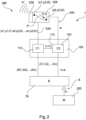
- Figure 1 shows schematically a holding arm 1, only partially shown, with a connected mechatronic assistance system 200, wherein the assistance system 200 is coupled to a bus system 76 of the holding arm 1 via an assistance interface 8 of the holding arm 1.
- the holding arm 1 has an assistance operating device 280 with a touch-sensitive sensor field designed contact means 238, wherein the touch-sensitive sensor field represents an alternative to the control ring according to the invention.
- the contact means 238 of the assistance operating device 280 designed as a touch-sensitive sensor field supplies movement coordinates x1, y1; x2, y2; xn, yn on a touch-sensitive surface (not shown) and the respective detection time t1; t2; tn to a serial interface 240 (cf. Fig. 7 )
- the one assistance operating device 280 has an associated processing unit 100, which in the present example has a first microcontroller 110 and a second microcontroller 120.
- the two microcontrollers 110, 120 do not necessarily have to be present as discrete components, but can also be implemented by one and the same component.
- the two microcontrollers 110, 120 are provided as discrete components that are communicatively coupled via a data connection 115.
- the first microcontroller 110 of the processing unit 100 of the holding arm 1 receives the movement coordinates x1, y1; x2, y2; xn, yn and converts two consecutive coordinates x1, y1; x2, y2 into an internal data structure (three-dimensional movement vector). This determines the direction of movement r of the movement path P that the operator follows on the contact means 238 designed as a touch-sensitive sensor field. If only one finger is moved over the contact means 238 designed as a touch-sensitive sensor field, this is a two-dimensional movement, and the third coordinate in the movement vector r is accordingly 0.
- the first microcontroller 110 calculates a movement speed v from the two detection times t1; t2. This is transmitted together with the movement vector r to the second microcontroller 120. If an operator moves two fingers simultaneously on the contact means 238 designed as a touch-sensitive sensor field, two coordinates and detection times are transmitted simultaneously. For three fingers, the corresponding three.
- the motion vector r (0, 0, -1), converted into a request signal m, would, if transmitted to the mechatronic assistance system 200 as required, cause the linear module to extend.
- the first microcontroller 110 of the processing unit 100 is communicatively coupled to an internal bus system 76, which is part of a transmission device that is arranged within the holding arm 1 and connects the assistance interface 8 to a base interface (not shown) of the holding arm 1 for transmitting signals between the interfaces.
- the first microcontroller 110 of the processing unit 100 is designed in the present case to read out sensor data (SI1, SI2, SIN) relating to the holding arm 1 via the bus system 76. From this sensor data (SI1, SI2, SIN), the first microcontroller 110 of the processing unit 100 calculates the position of the holding arm in space in order to determine the position of the contact means 238 and to include this in the calculation of the (resulting) motion vector r.
- the resulting motion vector is calculated in such a way that a transformation matrix is calculated which represents the current position of the contact means 238 in space relative to a base coordinate system of the holding arm 1 and preferably has at least one rotational and one translational transformation component; and/or that a transition matrix is calculated which represents the current position of the contact means 238 in space Space relative to an operating point of the mechatronic assistance system 200; and/or that the motion vector r of the contact means determined by the first microcontroller 110 is multiplied from the right by the transition matrix, which in turn is multiplied from the right by the transformation matrix.
- the motion vector r and the motion speed v form a data structure that is transmitted from the first microcontroller 110 to the second microcontroller 120 via the data connection 115.
- the second microcontroller 120 of the processing unit 100 is also communicatively coupled to the internal bus system 76 and is designed to query the internal bus system 76 as to whether there are workspace restrictions (CI, C2, ..Cn) in a planning file or, for example, in an intraoperative navigation system. Furthermore, the second microcontroller 120 is designed to transmit a request signal m to the assistance interface 8 as needed for the purpose of controlling the surgical mechatronic assistance system 200.
- the request signal m representing the operating action is forwarded to the assistance interface 8 and converted by the surgical mechatronic assistance system 200 into a control signal for controlling internal motors.
- the second microcontroller 120 of the processing unit 100 determines that the surgical mechatronic assistance system 200 would leave the permissible working area if controlled according to the request signal m (e.g. "endoscope touches the target area in an undesirable manner")
- the second microcontroller 120 of the assistance operating device 280 issues a warning w, which is converted in the signaling means 239 of the processing unit 100 into a warning signal perceptible to the operator, in this case, for example, a warning tone W'.
- a warning tone W' e.g. "endoscope touches the target area in an undesirable manner
- FIG 3 shows a holding arm 1 according to a second embodiment of the invention.
- the holding arm 1 is essentially identical to that shown in the Figures 1 and 2 and has seven arm segments 10, 12, 14, 16, 18, 20, 22.
- the arm operating device 280 of the holding arm 1 has a control ring 29. In the present case, this is arranged around the penultimate arm segment 20 and - as indicated by the arrows - can be rotated at least circumferentially around the arm segment 20 about the longitudinal axis L of the arm segment 20 or can be moved axially along the longitudinal axis L.
- a corresponding request signal which can have or represent the direction of rotation, the angle of rotation, the rotation speed and/or the rotation acceleration, is transmitted via the internal bus system 76 (cf. Fig. 2 ) to the surgical mechatronic assistance system 200.
- the control software of the assistance system 200 receives the request signal and calculates one or more control commands from it and sends these to the motors (not shown) of the assistance system 200.
- the processing unit 100 detects this and sends the direction of movement as well as the movement distance and the movement speed as well as the movement acceleration to the assistance system 200 via the internal bus system 76.
- FIG. 4 shows a holding arm 1 for medical purposes, in particular for holding a surgical mechatronic assistance system and/or surgical instrument (not shown) according to a third embodiment.
- the holding arm 1 has an assistance operating device 280 according to the invention, which is provided here as a group of buttons.
- an arm operating device 28 is provided, by means of which at least one joint, preferably each joint 11, 13, 15, 17, 19, 21, 23, can be released and locked so that the holding arm 1 can be brought into a desired pose.
- the arm operating device 28 is designed to contact an operator and one of the two or more arm segments (10, 12, 14, 16, 18, 20, 22) to release the associated joint (11, 13, 15, 17, 19, 21, 23). This is explained in more detail below.
- the holding arm 1 has a proximal end 2 and a distal end 4.
- a base interface 6 and a mechanical interface 7 are formed on the proximal end 2.
- the mechanical interface 7 is used to attach the holding arm 1 to a base, such as in particular to an operating table.
- the interface 7 is used to transfer energy and to couple the holding arm 1 to an external control unit (see. Fig. 6 ).
- a second interface 8 is provided at the distal end 4, via which a mechatronic assistance system and/or a surgical instrument, such as in particular a manipulator, can be coupled to the holding arm 1.
- a manipulator for holding and manipulating an endoscope is arranged here.
- the holding arm 1 has seven arm segments 10, 12, 14, 16, 18, 20, 22, each of which is essentially rod-shaped and, with the exception of the last arm segment 22, all of which are essentially the same length.
- the seven arm segments 10, 12, 14, 16, 18, 20, 22 are each coupled to one another by joints 11, 13, 15, 17, 19, 21, 23, with the zeroth joint 11 connecting the holding arm 1 to the base (in Fig. 4 not shown, see Fig. 1 ) is coupled.
- the joints 13, 15, 17, 19, 21, 23 are all designed as rotary joints with one degree of freedom each, according to this embodiment.
- the zeroth joint 11 is assigned to the zeroth segment 10
- the first joint 13 is assigned to the first arm segment 12
- the second joint 15 is assigned to the second arm segment 14
- the third joint 17 is assigned to the third arm segment 16
- the fourth joint 19 is assigned to the fourth arm joint 18
- the fifth joint 21 is assigned to the fifth arm segment 20
- the sixth joint 23 is assigned to the sixth arm segment 22.
- the joint 11 is designed as a translatory joint, so that the arm segment 10 can be extended telescopically in order to adjust the height of the holding arm 1, as will be explained later with reference to Figure 8 will be explained.
- the joints 13, 15, 17, 19, 21, 23 each have pivot axes A 1 , A 2 , A 3 , A 4 , A 5 , A 6 , whereby adjacent joints each have pivot axes that are perpendicular to one another. This enables the distal end 4 to be easily positioned in space.
- the holding arm 1 further comprises an arm operating device 28.
- the holding arm 1 can be brought into a desired pose by means of the arm operating device 28, wherein the arm operating device 28 is designed to release the associated joint upon contact between an operator and one of the seven arm segments.
- the arm operating device 28 according to this embodiment comprises seven contact sections 30, 32, 34, 36, 38, 40, 42, wherein a contact means 30, 32, 34, 36, 38, 40, 42 is arranged on each arm segment 10, 12, 14, 16, 18, 20, 22.
- a zeroth contact means 30 is arranged on the zeroth arm segment 10, a first contact means 32 on the first arm segment 12, a second contact means 34 on the second arm segment 14, a third contact means 36 on the third arm segment 16, a fourth contact means 38 on the fourth arm segment 18, a fifth contact means 40 on the fifth arm segment 20 and a sixth contact means 42 on the sixth arm segment 22.
- each contact means 30, 32, 34, 36, 38, 40, 42 has two contact means elements 30a, 30b, 32a, 32b, 34a, 34b, 36a, 36b, 38a, 38b, 40a, 40b, 42a, 42b arranged essentially opposite one another.
- the contact means 30, 32, 34, 36, 38, 40, 42 serve to detect contact of an operator with the corresponding arm segment 10, 12, 14, 16, 18, 20, 22.
- the operator comes into contact with both contact means elements 30a, 30b to 42a, 42b, and only when contact is made with both contact means elements 30a, 30b to 42a, 42b of a contact means 30 to 42 is the associated joint released.
- the second contact means 34 has two contact means elements 34a, 34b, which are provided essentially opposite each other on the circumference of the arm segment 14.
- this contact is detected by the arm operating device 28 and the joint 15 assigned to the arm segment 14 is released.
- pivoting about the axis A 2 is possible, so that the distal end 4, in relation to Figure 4 , can be swivelled up or down.
- all other joints 13, 17, 19, 21, 23 remain locked so that no movement takes place in them.
- the arm operating device 28 can have a controller or microprocessor which is designed to detect a contact between contact elements 30a, 30b to 42a, 42b and to convert it into electrical signals.
- the contact means 30 or the contact means elements 30a, 30b to 42a, 42b are designed as touch-sensitive sensors and detect a pressure of a contact between the operator and the corresponding contact means element 30a, 30b to 42a, 42b.
- the contact means elements 30a, 30b to 42a, 42b are preferably designed as capacitive touch-sensitive sensors.
- the holding arm when two arm segments come into contact at the same time, according to this example the arm segments 14 and 18, not the joints 15 and 19 are released, but all the joints between these arm segments 14 and 18, i.e. according to this embodiment the joints 17 and 19.
- the joint 15 remains locked.
- the holding arm 1 can now be changed in its pose so that rotation about the axis A3 and the axis A4 is possible. This is a particularly intuitive operation of the holding arm. Accordingly, for example when there is contact between the operator and the holding arm segments 12 and 20, the joints 15, 17, 19 and 21 are released.
- the holding arm 1 has a weight compensation device 50.
- the weight compensation device 50 has a gas pressure spring element which is coupled to the arm segment 14 and the arm segment 12.
- the weight compensation device can also have a cable pull and/or a balanced counterweight.
- the greatest moment rests on the joint 15 about its axis of rotation A2. Consequently, it is preferable to support precisely this joint 15 by means of the weight compensation device 50.
- Figure 5 in the holding arm 1 in addition to the already in Figure 4 The elements shown are the brakes 60, 62, 64, 66, 68, 70, 72, by means of which the joints 11, 13, 15, 17, 19, 21, 23 can be released and locked.
- the same and similar elements are given the same reference numerals as in Figure 4 and in this respect reference is made in full to the above description.
- the reference numerals on the contact means elements of the contact means 30, 32, 34, 36, 38, 40, 42 are not shown for reasons of clarity, they are nevertheless present, as can be seen from a comparison of the Figures 4 and 5
- the holding arm 1 of the Figure 5 an arm control device 280 with a control ring 29.
- Each joint 11, 13, 15, 17, 19, 21, 23 is assigned a brake 60, 62, 64, 66, 68, 70, 72.
- the brake 60 is assigned to the joint 11, the brake 62 to the joint 13, the brake 64 to the joint 15, the brake 66 to the joint 17, the brake 68 to the joint 19, the brake 70 to the joint 21 and the brake 72 to the joint 23.
- All brakes 60 to 72 are designed as electromagnetic brakes with a permanent magnet such that they are pre-tensioned into a locked state when de-energized.
- the permanent magnet is designed such that it can lock the respective joint alone and the position of the holding arm 1 is maintained.
- An electronic control unit 74 is provided in the zeroth arm segment 10. This is connected via a bus system 76 (in Figure 5 only shown in arm segment 10; cf. Fig.
- a power line 78 is also provided, which can be coupled to an energy source via the interface 6 at the proximal end 2 of the holding arm 1.
- Figure 6 illustrates again the holding arm 1, which has already been described with reference to the Figures 4 and 5
- the holding arm 1 has a contactless assistance operating device 280 in the form of a camera with an integrated depth sensor.
- the holding arm 1 is shown integrated into a system.
- a surgical mechatronic assistance system 200 is arranged by means of the interface 8, which is coupled to the interface 8 via an interface 201.
- Both the surgical mechatronic assistance system 200 and the interface 201 are in Figure 6 only shown schematically.
- the assistance system 200 has a working section 202, which can be, for example, the tip of the endoscope.
- the holding arm 1 is according to Figure 6 about the mechanical Interface 7 is coupled to a base 204.
- the base 204 is also only shown schematically here. It can be designed, for example, as a standard rail of an operating table.
- the first interface 6 is coupled to an external control unit 206.
- the interface 6 is connected to the external control unit 206 by means of a cable 208.
- the external control unit 206 is designed as an operating system, which for example has a conventional computer and an input-output interface for operating the operating system.
- the operating system preferably has software components that are designed to store and process data that is transferred from the holding arm 1 to the interface 6.
- the interface 6 can also be provided that it communicates wirelessly with the operating system 206, for example via Bluetooth ® , Wi-Fi ® or similar.
- Figure 7 shows an embodiment of an arm segment, the fourth arm segment 18 being shown here. It should be recognized that the other arm segments 10, 12, 14, 16, 20, 22 can also be designed in the same way.
- the arm segment body 90 has a cavity 92 in which various elements, such as the brake 70, are arranged. Schematically shown in the Figures 4 and 5 are the joints 19, 21 and the two pivot axes A 4 , A 5 of the joints 19, 21, which each interact with the holding arm segment 18.
- the joint 19 is assigned to the holding arm segment 18.
- the arm segment body 90 has an outer surface 93 which is essentially cylindrical.
- the arm segment body 90 is made, for example, from a metal such as, in particular, aluminum or titanium, an alloy based on aluminum or titanium, or a fiber composite material such as GRP or CFRP, and is preferably designed in a lightweight construction.
- the arm segment 18 has according to Figure 7 an assistance control device 280 with a contact means designed as a touch-sensitive sensor field 238, which is coupled to the bus system 76 of the holding arm 1 via a data interface 240.
- a contact means designed as a touch-sensitive sensor field 238, which is coupled to the bus system 76 of the holding arm 1 via a data interface 240.
- the touch-sensitive sensor field represents an alternative to the control ring according to the invention.
- the arm segment 18 has according to Figure 7 a contact means 38 of the arm operating device, which is part of the arm operating device 28 (cf. Fig. 4 , 5 and 6 ).
- the contact means 38 has two contact means elements 38a, 38b, which are designed as touch-sensitive sensors and are arranged flush in the outer surface 93 of the arm segment 18.
- the two contact means elements 38a, 38b are arranged substantially opposite one another with respect to the axis A 5 , so that an operator comes into contact with both contact means elements 38a, 38b when gripping the arm segment 18, as described above.
- the two contact elements 38a, 38b are coupled to the bus system 76 by means of lines 94a, 94b.
- the contact elements 38a, 38b are coupled to the electronic control unit 74 via the bus system 76 and, via this, in turn to the brake 70, so that the brake 70 is released by the arm operating device 28 when an operator comes into contact with the contact elements 38a, 38b.
- an energy transmission system 78 as well as a cable channel 80 and a working channel 82 are arranged within the arm segment body 90.
- the contact elements 38a, 38b and the brake 70 are connected to an energy supply by means of the energy transmission system 78.
- an electronic module 96 is arranged in each arm segment, which is coupled to the bus system 76 via a line 96a.
- the contact elements 38a, 38b which are connected to the data bus system 76 via the line 94a, 94b, only interact with the electronic module 96, which converts the contact detected by the contact elements 38a, 38b into an actuating signal for the brake 70 and sends this actuating signal to the brake 70 via the bus system 76 to release the joint 19.
- an electronic module 96 is arranged in each arm segment, arranged, a substantially modular construction of the holding arm 1 is realized, and the individual arm segments 10 to 22 are independent of the electronic control unit 74, which is arranged in the proximal arm segment 10.
- the cable channel 80 serves to guide cables that run from the proximal end 2 to the distal end 4, in particular to supply the interface 8.
- the working channel 82 serves to accommodate hoses or light guides and the like that are required depending on the type of manipulator that is arranged at the interface 8. If, for example, an endoscope is arranged at the interface 8, a light guide that can transmit an image that an endoscope camera records is preferably guided through the working channel 82.
- the working channel 82 therefore serves to accommodate appropriate transmission means depending on the area of application.
- a sensor 98 is arranged in the arm segment 18.
- a sensor is arranged in each arm segment 10 to 22, and it should be understood that the sensors in the arm segments 10, 12, 14, 16, 20 and 22 can be designed in the same way as the sensor 98 in the arm segment 18.
- the sensor 98 is preferably designed as an acceleration sensor. By providing such an acceleration sensor in each arm segment, it is possible to determine the pose of the holding arm 1 at any time.
- the sensor 98 is coupled to the data bus system 76 via a line 98a, so that the data recorded by the sensor 98 is transmitted to the electronic control unit 74, which then determines the pose of the holding arm 1 from all the sensor data from all the arm segments.
- the absolute and relative position of an end effector or manipulator arranged at the interface 8 can also be determined. It is also possible, if the holding arm 1 is arranged on an operating table, to detect a movement of this operating table. If all sensors in all arm segments detect a movement in the same direction, this is an indicator that the entire holding arm 1 has been moved while maintaining its pose, for example by the operating table or an operating table top being rotated or moved relative to a column of the operating table. Such a movement can also be detected by means of the sensors 98 Furthermore, external impulses, such as impacts on the holding arm 1, can be detected.
- a processing unit 100 associated with the assistance operating device 280 is provided in the arm segment 18 and is coupled to the data bus system 76 via the line 100a.
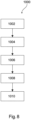
- Figure 8 shows a method 1000 according to the invention for controlling a surgical mechatronic assistance system coupled to a holding arm for medical purposes (see Figures 1 to 6 ).
- a first step 1002 an operating action of an operator aimed at controlling the assistance system is detected by means of an operating device arranged on the support arm.
- a reading 1004 of sensor data and workspace data relating to the holding arm takes place via the transmission device.
- a third step 1006 which serves for understanding, the recorded operating action is converted into a data structure taking into account the sensor data relating to the holding arm and the request signal is generated from the data structure.
- a fifth step 1010 which serves for understanding, the request signal representing the operating action is transmitted to the assistance interface for the purpose of controlling the surgical mechatronic assistance system.
- the method is preferably carried out with a holding arm 1 according to one of the above-described preferred embodiments of the holding arm 1 ( Fig. 1 to 7 ) is carried out.
Landscapes
- Health & Medical Sciences (AREA)
- Life Sciences & Earth Sciences (AREA)
- Surgery (AREA)
- Nuclear Medicine, Radiotherapy & Molecular Imaging (AREA)
- Molecular Biology (AREA)
- Public Health (AREA)
- Engineering & Computer Science (AREA)
- Biomedical Technology (AREA)
- Heart & Thoracic Surgery (AREA)
- Medical Informatics (AREA)
- Veterinary Medicine (AREA)
- Animal Behavior & Ethology (AREA)
- General Health & Medical Sciences (AREA)
- Pathology (AREA)
- Oral & Maxillofacial Surgery (AREA)
- Radiology & Medical Imaging (AREA)
- Gynecology & Obstetrics (AREA)
- Physics & Mathematics (AREA)
- Biophysics (AREA)
- Optics & Photonics (AREA)
- Manipulator (AREA)
Claims (7)
- Bras de maintien (1) à usage médical, en particulier pour le maintien d'un système d'assistance mécatronique (200), avec- une extrémité proximale (2) pour fixer le bras de maintien (1) à une base (204) et une extrémité distale (4) pour recevoir le système d'assistance mécatronique chirurgical (200);- une interface de base (6) à l'extrémité proximale (2) pour connecter le bras de maintien (1) à une unité de commande externe (206) pour transmettre des signaux vers et depuis le bras de maintien (1);- une interface d'assistance (8) à l'extrémité distale (4) pour coupler le bras de maintien (1) au système d'assistance (200) pour commander le système d'assistance (200);- un dispositif de transmission (76, 78), lequel est disposé à l'intérieur du bras de maintien (1) et connecte l'interface d'assistance (6) à l'interface de base (8) pour la transmission de signaux entre les interfaces (6, 8);- un dispositif de commande d'assistance (280), qui est configuré pour détecter une action de commande d'un opérateur dirigée pour commander le système d'assistance (200) et, si nécessaire, pour provoquer une transmission d'un signal de demande (m) représentant l'action de commande à l'interface d'assistance (8) afin de commander le système d'assistance mécatronique chirurgical (200); et- une unité de traitement (100) associée au dispositif de commande d'assistance (280), qui est configurée pour convertir l'action de commande en une structure de données, dans lequel la structure de données comprend un vecteur de mouvement 3D (r) et une valeur de vitesse (v),caractérisé en ce que le dispositif de commande d'assistance (280) présente au moins une bague de commande (29) qui est disposée de manière mobile sur le pourtour et/ou axialement autour d'au moins un segment de bras (20), dans lequel lorsqu'un opérateur fait tourner la bague de commande (29) autour d'un axe longitudinal (L), ceci est détecté par l'unité de traitement (100) et un signal de demande correspondant, qui peut représenter une direction de rotation, un angle de rotation, une vitesse de rotation et/ou une accélération de rotation, est envoyé au système d'assistance mécatronique chirurgical (200) par l'intermédiaire du dispositif de transmission (76).
- Bras de maintien selon la revendication 1, dans lequel l'unité de traitement (100) est au moins temporairement couplée au dispositif de transmission et est configurée pour lire des données de capteur (SI1, SI2, SIN) et/ou des données d'espace de travail concernant le bras de maintien (1) à partir du dispositif de transmission.
- Bras de maintien selon la revendication 2, dans lequel l'unité de traitement (100) est configurée pour prendre en compte les données de capteur (SI1, SI2, SIN) concernant le bras de maintien lors de la conversion de l'action de commande dans la structure de données.
- Bras de maintien selon l'une quelconque des revendications précédentes, dans lequel l'unité de traitement (100) est configurée pour convertir la structure de données en signal de demande.
- Bras de maintien selon l'une quelconque des revendications précédentes, dans lequel l'unité de traitement (100) est configurée pour déterminer si le système d'assistance mécatronique chirurgical (200) resterait dans un espace de travail admissible en cas de commande selon le signal de demande, et dans lequel l'unité de traitement (100) est configurée pour provoquer une transmission du signal de demande au système d'assistance mécatronique chirurgical (200) uniquement si le système d'assistance mécatronique chirurgical (200) reste dans un espace de travail admissible en cas de commande selon le signal de demande.
- Bras de maintien selon l'une quelconque des revendications précédentes, avec deux ou plusieurs segments de bras (10, 12, 14, 16, 18, 20, 22) et deux ou plusieurs articulations (11, 13, 15, 17, 19, 21, 23), au moyen desquels les segments de bras (10, 12, 14, 16, 18, 20, 22) sont connectés de manière articulée, dans lequel un dispositif de commande de bras (28) est prévu en plus du dispositif de commande d'assistance (280), au moyen duquel au moins une articulation, de préférence chaque articulation (11, 13, 15, 17, 19, 21, 23), peut être libérée et bloquée, de sorte que le bras de maintien peut être amené dans une position souhaitée, dans lequel le dispositif de commande de bras (28) est de préférence configuré pour libérer l'articulation associée (11, 13, 15, 17, 19, 21, 23) en cas de contact entre un opérateur et un des deux ou plusieurs segments de bras (10, 12, 14, 16, 18, 20, 22).
- Procédé (1000) de commande d'un système d'assistance mécatronique chirurgical couplé à un bras de maintien à usage médical selon l'une quelconque des revendications précédentes avec les étapes consistant à :- détecter (1002) une action de commande d'un opérateur dirigée pour commander le système d'assistance au moyen du dispositif de commande d'assistance (280) disposé sur le bras de maintien (1), qui présente l'au moins une bague de commande (29), qui est disposée de manière mobile sur le pourtour et/ou axialement autour d'au moins un segment de bras (20);- transmettre, au besoin (1010), un signal de demande représentant l'action de commande, qui peut représenter une direction de rotation, un angle de rotation, une vitesse de rotation et/ou une accélération de rotation, à l'interface d'assistance (8) afin de commander le système d'assistance mécatronique chirurgical;- convertir l'action de commande détectée en une structure de données, dans lequel la structure de données comprend de préférence un vecteur de mouvement 3D et une valeur de vitesse; et- générer le signal de demande à partir de la structure de données.
Applications Claiming Priority (2)
| Application Number | Priority Date | Filing Date | Title |
|---|---|---|---|
| DE102015104810.8A DE102015104810A1 (de) | 2015-03-27 | 2015-03-27 | Verfahren und Vorrichtung zum Steuern eines chirurgischen mechatronischen Assistenzsystems mittels eines Haltearms für medizinische Zwecke |
| PCT/EP2016/056459 WO2016156168A1 (fr) | 2015-03-27 | 2016-03-23 | Procédé et dispositif pour assurer la commande d'un système d'assistance mécatronique chirurgical au moyen d'un bras de retenue à usage médical |
Publications (2)
| Publication Number | Publication Date |
|---|---|
| EP3273897A1 EP3273897A1 (fr) | 2018-01-31 |
| EP3273897B1 true EP3273897B1 (fr) | 2024-10-16 |
Family
ID=55629025
Family Applications (1)
| Application Number | Title | Priority Date | Filing Date |
|---|---|---|---|
| EP16711825.6A Active EP3273897B1 (fr) | 2015-03-27 | 2016-03-23 | Procédé et dispositif pour assurer la commande d'un système d'assistance mécatronique chirurgical au moyen d'un bras de retenue à usage médical |
Country Status (5)
| Country | Link |
|---|---|
| US (1) | US10993777B2 (fr) |
| EP (1) | EP3273897B1 (fr) |
| CA (1) | CA2980964C (fr) |
| DE (1) | DE102015104810A1 (fr) |
| WO (1) | WO2016156168A1 (fr) |
Families Citing this family (31)
| Publication number | Priority date | Publication date | Assignee | Title |
|---|---|---|---|---|
| US10368878B2 (en) | 2013-06-11 | 2019-08-06 | Orthotaxy | System for positioning a surgical device |
| WO2016160272A1 (fr) | 2015-03-27 | 2016-10-06 | Sonitrack Systems, Inc. | Bras de support alimenté rapidement repositionnable |
| US11395709B2 (en) * | 2017-02-28 | 2022-07-26 | Sony Corporation | Control system, control method, and surgical arm system |
| DE102017111296B3 (de) | 2017-05-23 | 2018-08-02 | Medineering Gmbh | Robotischer Manipulator zur Führung eines Endoskops mit Parallelkinematik |
| DE102017111289B3 (de) | 2017-05-23 | 2018-08-23 | Medineering Gmbh | Passiver chirurgischer Manipulator mit handgehaltener Antriebseinheit |
| DE102017111302A1 (de) | 2017-05-23 | 2018-11-29 | Medineering Gmbh | Medizinische mechatronische männliche sowie weibliche Schnittstelleneinrichtung |
| US10987175B2 (en) | 2017-12-06 | 2021-04-27 | Medtech S.A. | Robotic shoulder repair and reconstruction |
| US10687792B2 (en) | 2018-03-12 | 2020-06-23 | Zimmer Biomet CMF and Thoracic, LLC | End effector coupler for surgical arm |
| US10772704B2 (en) | 2018-03-12 | 2020-09-15 | Zimmer Biomet CMF and Thoracic, LLC | End effector coupler for surgical arm |
| USD878585S1 (en) | 2018-03-12 | 2020-03-17 | Zimmer Biomet CMF and Thoracic, LLC | End effector coupler stem |
| US10835345B2 (en) | 2018-03-12 | 2020-11-17 | Zimmer Biomet CMF and Thoracic, LLC | End effector coupler for surgical arm |
| WO2019177569A1 (fr) * | 2018-03-12 | 2019-09-19 | Zimmer Biomet CMF and Thoracic, LLC | Dispositif d'accouplement d'effecteur terminal pour bras chirurgical |
| CN109316235B (zh) * | 2018-10-10 | 2021-04-30 | 江西欧德医疗器材有限公司 | 一种智能骨针操控系统及使用方法 |
| CN113286548A (zh) | 2018-12-21 | 2021-08-20 | 史密夫和内修有限公司 | 具有张力反馈的致动牵开器 |
| US20220110685A1 (en) | 2019-02-05 | 2022-04-14 | Smith & Nephew, Inc. | Methods for improving robotic surgical systems and devices thereof |
| USD982746S1 (en) * | 2019-02-13 | 2023-04-04 | Curexo, Inc. | Medical device holder |
| JP2020162994A (ja) * | 2019-03-29 | 2020-10-08 | リバーフィールド株式会社 | 操作部およびアーム装置 |
| WO2020206216A1 (fr) | 2019-04-05 | 2020-10-08 | Smith & Nephew, Inc. | Procédés et système de fabrication d'un implant d'articulation |
| US11272989B2 (en) | 2019-04-29 | 2022-03-15 | Smith & Nephew, Inc. | Multi-level positional tracking |
| US11389304B1 (en) | 2019-05-06 | 2022-07-19 | Smith & Nephew, Inc. | Devices, systems and methods for providing instrument orientation feedback |
| US12144551B1 (en) | 2019-06-26 | 2024-11-19 | Smith & Nephew, Inc. | Computer-assisted tissue navigation |
| US12127791B1 (en) | 2019-07-08 | 2024-10-29 | Smith & Nephew, Inc. | Simulation-enhanced intraoperative surgical planning tool for robotics-assisted total knee arthroplasty |
| DE102019121360A1 (de) * | 2019-08-07 | 2021-02-11 | Karl Storz Se & Co. Kg | Vorrichtung zur simultanen Fixierung von medizinischen Instrumenten und entsprechendes System |
| CN114466625B (zh) | 2019-10-03 | 2026-04-10 | 史密夫和内修有限公司 | 全膝关节置换翻修术期间的髓内管的配准 |
| US11517334B1 (en) | 2019-11-04 | 2022-12-06 | Smith & Nephew, Inc. | Patient-specific guides for latarjet procedure |
| US12533805B2 (en) | 2020-10-30 | 2026-01-27 | Mako Surgical Corp. | Robotic surgical system with cut selection logic |
| US12527632B2 (en) | 2020-12-15 | 2026-01-20 | Mako Surgical Corp. | Systems and methods for initial assessment warnings |
| USD1044829S1 (en) | 2021-07-29 | 2024-10-01 | Mako Surgical Corp. | Display screen or portion thereof with graphical user interface |
| WO2023059589A1 (fr) | 2021-10-05 | 2023-04-13 | Smith & Nephew, Inc. | Systèmes de guide de coupe |
| WO2023064433A1 (fr) | 2021-10-13 | 2023-04-20 | Smith & Nephew, Inc. | Procédés d'alignement et de suivi chirurgical à l'aide de dispositifs d'imagerie hybrides et systèmes associés |
| WO2026080426A1 (fr) | 2024-10-10 | 2026-04-16 | Smith & Nephew, Inc. | Interface utilisateur de cartographie colorimétrique dynamique de contact implant-os lors de la pose peropératoire d'implant |
Citations (1)
| Publication number | Priority date | Publication date | Assignee | Title |
|---|---|---|---|---|
| WO2014151550A2 (fr) * | 2013-03-15 | 2014-09-25 | Stryker Corporation | Manipulateur chirurgical apte à commander un instrument chirurgical dans de multiples modes |
Family Cites Families (19)
| Publication number | Priority date | Publication date | Assignee | Title |
|---|---|---|---|---|
| US6400352B1 (en) * | 1995-01-18 | 2002-06-04 | Immersion Corporation | Mechanical and force transmission for force feedback devices |
| EP1029418A2 (fr) * | 1997-11-07 | 2000-08-23 | Hill-Rom, Inc. | Dispositif de communication et d'entree de donnees |
| US6569084B1 (en) * | 1999-03-31 | 2003-05-27 | Olympus Optical Co., Ltd. | Endoscope holder and endoscope device |
| ATE394719T1 (de) * | 2001-01-29 | 2008-05-15 | Acrobot Company Ltd | Roboter mit aktiven beschränkungen |
| US7747311B2 (en) * | 2002-03-06 | 2010-06-29 | Mako Surgical Corp. | System and method for interactive haptic positioning of a medical device |
| JP2005013715A (ja) * | 2003-06-05 | 2005-01-20 | Olympus Corp | 観察システム |
| JP4559093B2 (ja) * | 2003-10-03 | 2010-10-06 | オリンパス株式会社 | 医療用具支持装置 |
| US8337407B2 (en) * | 2003-12-30 | 2012-12-25 | Liposonix, Inc. | Articulating arm for medical procedures |
| JP4472365B2 (ja) * | 2004-01-23 | 2010-06-02 | オリンパス株式会社 | 医療器具保持装置 |
| DE202004002907U1 (de) | 2004-02-25 | 2004-05-06 | Gebr. Bode Gmbh & Co. Kg | Schiebetür oder Schwenkschiebetür für Fahrzeuge des öffentlichen Personennah- und -fernverkehrs |
| US20050209614A1 (en) | 2004-03-04 | 2005-09-22 | Fenter Felix W | Anastomosis apparatus and methods with computer-aided, automated features |
| US8160743B2 (en) | 2005-08-16 | 2012-04-17 | Brainlab Ag | Anthropomorphic medical robot arm with movement restrictions |
| ES2298051B2 (es) * | 2006-07-28 | 2009-03-16 | Universidad De Malaga | Sistema robotico de asistencia a la cirugia minimamente invasiva capaz de posicionar un instrumento quirurgico en respueta a las ordenes de un cirujano sin fijacion a la mesa de operaciones ni calibracion previa del punto de insercion. |
| US9542001B2 (en) * | 2010-01-14 | 2017-01-10 | Brainlab Ag | Controlling a surgical navigation system |
| CN104703541A (zh) * | 2012-10-08 | 2015-06-10 | 皇家飞利浦有限公司 | 医学x射线成像系统的紧急激活 |
| DE102012110190B4 (de) * | 2012-10-25 | 2015-03-26 | Mis-Robotics Gmbh | Manuell betätigte Robotersteuerung und Verfahren zum Steuern eines Robotersystems |
| EP2951743B1 (fr) * | 2013-02-04 | 2020-04-29 | Children's National Medical Center | Système chirurgical robotisé à commande hybride |
| EP2923669B1 (fr) * | 2014-03-24 | 2017-06-28 | Hansen Medical, Inc. | Systèmes et dispositifs pour le guidage instinctif d'un cathéter |
| DE102014016823B4 (de) | 2014-11-14 | 2017-06-29 | Medineering Gmbh | Verfahren zum Steuern eines an einem Haltearm gekoppelten mechatronischen Assistenzsystems |
-
2015
- 2015-03-27 DE DE102015104810.8A patent/DE102015104810A1/de active Pending
-
2016
- 2016-03-23 WO PCT/EP2016/056459 patent/WO2016156168A1/fr not_active Ceased
- 2016-03-23 US US15/561,042 patent/US10993777B2/en active Active
- 2016-03-23 EP EP16711825.6A patent/EP3273897B1/fr active Active
- 2016-03-23 CA CA2980964A patent/CA2980964C/fr active Active
Patent Citations (1)
| Publication number | Priority date | Publication date | Assignee | Title |
|---|---|---|---|---|
| WO2014151550A2 (fr) * | 2013-03-15 | 2014-09-25 | Stryker Corporation | Manipulateur chirurgical apte à commander un instrument chirurgical dans de multiples modes |
Also Published As
| Publication number | Publication date |
|---|---|
| US20180071049A1 (en) | 2018-03-15 |
| WO2016156168A1 (fr) | 2016-10-06 |
| EP3273897A1 (fr) | 2018-01-31 |
| CA2980964C (fr) | 2023-05-02 |
| DE102015104810A1 (de) | 2016-09-29 |
| CA2980964A1 (fr) | 2016-10-06 |
| US10993777B2 (en) | 2021-05-04 |
Similar Documents
| Publication | Publication Date | Title |
|---|---|---|
| EP3273897B1 (fr) | Procédé et dispositif pour assurer la commande d'un système d'assistance mécatronique chirurgical au moyen d'un bras de retenue à usage médical | |
| EP3217909B1 (fr) | Bras de support intelligent pour chirurgie de la tête avec commandes sensibles au contact | |
| DE102014016823B4 (de) | Verfahren zum Steuern eines an einem Haltearm gekoppelten mechatronischen Assistenzsystems | |
| DE102013110847B3 (de) | Steuervorrichtung und Verfahren zum Steuern eines Robotersystems mittels Gestensteuerung | |
| DE102012110190B4 (de) | Manuell betätigte Robotersteuerung und Verfahren zum Steuern eines Robotersystems | |
| DE102015200428B3 (de) | Verfahren zur Ausrichtung eines mehrachsigen Manipulators mit einem Eingabegerät | |
| EP2449997B1 (fr) | Poste de travail médical | |
| DE102014016824B4 (de) | Intelligenter Haltearm für die Kopfchirurgie mit berührungsempfindlicher Bedienung | |
| DE102015104819B4 (de) | Haltearm für medizinische Zwecke mit abnehmbarer Bedieneinrichtung, sowie Bedieneinrichtung hierfür | |
| DE102013108114B4 (de) | Eingabevorrichtung zur Gestensteuerung mit Schutzeinrichtung | |
| DE102013100605A1 (de) | Robotersystem und Verfahren zum Steuern eines Robotersystems für die minimal invasive Chirurgie | |
| EP3233393B1 (fr) | Procédé permettant de coupler et de découpler de manière fiable un appareil d'entrée de données | |
| DE102019201277A1 (de) | Vorrichtung zur Führung eines medizinischen flexiblen Schafts | |
| EP3247303A1 (fr) | Système de téléopération à retour de force haptique intrinsèque par adaptation dynamique des caractéristiques de la force de préhension et des coordonnées de l'effecteur terminal | |
| US20220313349A1 (en) | System and method of dithering to maintain grasp force | |
| EP3273898B1 (fr) | Instrument chirurgical et système | |
| DE102014019752B4 (de) | Haltearm für medizinische Zwecke mit zwei mechatronischen Schnittstellen | |
| DE102014006264A1 (de) | Verfahren und Vorrichtung zum Steuern der Bewegung eines Objekts | |
| DE102018104714A1 (de) | Telemanipulatorsystem und Verfahren zum Betreiben eines Telemanipulatorsystems | |
| EP4432957A1 (fr) | Robot médical à commande intuitive, et procédé de commande | |
| DE102016117751B4 (de) | Medizinischer Haltearm mit mechatronischer Schnittstelle und System aus dem Haltearm und einem Assistenzsystem | |
| DE112022002158B4 (de) | Kontrollierter widerstand in rückfahrbaren gelenken | |
| DE102023129470A1 (de) | Medizinischer Joystick mit Freigabesensor, medizinisches System und computerimplementiertes Steuerverfahren |
Legal Events
| Date | Code | Title | Description |
|---|---|---|---|
| STAA | Information on the status of an ep patent application or granted ep patent |
Free format text: STATUS: THE INTERNATIONAL PUBLICATION HAS BEEN MADE |
|
| PUAI | Public reference made under article 153(3) epc to a published international application that has entered the european phase |
Free format text: ORIGINAL CODE: 0009012 |
|
| STAA | Information on the status of an ep patent application or granted ep patent |
Free format text: STATUS: REQUEST FOR EXAMINATION WAS MADE |
|
| 17P | Request for examination filed |
Effective date: 20171027 |
|
| AK | Designated contracting states |
Kind code of ref document: A1 Designated state(s): AL AT BE BG CH CY CZ DE DK EE ES FI FR GB GR HR HU IE IS IT LI LT LU LV MC MK MT NL NO PL PT RO RS SE SI SK SM TR |
|
| AX | Request for extension of the european patent |
Extension state: BA ME |
|
| DAV | Request for validation of the european patent (deleted) | ||
| DAX | Request for extension of the european patent (deleted) | ||
| STAA | Information on the status of an ep patent application or granted ep patent |
Free format text: STATUS: EXAMINATION IS IN PROGRESS |
|
| 17Q | First examination report despatched |
Effective date: 20200928 |
|
| RAP3 | Party data changed (applicant data changed or rights of an application transferred) |
Owner name: BRAINLAB ROBOTICS GMBH |
|
| GRAP | Despatch of communication of intention to grant a patent |
Free format text: ORIGINAL CODE: EPIDOSNIGR1 |
|
| STAA | Information on the status of an ep patent application or granted ep patent |
Free format text: STATUS: GRANT OF PATENT IS INTENDED |
|
| INTG | Intention to grant announced |
Effective date: 20240618 |
|
| GRAS | Grant fee paid |
Free format text: ORIGINAL CODE: EPIDOSNIGR3 |
|
| GRAA | (expected) grant |
Free format text: ORIGINAL CODE: 0009210 |
|
| STAA | Information on the status of an ep patent application or granted ep patent |
Free format text: STATUS: THE PATENT HAS BEEN GRANTED |
|
| AK | Designated contracting states |
Kind code of ref document: B1 Designated state(s): AL AT BE BG CH CY CZ DE DK EE ES FI FR GB GR HR HU IE IS IT LI LT LU LV MC MK MT NL NO PL PT RO RS SE SI SK SM TR |
|
| P01 | Opt-out of the competence of the unified patent court (upc) registered |
Free format text: CASE NUMBER: APP_51221/2024 Effective date: 20240910 |
|
| REG | Reference to a national code |
Ref country code: GB Ref legal event code: FG4D Free format text: NOT ENGLISH |
|
| REG | Reference to a national code |
Ref country code: CH Ref legal event code: EP |
|
| REG | Reference to a national code |
Ref country code: IE Ref legal event code: FG4D Free format text: LANGUAGE OF EP DOCUMENT: GERMAN |
|
| REG | Reference to a national code |
Ref country code: DE Ref legal event code: R096 Ref document number: 502016016751 Country of ref document: DE |
|
| REG | Reference to a national code |
Ref country code: LT Ref legal event code: MG9D |
|
| REG | Reference to a national code |
Ref country code: NL Ref legal event code: MP Effective date: 20241016 |
|
| PG25 | Lapsed in a contracting state [announced via postgrant information from national office to epo] |
Ref country code: NL Free format text: LAPSE BECAUSE OF FAILURE TO SUBMIT A TRANSLATION OF THE DESCRIPTION OR TO PAY THE FEE WITHIN THE PRESCRIBED TIME-LIMIT Effective date: 20241016 |
|
| PG25 | Lapsed in a contracting state [announced via postgrant information from national office to epo] |
Ref country code: NL Free format text: LAPSE BECAUSE OF FAILURE TO SUBMIT A TRANSLATION OF THE DESCRIPTION OR TO PAY THE FEE WITHIN THE PRESCRIBED TIME-LIMIT Effective date: 20241016 |
|
| PG25 | Lapsed in a contracting state [announced via postgrant information from national office to epo] |
Ref country code: HR Free format text: LAPSE BECAUSE OF FAILURE TO SUBMIT A TRANSLATION OF THE DESCRIPTION OR TO PAY THE FEE WITHIN THE PRESCRIBED TIME-LIMIT Effective date: 20241016 Ref country code: IS Free format text: LAPSE BECAUSE OF FAILURE TO SUBMIT A TRANSLATION OF THE DESCRIPTION OR TO PAY THE FEE WITHIN THE PRESCRIBED TIME-LIMIT Effective date: 20250216 Ref country code: PT Free format text: LAPSE BECAUSE OF FAILURE TO SUBMIT A TRANSLATION OF THE DESCRIPTION OR TO PAY THE FEE WITHIN THE PRESCRIBED TIME-LIMIT Effective date: 20250217 |
|
| PG25 | Lapsed in a contracting state [announced via postgrant information from national office to epo] |
Ref country code: FI Free format text: LAPSE BECAUSE OF FAILURE TO SUBMIT A TRANSLATION OF THE DESCRIPTION OR TO PAY THE FEE WITHIN THE PRESCRIBED TIME-LIMIT Effective date: 20241016 |
|
| PG25 | Lapsed in a contracting state [announced via postgrant information from national office to epo] |
Ref country code: BG Free format text: LAPSE BECAUSE OF FAILURE TO SUBMIT A TRANSLATION OF THE DESCRIPTION OR TO PAY THE FEE WITHIN THE PRESCRIBED TIME-LIMIT Effective date: 20241016 |
|
| PG25 | Lapsed in a contracting state [announced via postgrant information from national office to epo] |
Ref country code: ES Free format text: LAPSE BECAUSE OF FAILURE TO SUBMIT A TRANSLATION OF THE DESCRIPTION OR TO PAY THE FEE WITHIN THE PRESCRIBED TIME-LIMIT Effective date: 20241016 |
|
| PG25 | Lapsed in a contracting state [announced via postgrant information from national office to epo] |
Ref country code: NO Free format text: LAPSE BECAUSE OF FAILURE TO SUBMIT A TRANSLATION OF THE DESCRIPTION OR TO PAY THE FEE WITHIN THE PRESCRIBED TIME-LIMIT Effective date: 20250116 |
|
| PG25 | Lapsed in a contracting state [announced via postgrant information from national office to epo] |
Ref country code: LV Free format text: LAPSE BECAUSE OF FAILURE TO SUBMIT A TRANSLATION OF THE DESCRIPTION OR TO PAY THE FEE WITHIN THE PRESCRIBED TIME-LIMIT Effective date: 20241016 Ref country code: GR Free format text: LAPSE BECAUSE OF FAILURE TO SUBMIT A TRANSLATION OF THE DESCRIPTION OR TO PAY THE FEE WITHIN THE PRESCRIBED TIME-LIMIT Effective date: 20250117 |
|
| PG25 | Lapsed in a contracting state [announced via postgrant information from national office to epo] |
Ref country code: PL Free format text: LAPSE BECAUSE OF FAILURE TO SUBMIT A TRANSLATION OF THE DESCRIPTION OR TO PAY THE FEE WITHIN THE PRESCRIBED TIME-LIMIT Effective date: 20241016 |
|
| PG25 | Lapsed in a contracting state [announced via postgrant information from national office to epo] |
Ref country code: RS Free format text: LAPSE BECAUSE OF FAILURE TO SUBMIT A TRANSLATION OF THE DESCRIPTION OR TO PAY THE FEE WITHIN THE PRESCRIBED TIME-LIMIT Effective date: 20250116 |
|
| PG25 | Lapsed in a contracting state [announced via postgrant information from national office to epo] |
Ref country code: SM Free format text: LAPSE BECAUSE OF FAILURE TO SUBMIT A TRANSLATION OF THE DESCRIPTION OR TO PAY THE FEE WITHIN THE PRESCRIBED TIME-LIMIT Effective date: 20241016 |
|
| PGFP | Annual fee paid to national office [announced via postgrant information from national office to epo] |
Ref country code: DE Payment date: 20250409 Year of fee payment: 10 |
|
| PG25 | Lapsed in a contracting state [announced via postgrant information from national office to epo] |
Ref country code: DK Free format text: LAPSE BECAUSE OF FAILURE TO SUBMIT A TRANSLATION OF THE DESCRIPTION OR TO PAY THE FEE WITHIN THE PRESCRIBED TIME-LIMIT Effective date: 20241016 |
|
| REG | Reference to a national code |
Ref country code: DE Ref legal event code: R097 Ref document number: 502016016751 Country of ref document: DE |
|
| PG25 | Lapsed in a contracting state [announced via postgrant information from national office to epo] |
Ref country code: EE Free format text: LAPSE BECAUSE OF FAILURE TO SUBMIT A TRANSLATION OF THE DESCRIPTION OR TO PAY THE FEE WITHIN THE PRESCRIBED TIME-LIMIT Effective date: 20241016 |
|
| PG25 | Lapsed in a contracting state [announced via postgrant information from national office to epo] |
Ref country code: RO Free format text: LAPSE BECAUSE OF FAILURE TO SUBMIT A TRANSLATION OF THE DESCRIPTION OR TO PAY THE FEE WITHIN THE PRESCRIBED TIME-LIMIT Effective date: 20241016 |
|
| PG25 | Lapsed in a contracting state [announced via postgrant information from national office to epo] |
Ref country code: SK Free format text: LAPSE BECAUSE OF FAILURE TO SUBMIT A TRANSLATION OF THE DESCRIPTION OR TO PAY THE FEE WITHIN THE PRESCRIBED TIME-LIMIT Effective date: 20241016 |
|
| PG25 | Lapsed in a contracting state [announced via postgrant information from national office to epo] |
Ref country code: CZ Free format text: LAPSE BECAUSE OF FAILURE TO SUBMIT A TRANSLATION OF THE DESCRIPTION OR TO PAY THE FEE WITHIN THE PRESCRIBED TIME-LIMIT Effective date: 20241016 |
|
| PG25 | Lapsed in a contracting state [announced via postgrant information from national office to epo] |
Ref country code: IT Free format text: LAPSE BECAUSE OF FAILURE TO SUBMIT A TRANSLATION OF THE DESCRIPTION OR TO PAY THE FEE WITHIN THE PRESCRIBED TIME-LIMIT Effective date: 20241016 |
|
| PLBE | No opposition filed within time limit |
Free format text: ORIGINAL CODE: 0009261 |
|
| STAA | Information on the status of an ep patent application or granted ep patent |
Free format text: STATUS: NO OPPOSITION FILED WITHIN TIME LIMIT |
|
| PG25 | Lapsed in a contracting state [announced via postgrant information from national office to epo] |
Ref country code: SE Free format text: LAPSE BECAUSE OF FAILURE TO SUBMIT A TRANSLATION OF THE DESCRIPTION OR TO PAY THE FEE WITHIN THE PRESCRIBED TIME-LIMIT Effective date: 20241016 |
|
| 26N | No opposition filed |
Effective date: 20250717 |
|
| PG25 | Lapsed in a contracting state [announced via postgrant information from national office to epo] |
Ref country code: MC Free format text: LAPSE BECAUSE OF FAILURE TO SUBMIT A TRANSLATION OF THE DESCRIPTION OR TO PAY THE FEE WITHIN THE PRESCRIBED TIME-LIMIT Effective date: 20241016 |
|
| REG | Reference to a national code |
Ref country code: CH Ref legal event code: H13 Free format text: ST27 STATUS EVENT CODE: U-0-0-H10-H13 (AS PROVIDED BY THE NATIONAL OFFICE) Effective date: 20251023 |
|
| PG25 | Lapsed in a contracting state [announced via postgrant information from national office to epo] |
Ref country code: LU Free format text: LAPSE BECAUSE OF NON-PAYMENT OF DUE FEES Effective date: 20250323 |
|
| GBPC | Gb: european patent ceased through non-payment of renewal fee |
Effective date: 20250323 |
|
| REG | Reference to a national code |
Ref country code: BE Ref legal event code: MM Effective date: 20250331 |
|
| PG25 | Lapsed in a contracting state [announced via postgrant information from national office to epo] |
Ref country code: GB Free format text: LAPSE BECAUSE OF NON-PAYMENT OF DUE FEES Effective date: 20250323 |
|
| PG25 | Lapsed in a contracting state [announced via postgrant information from national office to epo] |
Ref country code: BE Free format text: LAPSE BECAUSE OF NON-PAYMENT OF DUE FEES Effective date: 20250331 |
|
| PG25 | Lapsed in a contracting state [announced via postgrant information from national office to epo] |
Ref country code: CH Free format text: LAPSE BECAUSE OF NON-PAYMENT OF DUE FEES Effective date: 20250331 |
|
| PG25 | Lapsed in a contracting state [announced via postgrant information from national office to epo] |
Ref country code: IE Free format text: LAPSE BECAUSE OF NON-PAYMENT OF DUE FEES Effective date: 20250323 |
|
| PGFP | Annual fee paid to national office [announced via postgrant information from national office to epo] |
Ref country code: FR Payment date: 20260324 Year of fee payment: 11 |