EP3218112B1 - Dispositifs modulaires de distribution de fluides - Google Patents
Dispositifs modulaires de distribution de fluides Download PDFInfo
- Publication number
- EP3218112B1 EP3218112B1 EP14905798.6A EP14905798A EP3218112B1 EP 3218112 B1 EP3218112 B1 EP 3218112B1 EP 14905798 A EP14905798 A EP 14905798A EP 3218112 B1 EP3218112 B1 EP 3218112B1
- Authority
- EP
- European Patent Office
- Prior art keywords
- reaction vessel
- reservoir
- reagent
- port
- wash buffer
- Prior art date
- Legal status (The legal status is an assumption and is not a legal conclusion. Google has not performed a legal analysis and makes no representation as to the accuracy of the status listed.)
- Active
Links
Images





Classifications
-
- B—PERFORMING OPERATIONS; TRANSPORTING
- B01—PHYSICAL OR CHEMICAL PROCESSES OR APPARATUS IN GENERAL
- B01L—CHEMICAL OR PHYSICAL LABORATORY APPARATUS FOR GENERAL USE
- B01L3/00—Containers or dishes for laboratory use, e.g. laboratory glassware; Droppers
- B01L3/02—Burettes; Pipettes
- B01L3/0289—Apparatus for withdrawing or distributing predetermined quantities of fluid
- B01L3/0293—Apparatus for withdrawing or distributing predetermined quantities of fluid for liquids
-
- B—PERFORMING OPERATIONS; TRANSPORTING
- B01—PHYSICAL OR CHEMICAL PROCESSES OR APPARATUS IN GENERAL
- B01F—MIXING, e.g. DISSOLVING, EMULSIFYING OR DISPERSING
- B01F31/00—Mixers with shaking, oscillating, or vibrating mechanisms
- B01F31/20—Mixing the contents of independent containers, e.g. test tubes
- B01F31/23—Mixing the contents of independent containers, e.g. test tubes by pivoting the containers about an axis
-
- B—PERFORMING OPERATIONS; TRANSPORTING
- B01—PHYSICAL OR CHEMICAL PROCESSES OR APPARATUS IN GENERAL
- B01L—CHEMICAL OR PHYSICAL LABORATORY APPARATUS FOR GENERAL USE
- B01L2300/00—Additional constructional details
- B01L2300/02—Identification, exchange or storage of information
- B01L2300/023—Sending and receiving of information, e.g. using Bluetooth®
-
- B—PERFORMING OPERATIONS; TRANSPORTING
- B01—PHYSICAL OR CHEMICAL PROCESSES OR APPARATUS IN GENERAL
- B01L—CHEMICAL OR PHYSICAL LABORATORY APPARATUS FOR GENERAL USE
- B01L2400/00—Moving or stopping fluids
- B01L2400/04—Moving fluids with specific forces or mechanical means
- B01L2400/0403—Moving fluids with specific forces or mechanical means specific forces
- B01L2400/0457—Moving fluids with specific forces or mechanical means specific forces passive flow or gravitation
-
- B—PERFORMING OPERATIONS; TRANSPORTING
- B01—PHYSICAL OR CHEMICAL PROCESSES OR APPARATUS IN GENERAL
- B01L—CHEMICAL OR PHYSICAL LABORATORY APPARATUS FOR GENERAL USE
- B01L2400/00—Moving or stopping fluids
- B01L2400/04—Moving fluids with specific forces or mechanical means
- B01L2400/0475—Moving fluids with specific forces or mechanical means specific mechanical means and fluid pressure
- B01L2400/0487—Moving fluids with specific forces or mechanical means specific mechanical means and fluid pressure fluid pressure, pneumatics
Definitions
- the present disclosure is directed, in part, to devices that deliver fluids from several reservoirs to a reaction vessel and eventually to a waste chamber in a predetermined schedule, and to methods of carrying out the same.
- This six step procedure is very time consuming and labor intensive.
- the operator has to return to the membrane once per hour in the reagent incubation steps and every 3 to 5 minutes in the wash steps, for a total of between 10 and 17 times.
- different operators prefer to run different procedures. For example, a first operator may desire to use 3 x 5 washes and a 2 hour SAR step and a 1 hour secondary reagent step, whereas a second operator might use a 16 hour SAR and only one wash step.
- US 7,708,946 discloses a device for the automation of biological and medical tests such as Western blot tests; the device implements an electric motor connected to a shaft and an eccentric wherein the eccentric is configured to push and release a plate supporting the test vessels when the motor is rotated, thus generating a horizontal movement of the tests vessels that generates a wave-like movement of the reagents inside the test vessels.
- US 5,674,006 discloses an apparatus for circulating and moving a fluid across a workpiece such as an electrophoresis gel; the apparatus may comprise a stepper motor connected to a rocking finger wherein, in operation, the motor causes the rocking finger to alternately rotate in a clockwise and anticlockwise direction thus causing a support to slide back and forth under a tray.
- the present disclosure addresses many of the drawbacks of the presently available devices.
- the present invention provides a liquid dispensing device comprising: a wash buffer reservoir (1) and at least one reagent reservoir (2,3), each reservoir comprising a reservoir control valve (4), wherein each reservoir control valve (4) is in electrical communication with an electronic control board (10);
- the present invention provides a system for the dispensing of liquid comprising a plurality of devices of the first aspect.
- the present invention provides a method of analyzing a membrane using the device of the first aspect comprising:
- liquid dispensing devices comprising: a wash buffer reservoir and at least one reagent reservoir, each reservoir comprising a reservoir control valve, wherein each reservoir control valve is in electrical communication with an electronic control board; a reaction vessel in fluid communication with the wash buffer reservoir and the at least one reagent reservoir, wherein the reaction vessel comprises one or more baffles; a waste tray in fluid communication with the reaction vessel; a motorized cam in physical connection with the reaction vessel; and a central pump as described herein.
- the present disclosure also provides systems comprising a plurality of devices as described herein.
- the present disclosure also provides methods of analyzing a membrane using any of the devices described herein comprising: loading a wash buffer into the wash buffer reservoir; loading a first reagent into one of the at least one reagent reservoirs; optionally loading a second reagent into a different one of the at least one reagent reservoirs; loading the membrane and blocking reagent into the reaction vessel; selecting a routine from the electronic control board; and removing the membrane from the reaction vessel for subsequent signal development and result acquisition.
- a goal of the present disclosure was to create a low cost alternative to available devices which are flexible in procedures but complicated to program and expensive to purchase, operate and maintain.
- a minimalist approach was taken to the design of a plumbing scheme of valves and pumps, utilizing gravitational potential or a central pump to propel liquids through valves and tubes. Due to its simplicity, feedback loops from sensors are not required to maintain robust operation and minimizing components allows the foot print to be dramatically reduced compared to other devices (e.g., U.S. Patent Nos.
- the device when configured without a central pump, can be divided into four gravitational levels.
- the highest level contains the wash reservoir and the at least one reagent reservoir.
- the second level is at the height of the reservoir control valves.
- the third level is at the reaction vessel height.
- the fourth level is where the waste is deposited.
- the present disclosure provides liquid dispensing devices.
- the liquid dispensing devices comprise a wash buffer reservoir, at least one reagent reservoir, multiple reservoir control valves, a central pump, an electronic control board, a reaction vessel that comprises one or more baffles, a waste tray, and a motorized cam.
- Figure 1 shows a representative liquid dispensing device having a wash buffer reservoir (1), reagent reservoirs (2 and 3), and a reaction vessel (5).
- Figure 2 shows a representative liquid dispensing device showing a wash buffer reservoir (1), reagent reservoirs (2, 3), a reaction vessel (5), a first port of the reaction vessel (6), and a reaction vessel control valve (23).
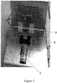
- Figure 3 shows a representative liquid dispensing device in which the reaction vessel has been removed showing a geared motor (7), cam (8), and reaction vessel clips (9).
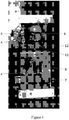
- Figure 4 shows the underside of a representative liquid dispensing device showing four reservoir control valves (4), a geared motor (7), a cam (8), a multi-way connector (12), and various connection tubing (13) and wiring.
- the wash buffer reservoir (1) may serve as a chamber into which a wash buffer is poured. Any wash buffer can be used.
- the wash buffer reservoir can be of any shape and size, but is generally designed to hold from about 50 ml to about 500 ml, from about 100 ml to about 400 ml, or from about 200 ml to about 300 ml of liquid.
- the wash buffer reservoir also comprises a port (not shown), which serves as an opening into which the wash buffer can leave the wash buffer reservoir.
- the port can be located anywhere in the bottom of the wash buffer reservoir.
- the port may be located on the bottom of the wash buffer reservoir at one end of the reservoir.
- the wash buffer reservoir may be designed to be removable and allow complete drainage by gradients in the floor of the tray.
- the liquid dispensing device of the present invention comprises at least one reagent reservoir (2, 3).
- the device may comprise two or three reagent reservoirs (i.e., a primary reagent reservoir and a secondary reagent reservoir).
- Each reagent reservoir serves as a chamber into which various reagents are poured. Any reagent can be used. Suitable reagents include, for example, primary and secondary antibodies used for detection.
- the reagent reservoirs can be of any shape and size, but are generally designed to be at least 1 cm, at least 2 cm, or at least 4 cm in height, and/or designed to contain up to 0.5 ml, up to 2 ml, up to 5 ml, up to 10 ml, up to 20 ml, or up to 50 ml of reagent.
- Each reagent reservoir also comprises a port (not shown), which serves as an opening into which the reagent can leave the reagent reservoir.
- the port can be located anywhere in the bottom of the reagent reservoir. In part because the primary and secondary reagents are generally expensive, and thus small volumes (1 to 10 ml) are usually employed.
- the liquid dispensing device of the present invention comprises a reaction vessel (5) which serves as a chamber into which a membrane can be placed. Any membrane, including PVDF and nitrocellulose membranes, can be used.
- the reaction vessel may also be used to contain various buffers, such as a blocking solution, that are added for a particular protocol.
- the reaction vessel can be of any shape and size, but is generally designed to hold a square or rectangular piece of membrane that is from about 5 cm to about 30 cm, from about 8 cm to about 20 cm, or from about 10 cm to about 15 cm in size.
- the reaction vessel is also designed to hold from about 0.5 ml to about 100 ml, from about 2 ml to about 75 ml, from about 5 ml to about 20 ml, or from about 8 ml to about 20 ml of liquid.
- the reaction vessel comprises one or a plurality of baffles.
- the baffles may be of any shape and may be of any length to fit inside the reaction vessel, each baffle being substantially parallel to one or more other baffles.
- the reaction vessel further comprises a first port (6) (see, Figure 2 ), which can serve as an opening into which any fluids can enter the reaction vessel from the either or both the wash buffer reservoir and/or the reagent reservoir(s).
- the first port can be located anywhere in the side of the reaction vessel or may simply be the opening of the reaction vessel at the top.
- the reaction vessel may comprise a second port (22) (see, Figures 6 , 7 , and 8 ), which serves as an opening in the reaction vessel into which any fluids that are within the reaction vessel can exit the reaction vessel.
- the second port of the reaction vessel may be located on the bottom of the reaction vessel at one end of the reaction vessel.
- the baffles also retain the membrane in the fluid area while stopping it from obstructing the second port in the reaction vessel.
- the reaction vessel may be asymmetric in regard to the second port and axis of rotation of the reaction vessel.
- the reaction vessel may comprise a plurality of analysis sections, which can each comprise a separate membrane.
- the reaction vessel can be made out of low friction plastic or a low friction plastic strip is adhered to its bottom base to interact with the cam.
- the reaction vessel design is not limited to that in any of the figure disclosed herein; other designs are possible which may have smaller or larger surface area and volume, or contain a cylinder of material that acts as a dispersal mechanism for low ( ⁇ 5 ml) of liquid, or contain multiple chambers for incubating membranes of different size or number.
- the reaction vessel may be held in place by one or more reaction vessel clips (9) (see, Figure 3 ).
- the wash buffer reservoir and the at least one reagent reservoir are each in fluid communication with the reaction vessel.
- fluids may flow from the wash buffer reservoir to the reaction vessel, and can do so merely by gravitational forces in devices without a central pump.
- fluids may flow from the at least one reagent reservoir to the reaction vessel, and can do so merely by gravitational forces in devices without a central pump.
- Fluids leave the wash buffer reservoir and the at least one reagent reservoir through their respective ports, as described above.
- the fluid(s) leaving the wash buffer reservoir and/or the at least one reagent reservoir enter the reaction vessel through the first port of the reaction vessel.
- Each port of the wash buffer reservoir and the at least one reagent reservoir are in fluid communication via tubing with the first port of the reaction vessel.
- the fluid communication is carried out by tubing.
- Each tubing may be about 3.175 mm (1/8 inch) internal diameter and about 4.76 mm (3/16 inch) outside diameter. Any tubing can be used.
- the tubing may be smoothly contoured so that resistance is not increased by kinks.
- Figure 4 shows tubing (13) connecting one portion of the device to another portion of the device.
- the flow of fluid from either or both of the wash buffer reservoir and the at least one reagent reservoir to the reaction vessel is controlled with one or more reservoir control valves (4), and the central pump (27).
- the reservoir control valve for the wash buffer reservoir may control the opening and closing of the port of the wash buffer reservoir.
- the reservoir control valve for the wash buffer reservoir may be an in-line component of the tubing from the wash buffer reservoir to the reaction vessel, and thus control the flow of fluid once in the tubing.
- the reservoir control valve(s) for the at least one reagent reservoir(s) and the central pump may control the opening and closing of the port(s) of the reagent reservoir(s).
- the reservoir control valve for the at least one reagent reservoir(s) may be in-line component(s) of the tubing from the at least one reagent reservoir to the reaction vessel, and thus control the flow of fluid once in the tubing.
- the central pump is in electronic communication with the control board and can act to pull or push fluid through the various ports and tubing in the device.
- the central pump may also be in communication with a power source.
- the port of the at least one reagent vessel and the port of the wash buffer reservoir may be both at least 0.5 cm higher, at least 1 cm higher, at least 2 cm higher, at least 3 cm higher, at least 4 cm higher, or at least 5 cm higher than each of the respective reservoir control valves.
- Each of the reservoir control valves may be at least 0.5 cm higher, at least 1 cm higher, at least 2 cm higher, at least 3 cm higher, at least 4 cm higher, or at least 5 cm higher than the first port of the reaction vessel.
- the tubing leaving the respective reservoir control valves may converge to a multi-way connector (12) (see, Figure 4 ).
- the multi-way connector is in fluid communication with the central pump and reaction vessel by additional tubing which enters the reaction vessel by the first port of the reaction vessel or simply disposes its contents into the opening for the reaction vessel.
- the multi-way connector may be a 4-way connector.
- the multi-way connector that receives the reservoir solutions may be mounted at an angle and close to the reaction vessel.
- the waste tray serves as a chamber into which the fluid from the reaction vessel drains.
- the waste tray can be of any shape and size, but is generally designed to hold from about 100 ml to about 2000 ml, from about 150 ml to about 1500 ml, from about 200 to about 800 ml, or from about 250 ml to about 400 ml of fluid.
- the waste tray may comprise a port, which serves as an opening into which the fluid from the reaction vessel (through the second port thereof) can enter the waste tray.
- the port can be located anywhere in the top portion of the waste tray.
- the waste tray is in fluid communication with the reaction vessel by tubing.
- the second port of the reaction vessel may be at least 0.5 cm higher, at least 1 cm higher, at least 2 cm higher, at least 3 cm higher, at least 4 cm higher, or at least 5 cm higher than the port in the waste tray.
- the flow of fluid from the reaction vessel to the waste tray reaction may be controlled with a reaction vessel control valve (23) (see, Figure 2 ).
- the reaction vessel control valve may control the opening and closing of the second port of the reaction vessel.
- the reaction vessel control valve may be an in-line component of the tubing from the reaction vessel to the waste tray, and thus control the flow of fluid once in the tubing.
- the devices further comprise a cam (8), powered by a geared motor (7), in physical connection with the reaction vessel.
- the cam is designed to tilt the reaction vessel from one to four times, or twice, for every rotation of the motor output.
- the cam can also use 1, 2, 3, 4, 5 or more high points for tilting.
- the motor output may rotate at about 40 rpm with 12 V power and, therefore, the tilting up and down cycle may be performed twice per revolution and 80 times per minute, but the frequency is not limited to this rate and can also be higher or lower.
- the cam can be made out of low friction plastic which interacts with the underside of the reaction vessel which can also be interfaced with low friction plastic and, thus, create a low friction tilting mechanism.
- the cam comprises an off-set shape.
- the reaction vessel is tethered at one end and is positioned to rock up and down at the distal end (i.e., non-tethered end) by interaction with the cam.
- the reaction vessel may be designed to tilt back and forth through a small angle with an axis on one end of the vessel.
- the tilting amplitude is helpful for a good waveform to maintain appropriate liquid movement across the membrane which improves detection of analytes and reduces background signals.
- the reaction vessel may further comprise a cylinder that moves up and down with the action of the cam.
- a simple geared motor with low friction plastic cam creates a low friction tilting mechanism which is programmed to be on at the beginning of the routine and off at the end. Thus, an on/off control switch for tilting need not be required.
- the motor is in electronic communication with the control board and with a power source (not shown).
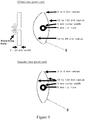
- Figure 5 shows representative cam designs and the reaction vessel wave indicating asymmetric and symmetric two point cam design.
- Each of the cams can be from about 2 to about 20 mm in width and can have a variety of radius designs from which to select, depending upon the degree of tilt desired for the reaction vessel.
- the asymmetric design creates good drainage and a good waveform by spending more time in the tilted up position and a rapid drop to the lowest level which creates a wave in the liquid which can be desirable compared to constant tilting without a wave.
- the asymmetric cam can be made in various shapes such as: the two high points having a radius which is 3 mm wider than the second highest point which is at right angles to them, the second highest point having a radius which is 2 mm wider than the lowest point which is opposite the second highest point. If the reaction tray is considered in a reference location when it is horizontal (no tilt), then the high point of the tilt is 9 mm above horizontal, the second high point is 2 mm above horizontal and the lowest point is 2 mm below horizontal. The design of the cam allows these different tilt amplitudes to occur. Other radii can be used to create different tilting amplitudes and frequencies.
- Figures 6 , 7 , and 8 show representative designs for the reaction vessel and how it interacts with other components in the liquid dispending device.
- the introduction of fluid may be from the multi-way connector which directs fluid into the reaction vessel from above (where the first port is actually the opening to the reaction vessel).
- the membrane and fluid are agitated in the reaction vessel by tilting, and the baffles keep the membrane out of the way of the second port drain which is located at the axis of rotation. Because of the cam shape, the reaction vessel can be tilted up at its distal end for the majority of the tilting cycle, which aids the drainage of fluid to the waste tray.
- a first reaction vessel design is shown.
- the basic design has a flat lower surface with baffles (14) separating the membrane probing area (15) from the second port (22) of the reaction vessel, and the axis of rotation is in the location of the tray retaining clips next to the chassis bulk head end.
- the tray tilts down only 1 or 2 mm at its distal end and upward by 8 to 10 mm. Other tilting angles and amplitudes are possible and work well.
- the reaction vessel may comprise one or more clips in legs (17), as shown on the bulk head end.
- reaction vessel designs are possible which allow for smaller volumes of SAR, different sizes and numbers of membranes (e.g., the use of a plastic cylinder as a dispersal mechanism for small volumes (see, Figure 7 ) or using, for example, fifteen mini-chambers for incubating strips of 0.3 cm x 8 cm within one reaction vessel (see, Figure 8 ).
- a second reaction vessel design is shown.
- the small volume of SAR is necessary in some cases where SAR is limiting (e.g., with expensive antibody solutions or when using mouse serum).
- This design incorporates a plastic cylinder (19) which is suitably heavy and of sufficient diameter to roll up and down the reaction vessel on top of the membrane when the vessel is inclined up and down. Liquid volumes as low as 1 ml of SAR can be evenly spread across a normal sized membrane thus saving valuable reagent.
- Separators (18) may be located at the distal end to stop surface tension causing the cylinder to adhere to the wall of the vessel.
- a third reaction vessel design is shown.
- the operator may need to measure the activity of antibodies in very small volumes (e.g., 200 ⁇ l or less).
- the reaction vessel has individual mini-chambers separated by walls (20), and optionally a dam (21) to stop the SAR solution moving out of a mini-chamber and mixing with the others.
- a large volume (e.g., 20 ml or more) of wash buffer flows over the dam and into the whole reaction vessel and immediately drains out of the second port, thus not allowing time for SARs to contaminate each other's chamber.
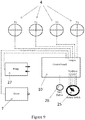
- Each control valve may in electrical communication with an electronic control board (10) (see, Figure 9 ), which may comprise a start button (26), which can be utilized to start a particular routine, and a rotary switch (25), which can be used to select a particular routine.
- the electronic control board controls the opening and closing of each control valve (4) (see V1, V2, V3, V4, P1 in Figure 9 ) and fluid pumping and controls the length of time that each control valve is opened, and thus the volume of fluid being transported.
- the electronic control board may be commercially available, such as, for example, iOS Uno or Mega, or the like. One or more of the control valves may be operated manually.
- the electronic control board may contain software that is programmable to carry out particular routines to control the sequence of control valve opening and closing and the length of time each control valve is opened.
- the control board may have a power switch to control the operation of the motor for the cam.
- the electronic control board may be programmable to control the speed of the motorized cam.
- the electronic control board may further comprise a communication port, such as a USB port for ISO9000 type compliance, for another device.
- the USB port may be included for ISO9000-type reporting of the device's events during a particular procedure.
- the electronic control board may comprise Bluetooth remote control capability, which can allow for remote programming and control of the device.
- control software program for the control board is very flexible with all steps being able to be modified and reprogrammed.
- a short list of routines can cover a majority of practical procedures.
- a basic program design which incorporates this short list can simplify the interface with the end user by providing several push buttons or a rotary switch with several positions.
- one routine provides the opportunity to treat the membrane with just two reagents (e.g., wash and primary reagent) which gives flexibility for other applications such as probing with a pre-labeled primary reagent.
- the pre-programmed routines can be varied in time and number of steps.
- the devices disclosed herein can be compact and portable.
- the entire device may be less than 30 cm x 50 cm, less than 20 cm x 30 cm, or less than 16 cm x 24 cm, and weighs less than 10 kg, or less than 5 kg, or less than 2 kg.
- the device may be about 15 cm x about 22 cm.
- a chassis may connect each of the wash buffer reservoir, reagent reservoir(s), reaction vessel, wash tray, and cam motor and is also the exterior shell of the device.
- the device may comprise rounded corners, high sloping walls, and/or lower walls that are mainly vertical to allow close packing.
- the reaction vessel is tilted with an asymmetric amplitude to create a waveform in the fluid which can be adjusted, by placement of the cam from a centered position to any one of a number of off-center placements. This allows for agitation and improved analyte detection, and also aids the draining of fluids at the end of each step.
- the present disclosure also provides a system that comprises a plurality of any one or more of the devices disclosed herein.
- the system may be controlled by a single electronic control board which controls all valves, motors, and central pumps, of each device.
- a wash buffer may be loaded into the wash buffer reservoir.
- a first reagent may be loaded into one of the at least one reagent reservoirs.
- a second reagent is optionally loaded into a different one of the at least one reagent reservoirs.
- the membrane and blocking reagent may be placed into the reaction vessel.
- a routine from the electronic control board may be selected and run for a predetermined amount of time.
- the membrane may be removed from the reaction vessel for subsequent signal development and result acquisition.
- the operator will previously have an analyte bound-membrane from a Western Blot experiment, and will have prepared four solutions: 1) blocking reagent (20 ml), 2) wash buffer (300 ml), 3) SAR (5 ml), and 4) secondary amplifying reagent (15 ml).
- the operator will add the wash buffer into the wash buffer reservoir, and the primary and secondary reagents into their appropriate reagent reservoirs. Then the membrane may be placed in the reaction vessel and the blocking solution is poured over it.
- the desired routine may be chosen by pressing a switch and the routine runs without interruption.
- the operator can return after about 4 hours (or when the routine ends) or the full length of time of another routine and remove the membrane for subsequent signal development and result acquisition by any of the known methods.
- the operator can remove excess wash buffer remaining in the wash buffer reservoir and apply nanopure water to any of the reservoirs and run a programmed wash routine which preserves the components for future use.
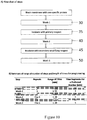
- FIG. 10A a representative flow chart of standard operating procedure with variable aspects is shown.
- the flow chart represents typical steps in a standard operating procedure. For example, a blocked membrane is washed (30), incubated with primary reagent (35), washed (40), incubated with secondary reagent (45), and washed again (50).
- Figure 10B shows a typical range of variations in Western blots and an exemplary routine programmed into the controller.
- Example 1 Western Blot (actual example)
- a typical western blot procedure was performed. First, a membrane was prepared which contained the adhered proteins, which were separated by electrophoresis using an SDS containing polyacrylamide gel. Several protein containing samples were prepared; ten lanes were loaded with: 1) molecular weight marker (MWM) (lane 1); 2) various amounts of purified recombinant RhoA protein (RH01) (lanes 2 to 7); and 3) various amounts of platelet cell protein extract (lanes 8, 9, and10). Electrophoresis was performed at 150V for 1.5 hours. The gel was placed into blotting buffer containing 25 mM Tris base, 180 mM glycine, and 15% methanol in nanopure water to equilibrate.
- the gel was then sandwiched between filter paper and the membrane on the positively charged side of the gel (SDS surrounded proteins migrate towards the positive terminal) and electroblotting was performed at 350 mA for 45 minutes.
- the membrane was transferred to a device as set forth herein and the following protocol was carried out.
- Phosphate Buffered Saline plus Tween 20 (PBST): 1.44 g Na 2 HPO 4 , 0.24 g KH 2 PO 4 , 0.20 g KCl, 8 g NaCl, 995 ml nanopure water; mixed until dissolved and pH to 7.4 with 1M HCl; 2) Blocking Solution: 1 g (5% w/v) dry milk powder in 20 ml of PBST; 3) Primary Antibody in PBST: 5 ⁇ l of anti-RhoA (Cat.
- the device was turned on and the rotary knob turned to the protocol number 1 which is a normal routine for Western Blots. All valves were in the closed position at the start of the routine.
- Three hundred (300) ml of PBST was poured into the wash buffer reservoir.
- Twenty (20) ml of blocking solution was poured into the reaction vessel and the membrane was added to this solution.
- the primary antibody (in 5 ml solution) was poured into the first reagent reservoir, and the secondary antibody (in 20 ml solution) was poured into a second reagent reservoir.
- the routine was started by pressing the start button.
- the membrane was removed from the reaction vessel and placed on a paper towel.
- the membrane was dabbed dry and placed on a piece of 4 mil polythene, to which 1 ml of HRP detection reagent (e.g. Cat. # 34076 from ThermoFisher Scientific Inc., MA, USA) was pipetted on to the membrane to develop the chemiluminescent signal.
- HRP detection reagent e.g. Cat. # 34076 from ThermoFisher Scientific Inc., MA, USA
- Another layer of polyurethane was sandwiched on top. The polyurethane-membrane sandwich was placed into a dark camera chamber and an image was taken (see, Figure 11 for results).
- RhoA Detection of purified recombinant RhoA at 28 kDal molecular weight with a 10 ng detection limit was observed at a 30 second exposure, and down to 5 ng at a 5 minute exposure. The detection of native RhoA at 21 kDal molecular weight was observed where approximately 10 ng of RhoA was detected in 40 ⁇ g of platelet cell extract. The dark background was indicative of very good washing of the membrane between incubation steps.
- the first versions contains what the operator sees, whereas the second version contains the software program valve timings.
Landscapes
- Chemical & Material Sciences (AREA)
- Chemical Kinetics & Catalysis (AREA)
- Analytical Chemistry (AREA)
- Health & Medical Sciences (AREA)
- Clinical Laboratory Science (AREA)
- Apparatus Associated With Microorganisms And Enzymes (AREA)
- Sampling And Sample Adjustment (AREA)
- Automatic Analysis And Handling Materials Therefor (AREA)
Claims (14)
- Dispositif de distribution de liquide, comprenant :un réservoir de tampon de lavage (1) et au moins un réservoir de réactif (2, 3), chaque réservoir comprenant une vanne de commande de réservoir (4), dans lequel chaque vanne de commande de réservoir (4) est en communication électrique avec une carte de commande électronique (10) ;un récipient à réaction (5) en communication fluidique avec le réservoir de tampon de lavage (1) et le ou les réservoirs de réactif (2, 3), dans lequel le récipient à réaction (5) comprend un ou plusieurs déflecteurs (14) ;un bac à résidus en communication fluidique avec le récipient à réaction (5) ;une came asymétrique excentrée, motorisée (8), alimentée par un moteur à train d'engrenages (7), en connexion physique avec le récipient à réaction (5), la came (8) étant conçue pour incliner le récipient à réaction (5) d'une à quatre fois pour chaque rotation de la sortie de moteur et/ou le récipient à réaction (5) étant attaché au niveau d'une extrémité et positionné pour remonter et redescendre au niveau de l'extrémité distale par une interaction avec la came (8) ; et une pompe centrale (27),dans lequeli) le moteur à train d'engrenages (7) et la pompe centrale (27) sont en communication électrique avec la carte de commande électronique (10),ii) l'écoulement d'un fluide depuis le réservoir de tampon de lavage (1) et/ou le ou les réservoirs de réactif (2, 3) jusqu'au récipient à réaction (5) est régulé avec une ou plusieurs vannes de commande de réservoir (4) et la pompe centrale (27) par la carte de commande électronique (10) ;iii) chacun des réservoirs de tampon de lavage (1) et au moins un réservoir de réactif (2, 3) comprennent un orifice qui est en communication fluidique avec un premier orifice (6) du récipient à réaction (5) ;iv) chacun de l'orifice du réservoir de tampon de lavage (1) et de l'orifice du ou des réservoirs de réactif (2, 3) sont en communication fluidique au moyen de tuyaux avec le premier orifice (6) du récipient à réaction (5) ; etv) le tuyau (13) à partir du réservoir de tampon de lavage (1) et le tuyau à partir du ou des réservoirs de réactif (2, 3) sont en communication fluidique avec un connecteur multiplie (12) et la pompe centrale (27).
- Dispositif selon la revendication 1, dans lequel l'orifice du ou des réservoirs de réactif (2, 3) et l'orifice du réservoir de tampon de lavage (1) sont au moins 0,5 cm plus hauts, au moins 1 cm plus hauts ou au moins 2 cm plus hauts que chacune des vannes de commande de réservoir (4).
- Dispositif selon la revendication 1 ou la revendication 2, dans lequel chacune des vannes de commande de réservoir (4) est au moins 0,5 cm plus haute, au moins 1 cm plus haute ou au moins 2 cm plus haute que le premier orifice (6) du récipient à réaction (5).
- Dispositif selon l'une quelconque des revendications précédentes, dans lequel chaque vanne de commande de réservoir (4) soit commande les orifices du réservoir de tampon de lavage (1) et le ou les réservoirs de réactif (1), soit commande la communication fluidique à l'intérieur du tuyau respectif (13).
- Dispositif selon l'une quelconque des revendications précédentes, dans lequel le connecteur multiplie (12) est en communication fluidique avec le récipient à réaction (5) au moyen d'un tuyau (13).
- Dispositif selon l'une quelconque des revendications précédentes, dans lequel un orifice dans le bac à résidus est en communication fluidique avec un second orifice (22) dans le récipient à réaction (5) au moyen d'un tuyau (13).
- Dispositif selon la revendication 6, dans lequel le second orifice (22) dans le récipient à réaction (5) est au moins 0,5 cm plus haut, au moins 1 cm plus haut ou au moins 2 cm plus haut que l'orifice dans le bac à résidus.
- Dispositif selon la revendication 6 ou la revendication 7, dans lequel une vanne de commande de récipient à réaction (4) soit commande le second orifice (22) du récipient à réaction (5), soit commande la communication fluidique à l'intérieur du tuyau (13) allant du récipient à réaction (5) au bac à résidus.
- Dispositif selon l'une quelconque des revendications précédentes, dans lequel la carte de commande électronique (10) commande l'ouverture et la fermeture de chaque vanne de commande (4), active et désactive la pompe centrale (27) et commande le laps de temps pendant lequel chaque vanne de commande (4) est ouverte.
- Dispositif selon la revendication 9, dans lequel la carte de commande électronique (10) contient un logiciel qui peut être programmé pour commander la séquence d'ouverture et de fermeture d'une vanne de commande (4) et le laps de temps pendant lequel chaque vanne de commande (4) est ouverte.
- Dispositif selon l'une quelconque des revendications précédentes, dans lequel(i) la carte de commande électronique (10) peut être programmée pour réguler la vitesse de la came motorisée (8) ; et/ou(ii) comprenant en outre un port de communication pour une conformité aux normes ISO9000 ; et/ou(iii) la carte de commande électronique (10) comporte une fonctionnalité de commande à distance Bluetooth ; et/ou(iv) le récipient à réaction (5) comprend en outre un cylindre qui se déplace vers le haut et vers le bas avec l'action de la came ; et/ou(v) le récipient à réaction (5) comprend une pluralité de sections d'analyse ; et/ou(vi) le dispositif entier est inférieur à 30 cm x 50 cm, inférieur à 20 cm x 30 cm ou inférieur à 16 cm x 24 cm et pèse moins de 10 kg, ou moins de 5 kg ou moins de 2 kg ; et/ou(vii) chaque tuyau (13) présente un diamètre interne de 0,3175 cm (1/8 pouce) et un diamètre externe d'environ 0,47625 cm (3/16 pouce) ; et/ou(viii) le réservoir de réactif ou chacun des réservoirs de réactif (2, 3) comprend un intérieur qui peut contenir jusqu'à 5 ml, jusqu'à 10 ml ou jusqu'à 20 ml de réactif ; et/ou(ix) un châssis relie le réservoir de tampon de lavage (1) et le ou les réservoirs de réactif (2, 3) et le récipient à réaction (5) et le bac à résidus et le moteur à cames (8) et constitue également la coque extérieure du dispositif.
- Dispositif selon la revendication 6, 7 ou 8, dans lequel le récipient à réaction (5) est asymétrique par rapport au second orifice (22) et à l'axe de rotation du récipient à réaction (5).
- Système pour la distribution d'un liquide comprenant une pluralité de dispositifs selon l'une quelconque des revendications précédentes.
- Procédé d'analyse d'une membrane à l'aide du dispositif selon l'une quelconque des revendications 1 à 12 consistant :à charger un tampon de lavage dans le réservoir de tampon de lavage (1) ;à charger un premier réactif dans le réservoir de réactif ou dans l'un des réservoirs de réactif (2, 3) ;à charger un second réactif dans un autre réservoir de réactif ou dans un autre des réservoirs de réactif (2, 3) ;à charger la membrane et à bloquer un réactif dans le récipient à réaction (5) ;à sélectionner une routine à partir de la carte de commande électronique (10) ; età enlever la membrane du récipient à réaction (5) pour d'un développement de signal ultérieur et d'une acquisition de résultat.
Applications Claiming Priority (1)
| Application Number | Priority Date | Filing Date | Title |
|---|---|---|---|
| PCT/US2014/065713 WO2016076888A1 (fr) | 2014-11-14 | 2014-11-14 | Dispositifs modulaires de distribution de fluides |
Publications (3)
| Publication Number | Publication Date |
|---|---|
| EP3218112A1 EP3218112A1 (fr) | 2017-09-20 |
| EP3218112A4 EP3218112A4 (fr) | 2018-05-09 |
| EP3218112B1 true EP3218112B1 (fr) | 2020-09-02 |
Family
ID=55954800
Family Applications (1)
| Application Number | Title | Priority Date | Filing Date |
|---|---|---|---|
| EP14905798.6A Active EP3218112B1 (fr) | 2014-11-14 | 2014-11-14 | Dispositifs modulaires de distribution de fluides |
Country Status (3)
| Country | Link |
|---|---|
| EP (1) | EP3218112B1 (fr) |
| CN (1) | CN106999936A (fr) |
| WO (1) | WO2016076888A1 (fr) |
Family Cites Families (17)
| Publication number | Priority date | Publication date | Assignee | Title |
|---|---|---|---|---|
| US4585623A (en) | 1984-02-27 | 1986-04-29 | Allelix Inc. | Device for performing quantitative chemical and immunochemical assays |
| US4859419A (en) | 1987-02-27 | 1989-08-22 | American Bionetics, Inc. | Diagnostic manifold apparatus |
| US4989755A (en) * | 1988-12-20 | 1991-02-05 | Shiau Guey Chuan | Automatic cleaning-liquid dispensing device |
| AU635008B2 (en) | 1989-12-13 | 1993-03-11 | Genelabs Diagnostics Pte Ltd | Analytical apparatus and method for automated blot assay |
| US5559032A (en) | 1990-06-29 | 1996-09-24 | Pomeroy; Patrick C. | Method and apparatus for post-transfer assaying of material on solid support |
| US5674006A (en) * | 1996-03-27 | 1997-10-07 | Hoefer Pharmacia Biotech, Inc. | Fluid circulation apparatus |
| US6194160B1 (en) | 1998-03-19 | 2001-02-27 | Immunetics, Inc. | Systems and methods for rapid blot screening |
| US7708946B1 (en) | 2001-07-19 | 2010-05-04 | Michael Sherman | Device for protein detecting tests |
| US7964413B2 (en) * | 2005-03-10 | 2011-06-21 | Gen-Probe Incorporated | Method for continuous mode processing of multiple reaction receptacles in a real-time amplification assay |
| US8261950B2 (en) * | 2007-10-22 | 2012-09-11 | Georgia-Pacific Consumer Products Lp | Pumping dispenser |
| JP5492207B2 (ja) | 2008-08-27 | 2014-05-14 | ライフ テクノロジーズ コーポレーション | 生物学的サンプルの処理装置および処理方法 |
| CN101923096B (zh) * | 2009-06-12 | 2013-01-02 | 上海迅达医疗仪器有限公司 | 自动蛋白印迹分析仪 |
| CN101833007B (zh) * | 2010-02-25 | 2013-04-03 | 上海迅达医疗仪器有限公司 | 一种蛋白印迹检测装置 |
| EP2567242B1 (fr) | 2010-05-06 | 2022-03-02 | Precision Biosystems LLC | Système de distribution de fluide et appareil de distribution de fluide |
| CN203069607U (zh) * | 2013-01-23 | 2013-07-17 | 深圳市亚辉龙生物科技有限公司 | 一种蛋白印迹自动检测装置 |
| US9468895B2 (en) * | 2013-04-02 | 2016-10-18 | Forward Biotech, Inc. | Advanced laboratory platform rocker |
| CN104007270B (zh) * | 2014-03-20 | 2016-08-17 | 欧蒙医学诊断(中国)有限公司 | 一种生物检测的分析设备 |
-
2014
- 2014-11-14 EP EP14905798.6A patent/EP3218112B1/fr active Active
- 2014-11-14 WO PCT/US2014/065713 patent/WO2016076888A1/fr not_active Ceased
- 2014-11-14 CN CN201480082500.2A patent/CN106999936A/zh active Pending
Non-Patent Citations (1)
| Title |
|---|
| None * |
Also Published As
| Publication number | Publication date |
|---|---|
| EP3218112A4 (fr) | 2018-05-09 |
| WO2016076888A1 (fr) | 2016-05-19 |
| CN106999936A (zh) | 2017-08-01 |
| EP3218112A1 (fr) | 2017-09-20 |
Similar Documents
| Publication | Publication Date | Title |
|---|---|---|
| JP5266208B2 (ja) | 液滴処置システム | |
| JP3505689B2 (ja) | カプセル化学試料液体分析装置及び分析法 | |
| US20100300563A1 (en) | Modular device and method for moving fluids to and from a sample delivery element | |
| JP2018529942A (ja) | モジュール式液体取り扱いシステム | |
| JP3525757B2 (ja) | 化学分析装置 | |
| US6562209B1 (en) | Automated computer controlled reporter device for conducting imunnoassay and molecular biology procedures | |
| JP2008536128A (ja) | 自動化微小体積アッセイシステム | |
| JP2008539440A (ja) | 自動臨床アナライザで少量で液体サンプルを吸引若しくは分配する方法および装置 | |
| JP2007524081A (ja) | モジュール式試薬給送手段を使用することによって自動臨床アナライザの性能を向上させる方法 | |
| US9468895B2 (en) | Advanced laboratory platform rocker | |
| TW201213808A (en) | Chemical or biochemical analysis apparatus and method for chemical or biochemical analysis | |
| JP7640602B2 (ja) | 変調式空気ジェットを使用する非接触混合 | |
| CN105556316A (zh) | 使用自动分析器执行对样品中的分析物的测量的方法 | |
| US20190324049A1 (en) | Modular Fluid Dispensing Devices | |
| EP3218112B1 (fr) | Dispositifs modulaires de distribution de fluides | |
| US7708946B1 (en) | Device for protein detecting tests | |
| US20130122606A1 (en) | Method and device for chemical and/or biological analysis | |
| US11808778B2 (en) | Intelligent pressure control apparatus and methods for maintaining manifold pressure in a diagnostic testing apparatus | |
| US11255868B2 (en) | Fluid control equipment for bio-reaction, bio-reaction system and fluid control method for bio-reaction | |
| JP2004101541A (ja) | 化学分析装置 | |
| EP4429822A1 (fr) | Procédé et kit de criblage pour diagnostic rapide et kit et machine jetables associés | |
| WO2009155935A1 (fr) | Cartouche et système pour l'automatisation de la manipulation de liquides | |
| WO2017163567A1 (fr) | Dispositif de décharge de solution et procédé de commande de décharge de solution |
Legal Events
| Date | Code | Title | Description |
|---|---|---|---|
| STAA | Information on the status of an ep patent application or granted ep patent |
Free format text: STATUS: THE INTERNATIONAL PUBLICATION HAS BEEN MADE |
|
| PUAI | Public reference made under article 153(3) epc to a published international application that has entered the european phase |
Free format text: ORIGINAL CODE: 0009012 |
|
| STAA | Information on the status of an ep patent application or granted ep patent |
Free format text: STATUS: REQUEST FOR EXAMINATION WAS MADE |
|
| 17P | Request for examination filed |
Effective date: 20170525 |
|
| AK | Designated contracting states |
Kind code of ref document: A1 Designated state(s): AL AT BE BG CH CY CZ DE DK EE ES FI FR GB GR HR HU IE IS IT LI LT LU LV MC MK MT NL NO PL PT RO RS SE SI SK SM TR |
|
| AX | Request for extension of the european patent |
Extension state: BA ME |
|
| DAX | Request for extension of the european patent (deleted) | ||
| A4 | Supplementary search report drawn up and despatched |
Effective date: 20180411 |
|
| RIC1 | Information provided on ipc code assigned before grant |
Ipc: B01F 11/00 20060101ALN20180405BHEP Ipc: B01L 3/02 20060101AFI20180405BHEP Ipc: G01N 33/543 20060101ALN20180405BHEP |
|
| STAA | Information on the status of an ep patent application or granted ep patent |
Free format text: STATUS: EXAMINATION IS IN PROGRESS |
|
| 17Q | First examination report despatched |
Effective date: 20190102 |
|
| GRAP | Despatch of communication of intention to grant a patent |
Free format text: ORIGINAL CODE: EPIDOSNIGR1 |
|
| STAA | Information on the status of an ep patent application or granted ep patent |
Free format text: STATUS: GRANT OF PATENT IS INTENDED |
|
| RIC1 | Information provided on ipc code assigned before grant |
Ipc: B01L 3/02 20060101AFI20191008BHEP Ipc: B01F 11/00 20060101ALN20191008BHEP Ipc: G01N 33/543 20060101ALN20191008BHEP |
|
| INTG | Intention to grant announced |
Effective date: 20191111 |
|
| RIC1 | Information provided on ipc code assigned before grant |
Ipc: B01L 3/02 20060101AFI20191029BHEP Ipc: B01F 11/00 20060101ALN20191029BHEP Ipc: G01N 33/543 20060101ALN20191029BHEP |
|
| GRAS | Grant fee paid |
Free format text: ORIGINAL CODE: EPIDOSNIGR3 |
|
| GRAJ | Information related to disapproval of communication of intention to grant by the applicant or resumption of examination proceedings by the epo deleted |
Free format text: ORIGINAL CODE: EPIDOSDIGR1 |
|
| GRAL | Information related to payment of fee for publishing/printing deleted |
Free format text: ORIGINAL CODE: EPIDOSDIGR3 |
|
| STAA | Information on the status of an ep patent application or granted ep patent |
Free format text: STATUS: EXAMINATION IS IN PROGRESS |
|
| GRAP | Despatch of communication of intention to grant a patent |
Free format text: ORIGINAL CODE: EPIDOSNIGR1 |
|
| STAA | Information on the status of an ep patent application or granted ep patent |
Free format text: STATUS: GRANT OF PATENT IS INTENDED |
|
| INTC | Intention to grant announced (deleted) | ||
| INTG | Intention to grant announced |
Effective date: 20200323 |
|
| RIC1 | Information provided on ipc code assigned before grant |
Ipc: B01F 11/00 20060101ALN20200313BHEP Ipc: G01N 33/543 20060101ALN20200313BHEP Ipc: B01L 3/02 20060101AFI20200313BHEP |
|
| GRAA | (expected) grant |
Free format text: ORIGINAL CODE: 0009210 |
|
| STAA | Information on the status of an ep patent application or granted ep patent |
Free format text: STATUS: THE PATENT HAS BEEN GRANTED |
|
| AK | Designated contracting states |
Kind code of ref document: B1 Designated state(s): AL AT BE BG CH CY CZ DE DK EE ES FI FR GB GR HR HU IE IS IT LI LT LU LV MC MK MT NL NO PL PT RO RS SE SI SK SM TR |
|
| REG | Reference to a national code |
Ref country code: GB Ref legal event code: FG4D |
|
| REG | Reference to a national code |
Ref country code: AT Ref legal event code: REF Ref document number: 1308208 Country of ref document: AT Kind code of ref document: T Effective date: 20200915 Ref country code: CH Ref legal event code: EP |
|
| REG | Reference to a national code |
Ref country code: DE Ref legal event code: R096 Ref document number: 602014069883 Country of ref document: DE |
|
| REG | Reference to a national code |
Ref country code: IE Ref legal event code: FG4D |
|
| REG | Reference to a national code |
Ref country code: LT Ref legal event code: MG4D |
|
| PG25 | Lapsed in a contracting state [announced via postgrant information from national office to epo] |
Ref country code: GR Free format text: LAPSE BECAUSE OF FAILURE TO SUBMIT A TRANSLATION OF THE DESCRIPTION OR TO PAY THE FEE WITHIN THE PRESCRIBED TIME-LIMIT Effective date: 20201203 Ref country code: NO Free format text: LAPSE BECAUSE OF FAILURE TO SUBMIT A TRANSLATION OF THE DESCRIPTION OR TO PAY THE FEE WITHIN THE PRESCRIBED TIME-LIMIT Effective date: 20201202 Ref country code: HR Free format text: LAPSE BECAUSE OF FAILURE TO SUBMIT A TRANSLATION OF THE DESCRIPTION OR TO PAY THE FEE WITHIN THE PRESCRIBED TIME-LIMIT Effective date: 20200902 Ref country code: SE Free format text: LAPSE BECAUSE OF FAILURE TO SUBMIT A TRANSLATION OF THE DESCRIPTION OR TO PAY THE FEE WITHIN THE PRESCRIBED TIME-LIMIT Effective date: 20200902 Ref country code: FI Free format text: LAPSE BECAUSE OF FAILURE TO SUBMIT A TRANSLATION OF THE DESCRIPTION OR TO PAY THE FEE WITHIN THE PRESCRIBED TIME-LIMIT Effective date: 20200902 Ref country code: LT Free format text: LAPSE BECAUSE OF FAILURE TO SUBMIT A TRANSLATION OF THE DESCRIPTION OR TO PAY THE FEE WITHIN THE PRESCRIBED TIME-LIMIT Effective date: 20200902 Ref country code: BG Free format text: LAPSE BECAUSE OF FAILURE TO SUBMIT A TRANSLATION OF THE DESCRIPTION OR TO PAY THE FEE WITHIN THE PRESCRIBED TIME-LIMIT Effective date: 20201202 |
|
| REG | Reference to a national code |
Ref country code: NL Ref legal event code: MP Effective date: 20200902 |
|
| REG | Reference to a national code |
Ref country code: AT Ref legal event code: MK05 Ref document number: 1308208 Country of ref document: AT Kind code of ref document: T Effective date: 20200902 |
|
| PG25 | Lapsed in a contracting state [announced via postgrant information from national office to epo] |
Ref country code: LV Free format text: LAPSE BECAUSE OF FAILURE TO SUBMIT A TRANSLATION OF THE DESCRIPTION OR TO PAY THE FEE WITHIN THE PRESCRIBED TIME-LIMIT Effective date: 20200902 Ref country code: PL Free format text: LAPSE BECAUSE OF FAILURE TO SUBMIT A TRANSLATION OF THE DESCRIPTION OR TO PAY THE FEE WITHIN THE PRESCRIBED TIME-LIMIT Effective date: 20200902 Ref country code: RS Free format text: LAPSE BECAUSE OF FAILURE TO SUBMIT A TRANSLATION OF THE DESCRIPTION OR TO PAY THE FEE WITHIN THE PRESCRIBED TIME-LIMIT Effective date: 20200902 |
|
| PG25 | Lapsed in a contracting state [announced via postgrant information from national office to epo] |
Ref country code: CZ Free format text: LAPSE BECAUSE OF FAILURE TO SUBMIT A TRANSLATION OF THE DESCRIPTION OR TO PAY THE FEE WITHIN THE PRESCRIBED TIME-LIMIT Effective date: 20200902 Ref country code: EE Free format text: LAPSE BECAUSE OF FAILURE TO SUBMIT A TRANSLATION OF THE DESCRIPTION OR TO PAY THE FEE WITHIN THE PRESCRIBED TIME-LIMIT Effective date: 20200902 Ref country code: SM Free format text: LAPSE BECAUSE OF FAILURE TO SUBMIT A TRANSLATION OF THE DESCRIPTION OR TO PAY THE FEE WITHIN THE PRESCRIBED TIME-LIMIT Effective date: 20200902 Ref country code: RO Free format text: LAPSE BECAUSE OF FAILURE TO SUBMIT A TRANSLATION OF THE DESCRIPTION OR TO PAY THE FEE WITHIN THE PRESCRIBED TIME-LIMIT Effective date: 20200902 Ref country code: PT Free format text: LAPSE BECAUSE OF FAILURE TO SUBMIT A TRANSLATION OF THE DESCRIPTION OR TO PAY THE FEE WITHIN THE PRESCRIBED TIME-LIMIT Effective date: 20210104 |
|
| PG25 | Lapsed in a contracting state [announced via postgrant information from national office to epo] |
Ref country code: ES Free format text: LAPSE BECAUSE OF FAILURE TO SUBMIT A TRANSLATION OF THE DESCRIPTION OR TO PAY THE FEE WITHIN THE PRESCRIBED TIME-LIMIT Effective date: 20200902 Ref country code: AT Free format text: LAPSE BECAUSE OF FAILURE TO SUBMIT A TRANSLATION OF THE DESCRIPTION OR TO PAY THE FEE WITHIN THE PRESCRIBED TIME-LIMIT Effective date: 20200902 Ref country code: AL Free format text: LAPSE BECAUSE OF FAILURE TO SUBMIT A TRANSLATION OF THE DESCRIPTION OR TO PAY THE FEE WITHIN THE PRESCRIBED TIME-LIMIT Effective date: 20200902 Ref country code: IS Free format text: LAPSE BECAUSE OF FAILURE TO SUBMIT A TRANSLATION OF THE DESCRIPTION OR TO PAY THE FEE WITHIN THE PRESCRIBED TIME-LIMIT Effective date: 20210102 |
|
| REG | Reference to a national code |
Ref country code: DE Ref legal event code: R097 Ref document number: 602014069883 Country of ref document: DE |
|
| PG25 | Lapsed in a contracting state [announced via postgrant information from national office to epo] |
Ref country code: MC Free format text: LAPSE BECAUSE OF FAILURE TO SUBMIT A TRANSLATION OF THE DESCRIPTION OR TO PAY THE FEE WITHIN THE PRESCRIBED TIME-LIMIT Effective date: 20200902 Ref country code: SK Free format text: LAPSE BECAUSE OF FAILURE TO SUBMIT A TRANSLATION OF THE DESCRIPTION OR TO PAY THE FEE WITHIN THE PRESCRIBED TIME-LIMIT Effective date: 20200902 |
|
| REG | Reference to a national code |
Ref country code: CH Ref legal event code: PL |
|
| PLBE | No opposition filed within time limit |
Free format text: ORIGINAL CODE: 0009261 |
|
| STAA | Information on the status of an ep patent application or granted ep patent |
Free format text: STATUS: NO OPPOSITION FILED WITHIN TIME LIMIT |
|
| PG25 | Lapsed in a contracting state [announced via postgrant information from national office to epo] |
Ref country code: LU Free format text: LAPSE BECAUSE OF NON-PAYMENT OF DUE FEES Effective date: 20201114 |
|
| 26N | No opposition filed |
Effective date: 20210603 |
|
| REG | Reference to a national code |
Ref country code: BE Ref legal event code: MM Effective date: 20201130 |
|
| PG25 | Lapsed in a contracting state [announced via postgrant information from national office to epo] |
Ref country code: DK Free format text: LAPSE BECAUSE OF FAILURE TO SUBMIT A TRANSLATION OF THE DESCRIPTION OR TO PAY THE FEE WITHIN THE PRESCRIBED TIME-LIMIT Effective date: 20200902 Ref country code: CH Free format text: LAPSE BECAUSE OF NON-PAYMENT OF DUE FEES Effective date: 20201130 Ref country code: SI Free format text: LAPSE BECAUSE OF FAILURE TO SUBMIT A TRANSLATION OF THE DESCRIPTION OR TO PAY THE FEE WITHIN THE PRESCRIBED TIME-LIMIT Effective date: 20200902 Ref country code: LI Free format text: LAPSE BECAUSE OF NON-PAYMENT OF DUE FEES Effective date: 20201130 |
|
| PG25 | Lapsed in a contracting state [announced via postgrant information from national office to epo] |
Ref country code: IE Free format text: LAPSE BECAUSE OF NON-PAYMENT OF DUE FEES Effective date: 20201114 Ref country code: IT Free format text: LAPSE BECAUSE OF FAILURE TO SUBMIT A TRANSLATION OF THE DESCRIPTION OR TO PAY THE FEE WITHIN THE PRESCRIBED TIME-LIMIT Effective date: 20200902 |
|
| PG25 | Lapsed in a contracting state [announced via postgrant information from national office to epo] |
Ref country code: TR Free format text: LAPSE BECAUSE OF FAILURE TO SUBMIT A TRANSLATION OF THE DESCRIPTION OR TO PAY THE FEE WITHIN THE PRESCRIBED TIME-LIMIT Effective date: 20200902 Ref country code: MT Free format text: LAPSE BECAUSE OF FAILURE TO SUBMIT A TRANSLATION OF THE DESCRIPTION OR TO PAY THE FEE WITHIN THE PRESCRIBED TIME-LIMIT Effective date: 20200902 Ref country code: CY Free format text: LAPSE BECAUSE OF FAILURE TO SUBMIT A TRANSLATION OF THE DESCRIPTION OR TO PAY THE FEE WITHIN THE PRESCRIBED TIME-LIMIT Effective date: 20200902 |
|
| PG25 | Lapsed in a contracting state [announced via postgrant information from national office to epo] |
Ref country code: MK Free format text: LAPSE BECAUSE OF FAILURE TO SUBMIT A TRANSLATION OF THE DESCRIPTION OR TO PAY THE FEE WITHIN THE PRESCRIBED TIME-LIMIT Effective date: 20200902 |
|
| PG25 | Lapsed in a contracting state [announced via postgrant information from national office to epo] |
Ref country code: BE Free format text: LAPSE BECAUSE OF NON-PAYMENT OF DUE FEES Effective date: 20201130 |
|
| P01 | Opt-out of the competence of the unified patent court (upc) registered |
Effective date: 20230518 |
|
| PG25 | Lapsed in a contracting state [announced via postgrant information from national office to epo] |
Ref country code: NL Free format text: LAPSE BECAUSE OF NON-PAYMENT OF DUE FEES Effective date: 20200923 |
|
| PGFP | Annual fee paid to national office [announced via postgrant information from national office to epo] |
Ref country code: DE Payment date: 20241127 Year of fee payment: 11 |
|
| PGFP | Annual fee paid to national office [announced via postgrant information from national office to epo] |
Ref country code: GB Payment date: 20241127 Year of fee payment: 11 |
|
| PGFP | Annual fee paid to national office [announced via postgrant information from national office to epo] |
Ref country code: FR Payment date: 20241126 Year of fee payment: 11 |