EP3218558B1 - Gerüstsystem, sowie koppler eines derartigen systems und verfahren zur herstellung des kopplers - Google Patents
Gerüstsystem, sowie koppler eines derartigen systems und verfahren zur herstellung des kopplers Download PDFInfo
- Publication number
- EP3218558B1 EP3218558B1 EP15830888.2A EP15830888A EP3218558B1 EP 3218558 B1 EP3218558 B1 EP 3218558B1 EP 15830888 A EP15830888 A EP 15830888A EP 3218558 B1 EP3218558 B1 EP 3218558B1
- Authority
- EP
- European Patent Office
- Prior art keywords
- scaffolding
- oval
- wire
- shaped
- coupler
- Prior art date
- Legal status (The legal status is an assumption and is not a legal conclusion. Google has not performed a legal analysis and makes no representation as to the accuracy of the status listed.)
- Active
Links
Images




Classifications
-
- E—FIXED CONSTRUCTIONS
- E04—BUILDING
- E04G—SCAFFOLDING; FORMS; SHUTTERING; BUILDING IMPLEMENTS OR AIDS, OR THEIR USE; HANDLING BUILDING MATERIALS ON THE SITE; REPAIRING, BREAKING-UP OR OTHER WORK ON EXISTING BUILDINGS
- E04G7/00—Connections between parts of the scaffold
- E04G7/02—Connections between parts of the scaffold with separate coupling elements
- E04G7/06—Stiff scaffolding clamps for connecting scaffold members of common shape
- E04G7/12—Clamps or clips for crossing members
- E04G7/14—Clamps or clips for crossing members for clamping the members independently
-
- E—FIXED CONSTRUCTIONS
- E04—BUILDING
- E04G—SCAFFOLDING; FORMS; SHUTTERING; BUILDING IMPLEMENTS OR AIDS, OR THEIR USE; HANDLING BUILDING MATERIALS ON THE SITE; REPAIRING, BREAKING-UP OR OTHER WORK ON EXISTING BUILDINGS
- E04G7/00—Connections between parts of the scaffold
- E04G7/02—Connections between parts of the scaffold with separate coupling elements
- E04G7/06—Stiff scaffolding clamps for connecting scaffold members of common shape
- E04G7/12—Clamps or clips for crossing members
- E04G7/14—Clamps or clips for crossing members for clamping the members independently
- E04G7/16—Clamps or clips for crossing members for clamping the members independently of which the clamping parts for the different members are rotatable with respect to one another
Definitions
- the invention relates to a scaffolding system, comprising scaffolding tubes as well as at least one scaffolding coupler for detachably connecting the scaffolding tubes to each other, wherein the scaffolding coupler comprises two tube receiving parts.
- a scaffolding coupler is known from, inter alia, Dutch patents NL1021361C1 , NL75356 , NL7117188 and NL7811721 , and is suitable in particular for easy connection of scaffolding tubes, in particular standardized scaffolding tubes according to the NEN-EN 39:2001 standard (such tubes have an external diameter of 48.3 mm).
- tube clamping is effected by striking home a wedge. In this manner, the scaffolding coupler can be rapidly mounted and demounted.
- a drawback of the known scaffolding coupler is that parts of the coupler consist of relatively much material, so that the manufacture thereof involves relatively high material costs.
- CA210275A concerns the field of fencing and discloses a wire fence or fabric comprising a plurality of wires of elliptical or like cross section having their major axis disposed in the direction of the shear.
- the object of the invention is an improved scaffolding system.
- the object of the invention is in particular a system which can be manufactured at relatively low costs and contributes to durability.
- the invention is defined by the features of claim 1.
- a scaffolding coupler for detachably connecting scaffolding tubes of a scaffolding system to each other, characterized in that one or more parts of the scaffolding coupler substantially consist of oval-shaped wire.
- the scaffolding coupler mentioned comprises at least two tube receiving parts, which are each preferably formed by, inter alia, two steel, substantially U-shaped profiles, in the state of the art technique formed from round, solid wire.
- one or more of the U-shaped profiles mentioned are formed by oval-shaped wire (i.e., wire having an oval-shaped cross section). It may then be elected to use oval-shaped drawn wire, or rolled wire, in particular formed from basic wire having a circular cross section.
- An advantage of the invention consists in a considerable reduction of the material use compared to the conventional coupler, with preservation of a desired strength of the coupler. In this manner, a considerable weight reduction can be achieved.
- the galvanizing costs can be reduced considerably due to a decrease in steel surface to be galvanized. Further, the weight reduction is a major advantage for transport and efficient end use of the couplers.
- the U-shaped profiles define at least a part of a tube clamping space for the scaffolding tubes, of which a tube insert opening is closable by at least one closing element, which is hingeable from a release position to a tube clamping position.
- the hinge axis between a tube receiving part and a closing element may then be provided with a wire having a circular cross section or, for instance, likewise an oval-shaped cross section.
- the closing element can be secured in the tube clamping position by, for example, a wedge, detachably or non-detachably connected to the scaffolding coupler.
- the wedge connected to the scaffolding coupler may be fastened to the closing element in a non-detachable manner by means of a connection consisting of oval-shaped wire, drawn or not drawn.
- the tube receiving parts may be rotatably connected, resulting in a swivel coupler.
- an aspect of the invention provides a method for manufacturing a scaffolding coupler according to the invention, wherein oval-shaped wire is provided from which at least a part of the coupler is formed.
- the oval-shaped wire is manufactured by drawing base wire, in particular having a circular cross section, into an oval shape.
- the oval-shaped wire is manufactured by rolling base wire, in particular having a circular cross section, into an oval shape.
- the oval-shaped wire is manufactured from base wire having a circular cross section in the range of 12-15 mm, in particular a cross section of 14 mm.
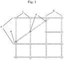
- Fig. 1 is a side view of an exemplary embodiment of a scaffolding system, which includes, for example, horizontally extending scaffolding tubes a and vertically extending scaffolding tubes b which are connected by means of scaffolding couplers in the form of cross couplers c.
- scaffolding tubes d are represented which are coupled diagonally to the scaffolding system.
- Theses tubes d are connected to other tubes (for example, vertical or horizontal tubes) by swivel couplers e.
- swivel couplers e for example, vertical or horizontal tubes.
- Figs. 2 , 3 and 4 show a scaffolding coupler of the scaffolding system represented in Fig. 1 .
- the coupler serves for detachably connecting scaffolding tubes which are oriented at right angles to each other (also called a cross coupler).
- the scaffolding coupler is formed by a first tube receiving part 1a and a second tube receiving part 1b.
- Each tube receiving part 1a is built up from steel, substantially U-shaped profiles 2a, 2b.
- a steel substantially U-shaped profile consists of five sections, viz., a base, two (oppositely extending) side legs which are preferably at right angles to the base, and two end parts/ends which are bent over, at right angles to the side legs or not so.
- the side legs and base part mentioned can for instance be substantially straight profile sections, but this is not requisite. Use of slightly bent sections is an option too.
- a substantially U-shaped profile as mentioned can for instance comprise fewer than the five sections mentioned, for instance when one or two end parts as mentioned are absent.
- each substantially U-shaped profile consists of oval-shaped wire, in particular steel wire.
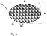
- the term 'oval-shaped wire' may be understood to mean a wire element having a substantially oval cross section (see Fig. 4 ), where for instance a thickness D1 measured in a first direction (along a first main axis, the long axis, of the oval) deviates considerably from a thickness D2 in a second direction (for instance along a second main axis, the short axis, of the oval), normal to the first direction.
- the oval mentioned can be, for example, an ellipse, with two axes of symmetry X1, X2 (as in Fig. 4 ) extending normal to each other.
- a thickness ratio D1:D2 may for example be in the range of 4-1.5, in particular 3-1.5, or another range. According to a preferred embodiment, D1:D2 is in the range of 13:8-15:8; the ratio D1:D2 can be, e.g., 14:8.
- the thickness in the first direction D1 is greater than 13 mm, for example a thickness of 14 mm or 15 mm.
- the thickness in the second direction D2 is less than 11 mm and greater than 5 mm, for example, a thickness D2 of 8 mm or 7 mm.
- the thickness in the first direction D1 is 14 mm and the thickness in the second direction D2 is 8 mm.
- the substantially U-shaped profile can for instance be formed by bending wire having an oval-shaped cross section as mentioned, with bending axes being parallel to the short axis X2 of the oval.
- the neighboring sections of a substantially U-shaped profile are, conversely, mutually bent over in a bending plane which is parallel to a short main axis X2 of the oval.
- bending over can be carried out using relatively little force with respect to bending in the earlier- mentioned direction, i.e., in the plane parallel to the long main axis X1.
- the first tube receiving part 1a and the second tube receiving part 1b are bonded together by means of a welded connection, whereby the inner side of the bases of two steel, substantially U-shaped profiles 2a, 2b of a tube receiving part 1a are welded to the inner side of the bases of the two steel, substantially U-shaped profiles 2c, 2d of the other tube receiving part 1b.
- the tube insert openings of the first tube receiving part 1a and the second tube receiving part 1b face away from each other.
- connection is such that - viewed in cross section - long main axes X1 of the two base sections (bases) of the one tube receiving part 1a touch long main axes of the bases of the other tube receiving part 1b.
- connection is such that - viewed in cross section - short main axes X2 of the bases of the one tube receiving part 1a run substantially parallel to the short main axes X2 of the bases of the other tube receiving part 1b, and at a distance from each other. In this manner, an especially durable connection can be achieved, in particular when welding the bases together.
- the bases of the first tube receiving part 1a and the bases of the second tube receiving part are to some extent sunk into each other/fused together, via mutually facing end faces.
- the two steel, substantially U-shaped profiles 2a, 2b of a receiving part 1a define a part of the tube clamping space, which is closable with a hingeable closing element 3a.
- the closing element 3a is hingeable from a release position to the tube clamping position about a hinge axis 6a.
- the hinge axis 6a is for instance non-detachably connected to the tube receiving part 1a, more specifically at right angles to the bent-over parts of the steel substantially U-shaped profiles 2a, 2b, and consists of oval-shaped wire.
- the closing element 3a is fixable in the tube clamping position with a wedge 4a, which is non-detachably connected to the closing element 3a by means of a connection 5a of oval-shaped wire.
- Figs. 5 and 6 show an alternative embodiment, viz., a scaffolding coupler for detachably connecting, for example, horizontally or vertically oriented scaffolding tubes to scaffolding tubes that are diagonally oriented. Tubes B being engaged are drawn-in in Fig. 6 .
- the scaffolding coupler is formed by a first tube receiving part 1a and a second tube receiving part 1b.
- each tube receiving part 1a is built up from steel, substantially U-shaped profiles 2a, 2b.
- a steel, substantially U-shaped profile consists of five parts: a base, two side legs which are preferably at right angles to the base, and two ends which are bent over, preferably at right angles to the side legs.
- the profile preferably consists of oval-shaped wire, which is bent into the substantially U-shaped form.
- the first tube receiving part 1a and the second tube receiving part 1b are connected to each other by a rotatable connection R (for instance, comprising two revolving discs rotatably coupled to each other), with the openings of the tube receiving parts 1a, 1b facing away from each other.
- a rotational axis of the rotatable connection extends in particular at right angles to the bases of the substantially U-shaped profiles, which will be clear to those skilled in the art.
- the bases of the tube receiving parts are fixedly welded to revolving plates/flanges of the rotatable connection.
- the tube insert openings of the first tube receiving part 1a and the second tube receiving part 1b face away from each other.
- the two steel, substantially U-shaped profiles 2a, 2b of a receiving part 1a define a part of the tube clamping space, which is closable by a hingeable closing element 3a.
- the closing element 3a is hingeable from a release position to the tube clamping position about a hinge axis 6a.
- the hinge axis 6a is for instance non-detachably connected to the tube receiving part 1a, more specifically at right angles to the bent-over parts of the steel, substantially U-shaped profiles 2a, 2b.
- the hinge axis 6a consists, for example, of wire having a substantially circular cross section.
- a method for forming the wire mentioned can utilize, for example, wire rolling or wire drawing, whereby a steel base wire (for instance, having a circular cross section) is deformed.
- the oval-shaped wire can for instance be formed by deformation of steel wire of initially circular cross section, having, for example, a thickness (outer diameter) in the range of 12-15 mm, in particular an outer diameter of 14 mm.
- Wire of this kind has been found to be suitably workable, in particular bendable, to form the substantially U-shaped profiles therefrom.
- the scaffolding coupler formed with these substantially U-shaped profiles is strong and durable, and thus safe and reliable in use.
- the steel wire is preferably galvanized for the purpose of reducing or preventing corrosion.
- Galvanizing is preferably carried out after formation of the oval cross section.
Landscapes
- Engineering & Computer Science (AREA)
- Architecture (AREA)
- Mechanical Engineering (AREA)
- Civil Engineering (AREA)
- Structural Engineering (AREA)
- Mutual Connection Of Rods And Tubes (AREA)
Claims (15)
- Gerüstkoppler zum lösbaren Verbinden von Gerüstrohren eines Gerüstsystems aneinander, wobei der Gerüstkoppler zwei Rohraufnahmeteile (1a, 1b) umfasst, dadurch gekennzeichnet, dass ein oder mehr Teile des Gerüstkopplers im Wesentlichen aus ovalförmigem Draht bestehen.
- Gerüstkoppler nach Anspruch 1, dadurch gekennzeichnet, dass mindestens eines der Röhren aufnehmenden Teile (1a) von mindestens zwei im Wesentlichen U-förmigen Stahlprofilen (2a, 2b) gebildet wird.
- Gerüstkoppler nach Anspruch 2, dadurch gekennzeichnet, dass eines oder mehrere der im Wesentlichen U-förmigen Profile (2a, 2b, 2c, 2d) aus ovalförmigem Draht besteht.
- Gerüstkoppler nach Anspruch 3, dadurch gekennzeichnet, dass eines oder mehrere der im Wesentlichen U-förmigen Profile (2a, 2b, 2c, 2d) aus ovalförmigem Draht besteht.
- Gerüstkoppler nach einem der vorhergehenden Ansprüche 2-4, dadurch gekennzeichnet, dass die im Wesentlichen U-förmigen Profile (2a, 2b) mindestens einen Teil eines Rohrklemmraums definieren, von dem eine Rohreinsetzöffnung durch mindestens ein Verschließelement (3a, 3b) verschließbar ist.
- Gerüstkoppler nach einem der vorhergehenden Ansprüche, wobei die Rohraufnahmeteile (1a, 1b) drehbar verbunden sind.
- Gerüstkoppler nach einem der vorhergehenden Ansprüche, dadurch gekennzeichnet, dass der ovalförmige Draht eine Dicke hat, die im Bereich von 6-20 mm ist.
- Gerüstkoppler nach einem der vorhergehenden Ansprüche, dadurch gekennzeichnet, dass die ovale Form eine lange Achse (X1) definiert, wobei eine Dicke D1 des Drahtes, gemessen entlang der langen Achse (X1), größer als 12 mm ist.
- Gerüstkoppler nach Anspruch 8, wobei die Dicke D1, gemessen entlang der langen Achse (X1) größer als 14 oder 15 mm ist.
- Gerüstkoppler nach einem der vorhergehenden Ansprüche, dadurch gekennzeichnet, dass die ovale Form eine kurze Achse (X2) definiert, wobei eine Dicke D2 des Drahtes, gemessen entlang der kurzen Achse (X2), kleiner als 11 mm und größter als 5 mm ist.
- Gerüstkoppler nach Anspruch 10, wobei die Dicke D2, gemessen entlang der kurzen Achse (X2), 7 oder 8 mm ist.
- Gerüstkopplersystem, umfassend Gerüstrohre sowie mindesten einen Gerüstkoppler nach einem der vorhergehenden Ansprüche zum lösbaren Verbinden der Gerüstrohre aneinander.
- Verfahren zur Herstellung eines Gerüstkopplers nach einem der Ansprüche 1-11, wobei ovalförmiger Draht bereitgestellt wird, aus dem mindestens ein Teil des Kopplers geformt wird.
- Verfahren nach Anspruch 13, wobei der ovalförmige Draht durch Ziehen von Basisdraht, der insbesondere einen kreisförmigen Querschnitt hat, zu einer ovalen Form geformt wird.
- Verfahren nach Anspruch 13, wobei der ovalförmige Draht durch Walzen von Basisdraht, der insbesondere einen kreisförmigen Querschnitt hat, zu einer ovalen Form hergestellt wird.
Applications Claiming Priority (2)
| Application Number | Priority Date | Filing Date | Title |
|---|---|---|---|
| NL2013802A NL2013802B1 (nl) | 2014-11-14 | 2014-11-14 | Steigersysteem, alsmede een koppeling van een dergelijk systeem en een werkwijze voor de vervaardiging van de koppeling. |
| PCT/NL2015/050797 WO2016076723A1 (en) | 2014-11-14 | 2015-11-13 | Scaffolding system, as well as a coupler of such system and a method for the manufacture of the coupler |
Publications (2)
| Publication Number | Publication Date |
|---|---|
| EP3218558A1 EP3218558A1 (de) | 2017-09-20 |
| EP3218558B1 true EP3218558B1 (de) | 2018-08-15 |
Family
ID=52355152
Family Applications (1)
| Application Number | Title | Priority Date | Filing Date |
|---|---|---|---|
| EP15830888.2A Active EP3218558B1 (de) | 2014-11-14 | 2015-11-13 | Gerüstsystem, sowie koppler eines derartigen systems und verfahren zur herstellung des kopplers |
Country Status (5)
| Country | Link |
|---|---|
| EP (1) | EP3218558B1 (de) |
| AU (1) | AU2015347374B2 (de) |
| CA (1) | CA2967795C (de) |
| NL (1) | NL2013802B1 (de) |
| WO (1) | WO2016076723A1 (de) |
Family Cites Families (5)
| Publication number | Priority date | Publication date | Assignee | Title |
|---|---|---|---|---|
| CA210275A (en) * | 1921-04-12 | Allister Currie John | Fencing | |
| NL75356C (de) | ||||
| BE792696A (nl) | 1971-12-15 | 1973-06-13 | Mulder Rudolf | Werkwijze voor het tot een kruisstukvormige steigerklem verbinden van twee opneemdelen en kruisstuk verkregen met toepassing van die werkwijz |
| NL7811721A (nl) | 1978-11-29 | 1980-06-02 | Mulder Rudolf | Steigerklem met wighouder. |
| NL1021361C2 (nl) * | 2002-08-30 | 2004-03-02 | Zwatec B V | Steigerpijpklem. |
-
2014
- 2014-11-14 NL NL2013802A patent/NL2013802B1/nl not_active IP Right Cessation
-
2015
- 2015-11-13 CA CA2967795A patent/CA2967795C/en active Active
- 2015-11-13 AU AU2015347374A patent/AU2015347374B2/en not_active Ceased
- 2015-11-13 EP EP15830888.2A patent/EP3218558B1/de active Active
- 2015-11-13 WO PCT/NL2015/050797 patent/WO2016076723A1/en not_active Ceased
Non-Patent Citations (1)
| Title |
|---|
| None * |
Also Published As
| Publication number | Publication date |
|---|---|
| AU2015347374A1 (en) | 2017-06-15 |
| EP3218558A1 (de) | 2017-09-20 |
| CA2967795A1 (en) | 2016-05-19 |
| NL2013802B1 (nl) | 2016-10-10 |
| WO2016076723A1 (en) | 2016-05-19 |
| CA2967795C (en) | 2023-06-13 |
| AU2015347374B2 (en) | 2020-07-02 |
Similar Documents
| Publication | Publication Date | Title |
|---|---|---|
| KR101512946B1 (ko) | 라운드 앵글 및 철근을 이용한 선조립 기둥 | |
| CN101646864A (zh) | 用于风力涡轮机的塔架 | |
| KR100937678B1 (ko) | 벽 거푸집 유닛 및 벽 거푸집 구조체 | |
| CN105569185A (zh) | 高强度凹凸槽型钢连接房屋 | |
| CN102312481A (zh) | 钢筋砼预制构件 | |
| US20190338520A1 (en) | Truss system and reinforcement | |
| CN110469043A (zh) | 一种由交叉折弯型隔板连接的钢板组合剪力墙及制备方法 | |
| CN210316020U (zh) | 一种型钢混凝土组合结构 | |
| EP3218558B1 (de) | Gerüstsystem, sowie koppler eines derartigen systems und verfahren zur herstellung des kopplers | |
| JP2016044538A (ja) | 連結固定ブリッジ部材 | |
| AU2005295769A1 (en) | Building panel and building structure | |
| WO2006085185A1 (en) | Rolled metal section; posts and frame members made from same; and assembly fittings | |
| AU2010242553A1 (en) | Construction element | |
| EP3816361A1 (de) | Verfahren zur herstellung eines rohrförmigen stützelements und dasselbe umfassender gittermast | |
| CN104264976B (zh) | 一种可移动式脚手架碗扣式扣件及其操作方法 | |
| US9121170B2 (en) | Framework for structural use | |
| CN211037820U (zh) | 一种钢筋混凝土梁设备洞口的加强结构 | |
| CN206245598U (zh) | 核心约束型空腹式型钢混凝土组合柱 | |
| CN211342082U (zh) | 一种用于建筑施工管理的围栏 | |
| CN211572254U (zh) | 一种易拆装箍筋 | |
| KR200311247Y1 (ko) | 조립식 초경량빔 | |
| KR100492719B1 (ko) | 건축용 조립식 동바리 | |
| EP2801673A1 (de) | Mörtellinienverstärkung zur festigung von backstein- oder blockwänden | |
| JP2018112021A (ja) | 切梁火打接続構造および切梁火打接続ピース | |
| CN207063264U (zh) | 钢结构秸秆材质板复合楼承板构件 |
Legal Events
| Date | Code | Title | Description |
|---|---|---|---|
| PUAI | Public reference made under article 153(3) epc to a published international application that has entered the european phase |
Free format text: ORIGINAL CODE: 0009012 |
|
| 17P | Request for examination filed |
Effective date: 20170614 |
|
| AK | Designated contracting states |
Kind code of ref document: A1 Designated state(s): AL AT BE BG CH CY CZ DE DK EE ES FI FR GB GR HR HU IE IS IT LI LT LU LV MC MK MT NL NO PL PT RO RS SE SI SK SM TR |
|
| AX | Request for extension of the european patent |
Extension state: BA ME |
|
| DAV | Request for validation of the european patent (deleted) | ||
| DAX | Request for extension of the european patent (deleted) | ||
| RIC1 | Information provided on ipc code assigned before grant |
Ipc: E04G 7/14 20060101AFI20180302BHEP Ipc: E04G 7/16 20060101ALI20180302BHEP |
|
| GRAP | Despatch of communication of intention to grant a patent |
Free format text: ORIGINAL CODE: EPIDOSNIGR1 |
|
| INTG | Intention to grant announced |
Effective date: 20180420 |
|
| GRAS | Grant fee paid |
Free format text: ORIGINAL CODE: EPIDOSNIGR3 |
|
| GRAA | (expected) grant |
Free format text: ORIGINAL CODE: 0009210 |
|
| AK | Designated contracting states |
Kind code of ref document: B1 Designated state(s): AL AT BE BG CH CY CZ DE DK EE ES FI FR GB GR HR HU IE IS IT LI LT LU LV MC MK MT NL NO PL PT RO RS SE SI SK SM TR |
|
| REG | Reference to a national code |
Ref country code: CH Ref legal event code: EP Ref country code: GB Ref legal event code: FG4D Ref country code: AT Ref legal event code: REF Ref document number: 1029938 Country of ref document: AT Kind code of ref document: T Effective date: 20180815 |
|
| REG | Reference to a national code |
Ref country code: IE Ref legal event code: FG4D |
|
| REG | Reference to a national code |
Ref country code: DE Ref legal event code: R096 Ref document number: 602015014963 Country of ref document: DE |
|
| REG | Reference to a national code |
Ref country code: NL Ref legal event code: FP |
|
| REG | Reference to a national code |
Ref country code: LT Ref legal event code: MG4D |
|
| REG | Reference to a national code |
Ref country code: AT Ref legal event code: MK05 Ref document number: 1029938 Country of ref document: AT Kind code of ref document: T Effective date: 20180815 |
|
| PG25 | Lapsed in a contracting state [announced via postgrant information from national office to epo] |
Ref country code: FI Free format text: LAPSE BECAUSE OF FAILURE TO SUBMIT A TRANSLATION OF THE DESCRIPTION OR TO PAY THE FEE WITHIN THE PRESCRIBED TIME-LIMIT Effective date: 20180815 Ref country code: NO Free format text: LAPSE BECAUSE OF FAILURE TO SUBMIT A TRANSLATION OF THE DESCRIPTION OR TO PAY THE FEE WITHIN THE PRESCRIBED TIME-LIMIT Effective date: 20181115 Ref country code: GR Free format text: LAPSE BECAUSE OF FAILURE TO SUBMIT A TRANSLATION OF THE DESCRIPTION OR TO PAY THE FEE WITHIN THE PRESCRIBED TIME-LIMIT Effective date: 20181116 Ref country code: RS Free format text: LAPSE BECAUSE OF FAILURE TO SUBMIT A TRANSLATION OF THE DESCRIPTION OR TO PAY THE FEE WITHIN THE PRESCRIBED TIME-LIMIT Effective date: 20180815 Ref country code: IS Free format text: LAPSE BECAUSE OF FAILURE TO SUBMIT A TRANSLATION OF THE DESCRIPTION OR TO PAY THE FEE WITHIN THE PRESCRIBED TIME-LIMIT Effective date: 20181215 Ref country code: AT Free format text: LAPSE BECAUSE OF FAILURE TO SUBMIT A TRANSLATION OF THE DESCRIPTION OR TO PAY THE FEE WITHIN THE PRESCRIBED TIME-LIMIT Effective date: 20180815 Ref country code: SE Free format text: LAPSE BECAUSE OF FAILURE TO SUBMIT A TRANSLATION OF THE DESCRIPTION OR TO PAY THE FEE WITHIN THE PRESCRIBED TIME-LIMIT Effective date: 20180815 Ref country code: BG Free format text: LAPSE BECAUSE OF FAILURE TO SUBMIT A TRANSLATION OF THE DESCRIPTION OR TO PAY THE FEE WITHIN THE PRESCRIBED TIME-LIMIT Effective date: 20181115 Ref country code: LT Free format text: LAPSE BECAUSE OF FAILURE TO SUBMIT A TRANSLATION OF THE DESCRIPTION OR TO PAY THE FEE WITHIN THE PRESCRIBED TIME-LIMIT Effective date: 20180815 |
|
| PG25 | Lapsed in a contracting state [announced via postgrant information from national office to epo] |
Ref country code: AL Free format text: LAPSE BECAUSE OF FAILURE TO SUBMIT A TRANSLATION OF THE DESCRIPTION OR TO PAY THE FEE WITHIN THE PRESCRIBED TIME-LIMIT Effective date: 20180815 Ref country code: LV Free format text: LAPSE BECAUSE OF FAILURE TO SUBMIT A TRANSLATION OF THE DESCRIPTION OR TO PAY THE FEE WITHIN THE PRESCRIBED TIME-LIMIT Effective date: 20180815 Ref country code: HR Free format text: LAPSE BECAUSE OF FAILURE TO SUBMIT A TRANSLATION OF THE DESCRIPTION OR TO PAY THE FEE WITHIN THE PRESCRIBED TIME-LIMIT Effective date: 20180815 |
|
| PGFP | Annual fee paid to national office [announced via postgrant information from national office to epo] |
Ref country code: TR Payment date: 20181011 Year of fee payment: 13 |
|
| PG25 | Lapsed in a contracting state [announced via postgrant information from national office to epo] |
Ref country code: ES Free format text: LAPSE BECAUSE OF FAILURE TO SUBMIT A TRANSLATION OF THE DESCRIPTION OR TO PAY THE FEE WITHIN THE PRESCRIBED TIME-LIMIT Effective date: 20180815 Ref country code: PL Free format text: LAPSE BECAUSE OF FAILURE TO SUBMIT A TRANSLATION OF THE DESCRIPTION OR TO PAY THE FEE WITHIN THE PRESCRIBED TIME-LIMIT Effective date: 20180815 Ref country code: RO Free format text: LAPSE BECAUSE OF FAILURE TO SUBMIT A TRANSLATION OF THE DESCRIPTION OR TO PAY THE FEE WITHIN THE PRESCRIBED TIME-LIMIT Effective date: 20180815 Ref country code: CZ Free format text: LAPSE BECAUSE OF FAILURE TO SUBMIT A TRANSLATION OF THE DESCRIPTION OR TO PAY THE FEE WITHIN THE PRESCRIBED TIME-LIMIT Effective date: 20180815 Ref country code: EE Free format text: LAPSE BECAUSE OF FAILURE TO SUBMIT A TRANSLATION OF THE DESCRIPTION OR TO PAY THE FEE WITHIN THE PRESCRIBED TIME-LIMIT Effective date: 20180815 Ref country code: IT Free format text: LAPSE BECAUSE OF FAILURE TO SUBMIT A TRANSLATION OF THE DESCRIPTION OR TO PAY THE FEE WITHIN THE PRESCRIBED TIME-LIMIT Effective date: 20180815 |
|
| REG | Reference to a national code |
Ref country code: DE Ref legal event code: R097 Ref document number: 602015014963 Country of ref document: DE |
|
| PG25 | Lapsed in a contracting state [announced via postgrant information from national office to epo] |
Ref country code: DK Free format text: LAPSE BECAUSE OF FAILURE TO SUBMIT A TRANSLATION OF THE DESCRIPTION OR TO PAY THE FEE WITHIN THE PRESCRIBED TIME-LIMIT Effective date: 20180815 Ref country code: SM Free format text: LAPSE BECAUSE OF FAILURE TO SUBMIT A TRANSLATION OF THE DESCRIPTION OR TO PAY THE FEE WITHIN THE PRESCRIBED TIME-LIMIT Effective date: 20180815 Ref country code: SK Free format text: LAPSE BECAUSE OF FAILURE TO SUBMIT A TRANSLATION OF THE DESCRIPTION OR TO PAY THE FEE WITHIN THE PRESCRIBED TIME-LIMIT Effective date: 20180815 |
|
| PLBE | No opposition filed within time limit |
Free format text: ORIGINAL CODE: 0009261 |
|
| STAA | Information on the status of an ep patent application or granted ep patent |
Free format text: STATUS: NO OPPOSITION FILED WITHIN TIME LIMIT |
|
| REG | Reference to a national code |
Ref country code: CH Ref legal event code: PL |
|
| 26N | No opposition filed |
Effective date: 20190516 |
|
| PG25 | Lapsed in a contracting state [announced via postgrant information from national office to epo] |
Ref country code: MC Free format text: LAPSE BECAUSE OF FAILURE TO SUBMIT A TRANSLATION OF THE DESCRIPTION OR TO PAY THE FEE WITHIN THE PRESCRIBED TIME-LIMIT Effective date: 20180815 Ref country code: LU Free format text: LAPSE BECAUSE OF NON-PAYMENT OF DUE FEES Effective date: 20181113 |
|
| REG | Reference to a national code |
Ref country code: IE Ref legal event code: MM4A |
|
| PG25 | Lapsed in a contracting state [announced via postgrant information from national office to epo] |
Ref country code: CH Free format text: LAPSE BECAUSE OF NON-PAYMENT OF DUE FEES Effective date: 20181130 Ref country code: SI Free format text: LAPSE BECAUSE OF FAILURE TO SUBMIT A TRANSLATION OF THE DESCRIPTION OR TO PAY THE FEE WITHIN THE PRESCRIBED TIME-LIMIT Effective date: 20180815 Ref country code: LI Free format text: LAPSE BECAUSE OF NON-PAYMENT OF DUE FEES Effective date: 20181130 |
|
| PG25 | Lapsed in a contracting state [announced via postgrant information from national office to epo] |
Ref country code: FR Free format text: LAPSE BECAUSE OF NON-PAYMENT OF DUE FEES Effective date: 20181130 Ref country code: IE Free format text: LAPSE BECAUSE OF NON-PAYMENT OF DUE FEES Effective date: 20181113 |
|
| PG25 | Lapsed in a contracting state [announced via postgrant information from national office to epo] |
Ref country code: MT Free format text: LAPSE BECAUSE OF NON-PAYMENT OF DUE FEES Effective date: 20181113 |
|
| PG25 | Lapsed in a contracting state [announced via postgrant information from national office to epo] |
Ref country code: PT Free format text: LAPSE BECAUSE OF FAILURE TO SUBMIT A TRANSLATION OF THE DESCRIPTION OR TO PAY THE FEE WITHIN THE PRESCRIBED TIME-LIMIT Effective date: 20180815 |
|
| PG25 | Lapsed in a contracting state [announced via postgrant information from national office to epo] |
Ref country code: CY Free format text: LAPSE BECAUSE OF FAILURE TO SUBMIT A TRANSLATION OF THE DESCRIPTION OR TO PAY THE FEE WITHIN THE PRESCRIBED TIME-LIMIT Effective date: 20180815 Ref country code: MK Free format text: LAPSE BECAUSE OF NON-PAYMENT OF DUE FEES Effective date: 20180815 Ref country code: HU Free format text: LAPSE BECAUSE OF FAILURE TO SUBMIT A TRANSLATION OF THE DESCRIPTION OR TO PAY THE FEE WITHIN THE PRESCRIBED TIME-LIMIT; INVALID AB INITIO Effective date: 20151113 |
|
| PGFP | Annual fee paid to national office [announced via postgrant information from national office to epo] |
Ref country code: BE Payment date: 20220321 Year of fee payment: 7 |
|
| PG25 | Lapsed in a contracting state [announced via postgrant information from national office to epo] |
Ref country code: TR Free format text: LAPSE BECAUSE OF NON-PAYMENT OF DUE FEES Effective date: 20191113 |
|
| P01 | Opt-out of the competence of the unified patent court (upc) registered |
Effective date: 20230508 |
|
| REG | Reference to a national code |
Ref country code: BE Ref legal event code: MM Effective date: 20221130 |
|
| PG25 | Lapsed in a contracting state [announced via postgrant information from national office to epo] |
Ref country code: BE Free format text: LAPSE BECAUSE OF NON-PAYMENT OF DUE FEES Effective date: 20221130 |
|
| PGFP | Annual fee paid to national office [announced via postgrant information from national office to epo] |
Ref country code: GB Payment date: 20231123 Year of fee payment: 9 |
|
| PGFP | Annual fee paid to national office [announced via postgrant information from national office to epo] |
Ref country code: DE Payment date: 20231121 Year of fee payment: 9 |
|
| REG | Reference to a national code |
Ref country code: NL Ref legal event code: PD Owner name: PRM HOLDING B.V.; NL Free format text: DETAILS ASSIGNMENT: CHANGE OF OWNER(S), ASSIGNMENT; FORMER OWNER NAME: VAN THIEL UNITED B.V. Effective date: 20250123 |
|
| REG | Reference to a national code |
Ref country code: DE Ref legal event code: R119 Ref document number: 602015014963 Country of ref document: DE |
|
| GBPC | Gb: european patent ceased through non-payment of renewal fee |
Effective date: 20241113 |
|
| PG25 | Lapsed in a contracting state [announced via postgrant information from national office to epo] |
Ref country code: DE Free format text: LAPSE BECAUSE OF NON-PAYMENT OF DUE FEES Effective date: 20250603 |
|
| PG25 | Lapsed in a contracting state [announced via postgrant information from national office to epo] |
Ref country code: GB Free format text: LAPSE BECAUSE OF NON-PAYMENT OF DUE FEES Effective date: 20241113 |
|
| PGFP | Annual fee paid to national office [announced via postgrant information from national office to epo] |
Ref country code: NL Payment date: 20251119 Year of fee payment: 11 |