EP3219372A2 - Préfiltre avec un noyau de filtre détachable pour une alimentation en eau sans coupure - Google Patents
Préfiltre avec un noyau de filtre détachable pour une alimentation en eau sans coupure Download PDFInfo
- Publication number
- EP3219372A2 EP3219372A2 EP17158013.7A EP17158013A EP3219372A2 EP 3219372 A2 EP3219372 A2 EP 3219372A2 EP 17158013 A EP17158013 A EP 17158013A EP 3219372 A2 EP3219372 A2 EP 3219372A2
- Authority
- EP
- European Patent Office
- Prior art keywords
- filter
- recess
- water
- outlet
- inlet
- Prior art date
- Legal status (The legal status is an assumption and is not a legal conclusion. Google has not performed a legal analysis and makes no representation as to the accuracy of the status listed.)
- Withdrawn
Links
- XLYOFNOQVPJJNP-UHFFFAOYSA-N water Substances O XLYOFNOQVPJJNP-UHFFFAOYSA-N 0.000 title claims abstract description 118
- 238000011045 prefiltration Methods 0.000 title claims abstract description 47
- 238000001914 filtration Methods 0.000 claims abstract description 30
- 239000012535 impurity Substances 0.000 claims abstract description 12
- 230000002093 peripheral effect Effects 0.000 claims description 12
- 239000002351 wastewater Substances 0.000 claims description 8
- 238000004065 wastewater treatment Methods 0.000 claims description 5
- 239000013049 sediment Substances 0.000 abstract description 9
- 238000004140 cleaning Methods 0.000 description 7
- 241000195493 Cryptophyta Species 0.000 description 1
- JEIPFZHSYJVQDO-UHFFFAOYSA-N iron(III) oxide Inorganic materials O=[Fe]O[Fe]=O JEIPFZHSYJVQDO-UHFFFAOYSA-N 0.000 description 1
- 239000008400 supply water Substances 0.000 description 1
- 230000008685 targeting Effects 0.000 description 1
- 238000005406 washing Methods 0.000 description 1
Images




Classifications
-
- B—PERFORMING OPERATIONS; TRANSPORTING
- B01—PHYSICAL OR CHEMICAL PROCESSES OR APPARATUS IN GENERAL
- B01D—SEPARATION
- B01D29/00—Filters with filtering elements stationary during filtration, e.g. pressure or suction filters, not covered by groups B01D24/00 - B01D27/00; Filtering elements therefor
- B01D29/11—Filters with filtering elements stationary during filtration, e.g. pressure or suction filters, not covered by groups B01D24/00 - B01D27/00; Filtering elements therefor with bag, cage, hose, tube, sleeve or like filtering elements
- B01D29/13—Supported filter elements
- B01D29/15—Supported filter elements arranged for inward flow filtration
-
- B—PERFORMING OPERATIONS; TRANSPORTING
- B01—PHYSICAL OR CHEMICAL PROCESSES OR APPARATUS IN GENERAL
- B01D—SEPARATION
- B01D29/00—Filters with filtering elements stationary during filtration, e.g. pressure or suction filters, not covered by groups B01D24/00 - B01D27/00; Filtering elements therefor
- B01D29/11—Filters with filtering elements stationary during filtration, e.g. pressure or suction filters, not covered by groups B01D24/00 - B01D27/00; Filtering elements therefor with bag, cage, hose, tube, sleeve or like filtering elements
- B01D29/114—Filters with filtering elements stationary during filtration, e.g. pressure or suction filters, not covered by groups B01D24/00 - B01D27/00; Filtering elements therefor with bag, cage, hose, tube, sleeve or like filtering elements arranged for inward flow filtration
-
- B—PERFORMING OPERATIONS; TRANSPORTING
- B01—PHYSICAL OR CHEMICAL PROCESSES OR APPARATUS IN GENERAL
- B01D—SEPARATION
- B01D29/00—Filters with filtering elements stationary during filtration, e.g. pressure or suction filters, not covered by groups B01D24/00 - B01D27/00; Filtering elements therefor
- B01D29/11—Filters with filtering elements stationary during filtration, e.g. pressure or suction filters, not covered by groups B01D24/00 - B01D27/00; Filtering elements therefor with bag, cage, hose, tube, sleeve or like filtering elements
- B01D29/31—Self-supporting filtering elements
- B01D29/33—Self-supporting filtering elements arranged for inward flow filtration
-
- B—PERFORMING OPERATIONS; TRANSPORTING
- B01—PHYSICAL OR CHEMICAL PROCESSES OR APPARATUS IN GENERAL
- B01D—SEPARATION
- B01D29/00—Filters with filtering elements stationary during filtration, e.g. pressure or suction filters, not covered by groups B01D24/00 - B01D27/00; Filtering elements therefor
- B01D29/88—Filters with filtering elements stationary during filtration, e.g. pressure or suction filters, not covered by groups B01D24/00 - B01D27/00; Filtering elements therefor having feed or discharge devices
- B01D29/90—Filters with filtering elements stationary during filtration, e.g. pressure or suction filters, not covered by groups B01D24/00 - B01D27/00; Filtering elements therefor having feed or discharge devices for feeding
- B01D29/906—Special treatment of the feed stream before contacting the filtering element, e.g. cutting
-
- B—PERFORMING OPERATIONS; TRANSPORTING
- B01—PHYSICAL OR CHEMICAL PROCESSES OR APPARATUS IN GENERAL
- B01D—SEPARATION
- B01D29/00—Filters with filtering elements stationary during filtration, e.g. pressure or suction filters, not covered by groups B01D24/00 - B01D27/00; Filtering elements therefor
- B01D29/96—Filters with filtering elements stationary during filtration, e.g. pressure or suction filters, not covered by groups B01D24/00 - B01D27/00; Filtering elements therefor in which the filtering elements are moved between filtering operations; Particular measures for removing or replacing the filtering elements; Transport systems for filters
-
- B—PERFORMING OPERATIONS; TRANSPORTING
- B01—PHYSICAL OR CHEMICAL PROCESSES OR APPARATUS IN GENERAL
- B01D—SEPARATION
- B01D35/00—Filtering devices having features not specifically covered by groups B01D24/00 - B01D33/00, or for applications not specifically covered by groups B01D24/00 - B01D33/00; Auxiliary devices for filtration; Filter housing constructions
- B01D35/14—Safety devices specially adapted for filtration; Devices for indicating clogging
- B01D35/147—Bypass or safety valves
-
- B—PERFORMING OPERATIONS; TRANSPORTING
- B01—PHYSICAL OR CHEMICAL PROCESSES OR APPARATUS IN GENERAL
- B01D—SEPARATION
- B01D2201/00—Details relating to filtering apparatus
- B01D2201/29—Filter cartridge constructions
- B01D2201/291—End caps
-
- B—PERFORMING OPERATIONS; TRANSPORTING
- B01—PHYSICAL OR CHEMICAL PROCESSES OR APPARATUS IN GENERAL
- B01D—SEPARATION
- B01D2201/00—Details relating to filtering apparatus
- B01D2201/30—Filter housing constructions
- B01D2201/301—Details of removable closures, lids, caps, filter heads
- B01D2201/302—Details of removable closures, lids, caps, filter heads having inlet or outlet ports
-
- B—PERFORMING OPERATIONS; TRANSPORTING
- B01—PHYSICAL OR CHEMICAL PROCESSES OR APPARATUS IN GENERAL
- B01D—SEPARATION
- B01D2201/00—Details relating to filtering apparatus
- B01D2201/32—Flow characteristics of the filter
Definitions
- the present invention relates to a water bypass device and, more particularly, to a pre-filter with a detachable filter core for un-interruptible water supply.
- An objective of the present invention is to provide a pre-filter with a detachable filter core for un-interruptible water supply targeting at providing a pre-filter with water supply un-interrupted by removal of the filter core as a result of cleaning or replacement.
- the pre-filter with a detachable filter core for un-interruptible water supply includes a valve seat, a filter canister and a switching mechanism.
- the valve seat includes an inlet port and an outlet port.
- the filter canister detachably attached to a bottom of the valve seat and has a chamber, a filtered water outlet and an inlet water chamber.
- the chamber is defined within the filter canister.
- the filtering tube is hollow and is mounted inside the chamber of the filter canister.
- the filtered water outlet is formed through a top end of the filtering tube.
- the inlet water chamber is defined between the inner wall of the chamber of the filter canister and a peripheral wall of the filtering tube.
- the switching mechanism is rotatably mounted into the valve seat.
- the switching mechanism is selectively switched to form a filtering position with the inlet port of the valve seat communicating with the inlet water chamber of the filter canister and the filtered water outlet of the filter canister communicating with the outlet port of the valve seat, and the switching mechanism is selectively switched to form a bypass position with the inlet port of the valve seat directly communicating with the outlet port of the valve seat.
- the pre-filter has the following advantages:
- the inlet port of the pre-filter is not required to be closed in the event of cleaning or replacement of the filter core, and all it needs is to switch to a bypass water flow path to continuously supply water without causing interruption in household water supply when the filter core is cleaned or replaced.
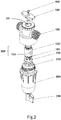
- a pre-filter with a detachable filter core for un-interruptible water supply in accordance with the present invention includes a valve seat 100, a filter canister 200 and a valve member 300.
- the valve member 300 is axially and rotatably mounted inside the valve seat 100, and a bottom portion of the valve member 300 is connected with the filter canister 200.
- the valve seat 100 is integrally formed and includes an inlet port 110, an outlet port 120, a central bore 111 and a knob 140.
- the inlet port 110 and the outlet port 120 are respectively formed in two lateral sides of the valve seat 100, and the inlet port 110 is opposite to the outlet port 120.
- the inlet port 110 and the outlet port 120 having threads on an interior surface thereof that engage threads on an outer surface of a pipe or similar conduit.
- the central bore 111 is centrally formed through the valve seat 100 and communicating with the inlet port 110 and the outlet port 120.
- the knob 140 is mounted in the valve seat 100 by a fastener, such as a screw 400.
- valve member 300 is mounted into the central bore 111 of the valve seat 100 and the knob 140 is securely connected to a top portion of the valve member 300 by the screw 400 and is rotatable with respect the valve seat 100 for the valve member 300 to be rotated by turning the knob 140.
- the filter canister 200 is detachably attached to a bottom of the valve seat 100, which removes sediment and other impurities from the water flowing through the filter canister 200, and includes a chamber, a filtering tube 210, a filtered water outlet 211, an inlet water chamber 220, a waste water outlet 230 and a waste water treatment valve 240.
- the chamber is defined within the filter canister 200.
- the filtering tube 210 is hollow and is mounted inside the chamber of the filter canister 200, which removes sediment and other impurities from the water based on physical filtration means to block larger impurities, such as dirt, rust, algae and the like.
- the filtered water outlet 211 is formed through a top end of the filtering tube 210.
- the inlet water chamber 220 is defined between an inner wall of the chamber of the filter canister 200 and a peripheral wall of the filtering tube 210.
- the waste water outlet 230 is formed through a bottom end of the filter canister 200, communicates with the inlet water chamber 220, and is connected with the waste water treatment valve 240, and water containing impurities flows out of the waste water treatment valve 240 through the waste water outlet 230.
- valve member 300 There are two embodiments associated with the pre-filter with a detachable filter core for un-interruptible water supply in accordance with the present invention and differences between the two embodiments reside in the structure of the valve member 300 as elaborated as follows.
- the valve member 300 in embodiment 1 includes a body 130, an inlet opening 131, an outlet opening 132, a first flow chamber 134, a second flow chamber 135 and an unfiltered water channel 133.
- a bottom portion of the body 130 is hollow and a top portion of the body 130 is mounted inside the bottom portion of the valve seat 100.
- the inlet opening 131 and the outlet opening 132 are oppositely formed through a peripheral wall of the bottom portion of the body 130.
- the unfiltered water channel 133 is laterally formed through the peripheral wall of the bottom portion of the body 130.
- the unfiltered water channel 133 is aligned in a direction intersected with that of each of the inlet opening 131 and the outlet opening 132 facing, and preferably, the angle included between the direction of each of the inlet opening 131, outlet opening 132 facing and the aligning direction of the unfiltered water channel 133 is 90°.
- the first flow chamber 134 is strip-shaped, and both ends of the first flow chamber 134 are respectively connected and communicate with the inlet opening 131 and the inlet water chamber 220 of the filter canister 200.
- the second flow chamber 135 communicates with the outlet opening 132 of the valve member 300 and the filtered water outlet 211 of the filter canister 200.
- Two collar seals 136 are respectively mounted around a portion above the inlet opening 131 and a portion below the outlet opening 132 to hermetically seal water permeating from the unfiltered water channel 133, the inlet opening 131 and the outlet opening 132 when aligned with the inlet port 110 and the outlet port 120.
- the knob 140 is turned to rotate the body 130 of the valve member 300 to a filtering position with the inlet opening 131 and the outlet opening 132 of the valve member 300 respectively aligned and communicating with the inlet port 110 and the outlet port 120 of the valve seat 100 to establish the first water flow path for water from the incoming water pipe to flow through the inlet port 110 of the valve seat 100 and the inlet opening 131 and the first flow chamber 134 into the inlet water chamber 220 of the filter canister 200.
- the sediment and other impurities in the water are screened out by the filtering tube 210 and water containing the sediment and impurities flows out through the waste water outlet 230.
- the filtered water passes through the filtering tube 210 and flows out of the outlet port 120 through the filter water outlet 211, the second flow chamber 135, the outlet opening 132 to supply the water-receiving equipment.
- the valve member 200 of the pre-filter overcomes the problem of water supply interrupted by detaching filter core for cleaning or replacement when the pre-filter is positioned at a bypass position.
- the knob 140 is turned to rotate the body 130 of the valve member 300 to the bypass position with both ends of the unfiltered water channel 133 respectively aligned and communicating with the inlet opening 131 and outlet opening 132 to establish the second water flow path for water from the incoming water pipe to flow in the pre-filter through the inlet port 110 and then flow out of the pre-filter through the unfiltered water channel 133 and outlet port 120.
- the pre-filter stays at the bypass position, unfiltered water continuously flows through the valve seat 100 without passing through the valve member 200 to a household or commercial environment without interruption even when the valve member 200 is detached for cleaning or replacement.
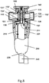
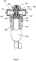
- valve member 300' in embodiment 2 includes a body 130', a moveable valve 150, a gasket 160 and a rotation shaft 170.
- the body 130' is mounted inside the valve seat (100) and includes an inlet opening 131', an outlet opening 132', a first flow chamber 134', a second flow chamber 135', a shaft bore 136 (with reference Fig. 8 ) and a gasket-receiving slot 137.
- the inlet opening 131' and the outlet opening 132' are respectively and oppositely formed through a peripheral wall of a bottom portion of the body 130'.
- the inlet opening 131' is connected and communicates with the inlet port 110.
- the outlet opening 132' is connected and communicates with the outlet port 120.
- first flow chamber 134' and the second flow chamber 135' are structurally similar to the first flow chamber 134 and the second flow chamber 135 of the foregoing embodiment, description of the first flows chamber 134' and the second flows chamber 135' is not repeated here.
- the shaft bore 135 is centrally formed through the body 130'.
- the gasket-receiving slot 137 is formed in a bottom of the body 130'.
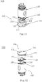
- the moveable valve 150 is mounted on the bottom of the body 130', and has an upper portion 155 and a lower portion 156.
- the upper portion 155 of the moveable valve 150 is rotatably mounted on a bottom of the body 130'.
- the moveable valve 150 has a first recess 151, a second recess 152, a third recess 153, a fourth recess 154 and a breach 157.
- the breach 157 is formed in a peripheral wall of the lower portion 156.
- the first recess 151 and the second recess 152 are oppositely formed through the upper potion 155, the first recess 151 is formed through the upper portion 155 and communicates with the breach 157 and the inlet water chamber 220 of the filter canister 200, and the second recess 152 is formed through the upper portion 155 and the lower portion 156 and communicates with the filtered water outlet 211 of the filter canister 200.
- the third recess 153 and the fourth recess 154 are formed in a top surface of the upper portion 155, are oppositely located between the first recess 151 and the second recess 152, and communicate with each other.
- the gasket 160 is received in the gas-receiving slot 137 to form hermetic seal between the body 130' and the moveable valve 150.
- the rotation shaft 170 is securely mounted through the shaft bore 136 of the body 130' (with reference Fig. 8 ). A bottom end of the rotation shaft 170 is mounted in the moveable valve 150, and a top end of the rotation shaft 170 is securely mounted in the knob 140 by a fastener such as a screw 400. Thus, when the knob 140 is turned, the movable valve 150 is rotatable with respect to the body 130'.
- the inlet port 110 and the outlet port 120 are respectively connected to an incoming water pipe and water-receiving equipment.
- the knob 140 is turned to rotate the movable valve 150 to a filtering position with the first recess 151 and the second recess 152 of the movable valve 150 respectively aligned and communicating with the first flow channel 134' and the second flow channel 135' of the body 130' to establish the first water flow path for water from the incoming water pipe to sequentially flows through the inlet port 110 of the valve seat 100, the inlet opening 131', the first water flow channel 134' and the first recess 151, and then flow into the inlet water chamber 220 of the filter canister 200.
- the sediment and other impurities in the water are screened out by the filtering tube 210 and water containing the sediment and impurities flows out through the waste water outlet 230.
- the filtered water passes through the filtering tube 210 and flows out of the outlet port 120 through the second recess 152 of the moveable valve 150, and the outlet opening 132' of the body 130'.
- the valve member 200 of the pre-filter overcomes this problem of water supply interrupted by detaching filter core for cleaning or replacement when the pre-filter is positioned at a bypass position.
- the knob 140 is turned to rotate the movable valve 150 of the valve member 300 to the bypass position with the third recess 153 and the fourth recess 154 of the movable valve 150 respectively aligned and communicating with the first flow channel 134' and the second flow channel 135' of the body 130' to establish the second water flow path for water from the incoming water tube to flows in the pre-filter through the inlet port 110, the inlet opening 131', the first flow chamber 134' and the third recess 153 and then flows out of the pre-filter sequentially through the fourth recess 154, the second flow chamber 135', the outlet opening 132' and o the outlet port 120.
- the pre-filter stays at the bypass position, unfiltered water continuously flows through the valve seat 100 without passing through the valve member
- the present invention therefore has two water flow paths which allow the incoming water to be completely filtered or directly passing through without being unfiltered to avoid inconvenient interruption in the water supply.
Landscapes
- Chemical & Material Sciences (AREA)
- Chemical Kinetics & Catalysis (AREA)
- Water Treatment By Sorption (AREA)
- Sliding Valves (AREA)
- Multiple-Way Valves (AREA)
Applications Claiming Priority (1)
| Application Number | Priority Date | Filing Date | Title |
|---|---|---|---|
| CN201610154489.7A CN105688477B (zh) | 2016-03-18 | 2016-03-18 | 一种拆芯可持续供水的预过滤器 |
Publications (2)
| Publication Number | Publication Date |
|---|---|
| EP3219372A2 true EP3219372A2 (fr) | 2017-09-20 |
| EP3219372A3 EP3219372A3 (fr) | 2017-12-20 |
Family
ID=56231291
Family Applications (1)
| Application Number | Title | Priority Date | Filing Date |
|---|---|---|---|
| EP17158013.7A Withdrawn EP3219372A3 (fr) | 2016-03-18 | 2017-02-25 | Préfiltre avec un noyau de filtre détachable pour une alimentation en eau sans coupure |
Country Status (2)
| Country | Link |
|---|---|
| EP (1) | EP3219372A3 (fr) |
| CN (1) | CN105688477B (fr) |
Cited By (5)
| Publication number | Priority date | Publication date | Assignee | Title |
|---|---|---|---|---|
| WO2024068424A1 (fr) * | 2022-09-29 | 2024-04-04 | Planetcare D.O.O. | Ensemble dispositif de filtration avec unité de commutateur de dérivation passive |
| EP4494730A1 (fr) * | 2023-07-19 | 2025-01-22 | BSH Hausgeräte GmbH | Dispositif de filtre pour un système de filtre d'un appareil de traitement du linge ainsi que système de filtre |
| EP4433189A4 (fr) * | 2021-11-15 | 2025-08-13 | Entegris Inc | Cartouche de filtre, et procédé de rénovation de carter de filtre |
| EP4628186A1 (fr) * | 2024-04-02 | 2025-10-08 | Cummins Filtration Inc. | Agencement de soupape pour un système de filtration |
| WO2025242809A1 (fr) * | 2024-05-22 | 2025-11-27 | European Water Care Ltd | Unité de filtre à eau et ensemble tête associé |
Families Citing this family (7)
| Publication number | Priority date | Publication date | Assignee | Title |
|---|---|---|---|---|
| CN105964032A (zh) * | 2016-06-23 | 2016-09-28 | 任杰 | 一种用于热水器的过滤组件 |
| CN106139666B (zh) * | 2016-08-03 | 2018-11-23 | 厦门百霖净水科技有限公司 | 双层滤网前置过滤器及其工作方法 |
| CN106422461B (zh) * | 2016-12-07 | 2018-06-15 | 南京菲时特实业有限公司 | 一种逆方向冲洗前置过滤器 |
| CN109420371B (zh) * | 2017-08-31 | 2024-04-05 | 芜湖美的厨卫电器制造有限公司 | 沐浴设备用的过滤装置 |
| CN108506517B (zh) * | 2018-05-21 | 2023-12-29 | 日丰企业(佛山)有限公司 | 连接阀与前置过滤器 |
| CN115040917B (zh) * | 2022-06-20 | 2023-11-03 | 爱景节能科技(上海)有限公司 | 一种用于压缩机的回油过滤器 |
| WO2024252514A1 (fr) * | 2023-06-06 | 2024-12-12 | 株式会社Lixil | Épurateur d'eau |
Family Cites Families (8)
| Publication number | Priority date | Publication date | Assignee | Title |
|---|---|---|---|---|
| US3935106A (en) * | 1974-01-23 | 1976-01-27 | Lipner Herbert D | Water filter assembly |
| JPS5610306A (en) * | 1979-07-05 | 1981-02-02 | Mitsubishi Heavy Ind Ltd | Filter |
| CN2573807Y (zh) * | 2002-08-30 | 2003-09-17 | 济南钢铁股份有限公司 | 一种旋转式二位四通切换阀 |
| US20080156711A1 (en) * | 2006-12-29 | 2008-07-03 | Vitan Craig R | Water filter assembly and filter cartridge for use therewith |
| CN201524475U (zh) * | 2009-09-15 | 2010-07-14 | 厦门建霖工业有限公司 | 过滤器通水结构 |
| CN201735250U (zh) * | 2010-05-28 | 2011-02-09 | 厦门建霖工业有限公司 | 过滤器水路调节结构 |
| US8888998B2 (en) * | 2010-08-09 | 2014-11-18 | Paragon Water Systems, Inc. | Bypass valve for water filter system |
| CN203548999U (zh) * | 2013-11-30 | 2014-04-16 | 中山方诺环保技术有限公司 | 一种分水器的瓷片水路控制结构 |
-
2016
- 2016-03-18 CN CN201610154489.7A patent/CN105688477B/zh active Active
-
2017
- 2017-02-25 EP EP17158013.7A patent/EP3219372A3/fr not_active Withdrawn
Non-Patent Citations (1)
| Title |
|---|
| None |
Cited By (5)
| Publication number | Priority date | Publication date | Assignee | Title |
|---|---|---|---|---|
| EP4433189A4 (fr) * | 2021-11-15 | 2025-08-13 | Entegris Inc | Cartouche de filtre, et procédé de rénovation de carter de filtre |
| WO2024068424A1 (fr) * | 2022-09-29 | 2024-04-04 | Planetcare D.O.O. | Ensemble dispositif de filtration avec unité de commutateur de dérivation passive |
| EP4494730A1 (fr) * | 2023-07-19 | 2025-01-22 | BSH Hausgeräte GmbH | Dispositif de filtre pour un système de filtre d'un appareil de traitement du linge ainsi que système de filtre |
| EP4628186A1 (fr) * | 2024-04-02 | 2025-10-08 | Cummins Filtration Inc. | Agencement de soupape pour un système de filtration |
| WO2025242809A1 (fr) * | 2024-05-22 | 2025-11-27 | European Water Care Ltd | Unité de filtre à eau et ensemble tête associé |
Also Published As
| Publication number | Publication date |
|---|---|
| EP3219372A3 (fr) | 2017-12-20 |
| CN105688477B (zh) | 2018-02-09 |
| CN105688477A (zh) | 2016-06-22 |
Similar Documents
| Publication | Publication Date | Title |
|---|---|---|
| EP3219372A2 (fr) | Préfiltre avec un noyau de filtre détachable pour une alimentation en eau sans coupure | |
| CN103372341B (zh) | 反冲洗式前置水过滤器 | |
| US8746003B2 (en) | Water filter assembly and refrigerator and water purifier having the same | |
| US8888998B2 (en) | Bypass valve for water filter system | |
| JP6607454B2 (ja) | 浄水器 | |
| KR102037683B1 (ko) | 수처리장치 | |
| KR20130068559A (ko) | 정수필터 및 이를 구비한 수처리장치 | |
| KR101480993B1 (ko) | 정수기 필터용 헤드 조립체 | |
| KR101946621B1 (ko) | 필터 커넥터 및 이를 포함하는 정수기 | |
| KR100944226B1 (ko) | 정수기용 필터 장치 | |
| KR101647647B1 (ko) | 고탁도필터의 세척이 가능한 정수기 | |
| KR101903124B1 (ko) | 필터 커넥터 및 이를 포함하는 정수기 | |
| JP5203171B2 (ja) | ストレーナ装置 | |
| KR20220097840A (ko) | 듀얼 스트레이너 | |
| KR20150002961U (ko) | 정수 필터용 커넥터 | |
| KR200452261Y1 (ko) | 공기배출 필터드레인 밸브 | |
| KR20090098581A (ko) | 원터치 착탈식 어댑터 | |
| KR102393328B1 (ko) | 정수기 | |
| KR102052554B1 (ko) | 필터 커넥터 및 이를 포함하는 정수기 | |
| KR102150564B1 (ko) | 정수 필터 교체가 용이한 정수기 | |
| KR20110062463A (ko) | 정수필터 조립모듈 | |
| JP5484170B2 (ja) | ストレーナ装置 | |
| JPH11253936A (ja) | 浄水器 | |
| KR102774701B1 (ko) | 배관의 이물질 여과용 스트레이너 | |
| KR102436117B1 (ko) | 정수탱크 및 이를 포함하는 수처리장치 |
Legal Events
| Date | Code | Title | Description |
|---|---|---|---|
| PUAI | Public reference made under article 153(3) epc to a published international application that has entered the european phase |
Free format text: ORIGINAL CODE: 0009012 |
|
| AK | Designated contracting states |
Kind code of ref document: A2 Designated state(s): AL AT BE BG CH CY CZ DE DK EE ES FI FR GB GR HR HU IE IS IT LI LT LU LV MC MK MT NL NO PL PT RO RS SE SI SK SM TR |
|
| AX | Request for extension of the european patent |
Extension state: BA ME |
|
| PUAL | Search report despatched |
Free format text: ORIGINAL CODE: 0009013 |
|
| AK | Designated contracting states |
Kind code of ref document: A3 Designated state(s): AL AT BE BG CH CY CZ DE DK EE ES FI FR GB GR HR HU IE IS IT LI LT LU LV MC MK MT NL NO PL PT RO RS SE SI SK SM TR |
|
| AX | Request for extension of the european patent |
Extension state: BA ME |
|
| RIC1 | Information provided on ipc code assigned before grant |
Ipc: B01D 29/15 20060101ALI20171115BHEP Ipc: B01D 35/147 20060101AFI20171115BHEP |
|
| STAA | Information on the status of an ep patent application or granted ep patent |
Free format text: STATUS: THE APPLICATION IS DEEMED TO BE WITHDRAWN |
|
| 18D | Application deemed to be withdrawn |
Effective date: 20180621 |