WO2024252514A1 - Épurateur d'eau - Google Patents
Épurateur d'eau Download PDFInfo
- Publication number
- WO2024252514A1 WO2024252514A1 PCT/JP2023/020971 JP2023020971W WO2024252514A1 WO 2024252514 A1 WO2024252514 A1 WO 2024252514A1 JP 2023020971 W JP2023020971 W JP 2023020971W WO 2024252514 A1 WO2024252514 A1 WO 2024252514A1
- Authority
- WO
- WIPO (PCT)
- Prior art keywords
- water
- water purifier
- circumferential direction
- dial
- purifier body
- Prior art date
- Legal status (The legal status is an assumption and is not a legal conclusion. Google has not performed a legal analysis and makes no representation as to the accuracy of the status listed.)
- Ceased
Links
Images



Classifications
-
- C—CHEMISTRY; METALLURGY
- C02—TREATMENT OF WATER, WASTE WATER, SEWAGE, OR SLUDGE
- C02F—TREATMENT OF WATER, WASTE WATER, SEWAGE, OR SLUDGE
- C02F1/00—Treatment of water, waste water, or sewage
-
- C—CHEMISTRY; METALLURGY
- C02—TREATMENT OF WATER, WASTE WATER, SEWAGE, OR SLUDGE
- C02F—TREATMENT OF WATER, WASTE WATER, SEWAGE, OR SLUDGE
- C02F1/00—Treatment of water, waste water, or sewage
- C02F1/28—Treatment of water, waste water, or sewage by sorption
Definitions
- This disclosure relates to a water purifier.
- Water purifiers that purify supplied water include, for example, a water purification filter that is connected to a water faucet, and a prefilter that is placed on the water supply side of the water purification filter.
- the water purification filter mainly removes, for example, dissolved components from the water.
- the prefilter mainly removes, for example, solid components from the water.
- Patent Document 1 discloses a prefilter for a water purifier that uses a switching mechanism to selectively switch between multiple modes with different paths from the water inlet to the water outlet.
- the switching mechanism may, for example, be a dial that can rotate relative to the water purifier body.
- the water purifier body has the mode name written on the surface facing upward.
- the dial has an indicator on the surface facing upward. The desired mode can be selected by rotating the dial relative to the water purifier body and aligning the indicator with the mode name when viewed from above.
- the pipes connected to the water inlet and the pipes connected to the water outlet may be positioned in opposite directions.
- the mode name will be written on the front side as seen by the operator, but if the pipes connected to the water inlet are on the right side, the mode name will be written on the back side as seen by the operator. Even if the mode name is written on the back side, the operator can see it when looking from above, so they can easily operate the dial to switch modes.
- the mode name will be placed on the side. If the mode name is placed on the side, the operator will have to view the mode name horizontally. If the mode name is displayed on the back side, the operator will not be able to view the mode name horizontally, which is a problem.
- This disclosure has been made in consideration of the above points, and aims to provide a water purifier that can easily switch modes regardless of the position of the pipes connected to the water inlet and outlet.
- a first aspect of the present disclosure is a water purifier comprising: a water purifier body having a water inlet and a water outlet arranged at a distance from each other in the circumferential direction around a central axis; and a dial that is detachably attached to the water purifier body and can rotate in the circumferential direction relative to the water purifier body when attached to the water purifier body, and that can select from a plurality of modes in which water introduced from the water inlet is discharged through different paths depending on the circumferential position relative to the water purifier body, the dial having a plurality of markings on its outer circumferential surface that indicate information relating to the plurality of modes, one of the markings being attachable to the water purifier body at a first position away from the water inlet on one side in the circumferential direction and at a second position away from the water inlet on the other side in the circumferential direction.
- FIG. 2 is an exploded perspective view of the water purifier of the present disclosure.
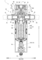
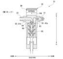
- FIG. 2 is a longitudinal sectional view of the water purifier of the present disclosure.
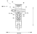
- FIG. FIG. FIG. FIG. FIG. FIG. 2 is a schematic vertical cross-sectional view of the water purifier of the present disclosure in a first mode.
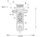
- FIG. 11 is a schematic vertical cross-sectional view of the water purifier of the present disclosure in a second mode.
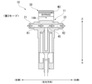
- FIG. 11 is a schematic vertical cross-sectional view of the water purifier of the present disclosure in a third mode.
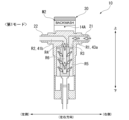
- FIG. 2 is a schematic vertical cross-sectional view of the water purifier of the present disclosure in a first mode.
- FIG. 2 is a schematic vertical cross-sectional view of the water purifier of the present disclosure in a first mode.
- the water purifier 1 includes a water purifier main body 10 and a dial 30.
- the water purifier body 10 is cylindrical and extends vertically around a central axis J.
- the water purifier body 10 includes a valve seat 11, a valve body 12, a filter element 13, a first cover member 14, a second cover member 15, a third cover member 16, a switching member 17, and a drain handle 18.
- the valve seat 11 is formed of a metal material, for example.
- the valve seat 11 has a water inlet 21, a water outlet 22, a water passage R1, a water passage R2, and a fitting hole 23.
- a water supply pipe P1 is connected to the water inlet 21. Water enters the water inlet 21 via the pipe P1. For example, clean water enters the water inlet 21 via the pipe P1.
- a water outlet pipe P2 is connected to the water outlet 22.
- the water outlet 22 allows the water that has passed through the filter element 13, for example, to exit.
- the water passage R1 extends in a radial direction centered on the central axis J.
- the water passage R1 is arranged coaxially with the water inlet section 21. Water entering from the water inlet section 21 is introduced into the water passage R1.
- the water passage R2 extends in a radial direction centered on the central axis J.
- the water passage R2 is arranged coaxially with the water outlet section 22. Water passing through the water passage R2 is introduced into the water outlet section 22 and then flows out of the pipe P2.
- the water inlet section 21 and the water outlet section 22 are arranged circumferentially apart about the central axis J. As an example, the water inlet section 21 and the water outlet section 22 are arranged 180 degrees apart in the circumferential direction. As an example, the water passage R1 and the water passage R2 are arranged 180 degrees apart in the circumferential direction.
- the fitting hole 23 extends in the vertical direction about the central axis J. The radially inner ends of the water passage R1 and the water passage R2 open into the fitting hole 23.
- the water inlet section 21 and the water outlet section 22 are each provided with a direction indicator section 3 that indicates the water flow direction.
- the direction indicator section 3 may be provided on only one of the water inlet section 21 and the water outlet section 22.
- the direction indicator section 3 is provided on the front side and the back side of the water inlet section 21 and the water outlet section 22, respectively.
- the direction in which the water inlet section 21 and the water outlet section 22 are arranged with respect to the central axis J is referred to as the left-right direction
- the side in which the water inlet section 21 is arranged is referred to as the left side
- the side in which the water outlet section 22 is arranged is referred to as the right side.
- the direction perpendicular to the left-right direction and the up-down direction is referred to as the facing direction in which the worker faces.
- the facing direction when the water flow at the installation location is from left to right, the side facing the worker is referred to as the front side, and when the water flow is from right to left, the side facing the worker is referred to as the back side.
- the valve body 12 is formed of a resin material, for example.
- the outer peripheral surface 12a of the valve body 12 is fitted liquid-tightly into the fitting hole 23 in the valve seat 11 so as to be rotatable in the circumferential direction about the central axis J.
- the left-right position of the valve body 12 is the position in the first mode, which will be described later, used when removing solid components in the water that has entered through the water inlet 21.
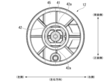
- the valve body 12 has a disk portion 41, a protrusion portion 42, an outer cylinder portion 43, an inner cylinder portion 44, and a through hole 45.
- the disk portion 41 is formed in a disk shape centered on the central axis J. As shown in Figures 4 and 5, the disk portion 41 has a protruding wall 41a that protrudes downward to the right of the central axis J.
- the protrusion 42 is formed in a cylindrical shape extending upward from the disk portion 41. As shown in FIG. 4, the protrusion 42 has flat surfaces 42a formed on both radial sides to prevent rotation. The flat surfaces 42a are parallel to each other.
- the outer tube portion 43 is formed in a cylindrical shape extending downward from the outer edge of the disc portion 41. To the right of the central axis J, the outer tube portion 43 extends downward from the outer edge of the protruding wall 41a.
- the inner tube portion 44 is formed in a cylindrical shape extending downward from the disc portion 41. The inner tube portion 44 is disposed radially inward and spaced apart from the outer tube portion 43. To the right of the central axis J, the inner tube portion 44 extends downward from the inner edge of the protruding wall 41a. Below the disc portion 41, the space between the outer tube portion 43 and the inner tube portion 44 forms a water passage R3. The internal space of the inner tube portion 44 forms a water passage R4 extending in the vertical direction.
- the outer tube portion 43 has a through hole 43a that penetrates in the left-right direction on the left side.
- the radially inner end of the through hole 43a opens into the water passage R3.
- the protruding wall 41a has a through hole 41b that penetrates in the left-right direction.
- the radially inner end of the through hole 41b opens into the water passage R4.
- the through hole 45 penetrates the valve body 12 in the opposing direction.
- the vertical position of the through hole 45 is a position that is included in the vertical range of the through holes 43a and 41b.
- the through hole 45 faces and communicates with the water passage R1 and the water passage R2.
- the switching member 17 is formed of a resin material, for example.
- the switching member 17 is attached to the upper side of the valve body 12.
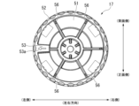
- the switching member 17 has a disk portion 51, a first peripheral wall portion 52, a protrusion portion 53, a cylindrical portion 54, a cylindrical portion 55, and a rib portion 56.
- the disk portion 51 is formed in a disk shape centered on the central axis J.
- the first peripheral wall portion 52 is formed in a cylindrical shape extending upward from the outer edge of the disk portion 51.
- the protrusion 53 protrudes radially inward from the first peripheral wall portion 52 centered on the central axis J.
- the protrusion 53 is formed, for example, at the same height as the first peripheral wall portion 52. As shown in FIG. 6, one protrusion 53 is provided at the left side position.
- a protrusion indicator 53a is formed on the upper surface of the protrusion 53, which indicates that it is a protrusion 53 and the circumferential position where it is attached to the valve body 12. As an example, the protrusion indicator 53a is an arrow pointing radially outward.
- the cylindrical portion 54 extends downward from the disc portion 51 and is formed in a cylindrical shape with a bottom wall 54a at its lower end.
- the cylindrical portion 55 is tubular and extends downward from the bottom wall 54a with the central axis J as its center.
- the protrusion 42 of the valve body 12 fits into the inside of the cylindrical portion 55 from below around the entire circumference. With the protrusion 42 fitting into the inside of the cylindrical portion 55 around the entire circumference, the switching member 17 is fixed in a state where it is prevented from rotating relative to the valve body 12. As the switching member 17 rotates around the central axis J, the valve body 12 rotates in an integrated state.
- the rib portion 56 extends radially inward from the first peripheral wall portion 52.
- the rib portion 56 extends upward from the disk portion 51.
- the upper end of the rib portion 56 is located below the upper end of the first peripheral wall portion 52.
- the rib portion 56 is disposed at a position of 60 degrees and a position of 120 degrees in the counterclockwise direction corresponding to one side in the circumferential direction when viewed from the front.
- Two rib portions 56 are disposed at a pitch of 60 degrees on the front side in the opposing direction.
- the rib portions 56 are respectively arranged at 60 degrees and 120 degrees in the clockwise direction corresponding to the other side in the circumferential direction when viewed from the front. Two rib portions 56 are arranged on the back side in the opposing direction. Two rib portions 56 are arranged at a pitch of 60 degrees on the back side in the opposing direction.
- the filter element 13 is disposed below the valve seat 11 and the valve body 12.
- the filter element 13 has a housing 13A, a filter 13B, and a drainage section 13C.
- the housing 13A is formed, for example, from a resin material.
- the housing 13A is formed in a cylindrical shape extending in the vertical direction.
- the housing 13A is open at the upper end.
- the housing 13A has a male thread at the upper end, and is fixed to the valve seat 11 from below by being screwed into a female thread formed in the valve seat 11.
- the upper end of the housing 13A is formed with a diameter larger than the diameter of the fitting hole 23.
- Filter 13B extends vertically around central axis J. Filter 13B is disposed inside housing 13A and radially spaced from housing 13A. The space between housing 13A and filter 13B forms water passage R5. The internal space of filter 13B forms water passage R6.
- the upper end of filter 13B fits liquid-tight from below into inner tube portion 44 of valve body 12.
- water passage R6 communicates with water passage R4.
- the lower end of filter 13B is connected to the lower end of housing 13A and drainage portion 13C.
- the drainage section 13C is connected to the filter 13B from below.
- the drainage section 13C has a drainage channel 13d that extends vertically around the central axis J.
- the drainage channel 13d is connected to the water passage R5.
- a drainage pipe P3 can be connected to the lower end of the drainage section 13C. Water drained from the drainage channel 13d is discharged via the pipe P3.
- the drain handle 18 is positioned on the side facing the operator when the water flow at the installation location is from left to right.
- the drain handle 18 is positioned radially outward of the drain channel 13d.
- the drain handle 18 has a circular shape when viewed from the front.
- the drain handle 18 is rotatable about an axis that extends in the opposing direction. When rotated, the drain handle 18 can switch between opening and closing the drain channel 13d.
- the first cover member 14 is formed of a resin material, for example.
- the first cover member 14 is formed in a cylindrical shape that covers the upper side of the water purifier main body 10 from the radial outside.
- the first cover member 14 covers the periphery of the valve seat 11 and the valve body 12 from the radial outside while leaving the upper side of the switching member 17 exposed.
- the outer diameter of the first cover member 14 and the outer diameter of the dial 30 are the same.
- the water inlet section 21 and the water outlet section 22 are provided to protrude radially outward from the first cover member 14.
- the first cover member 14 has an indicator portion 14A located near the upper end on the outer circumferential surface. If the center position of the water inlet portion 21 in the circumferential direction is taken as 0 degrees, the indicator portion 14A is located at a position 90 degrees counterclockwise corresponding to one side in the circumferential direction when viewed from the front, and at a position 90 degrees clockwise corresponding to the other side in the circumferential direction. As an example, the indicator portion 14A is formed in a dot shape.
- the second cover member 15 is formed, for example, from a resin material.
- the second cover member 15 is formed in a cylindrical shape that covers the lower side of the first cover member 14 in the water purifier body 10 from the outside in the radial direction.
- the second cover member 15 covers the periphery of the filter element 13 from the outside in the radial direction.
- the outer diameter of the second cover member 15 is the same as the outer diameter of the first cover member 14.
- the third cover member 16 is formed, for example, from a resin material.
- the third cover member 16 is formed in a cylindrical shape that covers the lower side of the second cover member 15 in the water purifier body 10 from the outside in the radial direction.
- the third cover member 16 covers the periphery of the drainage section 13C from the outside in the radial direction.
- the outer diameter of the third cover member 16 and the outer diameter of the second cover member 15 are the same.
- the outer diameter of the dial 30, the outer diameter of the first cover member 14, the outer diameter of the second cover member 15, and the outer diameter of the third cover member 16 are the same.
- the dial 30 is detachably attached to the water purifier body 10.
- the dial 30 is detachably attached to the switching member 17.
- the dial 30 can rotate circumferentially relative to the water purifier body 10.
- the dial 30 can select from a number of modes in which water introduced from the water inlet 21 flows out through different routes depending on the circumferential position relative to the water purifier body 10.
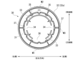
- the dial 30 has a top wall portion 31, a side wall portion 32, a second peripheral wall portion 33, a recess 34, a second recess 35, a third recess 36, and an engagement portion 37.
- the top wall portion 31 is formed in a disk shape located at the top of the dial 30.
- the side wall portion 32 is formed in a cylindrical shape extending downward from the outer edge of the top wall portion 31.
- the side wall portion 32 has a knurled portion 32a on the upper side of the outer circumferential surface.
- the knurled portion 32a is formed around the entire circumference.
- the side wall 32 has markings M1, M2, and M3 below the knurled portion 32a on the outer circumferential surface.
- the markings M1, M2, and M3 indicate information about a number of modes in which water introduced from the water inlet 21 exits through different paths. Details of the markings M1, M2, and M3 will be described later.
- the second peripheral wall portion 33 extends downward from the top wall portion 31 of the dial 30.
- the second peripheral wall portion 33 extends in the circumferential direction centered on the central axis J.
- the radial position of the second peripheral wall portion 33 is a position where it overlaps with the protrusion 53 and the rib portion 56 of the switching member 17 in the direction along the central axis J.
- the position of the lower end of the second peripheral wall portion 33 is a position that is lower than the upper ends of the protrusion 53 and the rib portion 56 when the dial 30 is attached to the switching member 17.
- the position of the lower end of the second peripheral wall portion 33 is a position where it interferes with the protrusion 53 and the rib portion 56 when the dial 30 is attached to the switching member 17 without being aligned in the circumferential direction.
- the recess 34 is formed in the second peripheral wall portion 33.
- the recess 34 has a shape in which the second peripheral wall portion 33 is locally missing.
- the recess 34 is disposed in a radial position where it overlaps with the protrusion 53 in the direction along the central axis J when the dial 30 is attached to the switching member 17.
- the recess 34 is disposed at a position of 0 degrees and a position of 180 degrees.
- the circumferential dimension of the recess 34 is larger than the circumferential dimension of the protrusion 53. The recess 34 can fit into the protrusion 53 when the dial 30 is attached to the switching member 17.
- the dial 30 can be attached to the switching member 17 in a first position where the protrusion 53 fits when the recess 34 is at 0 degrees in the circumferential direction, and in a second position where the protrusion 53 fits when the recess 34 is rotated 180 degrees in the circumferential direction and the recess 34 is at 180 degrees in the circumferential direction.
- the second recess 35 is formed in the second peripheral wall portion 33.
- the second recess 35 has a shape in which the second peripheral wall portion 33 is locally missing. If the center position of the protrusion 53 on the switching member 17 in the circumferential direction is set to 0 degrees, the second recess 35 is disposed at a position of 60 degrees and a position of 120 degrees on the rear side. When the dial 30 is attached to the switching member 17, the second recess 35 is disposed at a radial position where it overlaps with the rib portion 56 in the direction along the central axis J. The circumferential dimension of the second recess 35 is greater than the circumferential dimension of the rib portion 56.
- the dial 30 is shifted circumferentially from the first and second positions where the protrusions 53 fit into the recesses 34 relative to the switching member 17, the second peripheral wall portion 33 and the rib portion 56 interfere with each other in the direction along the central axis J.
- the dial 30 is attached to the switching member 17 in the first and second circumferential positions where the protrusions 53 fit into the recesses 34 relative to the switching member 17, the rib portion 56 can fit into the second recess 35 without interfering with each other in the direction along the central axis J.
- the third recess 36 is formed in the second peripheral wall 33.
- the third recess 36 is formed in a shape in which the second peripheral wall 33 is locally missing.
- the third recess 36 is formed in a range exceeding 60 degrees in the circumferential direction, centered on a position 90 degrees toward the front side, assuming that the center position of the protrusion 53 in the switching member 17 in the circumferential direction is 0 degrees.
- the rib portion 56 can fit into the third recess 36 without interference in the direction along the central axis J when the dial 30 is attached to the switching member 17 at either the first or second circumferential position where the protrusion 53 fits into the recess 34.
- the engaging portion 37 extends downward from the top wall portion 31 at a position radially outward from the first peripheral wall portion 52 of the switching member 17.
- the engaging portion 37 has a claw portion 37a at its lower end that protrudes radially inward.
- the engaging portion 37 is a snap fit.
- the dial 30 is attached to the switching member 17 at either the first or second circumferential position, the claw portion 37a of the engaging portion 37 engages with the lower end of the disc portion 51 of the switching member 17 from below.
- Two engaging portions 37 are arranged facing each other in the radial direction.
- the engaging portions 37 are arranged at 0 degrees and 180 degrees in the circumferential direction, assuming that the center position of the protrusion 53 of the switching member 17 is 0 degrees.
- the two engaging portions 37 engage with the lower end of the disc portion 51 of the switching member 17 from below at the claw portion 37a, so that the dial 30 is held in the switching member 17 in a direction along the central axis J.
- Notation M1 is positioned at 90 degrees counterclockwise in a plan view, corresponding to one side in the circumferential direction, assuming that the left side, which is the center position of the water inlet section 21 in the circumferential direction, is 0 degrees.
- Notation M1 is positioned on the front side of the outer circumferential surface of side wall section 32.
- Notation M1 is positioned on the side where the water flow at the installation location is from left to right when dial 30 is attached to switching member 17 in the first circumferential position.
- the notation of notation M1 corresponds to the first mode in which water introduced from water inlet section 21 is discharged through the first path, as shown in Figure 8.
- the first mode is set when the dial 30 and the switching member 17 are rotated and the notation M1 is aligned using the indicator portion 14A as an indicator.
- the first mode is the mode when the valve body 12 is rotated to a position where the through hole 43a in the valve body 12 faces and communicates with the water passage R1, and the through hole 41b faces and communicates with the water passage R2.
- the first path in the first mode is a path along which water introduced from the water inlet 21 passes through water passage R1, through hole 43a, water passage R3, water passage R5, water passage R6, water passage R4, through hole 41b, water passage R2, and the water outlet 22 before being discharged from the pipe P2.
- the first mode is a normal mode in which solid components in the water introduced from the water inlet 21 are removed by the filter 13B and then purified water is discharged, and is shown as "NORMAL" in the notation M1 as an example.
- the notation M2 is positioned at a position 90 degrees clockwise, which corresponds to the other side in the circumferential direction in a plan view.
- Notation M2 is positioned on the rear side of the outer circumferential surface of side wall section 32.
- Notation M2 is positioned on the rear side when dial 30 is attached to switching member 17 in the first circumferential position.
- the notation of notation M2 corresponds to the second mode in which water introduced from the water inlet section 21 is drained through the second path, as shown in Figure 9.
- the second mode is set when the dial 30 and the switching member 17 are rotated and the notation M2 is aligned with the index portion 14A as an index.
- the second mode is the mode when the valve body 12 is rotated to a position where the through hole 43a in the valve body 12 faces and communicates with the water passage R2, and the through hole 41b faces and communicates with the water passage R1.
- the second path in the second mode is a path in which water introduced from the water inlet 21 travels through water passage R2, through hole 41b, water passage R4, water passage R6, water passage R5, and drainage passage 13d before being drained from pipe P3.
- drainage handle 18 is rotated to open drainage passage 13d.
- the second mode is a backwash mode in which the introduced water is caused to flow from the inside to the outside of filter 13B, thereby discharging solid components that have been removed from the water in filter element 13 and remain, and is shown as "BACKWASH" in notation M2 as an example.
- Notation M3 is positioned at 0 degrees in a plan view, with the left side being the center position of the water inlet section 21 in the circumferential direction, being 0 degrees. Notation M3 is positioned on the left side of the outer peripheral surface of side wall section 32. Notation M3 is positioned on the left side when dial 30 is attached to switching member 17 in the first circumferential position. The notation of notation M3 corresponds to the third mode in which water introduced from water inlet section 21 is discharged through a third route, as shown in FIG. 10.
- the third mode is set when the dial 30 and the switching member 17 are rotated and the notation M3 is aligned with the index portion 14A as an index.
- the third mode is set when the valve body 12 is rotated to a position where the through hole 45 in the valve body 12 faces and communicates with the water passages R1 and R2.
- the third path in the third mode is a path through which water introduced from the water inlet 21 flows through the water passage R1, the through hole 45, the water passage R2, and the water outlet 22 before flowing out from the pipe P2.
- the third path is a path through which water introduced from the water inlet 21 does not pass through the filter element 13.
- water can flow out from the pipe P2 when the filter element 13 is removed from the water purifier body 10 for cleaning.
- the third mode is a bypass mode that allows water introduced from the water inlet 21 to flow through the water outlet 22.
- the third mode is indicated in the notation M3 as "BYPASS.”
- the "NORMAL" marking M1 is located on the front side. The operator can easily see that the water purifier 1 is in normal mode.
- the water purifier 1 may have the water supply pipe P1 connected to the water inlet 21 on the right side.
- the water purifier 1 is set to normal mode, but the indicator 14A and the "BACKWASH" marking M2 indicating the second mode are located on the front side.
- the operator moves the claws 37a radially outward by pulling the dial 30 upward, releasing the dial 30 from the switching member 17.
- the operator removes the dial 30 from the switching member 17 and then rotates it 180 degrees.
- the operator attaches the dial 30 to the switching member 17 at a circumferential position where the recess 34 fits into the protrusion 53 in the second position.
- the "NORMAL" marking M1 which corresponds to the actual mode of the water purifier 1, is located on the front side.
- the notation part M1 can be attached to the water purifier body 10 at a first position away from the water inlet part 21 on one side in the circumferential direction, and at a second position away from the water inlet part 21 on the other side in the circumferential direction, so that the mode can be easily switched regardless of the positions of the pipes P1 and P2 connected to the water inlet part 21 and the water outlet part 22.
- the outer diameter of the water purifier body 10 and the outer diameter of the dial 30 are the same, which improves the aesthetic appearance.
- the dial 30 is attached to the upper side of the water purifier body 10, making it easier to grip when switching modes and improving operability.
- the water purifier body 10 is a prefilter having a filter 13B that removes solid components from the water, but the configuration is not limited to this.
- the water purifier may also have a water purification filter that is disposed downstream of the prefilter and removes dissolved components from the water.
- the present disclosure includes the following aspects:
- a water purifier comprising: a water purifier body having a water inlet and a water outlet arranged at a distance from each other in the circumferential direction around a central axis; and a dial that is detachably attached to the water purifier body and can rotate in the circumferential direction relative to the water purifier body when attached to the water purifier body, and that can select from a plurality of modes in which water introduced from the water inlet is discharged through different paths depending on the circumferential position relative to the water purifier body, the dial having a plurality of markings on its outer circumferential surface that indicate information relating to the plurality of modes, one of the markings being attachable to the water purifier body at a first position that is away from the water inlet on one side in the circumferential direction and a second position that is away from the water inlet on the other side in the circumferential direction.
Landscapes
- Life Sciences & Earth Sciences (AREA)
- Hydrology & Water Resources (AREA)
- Engineering & Computer Science (AREA)
- Environmental & Geological Engineering (AREA)
- Water Supply & Treatment (AREA)
- Chemical & Material Sciences (AREA)
- Organic Chemistry (AREA)
- Water Treatment By Sorption (AREA)
Abstract
La présente divulgation concerne un épurateur d'eau pouvant facilement changer de mode, indépendamment de la position des tuyaux raccordés à une entrée d'eau et à une sortie d'eau. L'épurateur d'eau comprend : un corps d'épurateur d'eau avec une entrée d'eau et une sortie d'eau disposées à distance l'une de l'autre dans une direction circonférentielle centrée sur l'axe central ; et un cadran amovible disposé sur le corps d'épurateur d'eau et pouvant tourner dans la direction circonférentielle par rapport au corps d'épurateur d'eau lorsqu'il est monté sur celui-ci, le cadran permettant de sélectionner parmi une pluralité de modes dans lesquels de l'eau introduite à partir de l'entrée d'eau est évacuée par différentes voies en fonction de la position par rapport au corps d'épurateur d'eau dans la direction circonférentielle. Le cadran comporte plusieurs parties de repérage indiquant des informations relatives à la pluralité de modes sur sa surface circonférentielle. L'une des parties de repérage peut être montée sur le corps d'épurateur d'eau à une première position séparée de l'entrée d'eau dans une direction de la direction circonférentielle, et à une seconde position séparée de l'entrée d'eau dans l'autre direction de la direction circonférentielle.
Priority Applications (1)
| Application Number | Priority Date | Filing Date | Title |
|---|---|---|---|
| PCT/JP2023/020971 WO2024252514A1 (fr) | 2023-06-06 | 2023-06-06 | Épurateur d'eau |
Applications Claiming Priority (1)
| Application Number | Priority Date | Filing Date | Title |
|---|---|---|---|
| PCT/JP2023/020971 WO2024252514A1 (fr) | 2023-06-06 | 2023-06-06 | Épurateur d'eau |
Publications (1)
| Publication Number | Publication Date |
|---|---|
| WO2024252514A1 true WO2024252514A1 (fr) | 2024-12-12 |
Family
ID=93795458
Family Applications (1)
| Application Number | Title | Priority Date | Filing Date |
|---|---|---|---|
| PCT/JP2023/020971 Ceased WO2024252514A1 (fr) | 2023-06-06 | 2023-06-06 | Épurateur d'eau |
Country Status (1)
| Country | Link |
|---|---|
| WO (1) | WO2024252514A1 (fr) |
Citations (4)
| Publication number | Priority date | Publication date | Assignee | Title |
|---|---|---|---|---|
| JPS5610306A (en) * | 1979-07-05 | 1981-02-02 | Mitsubishi Heavy Ind Ltd | Filter |
| WO2007126047A1 (fr) * | 2006-04-27 | 2007-11-08 | Mrc Home Products Co., Ltd. | Epurateur d'eau et vanne d'inversion |
| CN105688477A (zh) * | 2016-03-18 | 2016-06-22 | 厦门建霖工业有限公司 | 一种拆芯可持续供水的预过滤器 |
| JP2017170433A (ja) * | 2016-03-22 | 2017-09-28 | エルジー エレクトロニクス インコーポレイティド | 浄水装置 |
-
2023
- 2023-06-06 WO PCT/JP2023/020971 patent/WO2024252514A1/fr not_active Ceased
Patent Citations (4)
| Publication number | Priority date | Publication date | Assignee | Title |
|---|---|---|---|---|
| JPS5610306A (en) * | 1979-07-05 | 1981-02-02 | Mitsubishi Heavy Ind Ltd | Filter |
| WO2007126047A1 (fr) * | 2006-04-27 | 2007-11-08 | Mrc Home Products Co., Ltd. | Epurateur d'eau et vanne d'inversion |
| CN105688477A (zh) * | 2016-03-18 | 2016-06-22 | 厦门建霖工业有限公司 | 一种拆芯可持续供水的预过滤器 |
| JP2017170433A (ja) * | 2016-03-22 | 2017-09-28 | エルジー エレクトロニクス インコーポレイティド | 浄水装置 |
Similar Documents
| Publication | Publication Date | Title |
|---|---|---|
| CN101426733B (zh) | 净水器和切换阀 | |
| JP4903169B2 (ja) | 浄水器 | |
| WO2024252514A1 (fr) | Épurateur d'eau | |
| TWI604877B (zh) | 淨水器 | |
| JP5872210B2 (ja) | 浄水機能付き水栓 | |
| JP3569821B2 (ja) | 浄水器を有した水栓 | |
| WO2009025413A1 (fr) | Filtre purificateur d'eau ayant une fonction de lavage de filtre | |
| JP4825939B2 (ja) | 浄水機能付き吐水ヘッド | |
| JP5872498B2 (ja) | シャワー装置 | |
| JP3779566B2 (ja) | 浄水装置及びその設置施工方法 | |
| WO2024252516A1 (fr) | Gabarit de purificateur d'eau | |
| KR20230146807A (ko) | 수전장치 | |
| JP3779560B2 (ja) | 浄水装置 | |
| JP2024026943A (ja) | 浄水器 | |
| JP4575556B2 (ja) | 浄水機能付きシャワーヘッド | |
| JPH0712671U (ja) | 湯水混合栓 | |
| CN216778160U (zh) | 一种前置过滤器 | |
| JP2002356891A (ja) | 緊急遮断弁付きの水栓及び水栓用のカートリッジ | |
| JP4801207B2 (ja) | 浄水機能付きシャワーヘッド | |
| KR102818629B1 (ko) | 디지털 정수기 | |
| JP5345560B2 (ja) | 浄水器 | |
| JP2600199Y2 (ja) | 浄水器 | |
| JP2006275248A (ja) | 給水栓の弁装置 | |
| JP4473423B2 (ja) | 浄水器の流路切り替え装置 | |
| JPH04102694U (ja) | 浄水器 |
Legal Events
| Date | Code | Title | Description |
|---|---|---|---|
| 121 | Ep: the epo has been informed by wipo that ep was designated in this application |
Ref document number: 23940620 Country of ref document: EP Kind code of ref document: A1 |
|
| NENP | Non-entry into the national phase |
Ref country code: DE |