EP3219594B1 - Structure de retenue de couvercle - Google Patents
Structure de retenue de couvercle Download PDFInfo
- Publication number
- EP3219594B1 EP3219594B1 EP17160576.9A EP17160576A EP3219594B1 EP 3219594 B1 EP3219594 B1 EP 3219594B1 EP 17160576 A EP17160576 A EP 17160576A EP 3219594 B1 EP3219594 B1 EP 3219594B1
- Authority
- EP
- European Patent Office
- Prior art keywords
- lid
- handle
- pipe handle
- power supply
- supported
- Prior art date
- Legal status (The legal status is an assumption and is not a legal conclusion. Google has not performed a legal analysis and makes no representation as to the accuracy of the status listed.)
- Active
Links
Images


Classifications
-
- B—PERFORMING OPERATIONS; TRANSPORTING
- B62—LAND VEHICLES FOR TRAVELLING OTHERWISE THAN ON RAILS
- B62J—CYCLE SADDLES OR SEATS; AUXILIARY DEVICES OR ACCESSORIES SPECIALLY ADAPTED TO CYCLES AND NOT OTHERWISE PROVIDED FOR, e.g. ARTICLE CARRIERS OR CYCLE PROTECTORS
- B62J11/00—Supporting arrangements specially adapted for fastening specific devices to cycles, e.g. supports for attaching maps
-
- B—PERFORMING OPERATIONS; TRANSPORTING
- B62—LAND VEHICLES FOR TRAVELLING OTHERWISE THAN ON RAILS
- B62J—CYCLE SADDLES OR SEATS; AUXILIARY DEVICES OR ACCESSORIES SPECIALLY ADAPTED TO CYCLES AND NOT OTHERWISE PROVIDED FOR, e.g. ARTICLE CARRIERS OR CYCLE PROTECTORS
- B62J45/00—Electrical equipment arrangements specially adapted for use as accessories on cycles, not otherwise provided for
-
- B—PERFORMING OPERATIONS; TRANSPORTING
- B62—LAND VEHICLES FOR TRAVELLING OTHERWISE THAN ON RAILS
- B62K—CYCLES; CYCLE FRAMES; CYCLE STEERING DEVICES; RIDER-OPERATED TERMINAL CONTROLS SPECIALLY ADAPTED FOR CYCLES; CYCLE AXLE SUSPENSIONS; CYCLE SIDE-CARS, FORECARS, OR THE LIKE
- B62K11/00—Motorcycles, engine-assisted cycles or motor scooters with one or two wheels
- B62K11/14—Handlebar constructions, or arrangements of controls thereon, specially adapted thereto
-
- H—ELECTRICITY
- H01—ELECTRIC ELEMENTS
- H01R—ELECTRICALLY-CONDUCTIVE CONNECTIONS; STRUCTURAL ASSOCIATIONS OF A PLURALITY OF MUTUALLY-INSULATED ELECTRICAL CONNECTING ELEMENTS; COUPLING DEVICES; CURRENT COLLECTORS
- H01R13/00—Details of coupling devices of the kinds covered by groups H01R12/70 or H01R24/00 - H01R33/00
- H01R13/44—Means for preventing access to live contacts
- H01R13/447—Shutter or cover plate
-
- H—ELECTRICITY
- H01—ELECTRIC ELEMENTS
- H01R—ELECTRICALLY-CONDUCTIVE CONNECTIONS; STRUCTURAL ASSOCIATIONS OF A PLURALITY OF MUTUALLY-INSULATED ELECTRICAL CONNECTING ELEMENTS; COUPLING DEVICES; CURRENT COLLECTORS
- H01R13/00—Details of coupling devices of the kinds covered by groups H01R12/70 or H01R24/00 - H01R33/00
- H01R13/73—Means for mounting coupling parts to apparatus or structures, e.g. to a wall
-
- B—PERFORMING OPERATIONS; TRANSPORTING
- B62—LAND VEHICLES FOR TRAVELLING OTHERWISE THAN ON RAILS
- B62J—CYCLE SADDLES OR SEATS; AUXILIARY DEVICES OR ACCESSORIES SPECIALLY ADAPTED TO CYCLES AND NOT OTHERWISE PROVIDED FOR, e.g. ARTICLE CARRIERS OR CYCLE PROTECTORS
- B62J43/00—Arrangements of batteries
- B62J43/30—Arrangements of batteries for providing power to equipment other than for propulsion
-
- H—ELECTRICITY
- H01—ELECTRIC ELEMENTS
- H01R—ELECTRICALLY-CONDUCTIVE CONNECTIONS; STRUCTURAL ASSOCIATIONS OF A PLURALITY OF MUTUALLY-INSULATED ELECTRICAL CONNECTING ELEMENTS; COUPLING DEVICES; CURRENT COLLECTORS
- H01R13/00—Details of coupling devices of the kinds covered by groups H01R12/70 or H01R24/00 - H01R33/00
- H01R13/46—Bases; Cases
- H01R13/52—Dustproof, splashproof, drip-proof, waterproof, or flameproof cases
- H01R13/5213—Covers
-
- H—ELECTRICITY
- H01—ELECTRIC ELEMENTS
- H01R—ELECTRICALLY-CONDUCTIVE CONNECTIONS; STRUCTURAL ASSOCIATIONS OF A PLURALITY OF MUTUALLY-INSULATED ELECTRICAL CONNECTING ELEMENTS; COUPLING DEVICES; CURRENT COLLECTORS
- H01R2201/00—Connectors or connections adapted for particular applications
- H01R2201/26—Connectors or connections adapted for particular applications for vehicles
Definitions
- the present invention relates to a lid retaining structure for a power supply socket through which supply of electrical power is carried out from a vehicle battery to an external device through a power supply terminal and an external terminal, by inserting the external terminal into an entrance of the main body portion, and connecting the external terminal to the power supply terminal of the main body portion, in a state in which a lid is removed from the main body portion.
- US 6 104 099 A discloses a four-wheeled all-terrain vehicle, wherein a handlebar bracket is attached to the upper end of a steering shaft, a handlebar has a central part fastened to the handlebar bracket with clamping members, a bracket is attached to the clamping member, and a handlebar cover is fixedly attached to the bracket so as to cover the central part of the handlebar from above.
- An accessory socket is disposed inside the handlebar cover and is held on the bracket.
- An accessory plug electrically connected to an external electric apparatus can be inserted inside the handlebar cover through a recess formed in a side wall of the handlebar cover and can be connected to the accessory socket.
- DE 20 2012 003 103 U1 which shows all the features of the preamble of independent claim 1, discloses an electrical socket for a vehicle that comprises an insulated housing with a front opening and further comprises a USB socket, which is inserted through the opening into the housing.
- a lid is connected to the electrical socket via a band to protect the electrical socket from water and rain.
- the lid further comprises an element for removing the lid from the electrical socket.
- accessories such as a navigation device, a smart phone, etc. are arranged in the vicinity of a steering handle of a vehicle such as a motorcycle or the like in order to improve visibility of a vehicle occupant with respect to such accessories.
- a power supply socket in the vicinity of the handle in order to supply electrical power to such accessories from the vehicle battery.
- the present invention has been devised taking into consideration the aforementioned problem, and has the object of providing a lid retaining structure in which, by suitably arranging the power supply socket in the vicinity of a handle of a vehicle, it is possible for electrical power to be supplied to an accessory arranged in the vicinity of the handle.
- the present invention relates to a combination of a lid retaining structure and a power supply socket, wherein the power supply socket is equipped with a main body portion including a power supply terminal configured to supply electrical power from a battery of a vehicle by insertion of an external terminal through an entrance, and a lid configured to cover the entrance.
- the lid retaining structure includes a handle of the vehicle, a component supporting section configured to support a component of the vehicle on the handle, and a stay configured to support the power supply socket on the handle.
- the handle includes a pipe handle supported steerably on a front portion of the vehicle, and a grip disposed on an end of the pipe handle and which is gripped by an occupant of the vehicle.
- the component supporting section supports the component on the pipe handle at a location closer to a vehicle body center than the grip.
- the stay is equipped with at least one supported section supported on the pipe handle, a flat section jointly forming a gap between the pipe handle and the flat section and which extends upwardly from the at least one supported section, and a main body supporting section, which is bent from the flat section so as to separate away from the handle, and configured to support the main body portion.
- the main body portion is supported on the main body supporting section so that the entrance is located above the main body supporting section.
- the lid is connected to the main body portion via a connecting part at a location above the main body supporting section. The lid, which is detached from the entrance, is retained in a space surrounded by the flat section, the pipe handle, and the component supporting section.
- the lid which is detached from the entrance, is retained in the space, whereby movement of the lid in an axial direction of the pipe handle (in the left and right direction of the vehicle) is restricted by the component supporting section, together with movement of the lid in the front and rear direction of the vehicle being restricted by the pipe handle and the flat section.
- the pipe handle has an annular shape when viewed in cross section
- the gap is substantially in the form of a V-shape, which is wider at the entrance and narrows in the downward direction.
- the power supply socket can be arranged in the vicinity of the handle, and the lid can suitably be retained after removal thereof from the entrance.
- the lid and the connecting part preferably are made from elastic members.
- the lid and the connecting part are made to be elastically deformed, the lid can easily be arranged in the space surrounded by the flat section, the pipe handle, and the component supporting section. Further, due to surface contact between the lid, which is an elastic member, and the flat section, since the frictional force between the lid and the flat section is increased, the retained state of the lid can favorably be maintained.
- the connecting part connects the main body portion and the lid on a side of the handle, and when the vehicle is viewed from the side, the lid, which is detached from the entrance, is rotated about the connecting part by approximately 270 degrees from the entrance toward the handle, and is held in the space such that the connecting part is positioned above the lid. Consequently, when the lid is held in the gap between the pipe handle and the flat section, the connecting part, which is an elastic member, presses on the lid from above. As a result, it is possible to restrict the position of the lid from any direction, i.e., the front and rear direction, the left and right direction, and the up and down direction.
- the component supporting section includes a front support portion arranged in front of the pipe handle and configured to support the component, and a rear support portion disposed behind the pipe handle.
- the front support portion, the rear support portion, and the at least one supported section are supported on the pipe handle as a result of being fastened together in a front and rear direction of the vehicle by at least one fastening member.
- the fastening members are members for fixing to the pipe handle the component supporting section that supports the component.
- the front support portion, the rear support portion, and the supported sections are fastened together in the front and rear direction of the vehicle, whereby the stay can be fixed to the pipe handle while suppressing an increase in the weight of the handle.
- the gap is easily formed between the flat section and the pipe handle.
- the at least one fastening member is provided as a pair of fastening members
- the at least one supported section is provided as a pair of supported sections
- the front support portion, the rear support portion, and the supported sections are supported on the pipe handle as a result of being fastened together in the front and rear direction of the vehicle at locations above and below the pipe handle by using the pair of fastening members.
- the lid includes a lid portion configured to cover the entrance, and a knob portion which protrudes from a side of the lid portion and is thinner than the lid portion.
- the lid which is detached from the entrance, is gripped in the space as a result of the knob portion being arranged in the gap between the pipe handle and the flat section. Consequently, the gap between the pipe handle and the flat section can be made narrower. As a result, it is possible to prevent the power supply socket from protruding in a rearward direction from the pipe handle.
- a lid retaining structure 10 As shown in FIGS. 1 through 3 , a lid retaining structure 10 according to the present embodiment is applied to a motorcycle 12 which serves as a vehicle.
- a handle 14 is provided on a front of the motorcycle 12.
- the handle 14 is equipped with a steerably supported pipe handle 16, which extends in left and right directions from a vehicle body center at the front of the motorcycle 12, and grips 18L, 18R that are gripped by a rider or a vehicle occupant on both ends of the pipe handle 16.
- a component supporting section 20 is fixedly supported at a position closer to the vehicle body center than the right side grip 18R.
- the component supporting section 20 supports a master cylinder 22, which is a component of the motorcycle 12, in front of the pipe handle 16, and also supports a power supply socket 24, which is an accessory socket, behind the pipe handle 16.
- the master cylinder 22 is accommodated in a resin case 26.
- a brake lever 28 is supported on the pipe handle 16 in front of the grip 18R, so as to enable connection thereof to the master cylinder 22.
- a brake fluid pressure is applied from the master cylinder 22 to a braking device provided on a non-illustrated front wheel, and a braking force is applied to the front wheel.
- a vehicle-mounted device 30 (external device), which is used in association with an ETC (Electronic Toll Collection) system, is arranged closer to the vehicle body center than the component supporting section 20, the master cylinder 22, and the power supply socket 24.
- a navigation device 32 (external device) is disposed in front of the pipe handle 16. In this case, a screen 34 of the navigation device 32 is arranged at a central position of the vehicle body in front of the pipe handle 16.
- constituent elements of the motorcycle 12 for example, a rearview mirror, a blinker, a front fender, a fuel tank
- constituent elements of the motorcycle 12 for example, a rearview mirror, a blinker, a front fender, a fuel tank
- the lid retaining structure 10 is a mechanism for retaining a lid 36 of the power supply socket 24 in the vicinity of the pipe handle 16 of the motorcycle 12, and is constituted by the pipe handle 16, the component supporting section 20, and a stay 38, which is supported on the component supporting section 20 while also supporting the power supply socket 24.
- the component supporting section 20 is a metal annular member attached to the pipe handle 16 in surrounding relation to the outer periphery of the pipe handle 16, which also is annular shaped in cross section, and comprises a front support portion 20f disposed in front of the pipe handle 16, and a rear support portion 20r disposed rearwardly of the pipe handle 16. More specifically, when the annular shaped component supporting section 20 is divided in half, the front portion thereof serves as the front support portion 20f, whereas the rearward portion thereof serves as the rear support portion 20r.
- the front support portion 20f supports the master cylinder 22 by being formed integrally with the case 26 in which the master cylinder 22 is accommodated.
- An upper part and a lower part of each of the front support portion 20f and the rear support portion 20r bulge respectively in upward and downward directions, and in such bulging portions, screw holes that extend in front and rear directions are formed, respectively.
- the stay 38 is a plate-shaped member made of metal.
- the stay 38 is equipped with supported sections 38a, 38b, which are capable of being placed in surface contact, respectively, with the rear side of the upper part and the lower part of the rear support portion 20r, a flat section 38c, which is connected to and extends upwardly from the supported sections 38a, 38b, and a main body supporting section 38d, which is bent rearwardly from an upper end of the flat section 38c. Holes of substantially the same diameter as respective screw holes formed in the front support portion 20f and the rear support portion 20r are formed respectively in the supported sections 38a, 38b. Further, a large diameter hole 38e is formed in the main body supporting section 38d.
- the power supply socket 24 includes a bottomed cylindrical main body portion 40 and the lid 36.
- the main body portion 40 includes a power supply opening 42, and a power supply contact 44 (power supply terminal) is provided in an inner part of the power supply opening 42. Further, a ground terminal 46 (power supply terminal) is provided on an inner wall of the power supply opening 42.
- a concave/convex stepped portion 48 is formed on the outer periphery of the main body portion 40.
- a recessed portion of the stepped portion 48 is fitted into the hole 38e of the main body supporting section 38d, whereby the power supply socket 24 is supported on the main body supporting section 38d.
- an entrance 50 of the power supply opening 42 is positioned above the main body supporting section 38d.
- the lid 36 is a waterproof cover for the power supply socket 24, and includes a lid portion 52 having a flat top surface that closes the power supply opening 42. A location above the power supply opening 42 of the main body portion 40 is covered by an opening side seal member 53 which is formed integrally with the lid 36. The opening side seal member 53 and the lid 36 are connected together through a connecting part 54. Consequently, the front side of the lid portion 52 is supported on the main body portion 40 via the connecting part 54 and the opening side seal member 53. Further, a knob portion 56, the thickness of which is thinner than that of the lid portion 52, is provided on a side portion (distal end) of the lid portion 52 that is located on the rearward side. The lid portion 52, the opening side seal member 53, the connecting part 54, and the knob portion 56 are made up from elastic members such as rubber or the like.
- the lid retaining structure 10 in a state in which the pipe handle 16 is sandwiched from front and rear directions between the front support portion 20f and the rear support portion 20r, and the main body supporting section 38d supports the main body portion 40, the pairs of screw holes of the front support portion 20f and the rear support portion 20r are aligned respectively with the pair of holes that are formed in the supported sections 38a, 38b, and thereafter screw members 58a, 58b, which serve as a pair of fastening members, are screwed into the respective screw holes through the respective holes, thereby fastening together the front support portion 20f, the rear support portion 20r, and the supported sections 38a, 38b.
- the upper screw member 58a penetrates through the hole of the upper supported section 38a and is screw-engaged with the screw holes on the upper side of the front support portion 20f and the rear support portion 20r.
- the lower screw member 58b penetrates through the hole of the lower supported section 38b and is screw-engaged with the screw holes on the lower side of the front support portion 20f and the rear support portion 20r.
- the front support portion 20f, the rear support portion 20r, and the stay 38 are fastened together in the front and rear direction at positions above and below the pipe handle 16, and are supported on the pipe handle 16.
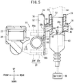
- a gap 60 is formed between the pipe handle 16 and the flat section 38c. That is, a space 62 including the downwardly narrowing substantially V-shaped gap 60 is formed by the pipe handle 16, the component supporting section 20, and the flat section 38c of the stay 38.
- the rider grasps the knob portion 56 of the lid 36, and by rotating the lid portion 52 about the connecting part 54, the entrance 50 of the power supply opening 42 is exposed to the exterior, as shown in FIG. 4 .
- the knob portion 56 is directed downward, and the knob portion 56 is inserted into the gap 60 of the space 62.
- the lid portion 52 of the lid 36 abuts against the flat section 38c, and by surface contact therebetween, positional shifting is prevented as a result of friction between the lid portion 52 and the flat section 38c.
- the lid 36 is more reliably retained in the space 62.
- the pipe handle 16 is annularly shaped in cross section, a possibility exists that the component supporting section 20 may rotate, resulting in positional deviation thereof in the circumferential direction of the pipe handle 16. Even in this case, since the gap 60 remains constant between the pipe handle 16 and the stay 38, positional accuracy of the stay 38 with respect to the circumferential direction can be ignored.
- the location where the lid portion 52 and the connecting part 54 are connected is positioned above the lid 36. Since the lid 36 and the connecting part 54 are elastic members, the lid 36 is pressed from above by the connecting part 54. As a result, the lid 36 can be retained in the space 62.
- a power source terminal 64 of the vehicle-mounted device 30 or the navigation device 32 can be inserted into the power supply opening 42.
- the power supply contact 44 is connected to the positive electrode of a battery 66 of the motorcycle 12, and the ground terminal 46 is connected to the negative electrode of the battery 66 thereof. Therefore, when the positive electrode terminal of the power source terminal 64 and the power supply contact 44 are connected, and the negative electrode terminal and the ground terminal 46 are connected, electrical power from the battery 66 can be supplied to the vehicle-mounted device 30 or the navigation device 32 through the power supply contact 44 and the power source terminal 64.
- the lid retaining structure 10 includes the pipe handle 16, the component supporting section 20, and the stay 38.
- the component supporting section 20 supports the master cylinder 22 on the pipe handle 16 at a location closer to the vehicle body center than the right side grip 18R.
- the stay 38 is equipped with the supported sections 38a, 38b supported on the pipe handle 16 through the component supporting section 20, the flat section 38c, which jointly forms the gap 60 between the pipe handle 16 and the flat section 38c and which extends upwardly from the supported sections 38a, 38b, and a main body supporting section 38d, which is bent from the flat section 38c so as to separate away from the pipe handle 16, and supports the main body portion 40 of the power supply socket 24.
- the main body portion 40 is supported on the main body supporting section 38d such that the entrance 50 is positioned above the main body supporting section 38d.
- the lid 36 is connected to the main body portion 40 via the connecting part 54 at a location above the main body supporting section 38d. In this case, the lid 36, which is detached from the entrance 50, is retained in the space 62 surrounded by the pipe handle 16, the component supporting section 20, and the flat section 38c.
- the lid 36 which is detached from the entrance 50, is retained in the space 62, whereby movement of the lid 36 in an axial direction of the pipe handle 16 (in the left and right direction of the motorcycle 12) is restricted by the component supporting section 20, together with movement of the lid 36 in the front and rear direction being restricted by the pipe handle 16 and the flat section 38c.
- the pipe handle 16 has an annular shape when viewed in cross section as shown in FIGS. 3 through 5 , in the case that the lid 36 is inserted from above into the gap 60 between the pipe handle 16 and the flat section 38c, the gap 60 is substantially in the form of a V-shape, which is wider at the entrance and narrows in a downward direction.
- the knob portion 56 which is most susceptible to swaying, on a distal end (lower end) of the lid 36 with the pipe handle 16 and the flat section 38c, it is possible to maintain the retained state of the lid 36 favorably while suppressing vibrations of the lid 36.
- the power supply socket 24 can be arranged in the vicinity of the pipe handle 16, and the lid 36 can suitably be retained after removal thereof from the entrance 50.
- the power source terminal 64 which is an external terminal
- the power source terminal 64 it is possible to supply electrical power from the battery 66 to the vehicle-mounted device 30 and the navigation device 32, which are accessories arranged in the vicinity of the handle 14.
- an external device such as the navigation device 32 or the like is disposed in the vicinity of the pipe handle 16.
- the power supply socket 24 is supported on the pipe handle 16, whereby supply of electrical power to the external device from the battery 66 can easily be performed through the power supply socket 24.
- the lid 36 and the connecting part 54 are elastic members, the lid 36 and the connecting part 54 are capable of being elastically deformed, and thus it becomes easy for the lid 36 to be arranged in the space 62 surrounded by the pipe handle 16, the component supporting section 20, and the flat section 38c. Further, due to surface contact between the lid 36, which is an elastic member, and the flat section 38c, since the frictional force between the lid 36 and the flat section 38c is increased, the retained state of the lid 36 can favorably be maintained.
- the connecting part 54 connects the main body portion 40 and a front side of the lid 36.
- the lid 36 which is detached from the entrance 50, is rotated about the connecting part 54 by approximately 270 degrees from the entrance 50 toward the pipe handle 16, and is held in the space 62 such that the connecting part 54 is positioned above the lid 36. Consequently, when the lid 36 is held in the gap 60 between the pipe handle 16 and the flat section 38c, the connecting part 54, which is an elastic member, presses on the lid 36 from above. As a result, it is possible to restrict the position of the lid 36 from any direction, i.e., the front and rear direction, the left and right direction, or the up and down direction.
- the component supporting section 20 includes the front support portion 20f arranged in front of the pipe handle 16 and which supports the master cylinder 22, and the rear support portion 20r disposed behind the pipe handle 16.
- the front support portion 20f, the rear support portion 20r, and the supported sections 38a, 38b are supported on the pipe handle 16 as a result of being fastened together by the screw members 58a, 58b in the front and rear direction.
- the screw members 58a, 58b are fastening members for fixing the component supporting section 20 to the pipe handle 16.
- the front support portion 20f, the rear support portion 20r, and the supported sections 38a, 38b are fastened together in the front and rear direction, whereby the stay 38 can be fixed to the pipe handle 16 while suppressing an increase in the weight of the handle 14.
- the gap 60 is easily formed between the flat section 38c and the pipe handle 16.
- the front support portion 20f, the rear support portion 20r, and the supported sections 38a, 38b are fastened together in the front and rear direction at positions above and below the pipe handle 16, and are supported on the pipe handle 16 using the pair of upper and lower screw members 58a, 58b.
- the power supply socket 24 can be fixedly supported more firmly on the pipe handle 16 through the stay 38, it is possible to prevent positional shifting of the power supply socket 24 (and falling off of the power supply socket 24 due to the force of inserting the power source terminal 64), which occurs when the power source terminal 64 is inserted into the entrance 50 that is arranged above the pipe handle 16.
- the lid 36 includes the lid portion 52 that covers the entrance 50, and the knob portion 56 that protrudes from a rear portion of a side of the lid portion 52 and is thinner than the lid portion 52.
- the lid 36 which is detached from the entrance 50, is gripped in the space 62 as a result of the knob portion 56 being arranged in the gap 60 between the pipe handle 16 and the flat section 38c. Consequently, the gap 60 can be made narrower. As a result, it is possible to prevent the power supply socket 24 from protruding in a rearward direction from the pipe handle 16.
Landscapes
- Engineering & Computer Science (AREA)
- Mechanical Engineering (AREA)
- Steering Devices For Bicycles And Motorcycles (AREA)
- Battery Mounting, Suspending (AREA)
Claims (6)
- Combinaison composée d'une structure de retenue de couvercle (10) et d'une prise d'alimentation électrique (24),
dans laquelle la prise d'alimentation électrique (24) est équipée d'une partie de corps principal (40) comprenant une borne d'alimentation électrique (44, 46) configurée pour fournir l'alimentation électrique depuis une batterie (66) d'un véhicule (12) par l'insertion d'une borne externe (64) par une entrée (50), et un couvercle (36) configuré pour recouvrir l'entrée (50),
dans laquelle la structure de retenue de couvercle (10) comprend :une poignée (14) du véhicule (12) ;une section de support de composant (20) configurée pour supporter un composant (22) du véhicule (12) sur la poignée (14) ; etun étai (38) configuré pour supporter la prise d'alimentation électrique (24) sur la poignée (14) ;dans laquelle la poignée (14) comprend une poignée des gaz (16) supportée de manière dirigeable sur une partie avant du véhicule (12), et une poignée de préhension (18L, 18R) disposée sur une extrémité de la poignée des gaz (16) et qui est saisie par un occupant du véhicule (12) ;la section de support de composant (20) supporte le composant (22) sur la poignée des gaz (16) à un emplacement plus à proximité du centre de la carrosserie du véhicule que la poignée de préhension (18L, 18R) ;l'étai (38) comprend au moins une section supportée (38a, 38b) supportée sur la poignée des gaz (16), une section plate (38c) formant conjointement un espace (60) entre la poignée des gaz (16) et la section plate (38c) et qui s'étend vers le haut à partir de la au moins une section supportée (38a, 38b), et une section de support de corps principal (38d), qui est pliée à partir de la section plate (38c) afin de se séparer de la poignée (14) et configurée pour supporter la partie de corps principal (40) ;la partie de corps principal (40) est supportée sur la section de support de corps principal (38d) de sorte que l'entrée (50) est positionnée au-dessus de la section de support de corps principal (38d) ;le couvercle (36) est raccordé à la partie de corps principal (40) via une partie de raccordement (54) à un emplacement au-dessus de la section de support de corps principal (38d) ; et caractérisé en ce que :
le couvercle (36), qui est détaché de l'entrée (50), est retenu dans un espace (62) entouré par la section plate (38c), la poignée des gaz (16) et la section de support de composant (20). - Combinaison composée de la structure de retenue de couvercle (10) et de la prise d'alimentation électrique (24) selon la revendication 1, dans laquelle le couvercle (36) et la partie de raccordement (54) sont réalisés à partir d'éléments élastiques.
- Combinaison composée de la structure de retenue de couvercle (10) et de la prise d'alimentation électrique (24) selon la revendication 2, dans laquelle :la partie de raccordement (54) raccorde la partie de corps principal (40) et le couvercle (36) sur un côté de la poignée (14) ; etlorsque le véhicule (12) est observé sur une vue latérale, le couvercle (36), qui est détaché de l'entrée (50), est entraîné en rotation autour de la partie de raccordement (54) à approximativement 270 degrés de l'entrée (50) vers la poignée (14), et est maintenu dans l'espace (62) dans un état dans lequel la partie de raccordement (54) est positionnée au-dessus du couvercle (36).
- Combinaison composée de la structure de retenue de couvercle (10) et de la prise d'alimentation électrique (24) selon l'une quelconque des revendications précédentes, dans laquelle :la section de support de composant (20) comprend une partie de support avant (20f) agencée en face de la poignée des gaz (16) et configurée pour supporter le composant (22), et une partie de support arrière (20r) disposée derrière la poignée des gaz (16) ;la partie de support avant (20f), la partie de support arrière (20r) et la au moins une section supportée (38a, 38b) sont supportées sur la poignée des gaz (16) suite au fait d'avoir été fixées ensemble dans une direction avant et arrière du véhicule (12) par au moins un élément de fixation (58a, 58b).
- Combinaison composée de la structure de retenue de couvercle (10) et de la prise d'alimentation électrique (24) selon la revendication 4, dans laquelle le au moins un élément de fixation (58a, 58b) comprend une paire d'éléments de fixation, alors que la au moins une section supportée (38a, 38b) comprend une paire de sections supportées, et la partie de support avant (20f), la partie de support arrière (20r) et les sections supportées (38a, 38b) sont supportées sur la poignée des gaz (16) suite au fait d'avoir été fixées ensemble dans la direction avant et arrière du véhicule (12) aux emplacements au-dessus et au-dessous de la poignée des gaz (16) en utilisant la paire d'éléments de fixation (58a, 58b).
- Combinaison composée de la structure de retenue de couvercle (10) et de la prise d'alimentation électrique (24) selon l'une quelconque des revendications précédentes, dans laquelle :le couvercle (36) comprend une partie de couvercle (52) configurée pour recouvrir l'entrée (50) et une partie de bouton (56) qui fait saillie d'un côté de la partie de couvercle (52) et est plus fine que la partie de couvercle (52) ; etle couvercle (36), qui est détaché de l'entrée (50), est saisi dans l'espace (62) suite au fait que la partie de bouton (56) a été agencée dans l'espace (60) entre la poignée des gaz (16) et la section plate (38c) .
Applications Claiming Priority (1)
| Application Number | Priority Date | Filing Date | Title |
|---|---|---|---|
| JP2016051328A JP6235059B2 (ja) | 2016-03-15 | 2016-03-15 | リッド保持構造 |
Publications (2)
| Publication Number | Publication Date |
|---|---|
| EP3219594A1 EP3219594A1 (fr) | 2017-09-20 |
| EP3219594B1 true EP3219594B1 (fr) | 2020-07-15 |
Family
ID=58314129
Family Applications (1)
| Application Number | Title | Priority Date | Filing Date |
|---|---|---|---|
| EP17160576.9A Active EP3219594B1 (fr) | 2016-03-15 | 2017-03-13 | Structure de retenue de couvercle |
Country Status (3)
| Country | Link |
|---|---|
| US (1) | US10181672B2 (fr) |
| EP (1) | EP3219594B1 (fr) |
| JP (1) | JP6235059B2 (fr) |
Families Citing this family (3)
| Publication number | Priority date | Publication date | Assignee | Title |
|---|---|---|---|---|
| USD872575S1 (en) * | 2018-02-23 | 2020-01-14 | Karen Tebbs | Bottle cap |
| DE102019128575A1 (de) * | 2019-10-23 | 2021-04-29 | Bayerische Motoren Werke Aktiengesellschaft | Kraftrad mit USB-Ladeanschluss |
| WO2024135792A1 (fr) * | 2022-12-22 | 2024-06-27 | 本田技研工業株式会社 | Véhicule à selle |
Citations (1)
| Publication number | Priority date | Publication date | Assignee | Title |
|---|---|---|---|---|
| US20080246247A1 (en) * | 2007-04-06 | 2008-10-09 | Honda Access Corp. | Electrical device mounting structure in motorcycle |
Family Cites Families (21)
| Publication number | Priority date | Publication date | Assignee | Title |
|---|---|---|---|---|
| US4071175A (en) * | 1975-03-31 | 1978-01-31 | Wagnon Van C | Anti-rattle bicycle beverage container holder |
| US4312465A (en) * | 1980-10-10 | 1982-01-26 | Sinkhorn Herman L | Handlebar mounted can holding device |
| US5752687A (en) * | 1995-12-18 | 1998-05-19 | Lynch; Michelle | Cup holder with lid retainer |
| JP3382832B2 (ja) * | 1997-11-27 | 2003-03-04 | 川崎重工業株式会社 | 騎乗型4輪不整地走行車 |
| US6412861B1 (en) * | 1998-12-04 | 2002-07-02 | Corey Herman | Beverage holder with anti-spill protection |
| JP2000313383A (ja) * | 1999-04-27 | 2000-11-14 | Yamaha Motor Co Ltd | 鞍乗型四輪車両の電源取出用ソケットの配置構造 |
| US8240528B2 (en) * | 2003-12-04 | 2012-08-14 | Barnes Ted A | Universal accessory mount for vehicle control bodies |
| US6719254B1 (en) * | 2002-12-09 | 2004-04-13 | Beryl Speiser | Article holder |
| JP2005035438A (ja) * | 2003-07-17 | 2005-02-10 | Bridgestone Cycle Co | 自転車用充電器付携帯機器ホルダ |
| JP2005104258A (ja) * | 2003-09-30 | 2005-04-21 | Shimano Inc | 自転車用電装品ホルダー |
| US20060086877A1 (en) * | 2004-10-27 | 2006-04-27 | Oren Cotton | Cover for fishing rod holders |
| US20060096987A1 (en) * | 2004-11-08 | 2006-05-11 | Wry Floyd D | Can cover |
| JP4905288B2 (ja) | 2007-08-06 | 2012-03-28 | スズキ株式会社 | 車両用荷物収納ボックス構造 |
| US20100096398A1 (en) * | 2008-10-16 | 2010-04-22 | Wilton Industries, Inc. | Pour and seal assembly and method of using the same |
| US8334671B1 (en) * | 2009-02-26 | 2012-12-18 | John Mosiello | Power source for portable chargers |
| JP2011113937A (ja) * | 2009-11-30 | 2011-06-09 | Asahi Denso Co Ltd | 車両用ソケット |
| CN102837776B (zh) * | 2011-06-23 | 2016-04-13 | 光阳工业股份有限公司 | 速克达摩托车构造 |
| TWM425800U (en) | 2011-06-24 | 2012-04-01 | Tang Yang Dies Co Ltd | Electric socket structure for vehicle |
| BR112014015371A2 (pt) * | 2011-12-22 | 2017-06-13 | Yamaha Motor Co Ltd | veículo elétrico do tipo de montar |
| JP6175217B2 (ja) * | 2012-03-02 | 2017-08-02 | 本田技研工業株式会社 | 携帯情報端末の充電構造 |
| JP5503696B2 (ja) * | 2012-06-28 | 2014-05-28 | 本田技研工業株式会社 | リザーブタンクの支持構造 |
-
2016
- 2016-03-15 JP JP2016051328A patent/JP6235059B2/ja not_active Expired - Fee Related
-
2017
- 2017-03-13 US US15/456,850 patent/US10181672B2/en active Active
- 2017-03-13 EP EP17160576.9A patent/EP3219594B1/fr active Active
Patent Citations (1)
| Publication number | Priority date | Publication date | Assignee | Title |
|---|---|---|---|---|
| US20080246247A1 (en) * | 2007-04-06 | 2008-10-09 | Honda Access Corp. | Electrical device mounting structure in motorcycle |
Also Published As
| Publication number | Publication date |
|---|---|
| US20170271805A1 (en) | 2017-09-21 |
| EP3219594A1 (fr) | 2017-09-20 |
| US10181672B2 (en) | 2019-01-15 |
| JP6235059B2 (ja) | 2017-11-22 |
| JP2017165214A (ja) | 2017-09-21 |
Similar Documents
| Publication | Publication Date | Title |
|---|---|---|
| EP3088283B1 (fr) | Dispositif de clignotant | |
| CN103619698B (zh) | 电子装置用防水构造 | |
| EP3219594B1 (fr) | Structure de retenue de couvercle | |
| EP3299266B1 (fr) | Structure de douille d'accessoire de véhicule à enfourcher | |
| EP2712792B1 (fr) | Dispositif de feu clignotant de véhicule de type à monture de selle | |
| EP3778362B1 (fr) | Structure d'unité de borne usb pour véhicule de type à selle | |
| CN105073570B (zh) | 用于小型摩托车的电气辅助插座安装结构 | |
| EP2990313B1 (fr) | Structure de montage d'amplificateur de dispositif d'immobilisation de motocyclette | |
| US7220028B2 (en) | Winker apparatus | |
| TWI725293B (zh) | 支持構件及包含其之車輛 | |
| US11515662B2 (en) | Connector unit for vehicle, motorcycle, and support member | |
| CN104512235A (zh) | 电动车辆 | |
| JP2021136147A (ja) | ハーネス接続構造 | |
| US6089738A (en) | Lamp unit with an external power supply terminal | |
| EP3981681B1 (fr) | Étrier de fixation de bras oscillant | |
| EP3521151B1 (fr) | Structure de frein à verrouillage mutuel pour véhicule du type à selle | |
| CN223132247U (zh) | 鞍乘型车辆 | |
| EP3919358A1 (fr) | Protecteur de moteur d'un véhicule à selle et véhicule à selle pourvu d'un protecteur de moteur | |
| CN113513417B (zh) | 节气门装置 | |
| JP2025083068A (ja) | 鞍乗り型車両 | |
| JPH07108675B2 (ja) | ハンドルカバ−の取付構造 |
Legal Events
| Date | Code | Title | Description |
|---|---|---|---|
| PUAI | Public reference made under article 153(3) epc to a published international application that has entered the european phase |
Free format text: ORIGINAL CODE: 0009012 |
|
| STAA | Information on the status of an ep patent application or granted ep patent |
Free format text: STATUS: REQUEST FOR EXAMINATION WAS MADE |
|
| 17P | Request for examination filed |
Effective date: 20170313 |
|
| AK | Designated contracting states |
Kind code of ref document: A1 Designated state(s): AL AT BE BG CH CY CZ DE DK EE ES FI FR GB GR HR HU IE IS IT LI LT LU LV MC MK MT NL NO PL PT RO RS SE SI SK SM TR |
|
| AX | Request for extension of the european patent |
Extension state: BA ME |
|
| STAA | Information on the status of an ep patent application or granted ep patent |
Free format text: STATUS: EXAMINATION IS IN PROGRESS |
|
| 17Q | First examination report despatched |
Effective date: 20180725 |
|
| GRAP | Despatch of communication of intention to grant a patent |
Free format text: ORIGINAL CODE: EPIDOSNIGR1 |
|
| STAA | Information on the status of an ep patent application or granted ep patent |
Free format text: STATUS: GRANT OF PATENT IS INTENDED |
|
| RIC1 | Information provided on ipc code assigned before grant |
Ipc: H01R 13/74 20060101ALI20200227BHEP Ipc: B62J 11/00 20200101AFI20200227BHEP Ipc: B62J 99/00 20200101ALN20200227BHEP |
|
| INTG | Intention to grant announced |
Effective date: 20200325 |
|
| GRAS | Grant fee paid |
Free format text: ORIGINAL CODE: EPIDOSNIGR3 |
|
| GRAA | (expected) grant |
Free format text: ORIGINAL CODE: 0009210 |
|
| STAA | Information on the status of an ep patent application or granted ep patent |
Free format text: STATUS: THE PATENT HAS BEEN GRANTED |
|
| AK | Designated contracting states |
Kind code of ref document: B1 Designated state(s): AL AT BE BG CH CY CZ DE DK EE ES FI FR GB GR HR HU IE IS IT LI LT LU LV MC MK MT NL NO PL PT RO RS SE SI SK SM TR |
|
| REG | Reference to a national code |
Ref country code: CH Ref legal event code: EP Ref country code: GB Ref legal event code: FG4D |
|
| REG | Reference to a national code |
Ref country code: IE Ref legal event code: FG4D |
|
| REG | Reference to a national code |
Ref country code: DE Ref legal event code: R096 Ref document number: 602017019650 Country of ref document: DE |
|
| REG | Reference to a national code |
Ref country code: AT Ref legal event code: REF Ref document number: 1290749 Country of ref document: AT Kind code of ref document: T Effective date: 20200815 |
|
| REG | Reference to a national code |
Ref country code: LT Ref legal event code: MG4D |
|
| REG | Reference to a national code |
Ref country code: AT Ref legal event code: MK05 Ref document number: 1290749 Country of ref document: AT Kind code of ref document: T Effective date: 20200715 |
|
| REG | Reference to a national code |
Ref country code: NL Ref legal event code: MP Effective date: 20200715 |
|
| PG25 | Lapsed in a contracting state [announced via postgrant information from national office to epo] |
Ref country code: NO Free format text: LAPSE BECAUSE OF FAILURE TO SUBMIT A TRANSLATION OF THE DESCRIPTION OR TO PAY THE FEE WITHIN THE PRESCRIBED TIME-LIMIT Effective date: 20201015 Ref country code: GR Free format text: LAPSE BECAUSE OF FAILURE TO SUBMIT A TRANSLATION OF THE DESCRIPTION OR TO PAY THE FEE WITHIN THE PRESCRIBED TIME-LIMIT Effective date: 20201016 Ref country code: SE Free format text: LAPSE BECAUSE OF FAILURE TO SUBMIT A TRANSLATION OF THE DESCRIPTION OR TO PAY THE FEE WITHIN THE PRESCRIBED TIME-LIMIT Effective date: 20200715 Ref country code: BG Free format text: LAPSE BECAUSE OF FAILURE TO SUBMIT A TRANSLATION OF THE DESCRIPTION OR TO PAY THE FEE WITHIN THE PRESCRIBED TIME-LIMIT Effective date: 20201015 Ref country code: ES Free format text: LAPSE BECAUSE OF FAILURE TO SUBMIT A TRANSLATION OF THE DESCRIPTION OR TO PAY THE FEE WITHIN THE PRESCRIBED TIME-LIMIT Effective date: 20200715 Ref country code: LT Free format text: LAPSE BECAUSE OF FAILURE TO SUBMIT A TRANSLATION OF THE DESCRIPTION OR TO PAY THE FEE WITHIN THE PRESCRIBED TIME-LIMIT Effective date: 20200715 Ref country code: PT Free format text: LAPSE BECAUSE OF FAILURE TO SUBMIT A TRANSLATION OF THE DESCRIPTION OR TO PAY THE FEE WITHIN THE PRESCRIBED TIME-LIMIT Effective date: 20201116 Ref country code: AT Free format text: LAPSE BECAUSE OF FAILURE TO SUBMIT A TRANSLATION OF THE DESCRIPTION OR TO PAY THE FEE WITHIN THE PRESCRIBED TIME-LIMIT Effective date: 20200715 Ref country code: FI Free format text: LAPSE BECAUSE OF FAILURE TO SUBMIT A TRANSLATION OF THE DESCRIPTION OR TO PAY THE FEE WITHIN THE PRESCRIBED TIME-LIMIT Effective date: 20200715 Ref country code: HR Free format text: LAPSE BECAUSE OF FAILURE TO SUBMIT A TRANSLATION OF THE DESCRIPTION OR TO PAY THE FEE WITHIN THE PRESCRIBED TIME-LIMIT Effective date: 20200715 |
|
| PG25 | Lapsed in a contracting state [announced via postgrant information from national office to epo] |
Ref country code: RS Free format text: LAPSE BECAUSE OF FAILURE TO SUBMIT A TRANSLATION OF THE DESCRIPTION OR TO PAY THE FEE WITHIN THE PRESCRIBED TIME-LIMIT Effective date: 20200715 Ref country code: LV Free format text: LAPSE BECAUSE OF FAILURE TO SUBMIT A TRANSLATION OF THE DESCRIPTION OR TO PAY THE FEE WITHIN THE PRESCRIBED TIME-LIMIT Effective date: 20200715 Ref country code: PL Free format text: LAPSE BECAUSE OF FAILURE TO SUBMIT A TRANSLATION OF THE DESCRIPTION OR TO PAY THE FEE WITHIN THE PRESCRIBED TIME-LIMIT Effective date: 20200715 Ref country code: IS Free format text: LAPSE BECAUSE OF FAILURE TO SUBMIT A TRANSLATION OF THE DESCRIPTION OR TO PAY THE FEE WITHIN THE PRESCRIBED TIME-LIMIT Effective date: 20201115 |
|
| PG25 | Lapsed in a contracting state [announced via postgrant information from national office to epo] |
Ref country code: NL Free format text: LAPSE BECAUSE OF FAILURE TO SUBMIT A TRANSLATION OF THE DESCRIPTION OR TO PAY THE FEE WITHIN THE PRESCRIBED TIME-LIMIT Effective date: 20200715 |
|
| REG | Reference to a national code |
Ref country code: DE Ref legal event code: R097 Ref document number: 602017019650 Country of ref document: DE |
|
| PG25 | Lapsed in a contracting state [announced via postgrant information from national office to epo] |
Ref country code: SM Free format text: LAPSE BECAUSE OF FAILURE TO SUBMIT A TRANSLATION OF THE DESCRIPTION OR TO PAY THE FEE WITHIN THE PRESCRIBED TIME-LIMIT Effective date: 20200715 Ref country code: EE Free format text: LAPSE BECAUSE OF FAILURE TO SUBMIT A TRANSLATION OF THE DESCRIPTION OR TO PAY THE FEE WITHIN THE PRESCRIBED TIME-LIMIT Effective date: 20200715 Ref country code: DK Free format text: LAPSE BECAUSE OF FAILURE TO SUBMIT A TRANSLATION OF THE DESCRIPTION OR TO PAY THE FEE WITHIN THE PRESCRIBED TIME-LIMIT Effective date: 20200715 Ref country code: CZ Free format text: LAPSE BECAUSE OF FAILURE TO SUBMIT A TRANSLATION OF THE DESCRIPTION OR TO PAY THE FEE WITHIN THE PRESCRIBED TIME-LIMIT Effective date: 20200715 Ref country code: RO Free format text: LAPSE BECAUSE OF FAILURE TO SUBMIT A TRANSLATION OF THE DESCRIPTION OR TO PAY THE FEE WITHIN THE PRESCRIBED TIME-LIMIT Effective date: 20200715 |
|
| PGFP | Annual fee paid to national office [announced via postgrant information from national office to epo] |
Ref country code: FR Payment date: 20210319 Year of fee payment: 5 |
|
| PLBE | No opposition filed within time limit |
Free format text: ORIGINAL CODE: 0009261 |
|
| STAA | Information on the status of an ep patent application or granted ep patent |
Free format text: STATUS: NO OPPOSITION FILED WITHIN TIME LIMIT |
|
| PG25 | Lapsed in a contracting state [announced via postgrant information from national office to epo] |
Ref country code: AL Free format text: LAPSE BECAUSE OF FAILURE TO SUBMIT A TRANSLATION OF THE DESCRIPTION OR TO PAY THE FEE WITHIN THE PRESCRIBED TIME-LIMIT Effective date: 20200715 |
|
| 26N | No opposition filed |
Effective date: 20210416 |
|
| PG25 | Lapsed in a contracting state [announced via postgrant information from national office to epo] |
Ref country code: SK Free format text: LAPSE BECAUSE OF FAILURE TO SUBMIT A TRANSLATION OF THE DESCRIPTION OR TO PAY THE FEE WITHIN THE PRESCRIBED TIME-LIMIT Effective date: 20200715 |
|
| PGFP | Annual fee paid to national office [announced via postgrant information from national office to epo] |
Ref country code: IT Payment date: 20210331 Year of fee payment: 5 |
|
| REG | Reference to a national code |
Ref country code: DE Ref legal event code: R084 Ref document number: 602017019650 Country of ref document: DE |
|
| PG25 | Lapsed in a contracting state [announced via postgrant information from national office to epo] |
Ref country code: SI Free format text: LAPSE BECAUSE OF FAILURE TO SUBMIT A TRANSLATION OF THE DESCRIPTION OR TO PAY THE FEE WITHIN THE PRESCRIBED TIME-LIMIT Effective date: 20200715 |
|
| PG25 | Lapsed in a contracting state [announced via postgrant information from national office to epo] |
Ref country code: MC Free format text: LAPSE BECAUSE OF FAILURE TO SUBMIT A TRANSLATION OF THE DESCRIPTION OR TO PAY THE FEE WITHIN THE PRESCRIBED TIME-LIMIT Effective date: 20200715 |
|
| REG | Reference to a national code |
Ref country code: CH Ref legal event code: PL |
|
| GBPC | Gb: european patent ceased through non-payment of renewal fee |
Effective date: 20210313 |
|
| REG | Reference to a national code |
Ref country code: BE Ref legal event code: MM Effective date: 20210331 |
|
| PG25 | Lapsed in a contracting state [announced via postgrant information from national office to epo] |
Ref country code: GB Free format text: LAPSE BECAUSE OF NON-PAYMENT OF DUE FEES Effective date: 20210313 Ref country code: IE Free format text: LAPSE BECAUSE OF NON-PAYMENT OF DUE FEES Effective date: 20210313 Ref country code: CH Free format text: LAPSE BECAUSE OF NON-PAYMENT OF DUE FEES Effective date: 20210331 Ref country code: LU Free format text: LAPSE BECAUSE OF NON-PAYMENT OF DUE FEES Effective date: 20210313 Ref country code: LI Free format text: LAPSE BECAUSE OF NON-PAYMENT OF DUE FEES Effective date: 20210331 |
|
| PG25 | Lapsed in a contracting state [announced via postgrant information from national office to epo] |
Ref country code: BE Free format text: LAPSE BECAUSE OF NON-PAYMENT OF DUE FEES Effective date: 20210331 |
|
| PG25 | Lapsed in a contracting state [announced via postgrant information from national office to epo] |
Ref country code: FR Free format text: LAPSE BECAUSE OF NON-PAYMENT OF DUE FEES Effective date: 20220331 |
|
| PG25 | Lapsed in a contracting state [announced via postgrant information from national office to epo] |
Ref country code: IT Free format text: LAPSE BECAUSE OF NON-PAYMENT OF DUE FEES Effective date: 20220313 Ref country code: HU Free format text: LAPSE BECAUSE OF FAILURE TO SUBMIT A TRANSLATION OF THE DESCRIPTION OR TO PAY THE FEE WITHIN THE PRESCRIBED TIME-LIMIT; INVALID AB INITIO Effective date: 20170313 |
|
| PG25 | Lapsed in a contracting state [announced via postgrant information from national office to epo] |
Ref country code: CY Free format text: LAPSE BECAUSE OF FAILURE TO SUBMIT A TRANSLATION OF THE DESCRIPTION OR TO PAY THE FEE WITHIN THE PRESCRIBED TIME-LIMIT Effective date: 20200715 |
|
| PG25 | Lapsed in a contracting state [announced via postgrant information from national office to epo] |
Ref country code: MK Free format text: LAPSE BECAUSE OF FAILURE TO SUBMIT A TRANSLATION OF THE DESCRIPTION OR TO PAY THE FEE WITHIN THE PRESCRIBED TIME-LIMIT Effective date: 20200715 |
|
| PG25 | Lapsed in a contracting state [announced via postgrant information from national office to epo] |
Ref country code: TR Free format text: LAPSE BECAUSE OF FAILURE TO SUBMIT A TRANSLATION OF THE DESCRIPTION OR TO PAY THE FEE WITHIN THE PRESCRIBED TIME-LIMIT Effective date: 20200715 |
|
| PG25 | Lapsed in a contracting state [announced via postgrant information from national office to epo] |
Ref country code: MT Free format text: LAPSE BECAUSE OF FAILURE TO SUBMIT A TRANSLATION OF THE DESCRIPTION OR TO PAY THE FEE WITHIN THE PRESCRIBED TIME-LIMIT Effective date: 20200715 |
|
| PGFP | Annual fee paid to national office [announced via postgrant information from national office to epo] |
Ref country code: DE Payment date: 20260219 Year of fee payment: 10 |