EP3219645A1 - Födereinrichtung mit geneigtem führungsstrang - Google Patents
Födereinrichtung mit geneigtem führungsstrang Download PDFInfo
- Publication number
- EP3219645A1 EP3219645A1 EP17158303.2A EP17158303A EP3219645A1 EP 3219645 A1 EP3219645 A1 EP 3219645A1 EP 17158303 A EP17158303 A EP 17158303A EP 3219645 A1 EP3219645 A1 EP 3219645A1
- Authority
- EP
- European Patent Office
- Prior art keywords
- guide
- conveyor
- strand
- conveying device
- run
- Prior art date
- Legal status (The legal status is an assumption and is not a legal conclusion. Google has not performed a legal analysis and makes no representation as to the accuracy of the status listed.)
- Granted
Links
Images



Classifications
-
- B—PERFORMING OPERATIONS; TRANSPORTING
- B65—CONVEYING; PACKING; STORING; HANDLING THIN OR FILAMENTARY MATERIAL
- B65G—TRANSPORT OR STORAGE DEVICES, e.g. CONVEYORS FOR LOADING OR TIPPING, SHOP CONVEYOR SYSTEMS OR PNEUMATIC TUBE CONVEYORS
- B65G15/00—Conveyors having endless load-conveying surfaces, i.e. belts and like continuous members, to which tractive effort is transmitted by means other than endless driving elements of similar configuration
- B65G15/60—Arrangements for supporting or guiding belts, e.g. by fluid jets
- B65G15/62—Guides for sliding belts
-
- B—PERFORMING OPERATIONS; TRANSPORTING
- B65—CONVEYING; PACKING; STORING; HANDLING THIN OR FILAMENTARY MATERIAL
- B65G—TRANSPORT OR STORAGE DEVICES, e.g. CONVEYORS FOR LOADING OR TIPPING, SHOP CONVEYOR SYSTEMS OR PNEUMATIC TUBE CONVEYORS
- B65G17/00—Conveyors having an endless traction element, e.g. a chain, transmitting movement to a continuous or substantially-continuous load-carrying surface or to a series of individual load-carriers; Endless-chain conveyors in which the chains form the load-carrying surface
- B65G17/06—Conveyors having an endless traction element, e.g. a chain, transmitting movement to a continuous or substantially-continuous load-carrying surface or to a series of individual load-carriers; Endless-chain conveyors in which the chains form the load-carrying surface having a load-carrying surface formed by a series of interconnected, e.g. longitudinal, links, plates, or platforms
- B65G17/08—Conveyors having an endless traction element, e.g. a chain, transmitting movement to a continuous or substantially-continuous load-carrying surface or to a series of individual load-carriers; Endless-chain conveyors in which the chains form the load-carrying surface having a load-carrying surface formed by a series of interconnected, e.g. longitudinal, links, plates, or platforms the surface being formed by the traction element
- B65G17/086—Conveyors having an endless traction element, e.g. a chain, transmitting movement to a continuous or substantially-continuous load-carrying surface or to a series of individual load-carriers; Endless-chain conveyors in which the chains form the load-carrying surface having a load-carrying surface formed by a series of interconnected, e.g. longitudinal, links, plates, or platforms the surface being formed by the traction element specially adapted to follow a curved path
-
- B—PERFORMING OPERATIONS; TRANSPORTING
- B65—CONVEYING; PACKING; STORING; HANDLING THIN OR FILAMENTARY MATERIAL
- B65G—TRANSPORT OR STORAGE DEVICES, e.g. CONVEYORS FOR LOADING OR TIPPING, SHOP CONVEYOR SYSTEMS OR PNEUMATIC TUBE CONVEYORS
- B65G23/00—Driving gear for endless conveyors; Belt- or chain-tensioning arrangements
- B65G23/02—Belt- or chain-engaging elements
- B65G23/04—Drums, rollers, or wheels
- B65G23/06—Drums, rollers, or wheels with projections engaging abutments on belts or chains, e.g. sprocket wheels
-
- B—PERFORMING OPERATIONS; TRANSPORTING
- B65—CONVEYING; PACKING; STORING; HANDLING THIN OR FILAMENTARY MATERIAL
- B65G—TRANSPORT OR STORAGE DEVICES, e.g. CONVEYORS FOR LOADING OR TIPPING, SHOP CONVEYOR SYSTEMS OR PNEUMATIC TUBE CONVEYORS
- B65G21/00—Supporting or protective framework or housings for endless load-carriers or traction elements of belt or chain conveyors
- B65G21/20—Means incorporated in, or attached to, framework or housings for guiding load-carriers, traction elements or loads supported on moving surfaces
-
- B—PERFORMING OPERATIONS; TRANSPORTING
- B65—CONVEYING; PACKING; STORING; HANDLING THIN OR FILAMENTARY MATERIAL
- B65G—TRANSPORT OR STORAGE DEVICES, e.g. CONVEYORS FOR LOADING OR TIPPING, SHOP CONVEYOR SYSTEMS OR PNEUMATIC TUBE CONVEYORS
- B65G37/00—Combinations of mechanical conveyors of the same kind, or of different kinds, of interest apart from their application in particular machines or use in particular manufacturing processes
-
- B—PERFORMING OPERATIONS; TRANSPORTING
- B65—CONVEYING; PACKING; STORING; HANDLING THIN OR FILAMENTARY MATERIAL
- B65G—TRANSPORT OR STORAGE DEVICES, e.g. CONVEYORS FOR LOADING OR TIPPING, SHOP CONVEYOR SYSTEMS OR PNEUMATIC TUBE CONVEYORS
- B65G21/00—Supporting or protective framework or housings for endless load-carriers or traction elements of belt or chain conveyors
- B65G21/20—Means incorporated in, or attached to, framework or housings for guiding load-carriers, traction elements or loads supported on moving surfaces
- B65G21/22—Rails or the like engaging sliding elements or rollers attached to load-carriers or traction elements
Definitions
- the invention relates to a conveyor with an endlessly circulating conveyor, which forms an upper strand in the flow and a lower strand in the return and whose at least upper strand is guided with its underside in a guide.
- Such a conveyor is for example from the DE 40 30 362 A1 known.
- this conveyor both strands are guided laterally in rails.
- To guide grooves are introduced in the chain links, in which engage the rails.
- each chain link is provided with a central longitudinal groove, over which it is guided in a central rail.
- the rail lies completely in the longitudinal groove. Due to the friction wear is inevitable, but this is drastically increased when the longitudinal groove, which is open in the upper run, dirty. Dust forms abrasive particles when the chain link runs in the lower run.
- the invention has for its object to further develop the generic conveyor so that a guide both strands is possible wear.
- a generic conveyor is characterized in that the guide has at least one upper guide strand and at least one lower guide strand and in the cross section of the guide the upper guide strand parallel to the conveyor and the lower guide strand inclined at an angle to the conveyor.
- the upper run on the visible side of which the products are conveyed, lies over a large area on the upper guide strand and is securely supported.
- the lower run lies with the visible side down in the lower guide strand.
- the lower guide strand is inclined to the conveyor at an angle, the conveyor is only in the region of its longitudinal edge in contact with the conveyor line, whereby flutter and sagging of the conveyor is avoided.
- the inclination of the lower conveyor string prevents dirt from settling and forms abrasive particles in the guide so that wear on the visible side is reliably avoided.
- the guide strand is formed by formed in the guide two upper paragraphs and two lower paragraphs, this can be carried out in two parts.
- the lower paragraphs are then preferably inclined at an angle opposite to each other.
- the lower strand is then guided on both sides on the visible side and abuts in two parallel lines on the guide strand.
- the unavoidable by the friction wear is reduced by the fact that the lower run has only linear contact with the guide strand. Due to the inclination of the guide, this is due to the inclination of the guide as far as possible outside, so that there is no impairment of the contact area for the products in the upper run.
- the angle is preferably between 1 ° and 10 ° and in particular between 1 ° and 3 °, more preferably 3 °.
- the angle should be chosen so large that dust and the like can safely slide off the heels, so that no dirt layer forms that comes into contact with the visible side of the conveyor. Due to the mutually oppositely inclined paragraphs forms in the leadership of a channel in which at high conveying speed by the traction means an air flow is formed, which, especially when vortexes are formed, pulls light dirt from the heels.
- a lubricating film is provided between the lower run and the lower guide run to reduce friction in the guide. Due to the capillary effect, the lubricating film extends over the visible side of the conveyor and thus reduces the friction between the products and the conveyor.
- the guide strand may preferably be composed of a plurality of guide elements, which are identical in cross section. For this purpose, it is advantageous if adjacent guide elements centered on at least one connecting element to each other and connected to each other. Then, a simple and aligned mounting of the guide elements is ensured and achieves a flat guide surface for both the upper run and the lower run. Projections at the abutting edges of the individual guide elements are avoided because there is no height offset of the guide elements, which ensures a smooth running of the conveyor and also does not unnecessarily increase the wear on the conveyor and the guide track.
- the guide is made of plastic and is arranged in a laterally surrounding housing.
- the conveyor may be an articulated in space chain, as for example from the EP 0 910 540 B1 or the WO 94/26636 A1 is known or even a belt or belt.
- the conveyors 100, 200 are part of a conveyor formed from a plurality of conveyors, on which a plurality of successively arranged products P are conveyed in a conveying direction F.
- Each conveyor 100, 200 is driven separately and in the in FIG. 1 shown arrangement two conveyors 100, 200 together and form a switch.
- the delivered on the (lower in the drawing) conveyor 100 products are transferred to a short distance parallel thereto conveyor 200 and then transported in the conveying direction F.
- the conveyor 1, which is for example a belt or a chain, is driven endlessly circulating and forms in the flow FV an upper run 1.1 and in the return FR a lower run 1.2, both of which are guided in a guide 2.
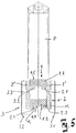
- the guide 2 consists of two, in the longitudinal direction (length L) extending and mutually parallel rails 2 ', 2 "made of plastic, the two aligned upper paragraphs 2.1, 2.2 and two lower facing paragraphs 2.3, 2.4 Paragraphs 2.1, 2.2 form an upper guide strand and the lower paragraphs 2.3, 2.4 form a lower guide strand
- the two rails 2 ', 2 "are fixed to one another via securing means 3.3.
- the upper run 1.1 lies with its underside on the parallel to the conveyor 1 extending paragraphs 2.1, 2.2.
- the lower run 1.2 lies with the visible side 1.5 of the conveyor 1 on the lower shoulders 2.3, 2.4, the angle ⁇ opposite to the conveyor 1 inclined, on.
- the plant of the lower strand 1.2 on the lower guide strand 2.3, 2.4 is linear, such as FIG. 5 can recognize, so that the contact takes place only in the outer area and only there can cause wear.
- the flutter tendency of the lower strand 1.2 is prevented. Due to the inclination of paragraphs 2.3, 2.4 a self-centering in the lower run 1.2 is achieved and thus prevents tarnishing on the side wall.
- the lower run 1.2 can not sag over the length L of the guide 2.
- the angle ⁇ in which the lower paragraphs 2.3, 2.4 are inclined, is selected so that no dirt can settle between the lower strand 1.2 and the guide strand, which could lead to friction on the visible side 1.5 of the conveyor 1. It is between 1 ° and 10 °. An inclination in the angle ⁇ of 3 ° has been found to be positive. In the drawing, the angle ⁇ is exaggerated in order to emphasize the inclination of the lower paragraphs 2.3, 2.4 clearly.
- the guide strand 2 is laterally surrounded by a housing 3, which consists of two housing halves 3.1, 3.2.
- the housing halves 3.1, 3.2 are obliquely angled down so that form wings.
- the guide strand 2 is composed of a plurality of interconnected guide elements 20 together.
- connecting elements 21 are provided which can be inserted in provided in the guide elements 20 grooves.
- the length of the guide strand 2 and thus the number of guide elements 20 is arbitrary and depending on the drive power can be provided.
- a lubricant is provided, which forms only a thin film to prevent wear on the linear contact.
- the upper run 1.1 and the lower run 1.2 should be as close to each other in the flow FV and return FR to keep the space small and thus to increase the efficiency of the conveyor.
- the lower run 1.2 In the area of the two-sided drive wheels 30, the lower run 1.2, however, must be guided further downwards in order to grasp the circumference of the drive wheel 30.
- deflection wheels 40 are provided. These deflecting wheels 40 are grooved over their circumference, such as FIG. 3 shows. Two parallel circumferential grooves, which are not designated here, take plastic rings 41, 42, on which the lower run 1.2 rests with the visible side 1.5.
- the upper run 1.1 lies with its underside over its entire surface in an upper guide 60.
- a guide of the conveying means on the guide 50 which, as FIG. 4 shows in cross-section V-shaped, so that the lower run 1.2 of the conveyor 1 is detected linear again only in its edge region.
Landscapes
- Engineering & Computer Science (AREA)
- Mechanical Engineering (AREA)
- Chain Conveyers (AREA)
- Framework For Endless Conveyors (AREA)
- Belt Conveyors (AREA)
Abstract
Description
- Die Erfindung betrifft eine Fördereinrichtung mit einem endlos umlaufenden Fördermittel, das im Vorlauf ein oberes Trum und im Rücklauf ein unteres Trum ausbildet und dessen zumindest oberes Trum mit seiner Unterseite in einer Führung geführt ist.
- Eine solche Fördereinrichtung ist beispielsweise aus der
DE 40 30 362 A1 bekannt. Bei dieser Fördereinrichtung werden beide Trume seitlich in Schienen geführt. Zur Führung sind in den Kettengliedern Nuten eingebracht, in die die Schienen eingreifen. Insbesondere wenn hohe Fördergeschwindigkeiten realisiert werden müssen und/oder über weite Strecken mit nur einem Fördermittel gefördert werden soll, muss auch das untere Trum geführt werden, damit es nicht durch sein Eigengewicht durchhängt und flattert, was zu Geräuschen und innerem Verschleiß des Fördermittels führt. Hierzu ist jedes Kettenglied mit einer zentralen Längsnut versehen, über das es in einer mittigen Schiene geführt wird. Die Schiene liegt vollflächig in der Längsnut. Durch die Reibung ist Verschleiß unvermeidbar, dieser wird aber drastisch erhöht, wenn die Längsnut, die im oberen Trum offen liegt, verschmutzt. Staub bildet dann, wenn das Kettenglied im unteren Trum läuft, abrasive Partikel. - Der Erfindung liegt die Aufgabe zugrunde, die gattungsgemäße Fördereinrichtung so fortzubilden, dass eine Führung beider Trume möglichst verschleißarm erfolgt.
- Zur Problemlösung zeichnet sich eine gattungsgemäße Fördereinrichtung dadurch aus, dass die Führung mindestens einen oberen Führungsstrang sowie mindestens einen unteren Führungsstrang aufweist und im Querschnitt der Führung der obere Führungsstrang parallel zum Fördermittel und der untere Führungsstrang in einem Winkel geneigt zum Fördermittel verläuft.
- Durch diese Ausgestaltung liegt das obere Trum, auf dessen Sichtseite die Produkte gefördert werden, großflächig auf dem oberen Führungsstrang auf und wird sicher abgestützt. Das untere Trum liegt mit der Sichtseite nach unten im unteren Führungsstrang. Dadurch, dass der untere Führungsstrang zum Fördermittel in einem Winkel geneigt ist, ist das Fördermittel nur im Bereich seiner Längskante in Berührung mit dem Förderstrang, wodurch Flattern und Durchhängen des Fördermittels vermieden wird. Durch die Neigung des unteren Förderstrangs wird verhindert, dass sich Schmutz festsetzen kann und in der Führung abrasive Partikel bildet, sodass ein Verschleiß an der Sichtseite sicher vermieden wird.
- Wenn der Führungsstrang durch in der Führung ausgebildete zwei obere Absätze und zwei untere Absätze gebildet wird, kann dieser zweiteilig ausgeführt werden. Die unteren Absätze sind dann vorzugsweise im Winkel einander entgegengerichtet geneigt. Das untere Trum wird dann beidseitig auf der Sichtseite geführt und liegt in zwei parallelen Linien an dem Führungsstrang an. Hierdurch wird die Führung verbessert und das Flatterverhalten des unteren Trums weiter verbessert. Der durch die Reibung unvermeidbare Verschleiß wird dadurch reduziert, dass das untere Trum nur linienförmig Berührung mit dem Führungsstrang hat. Diese liegt bauartbedingt durch die Neigung der Führung möglichst weit außen, sodass eine Beeinträchtigung der Aufstandsfläche für die Produkte im oberen Trum nicht gegeben ist.
- Der Winkel beträgt vorzugsweise zwischen 1° und 10° und insbesondere zwischen 1° und 3°, weiterhin vorzugsweise 3°. Der Winkel sollte so groß gewählt werden, dass Staub und dergleichen von den Absätzen sicher abgleiten kann, sodass sich keine Schmutzschicht ausbildet, die in Kontakt zu der Sichtseite des Fördermittels gelangt. Durch die zueinander entgegengerichtet geneigten Absätze bildet sich in der Führung ein Kanal aus, in dem bei hoher Fördergeschwindigkeit durch das Zugmittel eine Luftströmung entsteht, die, insbesondere, wenn Wirbel ausgebildet werden, leichte Verschmutzungen von den Absätzen herunterzieht.
- Vorzugsweise ist zwischen dem unteren Trum und dem unteren Führungsstrang ein Schmierfilm vorgesehen, um die Reibung in der Führung zu reduzieren. Durch den Kapillareffekt zieht sich der Schmierfilm über die Sichtseite des Fördermittels und reduziert damit die Reibung zwischen den Produkten und dem Fördermittel.
- Der Führungsstrang kann bevorzugt aus einer Mehrzahl von Führungselementen zusammengesetzt sein, die im Querschnitt identisch ausgebildet sind. Hierzu ist es vorteilhaft, wenn benachbarte Führungselemente über mindestens ein Verbindungselement zueinander zentriert und miteinander verbunden werden. Dann ist eine einfache und ausgerichtete Montage der Führungselemente gewährleistet und eine ebene Führungsfläche sowohl für das obere Trum als auch für das untere Trum erzielbar. Vorsprünge an den Stoßkanten der einzelnen Führungselemente werden dadurch vermieden, weil kein Höhenversatz der Führungselemente vorhanden ist, was einen ruhigen Lauf der Fördereinrichtung gewährleistet und auch den Verschleiß an dem Fördermittel und dem Führungsstrang nicht unnötig erhöht.
- Vorzugsweise besteht die Führung aus Kunststoff und ist in einem sie seitlich umgebenden Gehäuse angeordnet.
- Das Fördermittel kann eine im Raum gelenkige Kette sein, wie sie beispielsweise aus der
EP 0 910 540 B1 oder derWO 94/26636 A1 - Mit Hilfe einer Zeichnung soll ein Ausführungsbeispiel der Erfindung nachfolgend näher beschrieben werden. Es zeigen:
- Figur 1 -
- die Draufsicht auf einen aus zwei parallel laufenden Fördereinrichtungen gebildeten Förderer;
- Figur 2 -
- den Schnitt entlang der Linie II-II nach
Figur 1 ; - Figur 3 -
- den Schnitt entlang der Linie III-III nach
Figur 2 ; - Figur 4 -
- den Schnitt entlang der Linie IV-IV nach
Figur 2 ; - Figur 5 -
- den Schnitt entlang der Line V-V nach
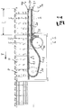
Figur 2 . - Die Fördereinrichtungen 100, 200 sind Teil eines aus mehreren Fördereinrichtungen gebildeten Förderers, auf dem eine Mehrzahl hintereinander angeordneter Produkte P in einer Förderrichtung F gefördert werden. Jede Fördereinrichtung 100, 200 ist separat angetrieben und in der in
Figur 1 dargestellten Anordnung kommen zwei Fördereinrichtungen 100, 200 zusammen und bilden eine Weiche. Die auf der (in der Zeichnung unteren) Fördereinrichtung 100 angelieferten Produkte werden auf die eine kurze Strecke parallel hierzu angeordneten Fördereinrichtung 200 übergeben und dann in Förderrichtung F weitertransportiert. - Das Fördermittel 1, das beispielsweise ein Gurt oder eine Kette ist, wird endlos umlaufend angetrieben und bildet im Vorlauf FV ein oberes Trum 1.1 und im Rücklauf FR ein unteres Trum 1.2 aus, die beide in einer Führung 2 geführt werden. Die Führung 2 besteht aus zwei, sich in Längsrichtung (Länge L) erstreckende und parallel zueinander verlaufenden Schienen 2', 2" aus Kunststoff, die zwei aufeinander zugerichtete obere Absätze 2.1, 2.2 und zwei untere einander zugewandte Absätze 2.3, 2.4 aufweisen. Die oberen Absätze 2.1, 2.2 bilden einen oberen Führungsstrang und die unteren Absätze 2.3, 2.4 einen unteren Führungsstrang aus. Die beiden Schienen 2', 2" sind über Sicherungsmittel 3.3 zueinander fixiert.
- Wie
Figur 5 zeigt, liegt das obere Trum 1.1 mit seiner Unterseite auf den parallel zum Fördermittel 1 verlaufenden Absätzen 2.1, 2.2 auf. Das untere Trum 1.2 liegt mit der Sichtseite 1.5 des Fördermittels 1 auf den unteren Absätzen 2.3, 2.4, die im Winkel α entgegengesetzt gerichtet zum Fördermittel 1 geneigt verlaufen, auf. Die Anlage des unteren Trums 1.2 auf dem unteren Führungsstrang 2.3, 2.4 ist linienförmig, wieFigur 5 erkennen lässt, sodass der Kontakt nur im äußeren Bereich stattfindet und nur dort ein Verschleiß entstehen kann. Die Flatterneigung des unteren Trums 1.2 wird hingegen verhindert. Durch die Neigung der Absätze 2.3, 2.4 wird eine Selbstzentrierung im unteren Trum 1.2 erreicht und somit ein Anlaufen an der Seitenwand verhindert. Auch kann das untere Trum 1.2 über die Länge L der Führung 2 nicht durchhängen. Der Winkel α, in dem die unteren Absätze 2.3, 2.4 geneigt verlaufen, ist so gewählt, dass sich zwischen dem unteren Trum 1.2 und dem Führungsstrang kein Schmutz festsetzen kann, der zur Reibung auf der Sichtseite 1.5 des Fördermittels 1 führen könnte. Er beträgt zwischen 1° und 10°. Eine Neigung im Winkel α von 3° hat sich als positiv herausgestellt. In der Zeichnung ist der Winkel α übertrieben dargestellt, um die Neigung der unteren Absätze 2.3, 2,4 deutlich hervorheben zu können. - Der Führungsstrang 2 wird von einem Gehäuse 3 seitlich umgeben, das aus zwei Gehäusehälften 3.1, 3.2 besteht. Die Gehäusehälften 3.1, 3.2 sind unten schräg abgewinkelt, sodass sich Flügel ausbilden. Der Führungsstrang 2 setzt sich aus mehreren miteinander verbundenen Führungselementen 20 zusammen. Zur Verbindung und Zentrierung benachbarter Führungselemente 20 sind Verbindungselemente 21 vorgesehen, die in in den Führungselementen 20 vorgesehenen Nuten eingesteckt werden können. Die Länge des Führungsstranges 2 und damit die Anzahl der Führungselemente 20 ist beliebig und abhängig von der Antriebsleistung die zur Verfügung gestellt werden kann.
- Zwischen der Sichtseite 1.5 des unteren Trums 1.2 und dem unteren Führungsstrang 2.3, 2.4 ist ein Schmiermittel vorgesehen, das nur einen dünnen Film ausbildet, um Verschleiß an der linienförmigen Berührung zu vermeiden.
- Das obere Trum 1.1 und das untere Trum 1.2 sollten möglichst dicht beieinander im Vorlauf FV und Rücklauf FR sein, um den Bauraum klein zu halten und auch damit den Wirkungsgrad der Fördereinrichtung zu erhöhen. Im Bereich der beidseitigen Antriebsräder 30 muss das untere Trum 1.2 aber weiter nach unten geführt werden, um den Umfang des Antriebsrades 30 zu erfassen. Hierzu sind Umlenkräder 40 vorgesehen. Diese Umlenkräder 40 sind über ihren Umfang ausgekehlt, wie
Figur 3 zeigt. Zwei parallele Umfangsnuten, die hier nicht näher bezeichnet sind, nehmen Kunststoffringe 41, 42 auf, auf denen das untere Trum 1.2 mit der Sichtseite 1.5 aufliegt. Durch die Rundung der Ringe 41, 42 und der planen Sichtseite 1.5 wird das untere Trum 1.2 nur an zwei Punkten berührt, wodurch der Verschleiß an der Sichtseite 1.5 ebenfalls minimiert ist. Das obere Trum 1.1 liegt mit seiner Unterseite vollflächig in einer oberen Führung 60 auf. Im weiteren Verlauf erfolgt dann an der Übergabestelle zwischen dem Umlenkrad 40 und dem Führungselement 20 eine Führung des Fördermittels über die Führung 50, die, wieFigur 4 zeigt im Querschnitt V-förmig ausgebildet ist, sodass das untere Trum 1.2 des Fördermittels 1 wieder nur in seinem Randbereich linienförmig erfasst wird. -
- 1
- Fördermittel
- 1.1
- oberes Trum
- 1.2
- unteres Trum
- 1.5
- Sichtseite
- 2
- Führung
- 2.1
- Führungsstrang/oberer Absatz
- 2.2
- Führungsstrang/oberer Absatz
- 2.3
- Führungsstrang/unterer Absatz
- 2.4
- Führungsstrang/unterer Absatz
- 2'
- Schiene
- 2"
- Schiene
- 3
- Gehäuse
- 3.1
- Gehäuse
- 3.2
- Gehäuse
- 3.3
- Sicherungsmittel
- 20
- Führungselement
- 21
- Verbindungselement
- 30
- Antriebsrad
- 40
- Umlenkrad
- 41
- Ring
- 42
- Ring
- 50
- Führung
- 60
- Führung
- 100
- Fördereinrichtung
- 200
- Fördereinrichtung
- α
- Winkel
- F
- Förderrichtung
- FR
- Rücklauf
- FV
- Vorlauf
- L
- Länge
- P
- Produkt
Claims (11)
- Fördereinrichtung mit einem endlos umlaufenden Fördermittel (1), das im Vorlauf (FV) ein oberes Trum (1.1) und im Rücklauf (FR) ein unteres Trum (1.2) ausbildet und dessen zumindest oberes Trum (1.1) mit seiner Unterseite in einer Führung (2) geführt ist, dadurch gekennzeichnet, dass die Führung (2) mindestens einen oberen Führungsstrang (2.1, 2.2) sowie min-destens einen unteren Führungsstrang (2.3, 2.4) aufweist und im Querschnitt der Führung (2) der obere Führungsstrang (2.1, 2.2) parallel zum Fördermittel (1) und der untere Führungsstrang (2.3, 2.4) in einem Winkel (α) geneigt zum Fördermittel (1) verläuft.
- Fördereinrichtung nach Anspruch 1,
dadurch gekennzeichnet, dass
jeder Führungsstrang durch in der Führung (2) ausgebildete zwei obere Absät-ze (2.1, 2.2) und zwei untere Absätze (2.3, 2.4) gebildet wird. - Fördereinrichtung nach Anspruch 2,
dadurch gekennzeichnet, dass
die beiden Absätze (2.1, 2.2; 2.3, 2.4) sich jeweils gegenüberliegen. - Fördereinrichtung nach Anspruch 3,
dadurch gekennzeichnet, dass
die unteren Absätze (2.3, 2.4) im Winkel (α) einander entgegengerichtet geneigt sind. - Fördereinrichtung nach einem der vorstehenden Ansprüche,
dadurch gekennzeichnet, dass
dass der Winkel (α) zwischen 1° und 10° beträgt. - Fördereinrichtung nach Anspruch 5,
dadurch gekennzeichnet, dass
der Winkel (α) zwischen 1°und 3°, vorzugsweise 3° beträgt. - Fördereinrichtung nach einem der vorstehenden Ansprüche,
dadurch gekennzeichnet, dass
zwischen dem unteren Trum (1.2) und dem unteren Führungsstrang (2.3, 2.4) ein Schmierfilm vorgesehen ist. - Fördereinrichtung nach einem der vorstehenden Ansprüche,
dadurch gekennzeichnet, dass
die Führung (2) aus einer Mehrzahl von Führungsele-menten (20) zusammengesetzt ist, die im Querschnitt identisch ausgebildet sind. - Fördereinrichtung nach Anspruch 8,
dadurch gekennzeichnet, dass
benachbarte Führungselemente (20) über mindestens ein Verbindungselement (21) zueinander zentriert und miteinander verbunden werden. - Fördereinrichtung nach einem der vorstehenden Ansprüche,
dadurch gekennzeichnet, dass
die Führung (2) aus Kunststoff besteht und in einem sie seitlich umgebenden Gehäuse (3) angeordnet ist. - Fördereinrichtung nach einem der vorstehenden Ansprüche,
dadurch gekennzeichnet, dass
das Fördermittel (1) ein Kette oder ein Riemen ist.
Applications Claiming Priority (1)
| Application Number | Priority Date | Filing Date | Title |
|---|---|---|---|
| DE102016104768.6A DE102016104768A1 (de) | 2016-03-15 | 2016-03-15 | Fördereinrichtung |
Publications (2)
| Publication Number | Publication Date |
|---|---|
| EP3219645A1 true EP3219645A1 (de) | 2017-09-20 |
| EP3219645B1 EP3219645B1 (de) | 2021-12-15 |
Family
ID=58192153
Family Applications (1)
| Application Number | Title | Priority Date | Filing Date |
|---|---|---|---|
| EP17158303.2A Active EP3219645B1 (de) | 2016-03-15 | 2017-02-28 | Fördereinrichtung mit geneigtem führungsstrang |
Country Status (5)
| Country | Link |
|---|---|
| EP (1) | EP3219645B1 (de) |
| CN (1) | CN107352223B (de) |
| BR (1) | BR202017004878Y1 (de) |
| DE (1) | DE102016104768A1 (de) |
| ES (1) | ES2908781T3 (de) |
Cited By (1)
| Publication number | Priority date | Publication date | Assignee | Title |
|---|---|---|---|---|
| WO2022189323A1 (en) * | 2021-03-08 | 2022-09-15 | Marel A/S | A conveyor system |
Citations (7)
| Publication number | Priority date | Publication date | Assignee | Title |
|---|---|---|---|---|
| DE3619949C1 (en) * | 1986-06-13 | 1987-07-02 | Halbach & Braun Ind Anlagen | Impact roller crusher |
| DE4030362A1 (de) | 1990-09-26 | 1992-04-02 | Tetra Pak Gmbh | Foerdereinrichtung fuer werkstuecktraeger |
| WO1992011191A1 (en) * | 1990-12-20 | 1992-07-09 | Ideas In Motion Pty. Ltd. | Modular conveyor system |
| WO1994026636A1 (en) | 1993-05-13 | 1994-11-24 | Wahren Mats | Device at a conveyor chain |
| EP0910540B1 (de) | 1996-04-25 | 2000-08-16 | David John Cockayne | Verbesserungen in, oder in bezug auf montageanlage-systeme |
| US6848572B1 (en) * | 2003-11-10 | 2005-02-01 | Danville Automation Holdings Llc | Modular conveyor system |
| DE102015106096A1 (de) * | 2015-04-21 | 2016-10-27 | Halbach & Braun Industrieanlagen Gmbh & Co. | Fördersystem für Schüttgüter |
Family Cites Families (6)
| Publication number | Priority date | Publication date | Assignee | Title |
|---|---|---|---|---|
| GB1417993A (en) * | 1972-07-12 | 1975-12-17 | Britton J | Belt conveyors |
| JP5176223B2 (ja) * | 2006-07-04 | 2013-04-03 | インベンテイオ・アクテイエンゲゼルシヤフト | 乗客輸送装置用の駆動システム |
| JP4522463B2 (ja) * | 2008-04-21 | 2010-08-11 | 株式会社アイディエス | 検体搬送装置及び検体処理装置 |
| DE102011017525A1 (de) * | 2011-04-26 | 2012-10-31 | Robert Bosch Gmbh | Transportsystem mit Schleusenvorrichtung |
| DE102013112827A1 (de) * | 2013-11-20 | 2015-05-21 | Manroland Web Systems Gmbh | Führung für ein Transportband in einer Druckmaschine |
| DE102014222459A1 (de) * | 2014-11-04 | 2016-05-04 | Robert Bosch Gmbh | Fördermodul mit gegossener Umlenkbaugruppe |
-
2016
- 2016-03-15 DE DE102016104768.6A patent/DE102016104768A1/de not_active Withdrawn
-
2017
- 2017-02-28 ES ES17158303T patent/ES2908781T3/es active Active
- 2017-02-28 EP EP17158303.2A patent/EP3219645B1/de active Active
- 2017-03-10 BR BR202017004878-6U patent/BR202017004878Y1/pt active IP Right Grant
- 2017-03-13 CN CN201710145730.4A patent/CN107352223B/zh active Active
Patent Citations (7)
| Publication number | Priority date | Publication date | Assignee | Title |
|---|---|---|---|---|
| DE3619949C1 (en) * | 1986-06-13 | 1987-07-02 | Halbach & Braun Ind Anlagen | Impact roller crusher |
| DE4030362A1 (de) | 1990-09-26 | 1992-04-02 | Tetra Pak Gmbh | Foerdereinrichtung fuer werkstuecktraeger |
| WO1992011191A1 (en) * | 1990-12-20 | 1992-07-09 | Ideas In Motion Pty. Ltd. | Modular conveyor system |
| WO1994026636A1 (en) | 1993-05-13 | 1994-11-24 | Wahren Mats | Device at a conveyor chain |
| EP0910540B1 (de) | 1996-04-25 | 2000-08-16 | David John Cockayne | Verbesserungen in, oder in bezug auf montageanlage-systeme |
| US6848572B1 (en) * | 2003-11-10 | 2005-02-01 | Danville Automation Holdings Llc | Modular conveyor system |
| DE102015106096A1 (de) * | 2015-04-21 | 2016-10-27 | Halbach & Braun Industrieanlagen Gmbh & Co. | Fördersystem für Schüttgüter |
Cited By (2)
| Publication number | Priority date | Publication date | Assignee | Title |
|---|---|---|---|---|
| WO2022189323A1 (en) * | 2021-03-08 | 2022-09-15 | Marel A/S | A conveyor system |
| US12006153B2 (en) | 2021-03-08 | 2024-06-11 | Marel A/S | Conveyor system |
Also Published As
| Publication number | Publication date |
|---|---|
| CN107352223A (zh) | 2017-11-17 |
| EP3219645B1 (de) | 2021-12-15 |
| ES2908781T3 (es) | 2022-05-03 |
| BR202017004878U2 (pt) | 2017-10-10 |
| CN107352223B (zh) | 2021-10-29 |
| BR202017004878Y1 (pt) | 2022-04-26 |
| DE102016104768A1 (de) | 2017-09-21 |
Similar Documents
| Publication | Publication Date | Title |
|---|---|---|
| EP2560905B1 (de) | Transportvorrichtung mit verbesserten laufeigenschaften | |
| EP3449152B1 (de) | Antriebsband-verbindungseinrichtung, eingerichtet zur zugfesten verbindung von flachen antriebsband-endabschnitten, antriebsband und damit ausgestattete fördereinrichtung | |
| EP2921435A1 (de) | Umlenkvorrichtung für Gegenstände und Verfahren zum Umlenken von Gegenständen | |
| EP2060512B1 (de) | Anlage zur Förderung von Gütern | |
| EP2679522A1 (de) | Transportbandelement zum Transportieren von Gütern, Verfahren zum Führen eines Transportbandelements und Anordnung aus einem Transportbandelement und einer Umlenk- und/oder Antriebswalzenvorrichtung | |
| WO2018077670A1 (de) | Fördersystem | |
| WO2008095572A1 (de) | Kettenrad für kettenantriebe und kettenkratzerförderer | |
| WO2003020617A1 (de) | Staufähiges kurvenelement für ein transfersystem | |
| WO2012068694A1 (de) | Fördersystem, förderelement und führungsbahn | |
| EP1084070B1 (de) | Transportkette | |
| EP3219645B1 (de) | Fördereinrichtung mit geneigtem führungsstrang | |
| DE4041587C2 (de) | ||
| EP3498639A1 (de) | Vorrichtung zum zusammenführen von zwei in unterschiedlichen höhen angeordneten stückgutströmen | |
| EP3033217B1 (de) | Umlenkvorrichtung für eine kette aus spannkluppen mit laufrollen zum transport einer bewegten materialbahn | |
| DE102014102873A1 (de) | Förderer zum Sortieren von Stückgütern | |
| EP3044132A1 (de) | Transportrad sowie transportsystem | |
| DE102017011293A1 (de) | Laufbahn, Fördereinrichtung und Verfahren zur Montage einer Laufbahn | |
| EP0139287A2 (de) | Stetigförderer | |
| DE10162850A1 (de) | Transportkette | |
| DE10239819B4 (de) | Vorrichtung zum Spannen eines flexiblen Fördermittels | |
| DE10208303B4 (de) | Fördersystem zum Transport von Stückgütern | |
| WO2014037095A1 (de) | Vorrichtung und verfahren zum reinigen einer förderkette | |
| DE20104463U1 (de) | Plattenförderer zum Bewegen von Lasten | |
| DE3820269A1 (de) | Baugruppe zum foerdern eines produktstromes von papierprodukten mit einem einzigen foerderbandpaarsystem | |
| DE4335862C2 (de) | Umlenkelement zum Umlenken von Staurollenketten |
Legal Events
| Date | Code | Title | Description |
|---|---|---|---|
| PUAI | Public reference made under article 153(3) epc to a published international application that has entered the european phase |
Free format text: ORIGINAL CODE: 0009012 |
|
| STAA | Information on the status of an ep patent application or granted ep patent |
Free format text: STATUS: REQUEST FOR EXAMINATION WAS MADE |
|
| 17P | Request for examination filed |
Effective date: 20170228 |
|
| AK | Designated contracting states |
Kind code of ref document: A1 Designated state(s): AL AT BE BG CH CY CZ DE DK EE ES FI FR GB GR HR HU IE IS IT LI LT LU LV MC MK MT NL NO PL PT RO RS SE SI SK SM TR |
|
| AX | Request for extension of the european patent |
Extension state: BA ME |
|
| RAP1 | Party data changed (applicant data changed or rights of an application transferred) |
Owner name: ILLINOIS TOOL WORKS, INC. |
|
| GRAP | Despatch of communication of intention to grant a patent |
Free format text: ORIGINAL CODE: EPIDOSNIGR1 |
|
| STAA | Information on the status of an ep patent application or granted ep patent |
Free format text: STATUS: GRANT OF PATENT IS INTENDED |
|
| INTG | Intention to grant announced |
Effective date: 20210630 |
|
| GRAS | Grant fee paid |
Free format text: ORIGINAL CODE: EPIDOSNIGR3 |
|
| GRAA | (expected) grant |
Free format text: ORIGINAL CODE: 0009210 |
|
| STAA | Information on the status of an ep patent application or granted ep patent |
Free format text: STATUS: THE PATENT HAS BEEN GRANTED |
|
| AK | Designated contracting states |
Kind code of ref document: B1 Designated state(s): AL AT BE BG CH CY CZ DE DK EE ES FI FR GB GR HR HU IE IS IT LI LT LU LV MC MK MT NL NO PL PT RO RS SE SI SK SM TR |
|
| REG | Reference to a national code |
Ref country code: GB Ref legal event code: FG4D Free format text: NOT ENGLISH Ref country code: CH Ref legal event code: EP |
|
| REG | Reference to a national code |
Ref country code: DE Ref legal event code: R096 Ref document number: 502017012228 Country of ref document: DE |
|
| REG | Reference to a national code |
Ref country code: IE Ref legal event code: FG4D Free format text: LANGUAGE OF EP DOCUMENT: GERMAN |
|
| REG | Reference to a national code |
Ref country code: AT Ref legal event code: REF Ref document number: 1455351 Country of ref document: AT Kind code of ref document: T Effective date: 20220115 |
|
| REG | Reference to a national code |
Ref country code: NL Ref legal event code: FP |
|
| REG | Reference to a national code |
Ref country code: LT Ref legal event code: MG9D |
|
| PG25 | Lapsed in a contracting state [announced via postgrant information from national office to epo] |
Ref country code: RS Free format text: LAPSE BECAUSE OF FAILURE TO SUBMIT A TRANSLATION OF THE DESCRIPTION OR TO PAY THE FEE WITHIN THE PRESCRIBED TIME-LIMIT Effective date: 20211215 Ref country code: LT Free format text: LAPSE BECAUSE OF FAILURE TO SUBMIT A TRANSLATION OF THE DESCRIPTION OR TO PAY THE FEE WITHIN THE PRESCRIBED TIME-LIMIT Effective date: 20211215 Ref country code: FI Free format text: LAPSE BECAUSE OF FAILURE TO SUBMIT A TRANSLATION OF THE DESCRIPTION OR TO PAY THE FEE WITHIN THE PRESCRIBED TIME-LIMIT Effective date: 20211215 Ref country code: BG Free format text: LAPSE BECAUSE OF FAILURE TO SUBMIT A TRANSLATION OF THE DESCRIPTION OR TO PAY THE FEE WITHIN THE PRESCRIBED TIME-LIMIT Effective date: 20220315 |
|
| REG | Reference to a national code |
Ref country code: ES Ref legal event code: FG2A Ref document number: 2908781 Country of ref document: ES Kind code of ref document: T3 Effective date: 20220503 |
|
| PG25 | Lapsed in a contracting state [announced via postgrant information from national office to epo] |
Ref country code: SE Free format text: LAPSE BECAUSE OF FAILURE TO SUBMIT A TRANSLATION OF THE DESCRIPTION OR TO PAY THE FEE WITHIN THE PRESCRIBED TIME-LIMIT Effective date: 20211215 Ref country code: NO Free format text: LAPSE BECAUSE OF FAILURE TO SUBMIT A TRANSLATION OF THE DESCRIPTION OR TO PAY THE FEE WITHIN THE PRESCRIBED TIME-LIMIT Effective date: 20220315 Ref country code: LV Free format text: LAPSE BECAUSE OF FAILURE TO SUBMIT A TRANSLATION OF THE DESCRIPTION OR TO PAY THE FEE WITHIN THE PRESCRIBED TIME-LIMIT Effective date: 20211215 Ref country code: HR Free format text: LAPSE BECAUSE OF FAILURE TO SUBMIT A TRANSLATION OF THE DESCRIPTION OR TO PAY THE FEE WITHIN THE PRESCRIBED TIME-LIMIT Effective date: 20211215 Ref country code: GR Free format text: LAPSE BECAUSE OF FAILURE TO SUBMIT A TRANSLATION OF THE DESCRIPTION OR TO PAY THE FEE WITHIN THE PRESCRIBED TIME-LIMIT Effective date: 20220316 |
|
| PG25 | Lapsed in a contracting state [announced via postgrant information from national office to epo] |
Ref country code: SM Free format text: LAPSE BECAUSE OF FAILURE TO SUBMIT A TRANSLATION OF THE DESCRIPTION OR TO PAY THE FEE WITHIN THE PRESCRIBED TIME-LIMIT Effective date: 20211215 Ref country code: SK Free format text: LAPSE BECAUSE OF FAILURE TO SUBMIT A TRANSLATION OF THE DESCRIPTION OR TO PAY THE FEE WITHIN THE PRESCRIBED TIME-LIMIT Effective date: 20211215 Ref country code: RO Free format text: LAPSE BECAUSE OF FAILURE TO SUBMIT A TRANSLATION OF THE DESCRIPTION OR TO PAY THE FEE WITHIN THE PRESCRIBED TIME-LIMIT Effective date: 20211215 Ref country code: PT Free format text: LAPSE BECAUSE OF FAILURE TO SUBMIT A TRANSLATION OF THE DESCRIPTION OR TO PAY THE FEE WITHIN THE PRESCRIBED TIME-LIMIT Effective date: 20220418 Ref country code: EE Free format text: LAPSE BECAUSE OF FAILURE TO SUBMIT A TRANSLATION OF THE DESCRIPTION OR TO PAY THE FEE WITHIN THE PRESCRIBED TIME-LIMIT Effective date: 20211215 Ref country code: CZ Free format text: LAPSE BECAUSE OF FAILURE TO SUBMIT A TRANSLATION OF THE DESCRIPTION OR TO PAY THE FEE WITHIN THE PRESCRIBED TIME-LIMIT Effective date: 20211215 |
|
| PG25 | Lapsed in a contracting state [announced via postgrant information from national office to epo] |
Ref country code: PL Free format text: LAPSE BECAUSE OF FAILURE TO SUBMIT A TRANSLATION OF THE DESCRIPTION OR TO PAY THE FEE WITHIN THE PRESCRIBED TIME-LIMIT Effective date: 20211215 |
|
| REG | Reference to a national code |
Ref country code: DE Ref legal event code: R097 Ref document number: 502017012228 Country of ref document: DE |
|
| PG25 | Lapsed in a contracting state [announced via postgrant information from national office to epo] |
Ref country code: MC Free format text: LAPSE BECAUSE OF FAILURE TO SUBMIT A TRANSLATION OF THE DESCRIPTION OR TO PAY THE FEE WITHIN THE PRESCRIBED TIME-LIMIT Effective date: 20211215 Ref country code: IS Free format text: LAPSE BECAUSE OF FAILURE TO SUBMIT A TRANSLATION OF THE DESCRIPTION OR TO PAY THE FEE WITHIN THE PRESCRIBED TIME-LIMIT Effective date: 20220415 |
|
| REG | Reference to a national code |
Ref country code: CH Ref legal event code: PL |
|
| PLBE | No opposition filed within time limit |
Free format text: ORIGINAL CODE: 0009261 |
|
| STAA | Information on the status of an ep patent application or granted ep patent |
Free format text: STATUS: NO OPPOSITION FILED WITHIN TIME LIMIT |
|
| REG | Reference to a national code |
Ref country code: BE Ref legal event code: MM Effective date: 20220228 |
|
| PG25 | Lapsed in a contracting state [announced via postgrant information from national office to epo] |
Ref country code: LU Free format text: LAPSE BECAUSE OF NON-PAYMENT OF DUE FEES Effective date: 20220228 Ref country code: DK Free format text: LAPSE BECAUSE OF FAILURE TO SUBMIT A TRANSLATION OF THE DESCRIPTION OR TO PAY THE FEE WITHIN THE PRESCRIBED TIME-LIMIT Effective date: 20211215 Ref country code: AL Free format text: LAPSE BECAUSE OF FAILURE TO SUBMIT A TRANSLATION OF THE DESCRIPTION OR TO PAY THE FEE WITHIN THE PRESCRIBED TIME-LIMIT Effective date: 20211215 |
|
| 26N | No opposition filed |
Effective date: 20220916 |
|
| PG25 | Lapsed in a contracting state [announced via postgrant information from national office to epo] |
Ref country code: SI Free format text: LAPSE BECAUSE OF FAILURE TO SUBMIT A TRANSLATION OF THE DESCRIPTION OR TO PAY THE FEE WITHIN THE PRESCRIBED TIME-LIMIT Effective date: 20211215 |
|
| PG25 | Lapsed in a contracting state [announced via postgrant information from national office to epo] |
Ref country code: LI Free format text: LAPSE BECAUSE OF NON-PAYMENT OF DUE FEES Effective date: 20220228 Ref country code: IE Free format text: LAPSE BECAUSE OF NON-PAYMENT OF DUE FEES Effective date: 20220228 Ref country code: CH Free format text: LAPSE BECAUSE OF NON-PAYMENT OF DUE FEES Effective date: 20220228 |
|
| PG25 | Lapsed in a contracting state [announced via postgrant information from national office to epo] |
Ref country code: BE Free format text: LAPSE BECAUSE OF NON-PAYMENT OF DUE FEES Effective date: 20220228 |
|
| REG | Reference to a national code |
Ref country code: AT Ref legal event code: MM01 Ref document number: 1455351 Country of ref document: AT Kind code of ref document: T Effective date: 20220228 |
|
| PG25 | Lapsed in a contracting state [announced via postgrant information from national office to epo] |
Ref country code: AT Free format text: LAPSE BECAUSE OF NON-PAYMENT OF DUE FEES Effective date: 20220228 |
|
| P01 | Opt-out of the competence of the unified patent court (upc) registered |
Effective date: 20230606 |
|
| PG25 | Lapsed in a contracting state [announced via postgrant information from national office to epo] |
Ref country code: HU Free format text: LAPSE BECAUSE OF FAILURE TO SUBMIT A TRANSLATION OF THE DESCRIPTION OR TO PAY THE FEE WITHIN THE PRESCRIBED TIME-LIMIT; INVALID AB INITIO Effective date: 20170228 |
|
| PG25 | Lapsed in a contracting state [announced via postgrant information from national office to epo] |
Ref country code: MK Free format text: LAPSE BECAUSE OF FAILURE TO SUBMIT A TRANSLATION OF THE DESCRIPTION OR TO PAY THE FEE WITHIN THE PRESCRIBED TIME-LIMIT Effective date: 20211215 Ref country code: CY Free format text: LAPSE BECAUSE OF FAILURE TO SUBMIT A TRANSLATION OF THE DESCRIPTION OR TO PAY THE FEE WITHIN THE PRESCRIBED TIME-LIMIT Effective date: 20211215 |
|
| PG25 | Lapsed in a contracting state [announced via postgrant information from national office to epo] |
Ref country code: TR Free format text: LAPSE BECAUSE OF FAILURE TO SUBMIT A TRANSLATION OF THE DESCRIPTION OR TO PAY THE FEE WITHIN THE PRESCRIBED TIME-LIMIT Effective date: 20211215 |
|
| PG25 | Lapsed in a contracting state [announced via postgrant information from national office to epo] |
Ref country code: MT Free format text: LAPSE BECAUSE OF FAILURE TO SUBMIT A TRANSLATION OF THE DESCRIPTION OR TO PAY THE FEE WITHIN THE PRESCRIBED TIME-LIMIT Effective date: 20211215 |
|
| PGFP | Annual fee paid to national office [announced via postgrant information from national office to epo] |
Ref country code: NL Payment date: 20260226 Year of fee payment: 10 |
|
| PGFP | Annual fee paid to national office [announced via postgrant information from national office to epo] |
Ref country code: GB Payment date: 20260227 Year of fee payment: 10 |
|
| PGFP | Annual fee paid to national office [announced via postgrant information from national office to epo] |
Ref country code: ES Payment date: 20260302 Year of fee payment: 10 |
|
| PGFP | Annual fee paid to national office [announced via postgrant information from national office to epo] |
Ref country code: DE Payment date: 20260227 Year of fee payment: 10 |
|
| PGFP | Annual fee paid to national office [announced via postgrant information from national office to epo] |
Ref country code: IT Payment date: 20260219 Year of fee payment: 10 |
|
| PGFP | Annual fee paid to national office [announced via postgrant information from national office to epo] |
Ref country code: FR Payment date: 20260225 Year of fee payment: 10 |