EP3219864A1 - Soupape de vidange pur un récipient de liquide, récipient de liquide destiné à produire une vague de lavage et procédé de production d'une vague de lavage - Google Patents
Soupape de vidange pur un récipient de liquide, récipient de liquide destiné à produire une vague de lavage et procédé de production d'une vague de lavage Download PDFInfo
- Publication number
- EP3219864A1 EP3219864A1 EP17156476.8A EP17156476A EP3219864A1 EP 3219864 A1 EP3219864 A1 EP 3219864A1 EP 17156476 A EP17156476 A EP 17156476A EP 3219864 A1 EP3219864 A1 EP 3219864A1
- Authority
- EP
- European Patent Office
- Prior art keywords
- riser
- liquid
- float
- liquid container
- valve
- Prior art date
- Legal status (The legal status is an assumption and is not a legal conclusion. Google has not performed a legal analysis and makes no representation as to the accuracy of the status listed.)
- Granted
Links
Images



Classifications
-
- E—FIXED CONSTRUCTIONS
- E03—WATER SUPPLY; SEWERAGE
- E03F—SEWERS; CESSPOOLS
- E03F5/00—Sewerage structures
- E03F5/10—Collecting-tanks; Equalising-tanks for regulating the run-off; Laying-up basins
- E03F5/105—Accessories, e.g. flow regulators or cleaning devices
- E03F5/108—Cleaning devices providing a flushing surge
-
- E—FIXED CONSTRUCTIONS
- E03—WATER SUPPLY; SEWERAGE
- E03F—SEWERS; CESSPOOLS
- E03F9/00—Arrangements or fixed installations methods or devices for cleaning or clearing sewer pipes, e.g. by flushing
- E03F9/007—Devices providing a flushing surge
-
- E—FIXED CONSTRUCTIONS
- E03—WATER SUPPLY; SEWERAGE
- E03F—SEWERS; CESSPOOLS
- E03F2201/00—Details, devices or methods not otherwise provided for
- E03F2201/30—Devices providing a sequential discharge in sewer systems
Definitions
- the present invention relates to a drain valve for shutting off a drain opening of a liquid container according to the preambles of claims 1 and 2, a liquid container for generating a flushing surge according to claim 11 and a method for generating a flushing surge, preferably for a sewer system according to the preamble of claim 12.
- a method for surge flushing of a mixed water channel and a device for this purpose in which at least two successive, mutually lockable sections are provided in an underground sewer.
- the upstream portion is sealed off against the downstream portion and then, after reaching a predetermined damming height in the upstream portion of the mixed water channel the abutment is released abruptly.
- subterranean, motor-driven Abschottklappen are provided in the mixed water channel, which provided by an above-ground control and Power supply unit to be actuated.
- the level measurement for determining the damming height is performed with ultrasound probes. This is what the design in the DE 100 10 836 A1 described concept very technically complicated.
- the control mechanism has a latch actuated by a floated lever.
- a buoyancy body is arranged, which floats in the dammed wastewater and thus actuates the parallel lever for transferring the Spülschildes in an open position.
- electrical components can be dispensed with, and the surge flushing device can be arranged as a whole underground within the channel, so that overall the construction is considerably simplified with respect to the device described first.
- the two devices described above nevertheless have the disadvantage that they must be arranged within the underground sewer, which makes maintenance and installation very difficult.
- the storage level is limited within the sewer, so that the strength of the flushing surge is also subject to narrow limits and depending on the length of the dammed channel section and a large amount of water to carry out the flushing surge may be required.
- Kanal confusevorettivotechnische that can be located above or outside the actual sewer. These are even operated above ground preferably with surface waters. Surface waters usually contain less solids and high viscosity fractions than the wastewater mixtures carried in the sewer itself.
- the aforementioned closure body is designed as a rubber or plastic ball that must fit tightly into a seat formed by the flushing opening and the flood opening. Furthermore, the entire device has a total of three different floats and is structurally so complex that the production of the channel flush is relatively expensive and expensive.
- a sewer cleaner for cleaning a drainage channel for rain or mixed water in a flushing well, in which two separate floats are provided on a central support tube, as well as two separate shut-off devices for closing the drainage opening, which are described in the form of a VerInstituttellers and a sealing element.
- an overflow pipe is provided, through which, when a certain flushing shaft level is exceeded, water runs into a sealable filling zone, which gradually fills up.
- One of the two floats opens both shut-off valves simultaneously when the water level in the filling zone rises.
- the sealing element is closed again by lowering the first float.
- the closure is closed again by the second float with increasing level in the Spülschacht, the second float is connected via a lever linkage with the closure plate.
- the invention has for its object to provide a further simplified and cheaper Schwall Suitevortechnische.
- drain valves for shutting off a drain opening of a liquid container according to claim 1 or 2, by a liquid container according to claim 11 and by a method for generating a flushing surge, preferably for a sewer system, according to claim 12.
- the drain valve according to claim 1 for shutting off a drain opening of a liquid container, a riser, in which liquid can rise.
- a riser in which liquid can rise.
- a trained as a float valve member is taken, which floats on entry of liquid into the riser and rises from its closing position closing the drain opening in an open position.
- a ventilation device is provided which selectively blocks or releases a vent opening of the riser, so that an air cushion, which forms in a space adjacent to the vent opening space within the riser, is released from the riser and liquid can suddenly enter the riser.
- the invention is particularly characterized in that the valve member is at least partially disposed in the riser.
- the drain valve according to claim 2 has to shut off a drain opening of a liquid container to a riser, in which liquid can rise.
- a float is arranged, which floats on entry of liquid into the riser.
- a valve member is guided in the riser, which is movable between an open position and a closed position and which is entrained by the float from the closed position to the open position.
- these drain valves are characterized by the fact that a ventilation device is provided which selectively blocks and releases a vent opening of the riser, so that an air cushion, which forms in a space adjacent to the vent opening space when floating the float is discharged from the riser and Liquid can enter the riser.
- the float located therein floats and takes the guided in the riser valve member with in the open position.
- the invention is based on the technical principle that the enclosed in the riser air cushion is under an at least slight overpressure relative to the environment, so that when you open the venting the air cushion from the Rising tube can escape quickly and rising in the riser liquid level together with the floater located in the riser abruptly moves into the open position.
- valve member is actuated on the one hand by the liquid level, as soon as only the vent opening of the riser is released. This allows a very simple and robust construction of the drain valve.
- the float protrudes in the closed position into the room. This allows a simple and safe guidance of the float in the actuation path.
- the venting device releases the vent opening as a function of a liquid level surrounding the riser pipe.
- the drain valve within the liquid container which may be a Spülschacht, is arranged, whereby the required space is significantly reduced.
- the riser is not only in fluid communication with the liquid level in the liquid container. Rather, the rising liquid level in the liquid container can be used to actuate the venting device. In this way, the drain valve works automatically and reliably.
- the venting device is float-controlled. This is a very simple way to use the rising liquid level to operate the vent. Compared with other types of operation, such as an electric or pneumatic actuation, such a design has significant cost advantages and works with a higher reliability.
- the venting device has a shut-off, which closes the vent opening in the blocking position.
- the venting device with particularly simple means to implement and works extremely reliable.
- a cover resting on the vent opening can be provided here, which closes the vent opening in blocking position.
- the shut-off element is designed floatable or connected to a float.
- a float which are especially simple Possibilities to design the venting device, as it can actuate itself by the increase of the liquid level.
- the cover resting on the vent opening itself is floatable, ie, designed as a float, and thus combines the control function, the actuation function and the shut-off function of the venting device in a single component.
- the shut-off element is connected to a float, which in turn consists either of a buoyant material or is designed as a floating body.
- the float may be formed as an inverted cup, which encloses an air cushion with increasing liquid level.
- the shut-off element has a sealing portion with which the vent opening can be closed. This can improve the sealing function of the shut-off element for closing the vent opening, since the specially designed sealing section is adapted to the vent opening in order to close it in a targeted and reliable manner.
- a guide is provided on the riser pipe or the shut-off .
- a guide has the purpose to guide the shut-off element along its actuating path between the locking position and the release position, so that a more reliable function can be ensured.
- the trained as a float valve body is designed as a hollow body. Manufacturing technology, the use of a hollow body has been found to be particularly advantageous.
- the hollow body for adjusting the density of the float can be filled with ballast, whereby the opening and closing behavior of the designed as a float valve body can be targeted.
- a pressure compensation device for the preparation of a pressure equalization between the vent opening facing top and the drain opening facing the bottom of the valve member is provided.
- a more reliable function of the float can be ensured in conjunction with the valve member to compensate for flow-related effects that oppose the driving movement of the float for opening the valve member. It has been shown here that the Drain valve even more reliable when the said pressure equalization is established during the transfer of the valve member in its open position.
- the pressure compensation device comprises a pressure equalization channel and a check valve.
- a pressure equalization channel which preferably extends between the two ends of the valve member, is a very simple way to establish pressure equalization.
- the check valve is provided, which strives under the built-up in the riser pressure of the air cushion in the closed position.
- the non-return valve has the purpose to compensate for any occurring pressure peaks during the expiring rinsing surge and to keep the valve member longer in the open position.
- the pressure equalization channel can be formed as a longitudinal bore in the valve member. This simplifies the manufacture of the valve member.
- the passage direction of the check valve is directed from the drain opening to the vent opening. This has proven to be particularly useful.
- the check valve is designed as a sealing the pressure equalization channel seal.
- the seal is formed dome-shaped and locks the pressure equalization channel in the closed position. This configuration of the seal increases the reliability of the sealing completion of the pressure compensation channel.
- the check valve passes through an entrainment of the movement of the float in the open position.
- this has particular advantages when the float is on the way to the open position and arise between the space located in the riser and the space located behind the drain opening certain pressure differences.
- the float is arranged on the valve member longitudinally displaceable between a shut-off and a Mitaueranschlag for the float. This embodiment allows a production of the individual components with the greatest possible manufacturing tolerances.
- the float has a driver portion which engages during a driving movement of the float to the open position on the driver stop of the valve member. This ensures a reliable interaction between the float and the valve member.
- the float has at least one bridging section, which protrudes in particular with respect to the driver portion of the float and lifts the seal in the entrainment movement of the float in the open position.
- the float can also serve as an actuator for the bridging of the check valve to provide at the moment in which the opening movement of the valve member begins to provide already for a pressure equalization. In this way, the drain valve works very reliable.
- a liquid container according to claim 11 for the production of surge flushing with one of the previously described drain valves, which is provided to selectively close or release a drain opening of the liquid container. It has proven to be advantageous to equip liquid containers, such as rinsing shafts, with a drain valve according to the invention, in order to provide a surge flushing mechanism in the inflow region of the sewer. Liquid reservoirs with pre-assembled drain valves facilitate installation of the entire device.
- liquid container may further be provided that this is designed as a scavenging shaft for a channel system, in particular for a sewer system.
- a method according to claim 12 for generating a flushing rinse preferably for a sewer system, wherein a liquid level is raised in a liquid container by inflow of a liquid and a drain valve of the liquid container is opened upon reaching a trigger level and a in the riser provided float floats on entry of liquid in the riser and rises therein to open the drain valve.
- the method is characterized in that the entry of the liquid is prevented in the riser by a trapped therein by the liquid air cushion until a venting device triggers upon reaching the trigger level to release the air cushion from the riser.
- the venting device is triggered by the rising in the liquid container liquid, in particular by floating a shut-off.
- the liquid level in the liquid container is used not only to generate the flushing surge, but also to control the surge flushing device, which may be in the form of the drain valve described above, for example.
- the float floats in the riser pipe and ascends until it engages a valve member and lifts it from the closed position into the open position.
- the float designed as a valve member floats after the triggering of the venting device and abruptly rises from its closed position to its open position. In this way, not only the actuation of the valve member is triggered, but also provided the force required to move the valve member by the floating of the float in the liquid level. This makes the proposed method mainly dependent on the liquid level in the liquid container and rising therein.
- the float actuates a pressure compensation device when triggering the venting, which produces a pressure equalization between the two ends of the valve member of the drain valve. In this way, any existing, unfavorable pressure differences between the sewer located behind the drain opening and the space located in the riser can be compensated, so that the valve member does not automatically return to the closed position due to the unfavorable pressure conditions before the rinse is triggered.
- a liquid feed with a constant volume flow is provided in the liquid container and the method is carried out as described above.
- a temporally periodic surge flush can be achieved in order to ensure a regular and reliable cleaning of the sewage system. It is also conceivable to provide the aforementioned method and / or one of the aforementioned devices, for example, in a toilet flush or another application in which a regularly flowing surge flushing is desired.
- the flushing quantity and / or the flushing interval can be set by adjusting the venting device.
- the flushing quantity and / or the flushing interval can be adjusted here by changing the physical and / or geometric properties of the shut-off element.
- the shut-off element in the form of the cover can be exchanged for a shut-off element of a different density, which must dive deeper or less deeply into the liquid in order to float. In this way, the trigger level can be varied.
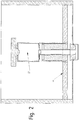
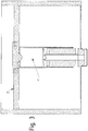
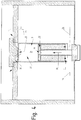
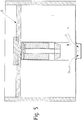
- FIGS. 1 to 5 show a first embodiment of the invention.
- FIG. 1 shows a liquid container 1, for example, a drainage channel for a sewer system, flows into the liquid through a feed, not shown.
- the liquid is indicated by the liquid level 28.
- the liquid can drain through a drain opening 2 on the underside of the liquid container 1 in a behind it, not shown sewer.
- the liquid level 28 In order to effect a flushing surge for flushing the drainage channel located behind the drainage opening, the liquid level 28 must first be raised to a higher level, the so-called triggering level 29, so that a predetermined hydrostatic pressure is built up at the bottom of the liquid tank 1. The drain opening is blocked until the trigger level 29 is reached, and then released as suddenly as possible.
- the drain opening In the moment in which the drain opening is released, is located at the drain opening of the hydrostatic Pressure on which corresponds to the trigger level 29 and thus determines as an initial condition, how strong the resulting rinse surge. The higher the trigger level 29 is selected, the stronger the resulting rinse surge.
- the amount of liquid available for the rinsing surge is influenced by the remaining two spatial dimensions of the liquid container 1.
- the drain opening 2 is selectively blocked and released by a drain valve 23, wherein the drain valve member 23 has a valve member 15 which closes the drain opening 2 with a valve body 16.
- the drain opening 2 of the liquid container 1 serves as a valve seat 26 for the valve body 16.
- the valve member 15 itself is guided within a riser pipe 3 of the drain valve 23 along the pipe extension.
- the riser pipe 3 is approximately perpendicular to the bottom 1 of the liquid container and fixed by not shown holding rods against tilting.
- the valve member 15 is in the initial state in its closed position. It is due to concerns of a low liquid level 28, as in FIG. 1 shown under the influence of gravity in the valve seat 26 formed by the drain opening 2 and thus seals the drain opening 2 from.
- the valve member 15 is made of a material having a higher density than the liquid applied in the liquid container 1, so that the valve member 15 itself can not float in the liquid.
- valve member 15 with its valve body 16 is additionally pressed into the closed position by the hydrostatic pressure applied in the liquid container 1 in the region of the discharge opening 2.
- the valve member 15 is float controlled by a float 11, wherein the glimmer 11 float in the present in the liquid container 1 liquid can.
- the float 11 is disposed on a valve stem 17 of the valve member 15, at least partially surrounding the valve stem 17.
- the float 11 has a longitudinal bore 12 into which the valve stem 17 is movably received relative to the float 11.
- Both the valve member 15 and the float 11 are approximately rotationally symmetrical components, so that the arrangement of the float 11 on the valve member 15 can be referred to as coaxial.
- the float 11 is arranged on the valve member 15 longitudinally displaceable between the shut-off 16 and a driver stop 19 for the float.
- valve member 15 and the float 11 protrude in the closed position of the valve member 15 already in the riser pipe 3, wherein the float 11 with its lateral surface 14 on the inside of the riser pipe 3 supports us thus for a guide of both the float 11 and the Coaxially arranged valve member 15 provides.
- the riser pipe 3 has a pipe section 5, which has an inlet opening 4 at the bottom.
- the inlet opening 4 can be designed as an open end face of the pipe section 5 which is executed for the outlet opening 2.
- About the inlet opening 4 is the inside of the riser pipe 3 in fluid communication with the liquid container. 1
- a vent opening 6 is provided, which is closed in the blocking position by a shut-off element 8 designed as a cover.
- the shut-off is guided by a guide 7 so that it rests in the blocking position under the influence of gravity on the top of the Rohabitess 5 and blocks the vent opening 6 with a dome-shaped sealing portion 10.
- the shut-off element 8 has a float portion 9 which is wider than the sealing portion 10. Furthermore, the shut-off element 8 is formed of a material floatable in the liquid. That is, the material of the float portion 9 has a smaller density than the liquid contained in the liquid container 1. In any case, the shut-off 8 is designed as a float or float. Therefore, variants are also conceivable in which the shut-off element 8 is made of a material having a higher density than the liquid present in the liquid container 1, but the formation of the shut-off element 8 as a floating body provides for a floating in the liquid. Conceivable are cup-shaped Embodiments or hollow configurations in which the recesses do not come into contact with the liquid level rising in the liquid container 1 during normal operation.
- the shut-off element 8 forms, in interaction with the vent opening 6, in particular with the guide 7 and the dome-shaped sealing portion 10, a venting device 24 for the riser pipe 3.
- differently designed venting devices 24 are conceivable.
- an air cushion 27 adjoins the vent opening 6, which is enclosed in the liquid container 1 within the riser pipe 3 when the liquid level 28 rises.
- liquid at the inlet opening 4 On the underside of the tube section 5 is then liquid at the inlet opening 4, which can so far enter the riser 3 until a pressure equilibrium between the internal pressure of the air cushion and adjoining the inlet opening 4 hydrostatic pressure adjusts.
- the liquid level 28 may then continue to rise until it reaches the trigger level 29, which in the FIG. 3 is drawn.
- shut-off 8 floats in the liquid and thus opens the vent opening 6, which releases the trapped and under pressure air cushion 27 from the riser abruptly.
- FIG. 4 this state is shown in which the vent opening 6 is released by the shut-off 8, so that the air cushion 27 can escape through the vent opening 6 to the outside.
- the escaping air 35 is discharged through the standing at the inlet opening 4 and under hydrostatic pressure fluid 34 displaced the room 31. Due to the pressure conditions, this displacement takes place abruptly, so that the liquid 34 can enter the riser 3 very quickly through the inlet opening 4. This ensures that the float 11 can ascend abruptly within the riser, comes to rest with a driver portion 13 to the driver stop 19 of the valve member 15 and thus the valve member 15 in the FIG. 1 shown closed position in the in FIG. 5 shown opening position entrains.
- this drain opening 2 is released abruptly by the valve member 15, so that, as in FIG. 5 shown, the liquid 34 can escape in the form of a rinsing surge through the drain opening 2 from the liquid container 1.
- the liquid level 28 then drops again in the liquid container 1 and releases the shut-off element 8, so that it falls back again due to the guide 7 into the blocking position in which the vent opening 6 of the riser pipe 3 is blocked. Due to the liquid column located in the riser 3, the float 11 remains in the open position within the riser 3 until enough liquid has drained from the liquid container 1, that the liquid level 28 the inlet opening 4 of the riser releases again, so that ambient air into the riser. 3 can enter and thus the liquid level within the riser 3 drops again. Once the liquid can drain from the riser 3 down, and the float 11 coincides with the valve member 15 in the lower closed position to close the drain opening 2 of the liquid container 1.
- a pressure compensation device 25 is provided on the drain valve, the purpose of which is to establish a pressure equalization between the vent 6 facing the top of the valve member 15 and the drain opening 2 facing bottom of the valve member 15.
- a pressure compensation channel 18 in the form of a longitudinal bore is formed in the valve member 15, which extends from the underside of the valve body 16 to the top of the Mit predominantlyanschlags 19.
- the pressure equalization channel 18 is basically closed by a check valve 33 which is formed by a seal 20 inserted in the longitudinal bore of the pressure compensation channel 18 and a disk section 21 guided on the inside of the pipe section 5.
- the seal 20 in this case has a sealing dome 22, which rests in the longitudinal bore of the pressure compensation channel and sealingly seals it.
- the passage direction 30 of the check valve 33 is directed from the drain opening 2 to the vent opening 6. This causes the trapped in the riser 3 air cushion 27 can not escape through the pressure equalization channel 18, otherwise liquid could enter through the inlet opening 4 in the riser pipe 3, before the shut-off 8, the vent opening 6 releases.
- a bridging portion 32 is mounted, which is opposite to the upper end of the float 11 and which can receive the Mit supportiveanschlag 19 of the valve member 15. To this end, the bridging portion 32 connects to a centrally disposed in the float 11 longitudinal bore 12, which receives the valve stem 17 of the valve member 15.
- the bridging portion 32 is formed so far recessed that when receiving the Mit demandinganschlags 19 in the bridging portion 32, the upper end of the float 11 can engage the disc portion 21 of the seal 20, which protrudes radially relative to the Mit demandinganschlag 19. It should be noted that neither the driver stop 19 nor the disc portion 21 sealingly abut the inside of the pipe section 5, so that both the valve member 15 and the float 11 can move freely to the vent opening 6 out.
- the check valve 33 may also open automatically before the bridging portion 32 can engage the disc portion 21. This is the case when a pressure gradient in the forward direction 30 abuts against the check valve 33, so that it is temporarily raised from its closed position to an open position under the action of the pressure gradient and falls back into the closed position after pressure equalization.
- FIGS. 6 and 7 show a second embodiment of the invention, which differs from the first embodiment essentially in that the float 11 and the valve member 15 are formed as a one-piece valve member 37.
- the valve member 37 protrudes in the in FIG. 6 illustrated closed position in the riser pipe 3 and simultaneously closes with its valve body 16, the drain opening 2 of the liquid container. 1
- liquid 34 enter through provided on the riser 3 overflow openings 42 in a top portion 47 of the riser pipe 3, so that a float 38 therein can float.
- the float 38 is formed in the present case as a floating body in the form of a cup open in the direction of the vent opening 6, in which an air cushion 27 is enclosed in the upper section 47 when liquid 34 enters.
- the float 38 is connected by means of the guide 7 with the shut-off 8, so that the floating float 38 simultaneously lifts the shut-8 and thus actuates the venting device 24 and the vent opening 6 releases.
- a locking bar 41 is additionally provided on the guide 7, which is arranged within the space 31 of the riser pipe 3 and prevents by positive locking that the guide 7 is disengaged from the riser pipe 3 ,
- the trained as a float 11 valve member 37 which is presently designed as a hollow body, has a float interior 44 which is at least partially filled with ballast 43, whereby the density of the float 11 is specifically adapted.
- the density is so great that a sufficient sealing effect between valve body 16 and valve seat 26 in the closed position due to the weight of the valve member 37 is present.
- the density of the valve member 37 is small enough that the valve member 37 is reliably transferred to the open position upon increase of the inner level 40.
- the trained as a float 11 valve member 37 may also be made of a buoyant solid material.
- the drain valve 36 with the riser pipe 3 can be inserted according to the second embodiment as a retrofit part in an existing liquid container 1.
- the drain valve 36 can be used in a vertical mounting in the liquid container 1 and with feet 45, for example, three over the circumference of the riser 3 evenly distributed feet 45, supported on the liquid container 1.
- the riser pipe 3 is supported with its feet 45 at a present in the liquid container 1 paragraph 48, which could be part of the valve seat 26 of a previously installed drain valve, for example.
- centering bevels 46 may be provided on one or more of the feet. These centering slopes 46 cooperate with the shoulder 48 of the liquid container 1 in such a way that the riser pipe 3 automatically into the required installation position slides.
- the riser pipe 3 can then be secured by means of additional fastening means against slipping out of the installation position.
Landscapes
- Health & Medical Sciences (AREA)
- Life Sciences & Earth Sciences (AREA)
- Engineering & Computer Science (AREA)
- Hydrology & Water Resources (AREA)
- Public Health (AREA)
- Water Supply & Treatment (AREA)
- Float Valves (AREA)
Priority Applications (1)
| Application Number | Priority Date | Filing Date | Title |
|---|---|---|---|
| PL17156476T PL3219864T3 (pl) | 2016-03-17 | 2017-02-16 | Zbiornik na ciecz z zaworem opróżniającym oraz odpowiedni sposób generowania fali spiętrzenia przepłukującego |
Applications Claiming Priority (1)
| Application Number | Priority Date | Filing Date | Title |
|---|---|---|---|
| DE102016104936.0A DE102016104936A1 (de) | 2016-03-17 | 2016-03-17 | Entleerungsventil für einen Flüssigkeitsbehälter, Flüssigkeitsbehälter zum Erzeugen eines Spülschwalls und Verfahren zum Erzeugen eines Spülschwalls |
Publications (2)
| Publication Number | Publication Date |
|---|---|
| EP3219864A1 true EP3219864A1 (fr) | 2017-09-20 |
| EP3219864B1 EP3219864B1 (fr) | 2020-02-26 |
Family
ID=58098475
Family Applications (1)
| Application Number | Title | Priority Date | Filing Date |
|---|---|---|---|
| EP17156476.8A Active EP3219864B1 (fr) | 2016-03-17 | 2017-02-16 | Récipient de liquide comprenant une soupape die vidange et utilisation correspondante pour produire une vague de rinçage |
Country Status (3)
| Country | Link |
|---|---|
| EP (1) | EP3219864B1 (fr) |
| DE (1) | DE102016104936A1 (fr) |
| PL (1) | PL3219864T3 (fr) |
Families Citing this family (1)
| Publication number | Priority date | Publication date | Assignee | Title |
|---|---|---|---|---|
| CN118148158B (zh) * | 2024-05-10 | 2024-07-09 | 中国化学工程第九建设有限公司 | 一种基坑开挖边坡防护结构 |
Citations (8)
| Publication number | Priority date | Publication date | Assignee | Title |
|---|---|---|---|---|
| US3987501A (en) * | 1974-06-17 | 1976-10-26 | Producers Specialty & Mfg. Co., Inc. | Toilet flush assembly |
| DE3915076A1 (de) * | 1989-05-09 | 1990-11-15 | Alloy Tech Ag | Vorrichtung an einem fluessigkeitsspeicherraum zum selbsttaetigen spuelen des leergelaufenen speicherraumes |
| DE29604004U1 (de) * | 1996-03-05 | 1997-07-10 | BIONIK GmbH - Innovative Technik für die Umwelt, 65232 Taunusstein | Vorrichtung zum stoßweisen Entleeren eines Flüssigkeitsstauraumes, insbesondere in einem Kanalisationsnetz |
| DE19930346A1 (de) | 1999-07-02 | 2001-01-18 | Klaus Ulrich Giehl | Kanalspüler |
| DE10010836A1 (de) | 2000-03-09 | 2001-09-27 | Lothar Liebau | Verfahren zur Schwallspülung eines Mischwasserkanals sowie Vorrichtung hierzu |
| DE20207805U1 (de) | 2002-04-27 | 2002-09-05 | Preiss, Peter, 95448 Bayreuth | Einrichtung zur Spülung von Anschlusskanälen, Grund- und Sammelleitungen |
| EP1669500A1 (fr) | 2004-12-08 | 2006-06-14 | Steinhardt GmbH | Dispositif pour la chasse des égouts comprenant un joint |
| DE202012006401U1 (de) | 2012-07-04 | 2012-10-08 | Biogest Ag | Kanalspüler zur Reinigung eines Ablaufkanals für Regen- oder Mischwasser in einem Spülschacht |
Family Cites Families (1)
| Publication number | Priority date | Publication date | Assignee | Title |
|---|---|---|---|---|
| SE338953B (fr) * | 1970-11-26 | 1971-09-20 | Electrolux Ab |
-
2016
- 2016-03-17 DE DE102016104936.0A patent/DE102016104936A1/de not_active Withdrawn
-
2017
- 2017-02-16 PL PL17156476T patent/PL3219864T3/pl unknown
- 2017-02-16 EP EP17156476.8A patent/EP3219864B1/fr active Active
Patent Citations (8)
| Publication number | Priority date | Publication date | Assignee | Title |
|---|---|---|---|---|
| US3987501A (en) * | 1974-06-17 | 1976-10-26 | Producers Specialty & Mfg. Co., Inc. | Toilet flush assembly |
| DE3915076A1 (de) * | 1989-05-09 | 1990-11-15 | Alloy Tech Ag | Vorrichtung an einem fluessigkeitsspeicherraum zum selbsttaetigen spuelen des leergelaufenen speicherraumes |
| DE29604004U1 (de) * | 1996-03-05 | 1997-07-10 | BIONIK GmbH - Innovative Technik für die Umwelt, 65232 Taunusstein | Vorrichtung zum stoßweisen Entleeren eines Flüssigkeitsstauraumes, insbesondere in einem Kanalisationsnetz |
| DE19930346A1 (de) | 1999-07-02 | 2001-01-18 | Klaus Ulrich Giehl | Kanalspüler |
| DE10010836A1 (de) | 2000-03-09 | 2001-09-27 | Lothar Liebau | Verfahren zur Schwallspülung eines Mischwasserkanals sowie Vorrichtung hierzu |
| DE20207805U1 (de) | 2002-04-27 | 2002-09-05 | Preiss, Peter, 95448 Bayreuth | Einrichtung zur Spülung von Anschlusskanälen, Grund- und Sammelleitungen |
| EP1669500A1 (fr) | 2004-12-08 | 2006-06-14 | Steinhardt GmbH | Dispositif pour la chasse des égouts comprenant un joint |
| DE202012006401U1 (de) | 2012-07-04 | 2012-10-08 | Biogest Ag | Kanalspüler zur Reinigung eines Ablaufkanals für Regen- oder Mischwasser in einem Spülschacht |
Also Published As
| Publication number | Publication date |
|---|---|
| PL3219864T3 (pl) | 2020-09-07 |
| EP3219864B1 (fr) | 2020-02-26 |
| DE102016104936A1 (de) | 2017-09-21 |
Similar Documents
| Publication | Publication Date | Title |
|---|---|---|
| DE69311091T2 (de) | Luftkontrollsystem für hydropneumatischen Behälter | |
| CH663045A5 (de) | Ablaufgarnitur fuer einen spuelkasten. | |
| EP2910685B1 (fr) | Ascenseur à poissons et procédé de nettoyage d'un ascenseur à poissons | |
| DE3915076C2 (fr) | ||
| EP3219864B1 (fr) | Récipient de liquide comprenant une soupape die vidange et utilisation correspondante pour produire une vague de rinçage | |
| EP0083358A1 (fr) | Installation de remplissage automatique de cellules de batterie. | |
| DE9016513U1 (de) | Vorrichtung zum Spülen eines Kanales | |
| DE69109536T2 (de) | Schwimmventil mit Niveauregelung durch Gestell, insbesondere für Wasserbehälter von Sanitäranlagen. | |
| EP1475484B1 (fr) | Dispositif pour la chasse des égouts | |
| DE19901993C1 (de) | Spülvorrichtung für Flüssigkeitsspeicherräume | |
| DE2337853C2 (de) | Rückstau- und Geruchsverschluß für Flüssigkelten, Insbesondere Abwässer | |
| DE4137768C1 (en) | Automatic hoist with downwards open bell - has outlet tube, whose top end retains movably top-open float pot | |
| DE102010001906B4 (de) | Selbsttätig arbeitende Verschlussvorrichtung und Leichtflüssigkeitsabscheider mit einer selbsttätig arbeitenden Verschlussvorrichtung | |
| DE4425244C1 (de) | Ventil zur Ent- und Belüftung insbesondere einer Abwasserleitung | |
| DE60302619T2 (de) | Automatische Absperrvorrichtung eines Durchflusskanals | |
| EP0619131B1 (fr) | Séparateur de liquide léger avec fermeture automatique | |
| EP4095324B1 (fr) | Système de rinçage | |
| DE102010005778A1 (de) | Vorrichtung zum selbsttätigen Verschließen eines Zulaufes eines Behälters zur Aufnahme einer Flüssigkeit und Abscheidevorrichtung | |
| EP0565483A1 (fr) | Bassin dans une installation d'eaux usées | |
| DE69803559T2 (de) | Einrichtung zum regeln einer flüssigkeitsströmung | |
| EP0892117A1 (fr) | Dispositif d'écoulement d'un réservoir de chasse d'eau | |
| DE10330332A1 (de) | Spülbehälter für ein WC, mit einem als Faltenbalg ausgebildeten Ablauf | |
| DE29604004U1 (de) | Vorrichtung zum stoßweisen Entleeren eines Flüssigkeitsstauraumes, insbesondere in einem Kanalisationsnetz | |
| DE525373C (de) | Durchflusssperre fuer Leichtfluessigkeitsabscheider | |
| DE60020356T2 (de) | Schwimmerventil mit zwei Trichtern |
Legal Events
| Date | Code | Title | Description |
|---|---|---|---|
| PUAI | Public reference made under article 153(3) epc to a published international application that has entered the european phase |
Free format text: ORIGINAL CODE: 0009012 |
|
| STAA | Information on the status of an ep patent application or granted ep patent |
Free format text: STATUS: THE APPLICATION HAS BEEN PUBLISHED |
|
| AK | Designated contracting states |
Kind code of ref document: A1 Designated state(s): AL AT BE BG CH CY CZ DE DK EE ES FI FR GB GR HR HU IE IS IT LI LT LU LV MC MK MT NL NO PL PT RO RS SE SI SK SM TR |
|
| AX | Request for extension of the european patent |
Extension state: BA ME |
|
| STAA | Information on the status of an ep patent application or granted ep patent |
Free format text: STATUS: REQUEST FOR EXAMINATION WAS MADE |
|
| 17P | Request for examination filed |
Effective date: 20171110 |
|
| RBV | Designated contracting states (corrected) |
Designated state(s): AL AT BE BG CH CY CZ DE DK EE ES FI FR GB GR HR HU IE IS IT LI LT LU LV MC MK MT NL NO PL PT RO RS SE SI SK SM TR |
|
| STAA | Information on the status of an ep patent application or granted ep patent |
Free format text: STATUS: EXAMINATION IS IN PROGRESS |
|
| 17Q | First examination report despatched |
Effective date: 20180522 |
|
| GRAP | Despatch of communication of intention to grant a patent |
Free format text: ORIGINAL CODE: EPIDOSNIGR1 |
|
| STAA | Information on the status of an ep patent application or granted ep patent |
Free format text: STATUS: GRANT OF PATENT IS INTENDED |
|
| INTG | Intention to grant announced |
Effective date: 20191018 |
|
| GRAS | Grant fee paid |
Free format text: ORIGINAL CODE: EPIDOSNIGR3 |
|
| GRAA | (expected) grant |
Free format text: ORIGINAL CODE: 0009210 |
|
| STAA | Information on the status of an ep patent application or granted ep patent |
Free format text: STATUS: THE PATENT HAS BEEN GRANTED |
|
| AK | Designated contracting states |
Kind code of ref document: B1 Designated state(s): AL AT BE BG CH CY CZ DE DK EE ES FI FR GB GR HR HU IE IS IT LI LT LU LV MC MK MT NL NO PL PT RO RS SE SI SK SM TR |
|
| REG | Reference to a national code |
Ref country code: GB Ref legal event code: FG4D Free format text: NOT ENGLISH |
|
| REG | Reference to a national code |
Ref country code: CH Ref legal event code: EP |
|
| REG | Reference to a national code |
Ref country code: AT Ref legal event code: REF Ref document number: 1237774 Country of ref document: AT Kind code of ref document: T Effective date: 20200315 |
|
| REG | Reference to a national code |
Ref country code: IE Ref legal event code: FG4D Free format text: LANGUAGE OF EP DOCUMENT: GERMAN |
|
| REG | Reference to a national code |
Ref country code: DE Ref legal event code: R096 Ref document number: 502017003925 Country of ref document: DE |
|
| REG | Reference to a national code |
Ref country code: NL Ref legal event code: FP |
|
| PG25 | Lapsed in a contracting state [announced via postgrant information from national office to epo] |
Ref country code: FI Free format text: LAPSE BECAUSE OF FAILURE TO SUBMIT A TRANSLATION OF THE DESCRIPTION OR TO PAY THE FEE WITHIN THE PRESCRIBED TIME-LIMIT Effective date: 20200226 Ref country code: RS Free format text: LAPSE BECAUSE OF FAILURE TO SUBMIT A TRANSLATION OF THE DESCRIPTION OR TO PAY THE FEE WITHIN THE PRESCRIBED TIME-LIMIT Effective date: 20200226 Ref country code: NO Free format text: LAPSE BECAUSE OF FAILURE TO SUBMIT A TRANSLATION OF THE DESCRIPTION OR TO PAY THE FEE WITHIN THE PRESCRIBED TIME-LIMIT Effective date: 20200526 |
|
| REG | Reference to a national code |
Ref country code: LT Ref legal event code: MG4D |
|
| PG25 | Lapsed in a contracting state [announced via postgrant information from national office to epo] |
Ref country code: BG Free format text: LAPSE BECAUSE OF FAILURE TO SUBMIT A TRANSLATION OF THE DESCRIPTION OR TO PAY THE FEE WITHIN THE PRESCRIBED TIME-LIMIT Effective date: 20200526 Ref country code: IS Free format text: LAPSE BECAUSE OF FAILURE TO SUBMIT A TRANSLATION OF THE DESCRIPTION OR TO PAY THE FEE WITHIN THE PRESCRIBED TIME-LIMIT Effective date: 20200626 Ref country code: LV Free format text: LAPSE BECAUSE OF FAILURE TO SUBMIT A TRANSLATION OF THE DESCRIPTION OR TO PAY THE FEE WITHIN THE PRESCRIBED TIME-LIMIT Effective date: 20200226 Ref country code: SE Free format text: LAPSE BECAUSE OF FAILURE TO SUBMIT A TRANSLATION OF THE DESCRIPTION OR TO PAY THE FEE WITHIN THE PRESCRIBED TIME-LIMIT Effective date: 20200226 Ref country code: HR Free format text: LAPSE BECAUSE OF FAILURE TO SUBMIT A TRANSLATION OF THE DESCRIPTION OR TO PAY THE FEE WITHIN THE PRESCRIBED TIME-LIMIT Effective date: 20200226 Ref country code: GR Free format text: LAPSE BECAUSE OF FAILURE TO SUBMIT A TRANSLATION OF THE DESCRIPTION OR TO PAY THE FEE WITHIN THE PRESCRIBED TIME-LIMIT Effective date: 20200527 |
|
| PG25 | Lapsed in a contracting state [announced via postgrant information from national office to epo] |
Ref country code: SK Free format text: LAPSE BECAUSE OF FAILURE TO SUBMIT A TRANSLATION OF THE DESCRIPTION OR TO PAY THE FEE WITHIN THE PRESCRIBED TIME-LIMIT Effective date: 20200226 Ref country code: PT Free format text: LAPSE BECAUSE OF FAILURE TO SUBMIT A TRANSLATION OF THE DESCRIPTION OR TO PAY THE FEE WITHIN THE PRESCRIBED TIME-LIMIT Effective date: 20200719 Ref country code: DK Free format text: LAPSE BECAUSE OF FAILURE TO SUBMIT A TRANSLATION OF THE DESCRIPTION OR TO PAY THE FEE WITHIN THE PRESCRIBED TIME-LIMIT Effective date: 20200226 Ref country code: SM Free format text: LAPSE BECAUSE OF FAILURE TO SUBMIT A TRANSLATION OF THE DESCRIPTION OR TO PAY THE FEE WITHIN THE PRESCRIBED TIME-LIMIT Effective date: 20200226 Ref country code: EE Free format text: LAPSE BECAUSE OF FAILURE TO SUBMIT A TRANSLATION OF THE DESCRIPTION OR TO PAY THE FEE WITHIN THE PRESCRIBED TIME-LIMIT Effective date: 20200226 Ref country code: LT Free format text: LAPSE BECAUSE OF FAILURE TO SUBMIT A TRANSLATION OF THE DESCRIPTION OR TO PAY THE FEE WITHIN THE PRESCRIBED TIME-LIMIT Effective date: 20200226 Ref country code: RO Free format text: LAPSE BECAUSE OF FAILURE TO SUBMIT A TRANSLATION OF THE DESCRIPTION OR TO PAY THE FEE WITHIN THE PRESCRIBED TIME-LIMIT Effective date: 20200226 Ref country code: ES Free format text: LAPSE BECAUSE OF FAILURE TO SUBMIT A TRANSLATION OF THE DESCRIPTION OR TO PAY THE FEE WITHIN THE PRESCRIBED TIME-LIMIT Effective date: 20200226 Ref country code: CZ Free format text: LAPSE BECAUSE OF FAILURE TO SUBMIT A TRANSLATION OF THE DESCRIPTION OR TO PAY THE FEE WITHIN THE PRESCRIBED TIME-LIMIT Effective date: 20200226 |
|
| REG | Reference to a national code |
Ref country code: DE Ref legal event code: R097 Ref document number: 502017003925 Country of ref document: DE |
|
| PLBE | No opposition filed within time limit |
Free format text: ORIGINAL CODE: 0009261 |
|
| STAA | Information on the status of an ep patent application or granted ep patent |
Free format text: STATUS: NO OPPOSITION FILED WITHIN TIME LIMIT |
|
| PG25 | Lapsed in a contracting state [announced via postgrant information from national office to epo] |
Ref country code: IT Free format text: LAPSE BECAUSE OF FAILURE TO SUBMIT A TRANSLATION OF THE DESCRIPTION OR TO PAY THE FEE WITHIN THE PRESCRIBED TIME-LIMIT Effective date: 20200226 |
|
| 26N | No opposition filed |
Effective date: 20201127 |
|
| PG25 | Lapsed in a contracting state [announced via postgrant information from national office to epo] |
Ref country code: SI Free format text: LAPSE BECAUSE OF FAILURE TO SUBMIT A TRANSLATION OF THE DESCRIPTION OR TO PAY THE FEE WITHIN THE PRESCRIBED TIME-LIMIT Effective date: 20200226 |
|
| PG25 | Lapsed in a contracting state [announced via postgrant information from national office to epo] |
Ref country code: MC Free format text: LAPSE BECAUSE OF FAILURE TO SUBMIT A TRANSLATION OF THE DESCRIPTION OR TO PAY THE FEE WITHIN THE PRESCRIBED TIME-LIMIT Effective date: 20200226 |
|
| GBPC | Gb: european patent ceased through non-payment of renewal fee |
Effective date: 20210216 |
|
| PG25 | Lapsed in a contracting state [announced via postgrant information from national office to epo] |
Ref country code: CH Free format text: LAPSE BECAUSE OF NON-PAYMENT OF DUE FEES Effective date: 20210228 Ref country code: LI Free format text: LAPSE BECAUSE OF NON-PAYMENT OF DUE FEES Effective date: 20210228 Ref country code: LU Free format text: LAPSE BECAUSE OF NON-PAYMENT OF DUE FEES Effective date: 20210216 |
|
| PG25 | Lapsed in a contracting state [announced via postgrant information from national office to epo] |
Ref country code: GB Free format text: LAPSE BECAUSE OF NON-PAYMENT OF DUE FEES Effective date: 20210216 Ref country code: IE Free format text: LAPSE BECAUSE OF NON-PAYMENT OF DUE FEES Effective date: 20210216 |
|
| REG | Reference to a national code |
Ref country code: DE Ref legal event code: R081 Ref document number: 502017003925 Country of ref document: DE Owner name: P.V. BETONFERTIGTEILWERKE GMBH, DE Free format text: FORMER OWNER: GEBR. FASEL BETONWERK GMBH, 56472 NISTERAU, DE |
|
| PGFP | Annual fee paid to national office [announced via postgrant information from national office to epo] |
Ref country code: NL Payment date: 20220216 Year of fee payment: 6 Ref country code: FR Payment date: 20220216 Year of fee payment: 6 Ref country code: BE Payment date: 20220216 Year of fee payment: 6 |
|
| PG25 | Lapsed in a contracting state [announced via postgrant information from national office to epo] |
Ref country code: HU Free format text: LAPSE BECAUSE OF FAILURE TO SUBMIT A TRANSLATION OF THE DESCRIPTION OR TO PAY THE FEE WITHIN THE PRESCRIBED TIME-LIMIT; INVALID AB INITIO Effective date: 20170216 |
|
| PG25 | Lapsed in a contracting state [announced via postgrant information from national office to epo] |
Ref country code: CY Free format text: LAPSE BECAUSE OF FAILURE TO SUBMIT A TRANSLATION OF THE DESCRIPTION OR TO PAY THE FEE WITHIN THE PRESCRIBED TIME-LIMIT Effective date: 20200226 |
|
| P01 | Opt-out of the competence of the unified patent court (upc) registered |
Effective date: 20230530 |
|
| REG | Reference to a national code |
Ref country code: NL Ref legal event code: MM Effective date: 20230301 |
|
| REG | Reference to a national code |
Ref country code: BE Ref legal event code: MM Effective date: 20230228 |
|
| PG25 | Lapsed in a contracting state [announced via postgrant information from national office to epo] |
Ref country code: NL Free format text: LAPSE BECAUSE OF NON-PAYMENT OF DUE FEES Effective date: 20230301 |
|
| PG25 | Lapsed in a contracting state [announced via postgrant information from national office to epo] |
Ref country code: FR Free format text: LAPSE BECAUSE OF NON-PAYMENT OF DUE FEES Effective date: 20230228 |
|
| PG25 | Lapsed in a contracting state [announced via postgrant information from national office to epo] |
Ref country code: BE Free format text: LAPSE BECAUSE OF NON-PAYMENT OF DUE FEES Effective date: 20230228 |
|
| REG | Reference to a national code |
Ref country code: AT Ref legal event code: PC Ref document number: 1237774 Country of ref document: AT Kind code of ref document: T Owner name: P.V. BETONFERTIGTEILWERKE GMBH, DE Effective date: 20240212 |
|
| PG25 | Lapsed in a contracting state [announced via postgrant information from national office to epo] |
Ref country code: MK Free format text: LAPSE BECAUSE OF FAILURE TO SUBMIT A TRANSLATION OF THE DESCRIPTION OR TO PAY THE FEE WITHIN THE PRESCRIBED TIME-LIMIT Effective date: 20200226 |
|
| PG25 | Lapsed in a contracting state [announced via postgrant information from national office to epo] |
Ref country code: TR Free format text: LAPSE BECAUSE OF FAILURE TO SUBMIT A TRANSLATION OF THE DESCRIPTION OR TO PAY THE FEE WITHIN THE PRESCRIBED TIME-LIMIT Effective date: 20200226 |
|
| PG25 | Lapsed in a contracting state [announced via postgrant information from national office to epo] |
Ref country code: MT Free format text: LAPSE BECAUSE OF FAILURE TO SUBMIT A TRANSLATION OF THE DESCRIPTION OR TO PAY THE FEE WITHIN THE PRESCRIBED TIME-LIMIT Effective date: 20200226 |
|
| PGFP | Annual fee paid to national office [announced via postgrant information from national office to epo] |
Ref country code: DE Payment date: 20260228 Year of fee payment: 10 |
|
| PGFP | Annual fee paid to national office [announced via postgrant information from national office to epo] |
Ref country code: AT Payment date: 20260219 Year of fee payment: 10 |
|
| PGFP | Annual fee paid to national office [announced via postgrant information from national office to epo] |
Ref country code: PL Payment date: 20260209 Year of fee payment: 10 |