EP3219948B1 - Hydraulikkreislaufsystem und elektronische karte mit sicherungsmittel der karte im falle eines lecks im kreislauf - Google Patents
Hydraulikkreislaufsystem und elektronische karte mit sicherungsmittel der karte im falle eines lecks im kreislauf Download PDFInfo
- Publication number
- EP3219948B1 EP3219948B1 EP17157857.8A EP17157857A EP3219948B1 EP 3219948 B1 EP3219948 B1 EP 3219948B1 EP 17157857 A EP17157857 A EP 17157857A EP 3219948 B1 EP3219948 B1 EP 3219948B1
- Authority
- EP
- European Patent Office
- Prior art keywords
- card
- electronic card
- electronic
- temperature threshold
- control unit
- Prior art date
- Legal status (The legal status is an assumption and is not a legal conclusion. Google has not performed a legal analysis and makes no representation as to the accuracy of the status listed.)
- Active
Links
Images
Classifications
-
- F—MECHANICAL ENGINEERING; LIGHTING; HEATING; WEAPONS; BLASTING
- F01—MACHINES OR ENGINES IN GENERAL; ENGINE PLANTS IN GENERAL; STEAM ENGINES
- F01N—GAS-FLOW SILENCERS OR EXHAUST APPARATUS FOR MACHINES OR ENGINES IN GENERAL; GAS-FLOW SILENCERS OR EXHAUST APPARATUS FOR INTERNAL-COMBUSTION ENGINES
- F01N3/00—Exhaust or silencing apparatus having means for purifying, rendering innocuous, or otherwise treating exhaust
- F01N3/08—Exhaust or silencing apparatus having means for purifying, rendering innocuous, or otherwise treating exhaust for rendering innocuous
- F01N3/10—Exhaust or silencing apparatus having means for purifying, rendering innocuous, or otherwise treating exhaust for rendering innocuous by thermal or catalytic conversion of noxious components of exhaust
- F01N3/18—Exhaust or silencing apparatus having means for purifying, rendering innocuous, or otherwise treating exhaust for rendering innocuous by thermal or catalytic conversion of noxious components of exhaust characterised by methods of operation; Control
- F01N3/20—Exhaust or silencing apparatus having means for purifying, rendering innocuous, or otherwise treating exhaust for rendering innocuous by thermal or catalytic conversion of noxious components of exhaust characterised by methods of operation; Control specially adapted for catalytic conversion
- F01N3/206—Adding periodically or continuously substances to exhaust gases for promoting purification, e.g. catalytic material in liquid form, NOx reducing agents
- F01N3/208—Control of selective catalytic reduction [SCR], e.g. by adjusting the dosing of reducing agent
-
- F—MECHANICAL ENGINEERING; LIGHTING; HEATING; WEAPONS; BLASTING
- F01—MACHINES OR ENGINES IN GENERAL; ENGINE PLANTS IN GENERAL; STEAM ENGINES
- F01N—GAS-FLOW SILENCERS OR EXHAUST APPARATUS FOR MACHINES OR ENGINES IN GENERAL; GAS-FLOW SILENCERS OR EXHAUST APPARATUS FOR INTERNAL-COMBUSTION ENGINES
- F01N11/00—Monitoring or diagnostic devices for exhaust-gas treatment apparatus
- F01N11/002—Monitoring or diagnostic devices for exhaust-gas treatment apparatus the diagnostic devices measuring or estimating temperature or pressure in, or downstream of the exhaust apparatus
-
- F—MECHANICAL ENGINEERING; LIGHTING; HEATING; WEAPONS; BLASTING
- F01—MACHINES OR ENGINES IN GENERAL; ENGINE PLANTS IN GENERAL; STEAM ENGINES
- F01N—GAS-FLOW SILENCERS OR EXHAUST APPARATUS FOR MACHINES OR ENGINES IN GENERAL; GAS-FLOW SILENCERS OR EXHAUST APPARATUS FOR INTERNAL-COMBUSTION ENGINES
- F01N2550/00—Monitoring or diagnosing the deterioration of exhaust systems
- F01N2550/05—Systems for adding substances into exhaust
-
- F—MECHANICAL ENGINEERING; LIGHTING; HEATING; WEAPONS; BLASTING
- F01—MACHINES OR ENGINES IN GENERAL; ENGINE PLANTS IN GENERAL; STEAM ENGINES
- F01N—GAS-FLOW SILENCERS OR EXHAUST APPARATUS FOR MACHINES OR ENGINES IN GENERAL; GAS-FLOW SILENCERS OR EXHAUST APPARATUS FOR INTERNAL-COMBUSTION ENGINES
- F01N2560/00—Exhaust systems with means for detecting or measuring exhaust gas components or characteristics
- F01N2560/06—Exhaust systems with means for detecting or measuring exhaust gas components or characteristics the means being a temperature sensor
-
- F—MECHANICAL ENGINEERING; LIGHTING; HEATING; WEAPONS; BLASTING
- F01—MACHINES OR ENGINES IN GENERAL; ENGINE PLANTS IN GENERAL; STEAM ENGINES
- F01N—GAS-FLOW SILENCERS OR EXHAUST APPARATUS FOR MACHINES OR ENGINES IN GENERAL; GAS-FLOW SILENCERS OR EXHAUST APPARATUS FOR INTERNAL-COMBUSTION ENGINES
- F01N2610/00—Adding substances to exhaust gases
- F01N2610/14—Arrangements for the supply of substances, e.g. conduits
- F01N2610/1433—Pumps
-
- F—MECHANICAL ENGINEERING; LIGHTING; HEATING; WEAPONS; BLASTING
- F01—MACHINES OR ENGINES IN GENERAL; ENGINE PLANTS IN GENERAL; STEAM ENGINES
- F01N—GAS-FLOW SILENCERS OR EXHAUST APPARATUS FOR MACHINES OR ENGINES IN GENERAL; GAS-FLOW SILENCERS OR EXHAUST APPARATUS FOR INTERNAL-COMBUSTION ENGINES
- F01N2900/00—Details of electrical control or of the monitoring of the exhaust gas treating apparatus
- F01N2900/06—Parameters used for exhaust control or diagnosing
- F01N2900/16—Parameters used for exhaust control or diagnosing said parameters being related to the exhaust apparatus, e.g. particulate filter or catalyst
- F01N2900/1602—Temperature of exhaust gas apparatus
-
- Y—GENERAL TAGGING OF NEW TECHNOLOGICAL DEVELOPMENTS; GENERAL TAGGING OF CROSS-SECTIONAL TECHNOLOGIES SPANNING OVER SEVERAL SECTIONS OF THE IPC; TECHNICAL SUBJECTS COVERED BY FORMER USPC CROSS-REFERENCE ART COLLECTIONS [XRACs] AND DIGESTS
- Y02—TECHNOLOGIES OR APPLICATIONS FOR MITIGATION OR ADAPTATION AGAINST CLIMATE CHANGE
- Y02A—TECHNOLOGIES FOR ADAPTATION TO CLIMATE CHANGE
- Y02A50/00—TECHNOLOGIES FOR ADAPTATION TO CLIMATE CHANGE in human health protection, e.g. against extreme weather
- Y02A50/20—Air quality improvement or preservation, e.g. vehicle emission control or emission reduction by using catalytic converters
-
- Y—GENERAL TAGGING OF NEW TECHNOLOGICAL DEVELOPMENTS; GENERAL TAGGING OF CROSS-SECTIONAL TECHNOLOGIES SPANNING OVER SEVERAL SECTIONS OF THE IPC; TECHNICAL SUBJECTS COVERED BY FORMER USPC CROSS-REFERENCE ART COLLECTIONS [XRACs] AND DIGESTS
- Y02—TECHNOLOGIES OR APPLICATIONS FOR MITIGATION OR ADAPTATION AGAINST CLIMATE CHANGE
- Y02T—CLIMATE CHANGE MITIGATION TECHNOLOGIES RELATED TO TRANSPORTATION
- Y02T10/00—Road transport of goods or passengers
- Y02T10/10—Internal combustion engine [ICE] based vehicles
- Y02T10/12—Improving ICE efficiencies
-
- Y—GENERAL TAGGING OF NEW TECHNOLOGICAL DEVELOPMENTS; GENERAL TAGGING OF CROSS-SECTIONAL TECHNOLOGIES SPANNING OVER SEVERAL SECTIONS OF THE IPC; TECHNICAL SUBJECTS COVERED BY FORMER USPC CROSS-REFERENCE ART COLLECTIONS [XRACs] AND DIGESTS
- Y02—TECHNOLOGIES OR APPLICATIONS FOR MITIGATION OR ADAPTATION AGAINST CLIMATE CHANGE
- Y02T—CLIMATE CHANGE MITIGATION TECHNOLOGIES RELATED TO TRANSPORTATION
- Y02T10/00—Road transport of goods or passengers
- Y02T10/10—Internal combustion engine [ICE] based vehicles
- Y02T10/40—Engine management systems
Definitions
- the present invention relates to pollution control systems of nitrogen oxides.
- the invention relates more particularly to a system with a hydraulic circuit and an electronic card with means for securing the card in the event of leakage of the circuit.
- the invention also relates to a device for treating nitrogen oxides by selective catalytic reaction comprising such a system.
- reducing agent urea in aqueous solution and to store this aqueous solution in a tank.
- a reducing agent supply circuit is known for example from the document EP2527609A1 or the document FR2983237A1 .
- This box comprises elements of the reducing agent supply circuit such as a pump, a solenoid valve and electrical components such as connectors, a heating element of the reducing agent and electronic components such as a card electronic.
- reducing agent leaks can cause damage by heating or chemical reaction on electrical and / or electronic components.
- the object of the present invention is therefore to limit or eradicate the risk of such damage to the electrical components and / or in case of leakage of reducing agent in this electronic box.
- the technical effect is to obtain a leak detector by an indirect route using the already existing means on the map, here a temperature measurement of the map.
- the electronic card has a power supply relay of the hydraulic unit, this relay being connected to the electronic control unit, and the electronic control unit being designed to cut off this relay if the threshold excessive temperature is exceeded.
- the conductive liquid is urea in aqueous solution.
- the invention also relates to a device for treating nitrogen oxides by selective catalytic reaction comprising a system of the invention.
- the invention also relates to an engine assembly comprising an internal combustion engine and a computer which supervises the operation of the internal combustion engine, further comprising such a device for treating nitrogen oxides by selective catalytic reaction.
- the electronic control unit is designed to communicate to the computer that the excessive temperature threshold is exceeded.
- the motor assembly comprises a supply line of the electronic card equipped with a general power supply relay of the nitrogen oxide treatment device by selective catalytic reaction, and in that the calculator is designed to cut off this relay when it receives from the electronic control unit the fact that the excessive temperature threshold is exceeded.
- the excess temperature threshold is chosen to be greater than a predetermined maximum temperature threshold that the electronic card can reach without the presence of liquid leakage on the card and with the internal combustion engine operating so as to cause the heating to occur. maximum of the electronic card.
- the excess temperature threshold is chosen to be greater than 100 ° C.
- the invention also relates to a vehicle comprising an assembly of the invention.
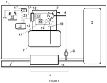
- the figure 1 presents a motor vehicle 1 is an internal combustion engine 2 to provide for its movement.
- the internal combustion engine 2 is preferably a diesel engine.
- the internal combustion engine 2 evacuates the exhaust gases produced during its operation by an exhaust line 3.
- the exhaust line 3 comprises a device 4 for treating the nitrogen oxides, NOx, by selective catalytic reaction between NOx and a reducing agent, which will still be designated by SCR device.
- reducing agent is meant an agent that can react chemically with nitrogen oxides, NOx, to transform them into products deemed less polluting.
- the device 4 SCR comprises a reducing agent supply circuit.
- This hydraulic circuit for reducing agent feed starts with a reservoir 7 of reducing agent.
- the reducing agent is preferably in our situation of urea in aqueous solution and ends with a reducing agent injector 5 disposed on the exhaust line 3 upstream of a selective reduction catalyst 6.
- the reducing agent injector 5 is connected by a pipe to a pump 9 for pressurizing the reducing agent whose function is to reduce the reducing agent to the pressure suitable for its injection by the injector 5.
- the reducing agent supply circuit may also comprise a solenoid valve 10 for allowing or preventing the circulation of the reducing agent.
- the solenoid valve 10 is connected hydraulically, for example by a pipe to the dosing pump 9.
- the solenoid valve 10 is hydraulically connected to the contents of the tank 7.
- the device 4 SCR further comprises an electronic box 8, which as illustrated on the figure 1 can be arranged on the tank 7.
- This box 8 comprises an electronic card 11.
- the control electronic card 11 comprises a temperature sensor which measures the temperature of the electronic card 11.
- the dosing pump 9 for pressurizing the reducing agent Inside this housing 8 is disposed a portion of the reducing agent supply circuit, here as illustrated by the figure 1 , the dosing pump 9 for pressurizing the reducing agent and the solenoid valve 10.
- the metering pump 9 and the solenoid valve 10 are electrically controlled hydraulic members.
- the electronic box 8 comprises an envelope 12 which protects the electronic card 11 and the aforementioned hydraulic components from the outside.
- the electronic card 9 can be connected to a computer 13 which supervises the operation of the internal combustion engine 2, via an electrical connector 14 disposed on the envelope 12 and a communication line 21, for example by a CAN bus.
- the electronic card 9 is powered by a power supply line 15, for example a 12 V power supply from a battery 16.
- the power supply line 15 may comprise a relay 17 for the general power supply of the device 4 SCR. relay being controlled by the computer 13 which supervises the operation of the internal combustion engine 2.
- the electronic card 11 comprises an electronic control unit 18.
- the electronic card 11 also comprises a temperature sensor 19, for example a thermistor for measuring the temperature of this electronic card 11.
- the electronic control unit 18 is connected to the temperature sensor 19 and is designed to process the information temperature provided by this sensor.
- the electronic card 11 may comprise a relay 20 of electrical power of the hydraulic members, the pump 9 and the solenoid valve 10, present in the housing 8.
- the interruption of this relay 20 cuts off the power supply of the pump 9 for dosing and the solenoid valve 10.
- the electronic control unit 18 is connected to the relay 20 and is designed to control it.
- the electronic card 11 is juxtaposed with the part of the supply circuit included in the housing 8.
- the pump 9 and the solenoid valve are almost in contact with the electronic card 11.
- the electronic control unit 18 of the electronic card 11 is designed to interrupt the power supply of the metering pump 9 and the solenoid valve if the temperature of the electronic card 11 raised by the Sensor 19 reaches this excessive temperature threshold, considered indicative of leakage of the liquid on the electronic card.
- the electronic control unit 18 of the electronic card 11 cuts the relay 20.
- the electronic control unit 18 may also be designed to inform thereby the computer 13 which supervises the operation of the internal combustion engine 2. It can thus provide an alert.
- the switching off of the relay 20 makes it possible to protect all the components of the electronic card 11, but there is still a risk of heating and electrolysis of the urea on the electrical connector 14.
- the excessive temperature threshold is configurable for validation debugging purposes.
- an excessively high temperature threshold is advantageously measured by the temperature sensor 19 which is greater than a predetermined temperature threshold which corresponds to the maximum temperature that can reach the electronic card. 11 without the presence of a leak with the internal combustion engine 2 operating so as to cause the maximum heating of the electronic card 11, which includes at least the full load condition.
- the excess temperature threshold is chosen at 100 ° C while the maximum temperature of the functional, that is to say the limit temperature that can reach the electronic card 11 without the presence of leakage with the internal combustion engine 2 operating in its most severe conditions is rather in practice 85 ° C.
- the large difference between the excessive temperature threshold and that of the most severe non-leaked motor operation eliminates false detections.
- the invention makes it possible to improve the protection of the electronic card against overheating with components already present in the electronic card, thus without any modification of architecture, only with a software modification.
- the invention may be suitable for other conductive liquids than urea.
Landscapes
- Engineering & Computer Science (AREA)
- Chemical & Material Sciences (AREA)
- Chemical Kinetics & Catalysis (AREA)
- Combustion & Propulsion (AREA)
- Mechanical Engineering (AREA)
- General Engineering & Computer Science (AREA)
- Health & Medical Sciences (AREA)
- Toxicology (AREA)
- Exhaust Gas After Treatment (AREA)
Claims (10)
- System, das Folgendes umfasst:- einen Teil eines Hydraulikversorgungskreislaufs für eine leitende Flüssigkeit, wobei dieser Teil des Kreislaufs ein hydraulisches Organ, das elektrisch gesteuert ist, umfasst,- eine elektronische Steuerkarte (11), auf der Folgendes angeordnet ist:ein Temperatursensor (19) zum Messen der Temperatur dieser elektronischen Karte (11),eine elektronische Steuereinheit (18), die mit dem Temperatursensor (19) verbunden und konzipiert ist, um die Temperaturinformation, die von diesem Sensor geliefert wird, zu verarbeiten,- ein Gehäuse (8), das die elektronische Karte (11) und den Teil des Hydraulikversorgungskreislaufs enthält,wobei die elektronische Karte (11) an den Teil des Hydraulikversorgungskreislaufs angrenzt,
dadurch gekennzeichnet, dass die elektronische Steuereinheit (18) der Karte (11) konzipiert ist, um die Stromversorgung des Hydraulikbauteils zu unterbrechen, falls die Temperatur der Karte einen bestimmten übermäßigen Temperaturschwellenwert überschreitet, wobei dieser Temperaturschwellenwert als auf ein Leck der Flüssigkeit auf die elektronische Karte (11) hinweisend beurteilt wird. - System nach Anspruch 1, dadurch gekennzeichnet, dass die elektronische Karte (11) über ein Stromversorgungsrelais (20) des hydraulischen Organs verfügt, wobei dieses Relais (20) mit der elektronischen Steuereinheit (18) verbunden ist, und wobei die elektronische Steuereinheit (18) konzipiert ist, um dieses Relais (20) zu unterbrechen, falls der übermäßige Temperaturschwellenwert überschritten wird.
- System nach Anspruch 1 oder Anspruch 2, dadurch gekennzeichnet, dass die leitende Flüssigkeit Harnstoff in wässriger Lösung ist.
- Behandlungsvorrichtung (4) der Stickstoffoxide durch selektive katalytische Reaktion, die ein System nach einem der Ansprüche 1 bis 3 umfasst.
- Maschinenbaugruppe, die eine Brennkraftmaschine (2) und einen Rechner (13), der den Betrieb der Brennkraftmaschine (2) überwacht, umfasst, dadurch gekennzeichnet, dass sie eine Behandlungsvorrichtung (4) der Stickstoffoxide durch selektive katalytische Reaktion nach Anspruch 4 umfasst.
- Maschinenbaugruppe nach Anspruch 5, dadurch gekennzeichnet, dass die elektronische Steuereinheit (18) konzipiert ist, um dem Rechner (13) die Tatsache zu kommunizieren, dass der übermäßige Temperaturschwellenwert überschritten ist.
- Maschinenbaugruppe nach Anspruch 5 oder Anspruch 6, dadurch gekennzeichnet, dass sie eine Versorgungsleitung (15) der elektronischen Karte (11) umfasst, die mit einem allgemeinen Stromversorgungsrelais (17) der Behandlungsvorrichtung (4) der Stickstoffoxide durch selektive katalytische Reaktion ausgestattet ist, und dass der Rechner (13) konzipiert ist, um dieses Relais (17) zu unterbrechen, wenn er von der elektronischen Steuereinheit (18) die Tatsache empfängt, dass der übermäßige Temperaturschwellenwert überschritten ist.
- Maschinenbaugruppe nach einem der Ansprüche 5 bis 7, dadurch gekennzeichnet, dass der übermäßige Temperaturschwellenwert höher ausgewählt ist als ein vorbestimmter maximaler Temperaturschwellenwert, den die elektronische Karte (11) ohne Gegenwart eines Flüssigkeitslecks auf der Karte (11) erreichen kann, wobei die Brennkraftmaschine derart funktioniert, dass das maximale Erhitzen der elektronischen Karte (11) verursacht wird.
- Maschinenbaugruppe nach einem der Ansprüche 5 bis 7, dadurch gekennzeichnet, dass der übermäßige Temperaturschwellenwert höher als 100 °C ausgewählt ist.
- Fahrzeug, das eine Maschinenbaugruppe nach einem der Ansprüche 5 bis 9 umfasst.
Applications Claiming Priority (1)
| Application Number | Priority Date | Filing Date | Title |
|---|---|---|---|
| FR1652163A FR3049015B1 (fr) | 2016-03-15 | 2016-03-15 | Systeme avec circuit hydraulique et carte electronique avec moyen de securisation de la carte en cas de fuite du circuit |
Publications (2)
| Publication Number | Publication Date |
|---|---|
| EP3219948A1 EP3219948A1 (de) | 2017-09-20 |
| EP3219948B1 true EP3219948B1 (de) | 2018-10-24 |
Family
ID=56263848
Family Applications (1)
| Application Number | Title | Priority Date | Filing Date |
|---|---|---|---|
| EP17157857.8A Active EP3219948B1 (de) | 2016-03-15 | 2017-02-24 | Hydraulikkreislaufsystem und elektronische karte mit sicherungsmittel der karte im falle eines lecks im kreislauf |
Country Status (2)
| Country | Link |
|---|---|
| EP (1) | EP3219948B1 (de) |
| FR (1) | FR3049015B1 (de) |
Families Citing this family (1)
| Publication number | Priority date | Publication date | Assignee | Title |
|---|---|---|---|---|
| CN120575992B (zh) * | 2025-08-05 | 2025-10-24 | 潍柴动力股份有限公司 | 一种氢气泄漏控制方法、装置、电子设备和车辆 |
Family Cites Families (3)
| Publication number | Priority date | Publication date | Assignee | Title |
|---|---|---|---|---|
| JPS62150412A (ja) * | 1985-09-05 | 1987-07-04 | Toshiba Corp | 電子装置 |
| EP2527609A1 (de) | 2011-05-23 | 2012-11-28 | Inergy Automotive Systems Research (Société Anonyme) | Zusatzstoffzuführsystem und Verfahren zur Steuerung besagten Systems |
| FR2983237B1 (fr) * | 2011-11-30 | 2014-01-24 | Peugeot Citroen Automobiles Sa | Procede d'optimisation du temps de chauffage d'une source d'ammoniac pour la reduction d'oxydes d'azote |
-
2016
- 2016-03-15 FR FR1652163A patent/FR3049015B1/fr not_active Expired - Fee Related
-
2017
- 2017-02-24 EP EP17157857.8A patent/EP3219948B1/de active Active
Non-Patent Citations (1)
| Title |
|---|
| None * |
Also Published As
| Publication number | Publication date |
|---|---|
| FR3049015A1 (fr) | 2017-09-22 |
| EP3219948A1 (de) | 2017-09-20 |
| FR3049015B1 (fr) | 2018-03-16 |
Similar Documents
| Publication | Publication Date | Title |
|---|---|---|
| US9617899B2 (en) | Methods and systems for a particulate matter sensor | |
| US11015750B2 (en) | Pipeline detection device and method | |
| EP3014082A1 (de) | System und verfahren zur diagnose des selektiven katalytischen reduktionssystems eines kraftfahrzeugs | |
| US9594068B2 (en) | Abnormality detection system of engine exhaust system | |
| EP2447495B1 (de) | Steuerungsverfahren eines Systems mit selektiver katalytischer Reduktion für ein Fahrzeug, und entsprechendes Fahrzeug | |
| FR2929400A1 (fr) | Procede de surveillance d'un capteur numerique de niveau de remplissage de reservoirs | |
| EP3219948B1 (de) | Hydraulikkreislaufsystem und elektronische karte mit sicherungsmittel der karte im falle eines lecks im kreislauf | |
| FR2939203A1 (fr) | Procede de controle du fonctionnement d'une installation de chauffage electrique | |
| EP3803092B1 (de) | Einspritzsystem einer wässerigen lösung in einem verbrennungsmotor | |
| FR2934011A1 (fr) | Diagnostic d'un catalyseur scr de vehicule automobile | |
| EP3359787B1 (de) | Verfahren zur diagnose eines katalysators zur selektiven reduktion von stickoxiden | |
| FR3081507A1 (fr) | Procede et superviseur d’activation / desactivation de chauffage dans un systeme scr chauffe electriquement | |
| EP2491232B1 (de) | Verfahren zur detektion einer mechanischen störung in einem stickoxidbehandlungssystem | |
| WO2018024959A1 (fr) | Systeme de post-traitement des gaz d'echappement de type a reduction catalytique selective equipe d'un capteur de la concentration en reactif tel que l'uree | |
| EP2173982B1 (de) | System und verfahren zur regeneration eines katalysatorpartikelfilters in einer dieselmotor-abgasleitung | |
| EP2016264B1 (de) | System und verfahren zur überwachung des betriebszustands einer katalytischen vorrichtung mit zwei seriell in der abgasleitung eines verbrennungsmotors angeordneten bauteilen zur katalytischen oxidation | |
| US20130026402A1 (en) | Anti-rotation structure for a valve installed in an exhaust boss of a reductant delivery system | |
| FR2957819A1 (fr) | Procede de determination de la quantite de suies emises a l'aval d'un filtre a particules | |
| FR2968035A1 (fr) | Vehicule comportant un systeme distribue de reservoirs de liquide et procede de transfert d'un liquide d'un reservoir auxiliaire vers un reservoir principal dans un tel vehicule | |
| FR2919667A3 (fr) | Systeme et procede de diagnostic de changement de filtre a particules | |
| FR2952969A1 (fr) | Moteur a combustion interne comportant un circuit de recirculation partielle des gaz d'echappement a basse pression et procede de commande | |
| WO2019125360A1 (en) | Detection of reduced engine idle stop-start performance | |
| FR2956156A1 (fr) | Dispositif d'injection dans une ligne d'echappement, d'un agent reducteur gazeux | |
| FR2995008A1 (fr) | Procede de commande de la quantite de reducteur d'un systeme de reduction catalytique selective des oxydes d'azote | |
| FR2954953A1 (fr) | Procede de determination de l'etat d'une ligne d'echappement d'un moteur |
Legal Events
| Date | Code | Title | Description |
|---|---|---|---|
| PUAI | Public reference made under article 153(3) epc to a published international application that has entered the european phase |
Free format text: ORIGINAL CODE: 0009012 |
|
| STAA | Information on the status of an ep patent application or granted ep patent |
Free format text: STATUS: THE APPLICATION HAS BEEN PUBLISHED |
|
| AK | Designated contracting states |
Kind code of ref document: A1 Designated state(s): AL AT BE BG CH CY CZ DE DK EE ES FI FR GB GR HR HU IE IS IT LI LT LU LV MC MK MT NL NO PL PT RO RS SE SI SK SM TR |
|
| AX | Request for extension of the european patent |
Extension state: BA ME |
|
| STAA | Information on the status of an ep patent application or granted ep patent |
Free format text: STATUS: REQUEST FOR EXAMINATION WAS MADE |
|
| 17P | Request for examination filed |
Effective date: 20180307 |
|
| RBV | Designated contracting states (corrected) |
Designated state(s): AL AT BE BG CH CY CZ DE DK EE ES FI FR GB GR HR HU IE IS IT LI LT LU LV MC MK MT NL NO PL PT RO RS SE SI SK SM TR |
|
| GRAP | Despatch of communication of intention to grant a patent |
Free format text: ORIGINAL CODE: EPIDOSNIGR1 |
|
| STAA | Information on the status of an ep patent application or granted ep patent |
Free format text: STATUS: GRANT OF PATENT IS INTENDED |
|
| RIC1 | Information provided on ipc code assigned before grant |
Ipc: F01N 11/00 20060101ALI20180419BHEP Ipc: F01N 3/20 20060101AFI20180419BHEP |
|
| INTG | Intention to grant announced |
Effective date: 20180518 |
|
| GRAS | Grant fee paid |
Free format text: ORIGINAL CODE: EPIDOSNIGR3 |
|
| GRAA | (expected) grant |
Free format text: ORIGINAL CODE: 0009210 |
|
| STAA | Information on the status of an ep patent application or granted ep patent |
Free format text: STATUS: THE PATENT HAS BEEN GRANTED |
|
| AK | Designated contracting states |
Kind code of ref document: B1 Designated state(s): AL AT BE BG CH CY CZ DE DK EE ES FI FR GB GR HR HU IE IS IT LI LT LU LV MC MK MT NL NO PL PT RO RS SE SI SK SM TR |
|
| REG | Reference to a national code |
Ref country code: CH Ref legal event code: EP |
|
| REG | Reference to a national code |
Ref country code: IE Ref legal event code: FG4D Free format text: LANGUAGE OF EP DOCUMENT: FRENCH |
|
| REG | Reference to a national code |
Ref country code: AT Ref legal event code: REF Ref document number: 1056915 Country of ref document: AT Kind code of ref document: T Effective date: 20181115 |
|
| REG | Reference to a national code |
Ref country code: DE Ref legal event code: R096 Ref document number: 602017000657 Country of ref document: DE |
|
| REG | Reference to a national code |
Ref country code: NL Ref legal event code: MP Effective date: 20181024 |
|
| REG | Reference to a national code |
Ref country code: LT Ref legal event code: MG4D |
|
| REG | Reference to a national code |
Ref country code: AT Ref legal event code: MK05 Ref document number: 1056915 Country of ref document: AT Kind code of ref document: T Effective date: 20181024 |
|
| PG25 | Lapsed in a contracting state [announced via postgrant information from national office to epo] |
Ref country code: NL Free format text: LAPSE BECAUSE OF FAILURE TO SUBMIT A TRANSLATION OF THE DESCRIPTION OR TO PAY THE FEE WITHIN THE PRESCRIBED TIME-LIMIT Effective date: 20181024 |
|
| PG25 | Lapsed in a contracting state [announced via postgrant information from national office to epo] |
Ref country code: FI Free format text: LAPSE BECAUSE OF FAILURE TO SUBMIT A TRANSLATION OF THE DESCRIPTION OR TO PAY THE FEE WITHIN THE PRESCRIBED TIME-LIMIT Effective date: 20181024 Ref country code: IS Free format text: LAPSE BECAUSE OF FAILURE TO SUBMIT A TRANSLATION OF THE DESCRIPTION OR TO PAY THE FEE WITHIN THE PRESCRIBED TIME-LIMIT Effective date: 20190224 Ref country code: BG Free format text: LAPSE BECAUSE OF FAILURE TO SUBMIT A TRANSLATION OF THE DESCRIPTION OR TO PAY THE FEE WITHIN THE PRESCRIBED TIME-LIMIT Effective date: 20190124 Ref country code: HR Free format text: LAPSE BECAUSE OF FAILURE TO SUBMIT A TRANSLATION OF THE DESCRIPTION OR TO PAY THE FEE WITHIN THE PRESCRIBED TIME-LIMIT Effective date: 20181024 Ref country code: PL Free format text: LAPSE BECAUSE OF FAILURE TO SUBMIT A TRANSLATION OF THE DESCRIPTION OR TO PAY THE FEE WITHIN THE PRESCRIBED TIME-LIMIT Effective date: 20181024 Ref country code: LV Free format text: LAPSE BECAUSE OF FAILURE TO SUBMIT A TRANSLATION OF THE DESCRIPTION OR TO PAY THE FEE WITHIN THE PRESCRIBED TIME-LIMIT Effective date: 20181024 Ref country code: ES Free format text: LAPSE BECAUSE OF FAILURE TO SUBMIT A TRANSLATION OF THE DESCRIPTION OR TO PAY THE FEE WITHIN THE PRESCRIBED TIME-LIMIT Effective date: 20181024 Ref country code: LT Free format text: LAPSE BECAUSE OF FAILURE TO SUBMIT A TRANSLATION OF THE DESCRIPTION OR TO PAY THE FEE WITHIN THE PRESCRIBED TIME-LIMIT Effective date: 20181024 Ref country code: NO Free format text: LAPSE BECAUSE OF FAILURE TO SUBMIT A TRANSLATION OF THE DESCRIPTION OR TO PAY THE FEE WITHIN THE PRESCRIBED TIME-LIMIT Effective date: 20190124 Ref country code: AT Free format text: LAPSE BECAUSE OF FAILURE TO SUBMIT A TRANSLATION OF THE DESCRIPTION OR TO PAY THE FEE WITHIN THE PRESCRIBED TIME-LIMIT Effective date: 20181024 |
|
| PG25 | Lapsed in a contracting state [announced via postgrant information from national office to epo] |
Ref country code: PT Free format text: LAPSE BECAUSE OF FAILURE TO SUBMIT A TRANSLATION OF THE DESCRIPTION OR TO PAY THE FEE WITHIN THE PRESCRIBED TIME-LIMIT Effective date: 20190224 Ref country code: AL Free format text: LAPSE BECAUSE OF FAILURE TO SUBMIT A TRANSLATION OF THE DESCRIPTION OR TO PAY THE FEE WITHIN THE PRESCRIBED TIME-LIMIT Effective date: 20181024 Ref country code: RS Free format text: LAPSE BECAUSE OF FAILURE TO SUBMIT A TRANSLATION OF THE DESCRIPTION OR TO PAY THE FEE WITHIN THE PRESCRIBED TIME-LIMIT Effective date: 20181024 Ref country code: GR Free format text: LAPSE BECAUSE OF FAILURE TO SUBMIT A TRANSLATION OF THE DESCRIPTION OR TO PAY THE FEE WITHIN THE PRESCRIBED TIME-LIMIT Effective date: 20190125 Ref country code: SE Free format text: LAPSE BECAUSE OF FAILURE TO SUBMIT A TRANSLATION OF THE DESCRIPTION OR TO PAY THE FEE WITHIN THE PRESCRIBED TIME-LIMIT Effective date: 20181024 |
|
| REG | Reference to a national code |
Ref country code: DE Ref legal event code: R084 Ref document number: 602017000657 Country of ref document: DE |
|
| REG | Reference to a national code |
Ref country code: GB Ref legal event code: 746 Effective date: 20190618 |
|
| REG | Reference to a national code |
Ref country code: DE Ref legal event code: R097 Ref document number: 602017000657 Country of ref document: DE |
|
| PG25 | Lapsed in a contracting state [announced via postgrant information from national office to epo] |
Ref country code: CZ Free format text: LAPSE BECAUSE OF FAILURE TO SUBMIT A TRANSLATION OF THE DESCRIPTION OR TO PAY THE FEE WITHIN THE PRESCRIBED TIME-LIMIT Effective date: 20181024 Ref country code: IT Free format text: LAPSE BECAUSE OF FAILURE TO SUBMIT A TRANSLATION OF THE DESCRIPTION OR TO PAY THE FEE WITHIN THE PRESCRIBED TIME-LIMIT Effective date: 20181024 Ref country code: DK Free format text: LAPSE BECAUSE OF FAILURE TO SUBMIT A TRANSLATION OF THE DESCRIPTION OR TO PAY THE FEE WITHIN THE PRESCRIBED TIME-LIMIT Effective date: 20181024 |
|
| PG25 | Lapsed in a contracting state [announced via postgrant information from national office to epo] |
Ref country code: SK Free format text: LAPSE BECAUSE OF FAILURE TO SUBMIT A TRANSLATION OF THE DESCRIPTION OR TO PAY THE FEE WITHIN THE PRESCRIBED TIME-LIMIT Effective date: 20181024 Ref country code: RO Free format text: LAPSE BECAUSE OF FAILURE TO SUBMIT A TRANSLATION OF THE DESCRIPTION OR TO PAY THE FEE WITHIN THE PRESCRIBED TIME-LIMIT Effective date: 20181024 Ref country code: SM Free format text: LAPSE BECAUSE OF FAILURE TO SUBMIT A TRANSLATION OF THE DESCRIPTION OR TO PAY THE FEE WITHIN THE PRESCRIBED TIME-LIMIT Effective date: 20181024 Ref country code: EE Free format text: LAPSE BECAUSE OF FAILURE TO SUBMIT A TRANSLATION OF THE DESCRIPTION OR TO PAY THE FEE WITHIN THE PRESCRIBED TIME-LIMIT Effective date: 20181024 |
|
| PLBE | No opposition filed within time limit |
Free format text: ORIGINAL CODE: 0009261 |
|
| STAA | Information on the status of an ep patent application or granted ep patent |
Free format text: STATUS: NO OPPOSITION FILED WITHIN TIME LIMIT |
|
| 26N | No opposition filed |
Effective date: 20190725 |
|
| PG25 | Lapsed in a contracting state [announced via postgrant information from national office to epo] |
Ref country code: SI Free format text: LAPSE BECAUSE OF FAILURE TO SUBMIT A TRANSLATION OF THE DESCRIPTION OR TO PAY THE FEE WITHIN THE PRESCRIBED TIME-LIMIT Effective date: 20181024 Ref country code: MC Free format text: LAPSE BECAUSE OF FAILURE TO SUBMIT A TRANSLATION OF THE DESCRIPTION OR TO PAY THE FEE WITHIN THE PRESCRIBED TIME-LIMIT Effective date: 20181024 Ref country code: LU Free format text: LAPSE BECAUSE OF NON-PAYMENT OF DUE FEES Effective date: 20190224 |
|
| REG | Reference to a national code |
Ref country code: BE Ref legal event code: MM Effective date: 20190228 |
|
| REG | Reference to a national code |
Ref country code: IE Ref legal event code: MM4A |
|
| PG25 | Lapsed in a contracting state [announced via postgrant information from national office to epo] |
Ref country code: IE Free format text: LAPSE BECAUSE OF NON-PAYMENT OF DUE FEES Effective date: 20190224 |
|
| PG25 | Lapsed in a contracting state [announced via postgrant information from national office to epo] |
Ref country code: BE Free format text: LAPSE BECAUSE OF NON-PAYMENT OF DUE FEES Effective date: 20190228 |
|
| PG25 | Lapsed in a contracting state [announced via postgrant information from national office to epo] |
Ref country code: TR Free format text: LAPSE BECAUSE OF FAILURE TO SUBMIT A TRANSLATION OF THE DESCRIPTION OR TO PAY THE FEE WITHIN THE PRESCRIBED TIME-LIMIT Effective date: 20181024 |
|
| PG25 | Lapsed in a contracting state [announced via postgrant information from national office to epo] |
Ref country code: MT Free format text: LAPSE BECAUSE OF FAILURE TO SUBMIT A TRANSLATION OF THE DESCRIPTION OR TO PAY THE FEE WITHIN THE PRESCRIBED TIME-LIMIT Effective date: 20181024 |
|
| REG | Reference to a national code |
Ref country code: CH Ref legal event code: PL |
|
| PG25 | Lapsed in a contracting state [announced via postgrant information from national office to epo] |
Ref country code: CH Free format text: LAPSE BECAUSE OF NON-PAYMENT OF DUE FEES Effective date: 20200229 Ref country code: LI Free format text: LAPSE BECAUSE OF NON-PAYMENT OF DUE FEES Effective date: 20200229 |
|
| PG25 | Lapsed in a contracting state [announced via postgrant information from national office to epo] |
Ref country code: CY Free format text: LAPSE BECAUSE OF FAILURE TO SUBMIT A TRANSLATION OF THE DESCRIPTION OR TO PAY THE FEE WITHIN THE PRESCRIBED TIME-LIMIT Effective date: 20181024 |
|
| PG25 | Lapsed in a contracting state [announced via postgrant information from national office to epo] |
Ref country code: HU Free format text: LAPSE BECAUSE OF FAILURE TO SUBMIT A TRANSLATION OF THE DESCRIPTION OR TO PAY THE FEE WITHIN THE PRESCRIBED TIME-LIMIT; INVALID AB INITIO Effective date: 20170224 |
|
| PG25 | Lapsed in a contracting state [announced via postgrant information from national office to epo] |
Ref country code: MK Free format text: LAPSE BECAUSE OF FAILURE TO SUBMIT A TRANSLATION OF THE DESCRIPTION OR TO PAY THE FEE WITHIN THE PRESCRIBED TIME-LIMIT Effective date: 20181024 |
|
| REG | Reference to a national code |
Ref country code: DE Ref legal event code: R081 Ref document number: 602017000657 Country of ref document: DE Owner name: STELLANTIS AUTO SAS, FR Free format text: FORMER OWNER: PSA AUTOMOBILES SA, POISSY, FR |
|
| PGFP | Annual fee paid to national office [announced via postgrant information from national office to epo] |
Ref country code: GB Payment date: 20260121 Year of fee payment: 10 |
|
| PGFP | Annual fee paid to national office [announced via postgrant information from national office to epo] |
Ref country code: DE Payment date: 20260121 Year of fee payment: 10 |
|
| PGFP | Annual fee paid to national office [announced via postgrant information from national office to epo] |
Ref country code: FR Payment date: 20260121 Year of fee payment: 10 |