EP3219961A1 - Getriebeaufhängungsverbindung mit zwei einschränkungsgraden - Google Patents
Getriebeaufhängungsverbindung mit zwei einschränkungsgraden Download PDFInfo
- Publication number
- EP3219961A1 EP3219961A1 EP17158342.0A EP17158342A EP3219961A1 EP 3219961 A1 EP3219961 A1 EP 3219961A1 EP 17158342 A EP17158342 A EP 17158342A EP 3219961 A1 EP3219961 A1 EP 3219961A1
- Authority
- EP
- European Patent Office
- Prior art keywords
- section
- fusibly
- gearbox
- engine
- separable
- Prior art date
- Legal status (The legal status is an assumption and is not a legal conclusion. Google has not performed a legal analysis and makes no representation as to the accuracy of the status listed.)
- Granted
Links
Images


Classifications
-
- F—MECHANICAL ENGINEERING; LIGHTING; HEATING; WEAPONS; BLASTING
- F02—COMBUSTION ENGINES; HOT-GAS OR COMBUSTION-PRODUCT ENGINE PLANTS
- F02C—GAS-TURBINE PLANTS; AIR INTAKES FOR JET-PROPULSION PLANTS; CONTROLLING FUEL SUPPLY IN AIR-BREATHING JET-PROPULSION PLANTS
- F02C7/00—Features, components parts, details or accessories, not provided for in, or of interest apart form groups F02C1/00 - F02C6/00; Air intakes for jet-propulsion plants
- F02C7/32—Arrangement, mounting, or driving, of auxiliaries
-
- F—MECHANICAL ENGINEERING; LIGHTING; HEATING; WEAPONS; BLASTING
- F01—MACHINES OR ENGINES IN GENERAL; ENGINE PLANTS IN GENERAL; STEAM ENGINES
- F01D—NON-POSITIVE DISPLACEMENT MACHINES OR ENGINES, e.g. STEAM TURBINES
- F01D25/00—Component parts, details, or accessories, not provided for in, or of interest apart from, other groups
- F01D25/28—Supporting or mounting arrangements, e.g. for turbine casing
-
- F—MECHANICAL ENGINEERING; LIGHTING; HEATING; WEAPONS; BLASTING
- F16—ENGINEERING ELEMENTS AND UNITS; GENERAL MEASURES FOR PRODUCING AND MAINTAINING EFFECTIVE FUNCTIONING OF MACHINES OR INSTALLATIONS; THERMAL INSULATION IN GENERAL
- F16H—GEARING
- F16H57/00—General details of gearing
- F16H57/02—Gearboxes; Mounting gearing therein
- F16H57/025—Support of gearboxes, e.g. torque arms, or attachment to other devices
-
- B—PERFORMING OPERATIONS; TRANSPORTING
- B64—AIRCRAFT; AVIATION; COSMONAUTICS
- B64D—EQUIPMENT FOR FITTING IN OR TO AIRCRAFT; FLIGHT SUITS; PARACHUTES; ARRANGEMENT OR MOUNTING OF POWER PLANTS OR PROPULSION TRANSMISSIONS IN AIRCRAFT
- B64D27/00—Arrangement or mounting of power plants in aircraft; Aircraft characterised by the type or position of power plants
- B64D27/40—Arrangements for mounting power plants in aircraft
- B64D27/406—Suspension arrangements specially adapted for supporting thrust loads, e.g. thrust links
-
- F—MECHANICAL ENGINEERING; LIGHTING; HEATING; WEAPONS; BLASTING
- F05—INDEXING SCHEMES RELATING TO ENGINES OR PUMPS IN VARIOUS SUBCLASSES OF CLASSES F01-F04
- F05D—INDEXING SCHEME FOR ASPECTS RELATING TO NON-POSITIVE-DISPLACEMENT MACHINES OR ENGINES, GAS-TURBINES OR JET-PROPULSION PLANTS
- F05D2260/00—Function
- F05D2260/30—Retaining components in desired mutual position
-
- F—MECHANICAL ENGINEERING; LIGHTING; HEATING; WEAPONS; BLASTING
- F05—INDEXING SCHEMES RELATING TO ENGINES OR PUMPS IN VARIOUS SUBCLASSES OF CLASSES F01-F04
- F05D—INDEXING SCHEME FOR ASPECTS RELATING TO NON-POSITIVE-DISPLACEMENT MACHINES OR ENGINES, GAS-TURBINES OR JET-PROPULSION PLANTS
- F05D2260/00—Function
- F05D2260/30—Retaining components in desired mutual position
- F05D2260/31—Retaining bolts or nuts
- F05D2260/311—Retaining bolts or nuts of the frangible or shear type
-
- F—MECHANICAL ENGINEERING; LIGHTING; HEATING; WEAPONS; BLASTING
- F05—INDEXING SCHEMES RELATING TO ENGINES OR PUMPS IN VARIOUS SUBCLASSES OF CLASSES F01-F04
- F05D—INDEXING SCHEME FOR ASPECTS RELATING TO NON-POSITIVE-DISPLACEMENT MACHINES OR ENGINES, GAS-TURBINES OR JET-PROPULSION PLANTS
- F05D2260/00—Function
- F05D2260/96—Preventing, counteracting or reducing vibration or noise
Definitions
- the present invention relates generally support structures, and more particularly to a mounting link between an engine structure and an attached structure such as an auxiliary gearbox.
- Aircraft gas turbine auxiliary gearboxes are expected to withstand a variety of loads, from routine vibrational loads to sudden or extreme shocks caused by hard landings.
- the most extreme loads come from so-called "blade-off" events, when blades of the engine detach due to impacts or the like, causing severe shocks and often major damage to the working engines.
- Blade-off event loads are extremely unpredictable, but can be more than an order of magnitude stronger than any other sudden or extreme shock gas turbine engines are expected to experience, such as impacts due to hard landings. Extreme loads can cause damage to the gearbox itself, as well as to attached peripheral systems driven by the gearbox. In addition, extreme loads that damage or disconnect parts of the gearbox from the engine can result in potentially dangerous oil leakages. For all of these reasons conventional gearboxes and gearbox connections are constructed to rigidly withstand all anticipated loads.
- the attachment plate includes a fusibly separable section configured to attach to the gearbox, a static section, and a shear necks connecting the static section to the fusibly separable section.
- the secondary retention sleeve is supported by and secured to the static section.
- the secondary retention fastener is supported by the secondary retention sleeve, and is disposed through an oversized fastener passage through the fusibly separable section, thereby loosely retaining the fusibly separable section in at least one of the two degrees of freedom in the event of a load sufficient to break the shear necks, separating the fusible separable section from the static section.
- the present invention is directed toward a method of attaching a gearbox to a gas turbine engine structure by attaching first and second engine attachment brackets to the gas turbine engine structure, rotatably securing an attachment plate between the first and second engine attachment brackets, and connecting the attachment plate to the gearbox.
- the attachment plate includes a static section supporting a secondary retention sleeve, a fusibly separable section, and shear necks connecting the fusibly separable section to the static section.
- the fusibly separable section is rigidly attached to the gearbox, while the static section is rotatably attached to the engine attachment brackets, such that the gearbox is retained along two degrees of freedom with respect to the gas turbine engine structure.
- a secondary retention fastener is secured through the secondary retention sleeve and an oversized fastener passage of the fusibly separable section, such that the secondary retention fastener cannot abut the retention sleeve so long as the shear necks remain intact.
- the present invention connects an engine to a gearbox via a mounting link comprising an attachment plate with a fusibly separable section and a static section, and a secondary retention sleeve anchored to the static section.
- the gearbox is rigidly bolted to a primary retention location in the fusibly separable section of the attachment plate, constraining relative movement of the gearbox in two degrees of freedom. Under extreme loads, this fusibly separable section breaks away from the static section, but remains loosely retained in at least one of the two degrees of freedom by a secondary bolt passing through the secondary retention sleeve and an oversized fastener passage through the fusibly separable section.
- FIG. 1 is a perspective view of gearbox assembly 10, which includes gearbox 12 and supporting elements sufficient to secure gearbox 12 with respect to engine 100.
- Engine 100 is depicted only schematically, and can, for example, be an aircraft gas turbine engine with a structural engine case, or another engine component to which gearbox 12 is secured.
- Gearbox assembly 10 includes driveshaft connection 14, peripheral load connections 16 and 18, seal 20, and mounting links 22, 24, and 26.
- Gearbox 12 can, for example, be an auxiliary gearbox disposed to transmit torque from engine 100 to a variety of peripheral loads not directly related to operation of engine 100 or to propulsion (e.g. to a generator or air circulation system).
- Peripheral load connections 16 and 18 are two illustrative auxiliary driveshaft connection points for attachment of peripheral loads to gearbox 12.
- Peripheral loads can include any systems driven by, but not included within, engine 100, including but not limited to air circulation systems and electrical generators. Although only two peripheral load connections 16 and 18 are depicted in FIG. 1 , gearbox 12 can more generally support any number and location of peripheral load connections.
- Seal 20 and mounting links 22, 24, and 26 collectively constrain gearbox 12 with respect to gas turbine engine structure 100 in all six translational and rotational degrees of freedom, without overconstraining gearbox 12.
- Seal 20 can, for example, be a spigot-type annular seal that constrains gearbox 12 in two degrees of freedom corresponding to the normal basis of the reference plane on which seal 20 lies.
- mounting links 22 and 26 each provide a single independent degree of constraint, while mounting link 24 provides two more independent degrees of constraint.
- the collection of all linkages connecting gearbox 12 to engine 100 including seal 20, as well as provides a total of six independent constraints on the translational and rotational freedom of gearbox 12 with respect to engine 100. In alternative embodiments, these constraints can be distributed about more or fewer separate linkages.
- FIG. 2 is a perspective view of mounting link 24, illustrating gearbox 12, engine 100, engine attachment brackets 102a and 102b (hereinafter collectively referred to as engine attachment brackets 102), attachment plate 104, gearbox fastener 106, secondary retention sleeve 108, plate fasteners 110, secondary retention fastener 112, engine attachment flanges 114, fastener support sections 116, spacers 118, static section 120, fusibly separable section 122, pivot section 124, shear necks 126, sleeve fasteners 128, and engine fasteners 130.
- mounting link 24 is a support structure disposed between gearbox 12 and engine 100 to constrain movement of gearbox 12 relative to engine 100 in two translational degrees of freedom defined by axes A 1 and A 2 , in the plane of FIG. 2 .
- Mounting link 24 comprises engine attachment brackets 102 that rigidly fasten to engine 100 via engine fasteners 130, and attachment plate 104 that rigidly fastens to gearbox 12 via gearbox fasteners 106.
- engine attachment brackets 102 each include an engine attachment flange 114 that is secured to engine 100 by fasteners 130, which can for example be bolts, pins or other fasteners disposed through engine attachment flange and into engine 100. As shown in FIG.
- engine attachment brackets 102 further include fastener support sections 116, which are cylindrical support passages that carry plate fasteners 110.
- Spacers 118 can, for example, be washers situated between support sections 116 and plate fasteners 110.
- Plate fasteners 110 can be pins or bolts that pass through fastener support sections 116 to mate with pivot sections 124 of attachment plate 104 on opposite sides of attachment plate 104.
- plate fasteners 110 can be rods or posts extending from, and potentially formed monolithically with, attachment plate 104.
- engine attachment brackets 102 attach to engine 100 and rotatably support attachment plate 104 such that attachment plate 104 is able to pivot about axis A 2 thereby avoiding overconstraining any degrees of freedom of gearbox 12 other than translational movement along axes A 1 and A 2 .
- Attachment plate 104 connects to gearbox 12 via fastener 106.
- This connection is rigid with respect to at least two the two degrees of freedom defined by axes A 1 and A 2 , but may be flexible with respect to other degrees of freedom.
- fastener 106 can be a rotatable connection via a pin or bolt.
- fastener 106 can be a spherical bearing connection permitting a further degree of rotational freedom.
- Attachment plate 104 connects engine attachment brackets 102 to gearbox 12, and is an interrupted plate formed, for example, as a single monolithic, unitary, rigid piece.
- Attachment plate 104 includes static section 120 with pivot sections 124 and fusibly separable section 122 connected to static section 120 only by shear necks 126.
- Attachment plate 104 extends across a plane with the translational degrees of constraint of mounting link 24 as bases.
- Static section 120 extends rigidly across the full width (along axis A 2 ) of attachment plate 104, terminating at either end in pivot sections 124 that interface with plate fasteners 110 to rotatably secure attachment plate 104 to engine attachment brackets 102.
- Fusibly separable section 122 is partially surrounded by static section 120, and extends from static section 120 away from engine 100, towards gearbox 12.
- static section 120 has a curved bracket-shaped (" ⁇ ") profile facing fusibly separable section 122 and extending in the A 2 direction alongside at least a portion of fusibly separable section 122 connected to static section 120 via shear necks 126.
- Gearbox fastener 106 mates with fusibly separable section 122 of attachment plate 104 at a distal end furthest from engine 100.
- Secondary retention sleeve 108 is a retention piece disposed about and connected to static section 120 of attachment plate 104. Secondary retention sleeve 108 is described in greater detail below with respect to FIG. 3 , but generally covers a portion of opposite faces of attachment plate 104, and extends around and away from a proximal end of static section 120 closest to engine 100, towards fusibly separable section 122. Secondary retention sleeve 108 is secured to static section 120 via sleeve fasteners 128, which can for example be bolts or screws.
- Secondary retention sleeve 108 carries secondary retention fastener 112, which can for example be a pin, rod, or bolt extending through secondary retention fastener 112 and a corresponding oversized passage through fusibly separable section 122 (see FIG. 3 ).
- secondary retention fastener 112 can for example be a pin, rod, or bolt extending through secondary retention fastener 112 and a corresponding oversized passage through fusibly separable section 122 (see FIG. 3 ).
- attachment plate remains a single unbroken piece, with static section 120 connected to fusibly separable section 122 via shear necks.
- shear necks 126 support fusibly separable section 122, and thereby gearbox 12, rigidly with respect to engine 100 in two degrees of freedom, as noted above.
- Shear necks 126 break in the event of extreme loads, however, leaving fusibly separable section 122 disconnected from static section 120, and supported with respect to static section 120 only by the engagement of fusibly separable section 122 with fastener 112, which is supported on static section 120 by secondary retention sleeve 108.
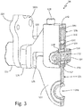
- FIG. 3 is a cross-sectional perspective view of mounting link 24 through section line 3-3 of FIG. 2 .
- FIG. 3 illustrates attachment plate 104 in its broken state, with shear neck 126 broken and fusibly separable section 122 accordingly detached from static section 120.
- FIG. 3 illustrates engine attachment bracket 102a (with engine attachment flange 114 and fastener support section 116), attachment plate 104 (with static section 120, fusibly separable section 122, pivot section 124, and shear necks 126), gearbox fastener 106, secondary retention sleeve 108, secondary retention fastener 112, and sleeve fastener 128 as described above with respect to FIG. 2 .
- FIG. 1 is a cross-sectional perspective view of mounting link 24 through section line 3-3 of FIG. 2 .
- FIG. 3 illustrates attachment plate 104 in its broken state, with shear neck 126 broken and fusibly separable section 122 accordingly detached from static section 120.
- FIG. 3 illustrates
- FIG. 3 further illustrates oversized fastener passage 132, bolt 134 and nut 136 of secondary retention fastener 112, secondary retention damper 138, separable section arch 140, sleeve end 142, sleeve sides 144 and 146, and retention fastener support passage 148.
- Static section 122 includes oversized fastener passage 140, a passage that allows secondary retention fastener 112 to pass through static section 122 with clearance that permits mechanical play along axes A 1 and A 2 , while still constraining static section 122 along these axes.
- secondary retention fastener 112 comprises bolt 134 with nut 136
- oversized fastener passage 132 contains secondary retention damper 138, an annular vibration and shock damping element disposed between secondary retention fastener 112 and walls of oversized fastener passage 132.
- engine attachment brackets 102 and attachment plate 104 can be formed of steel
- secondary retention damper 138 can be formed of rubber.
- secondary retention fastener 112 are separated from secondary retention damper 138 by gap g.
- retention secondary retention damper 138 can fill the entire space between secondary retention fastener 112 and fusibly separable section 122 of attachment plate 104.
- fusibly separable section 122 extends towards engine 100 in separable section arch 140 to surround oversized fastener passage 132.
- Retention sleeve 108 includes sleeve end 142 and sleeve sides 144 and 146.
- Sleeve sides 144 and 146 are plates extending parallel to and alongside faces of attachment plate 104, and are connected via sleeve end 142, which abuts a top edge of attachment plate 104 and can be arranged generally perpendicularly to sleeve sides 144 and 146.
- sleeve fasteners 128 pass through sleeve end 142 to secure secondary retention sleeve 108 to static section 120.
- Secondary retention sleeve 108 includes retention fastener support passage 148, a passage that fits and supports secondary retention fastener 112, thereby holding secondary retention fastener 112 at a fixed location relative to static section 120 of attachment plate 104.
- sleeve sides 144 and 146 snugly secure fusibly separable section 122 of attachment plate 104, thereby providing Coulomb damping against vibration along at least one of axes A 1 and A 2 .
- shear necks 126 connect static section 120 to fusibly separable section 122.
- Shear necks 126 are designed to shear at a known load magnitude corresponding to a maximum load transmission from engine 100 to gearbox 12. This can be accomplished by selecting an appropriately durable width and material for shear necks 126.
- shear necks 126 must be at least strong enough to withstand peak non-destructive impact loads such as low cycle loads from hard landings and other non-routine but expected shocks. These loads can, for example, reach 10-15 Gs. In at least some embodiments, shear necks 126 will not break until loads at least 10-25 times higher than expected low cycle loads. Very few loads experienced during aircraft engine operation reach these levels, but shocks due to blade-off events can be high enough to sever shear necks 126.
- Mounting link 24 rigidly constrains translation of gearbox 12 along axes A 1 and A 2 with respect to engine 100 under ordinary load conditions, including low occurrence, high magnitude shocks such as due to hard landings. Shear necks 126 fracture in the event of extreme shocks such as from blade-off events, permitting fusibly separable section 122 to move with respect to static section 120, while still constraining this movement via secondary retention sleeve 108 and secondary retention fastener 112. In this way, mounting link 24 limits or prevents damage that could otherwise be done to gearbox 12 and its attached peripherals by transmitting such extreme loads, while simultaneously helping to prevent gearbox 12 from detaching from engine 100.
- a gearbox mounting link between a gas turbine engine structure and a gearbox mounting location comprising: first and second engine attachment brackets configured to be secured to the gas turbine engine structure; an attachment plate rotatably secured to and extending between the first and second engine attachment brackets, the attachment plate comprising: a fusibly separable section configured to attach to the gearbox, so as to constrain motion of the gearbox in two degrees of freedom; a static section formed integrally with the fusibly separable section; and shear necks connecting the static section to the fusibly separable section; a secondary retention sleeve supported by and secured to the static section; and a secondary retention fastener supported by the secondary retention sleeve, and disposed through an oversized fastener passage through the fusibly separable section, thereby loosely retaining the fusibly separable section in at least one of the two degrees of freedom after separation of the fusibly separable section from the static section.
- the gearbox mounting link of the preceding paragraph can optionally include, additionally and/or alternatively, any one or more of the following features, configurations and/or additional components:
- a method of attaching a gearbox to a gas turbine engine structure comprising: attaching first and second engine attachment brackets to the gas turbine engine structure; rotatably securing an attachment plate between the first and second engine attachment brackets, the attachment plate including a static section supporting a secondary retention sleeve, a fusibly separable section, and shear necks connecting the fusibly separable section to the static section; rigidly attaching the fusibly separable section to the gearbox, such that the gearbox is retained along two degrees of freedom with respect to the gas turbine engine structure; securing a secondary retention fastener through the secondary retention sleeve and an oversized fastener passage of the fusibly separable section, such that the secondary retention fastener cannot abut the fusibly separable section so long as the shear necks remain intact.
- the method of the preceding paragraph can optionally include, additionally and/or alternatively, any one or more of the following features, configurations and/or additional components:
- An engine assembly comprising: an engine with an engine frame; a gearbox driven by the engine; and a gearbox mounting link connecting the gearbox to the engine frame, the gearbox mounting link comprising: first and second engine attachment brackets configured to be secured to the gas turbine engine structure; an attachment plate rotatably secured to and extending between the first and second engine attachment brackets, the attachment plate comprising: a fusibly separable section configured to attach to the gearbox, so as to constrain motion of the gearbox in two degrees of freedom; a static section formed integrally with the fusibly separable section; and shear necks connecting the static section to the fusibly separable section; a secondary retention sleeve supported by and secured to the static section; and a secondary retention fastener supported by the secondary retention sleeve, and disposed through an oversized fastener passage through the fusibly separable section, thereby loosely retaining the fusibly separable section in at least one of the two degrees of freedom after separation of the fusibly separable section from
- the engine assembly of the preceding paragraph can optionally include, additionally and/or alternatively, any one or more of the following features, configurations and/or additional components:
- any relative terms or terms of degree used herein such as “substantially”, “essentially”, “generally”, “approximately” and the like, should be interpreted in accordance with and subject to any applicable definitions or limits expressly stated herein. In all instances, any relative terms or terms of degree used herein should be interpreted to broadly encompass any relevant disclosed embodiments as well as such ranges or variations as would be understood by a person of ordinary skill in the art in view of the entirety of the present disclosure, such as to encompass ordinary manufacturing tolerance variations, incidental alignment variations, alignment or shape variations induced by thermal, rotational or vibrational operational conditions, and the like.
Landscapes
- Engineering & Computer Science (AREA)
- General Engineering & Computer Science (AREA)
- Mechanical Engineering (AREA)
- Chemical & Material Sciences (AREA)
- Combustion & Propulsion (AREA)
- Vibration Prevention Devices (AREA)
- Connection Of Plates (AREA)
- Turbine Rotor Nozzle Sealing (AREA)
Applications Claiming Priority (1)
| Application Number | Priority Date | Filing Date | Title |
|---|---|---|---|
| US15/069,454 US10006373B2 (en) | 2016-03-14 | 2016-03-14 | Two degree-of-constraint semi-fusible gearbox mounting link |
Publications (2)
| Publication Number | Publication Date |
|---|---|
| EP3219961A1 true EP3219961A1 (de) | 2017-09-20 |
| EP3219961B1 EP3219961B1 (de) | 2020-06-17 |
Family
ID=58231389
Family Applications (1)
| Application Number | Title | Priority Date | Filing Date |
|---|---|---|---|
| EP17158342.0A Active EP3219961B1 (de) | 2016-03-14 | 2017-02-28 | Getriebeaufhängungsverbindung mit zwei einschränkungsgraden |
Country Status (2)
| Country | Link |
|---|---|
| US (1) | US10006373B2 (de) |
| EP (1) | EP3219961B1 (de) |
Cited By (5)
| Publication number | Priority date | Publication date | Assignee | Title |
|---|---|---|---|---|
| EP3633164A1 (de) * | 2018-10-01 | 2020-04-08 | Hamilton Sundstrand Corporation | Getriebebefestigungselement einer gasturbine |
| EP4137672A1 (de) * | 2021-08-20 | 2023-02-22 | Raytheon Technologies Corporation | Montagesystem für hilfskomponenten für gasturbinenmotoren |
| US11655766B2 (en) | 2021-10-01 | 2023-05-23 | Raytheon Technologies Corporation | Auxiliary component mounting system for gas turbine engines |
| EP4406845A1 (de) * | 2023-01-25 | 2024-07-31 | Rolls-Royce plc | Montageanordnung für gasturbinenmotor |
| US12060835B2 (en) | 2021-08-20 | 2024-08-13 | Rtx Corporation | Laterally biased system for mounting auxiliary components to gas turbine engines |
Families Citing this family (3)
| Publication number | Priority date | Publication date | Assignee | Title |
|---|---|---|---|---|
| US10215100B2 (en) * | 2016-03-14 | 2019-02-26 | Hamilton Sundstrand Corporation | One degree-of-constraint semi-fusible gearbox mounting link |
| US10132245B2 (en) * | 2016-04-25 | 2018-11-20 | Hamilton Sundstrand Corporation | Fusible link with coulomb damping |
| US10358227B2 (en) * | 2017-08-15 | 2019-07-23 | The Boeing Company | Sideload reaction bearing |
Citations (3)
| Publication number | Priority date | Publication date | Assignee | Title |
|---|---|---|---|---|
| EP2559883A2 (de) * | 2011-08-19 | 2013-02-20 | United Technologies Corporation | Gasturbinenmotor-Zubehörbefestigung |
| US8561501B2 (en) * | 2011-05-31 | 2013-10-22 | United Technologies Corporation | Gearbox mount bracket |
| US20140174252A1 (en) * | 2012-12-23 | 2014-06-26 | United Technologies Corporation | Mount with an axial upstream linkage for conneting a gearbox to a turbine engine case |
Family Cites Families (13)
| Publication number | Priority date | Publication date | Assignee | Title |
|---|---|---|---|---|
| GB2129498B (en) | 1982-10-29 | 1986-04-03 | Rolls Royce | Mounting system for two coupled turboshaft gas turbine engines |
| GB9125011D0 (en) * | 1991-11-25 | 1992-01-22 | Rolls Royce Plc | A mounting arrangement for a gas turbine engine |
| US5860623A (en) * | 1995-05-03 | 1999-01-19 | The Boeing Company | Three link failsafe engine mount |
| US5921500A (en) * | 1997-10-08 | 1999-07-13 | General Electric Company | Integrated failsafe engine mount |
| US5927644A (en) * | 1997-10-08 | 1999-07-27 | General Electric Company | Double failsafe engine mount |
| US6212974B1 (en) | 1998-12-17 | 2001-04-10 | United Technologies Corporation | Variable stiffness positioning link for a gearbox |
| FR2894934B1 (fr) * | 2005-12-15 | 2009-11-13 | Airbus France | Attache arriere d'un moteur d'aeronef avec manille en attente et ressort pour un tel axe en attente |
| US20110239660A1 (en) | 2010-03-30 | 2011-10-06 | United Technologies Corporation | Mounting arrangement for gas turbine engine accessories and gearbox therefor |
| FR2977280B1 (fr) | 2011-06-28 | 2015-04-10 | Hispano Suiza Sa | Boitier perfectionne de relais d'accessoires d'une turbine a gaz |
| FR2977637B1 (fr) | 2011-07-04 | 2015-07-24 | Hispano Suiza Sa | Boitier de relais d'accessoires d'une turbine a gaz integrant des moyens de desaccouplement |
| US20130180262A1 (en) | 2012-01-18 | 2013-07-18 | Hung Duong | Gas turbine engine accessory gearbox |
| US9227734B2 (en) * | 2012-08-31 | 2016-01-05 | United Technologies Corporation | Secondary load path for gas turbine engine |
| WO2015041855A1 (en) * | 2013-09-19 | 2015-03-26 | United Technologies Corporation | Aircraft engine case shock mount |
-
2016
- 2016-03-14 US US15/069,454 patent/US10006373B2/en active Active
-
2017
- 2017-02-28 EP EP17158342.0A patent/EP3219961B1/de active Active
Patent Citations (3)
| Publication number | Priority date | Publication date | Assignee | Title |
|---|---|---|---|---|
| US8561501B2 (en) * | 2011-05-31 | 2013-10-22 | United Technologies Corporation | Gearbox mount bracket |
| EP2559883A2 (de) * | 2011-08-19 | 2013-02-20 | United Technologies Corporation | Gasturbinenmotor-Zubehörbefestigung |
| US20140174252A1 (en) * | 2012-12-23 | 2014-06-26 | United Technologies Corporation | Mount with an axial upstream linkage for conneting a gearbox to a turbine engine case |
Cited By (8)
| Publication number | Priority date | Publication date | Assignee | Title |
|---|---|---|---|---|
| EP3633164A1 (de) * | 2018-10-01 | 2020-04-08 | Hamilton Sundstrand Corporation | Getriebebefestigungselement einer gasturbine |
| US11015698B2 (en) | 2018-10-01 | 2021-05-25 | Hamilton Sundstrand Corporation | Gearbox mounting link |
| EP4137672A1 (de) * | 2021-08-20 | 2023-02-22 | Raytheon Technologies Corporation | Montagesystem für hilfskomponenten für gasturbinenmotoren |
| US11821329B2 (en) | 2021-08-20 | 2023-11-21 | Rtx Corporation | Auxiliary component mounting system for gas turbine engines |
| US12060835B2 (en) | 2021-08-20 | 2024-08-13 | Rtx Corporation | Laterally biased system for mounting auxiliary components to gas turbine engines |
| US11655766B2 (en) | 2021-10-01 | 2023-05-23 | Raytheon Technologies Corporation | Auxiliary component mounting system for gas turbine engines |
| EP4406845A1 (de) * | 2023-01-25 | 2024-07-31 | Rolls-Royce plc | Montageanordnung für gasturbinenmotor |
| US12479586B2 (en) | 2023-01-25 | 2025-11-25 | Rolls-Royce Plc | Fusible mounting assembly for gas turbine engine |
Also Published As
| Publication number | Publication date |
|---|---|
| US10006373B2 (en) | 2018-06-26 |
| US20170260910A1 (en) | 2017-09-14 |
| EP3219961B1 (de) | 2020-06-17 |
Similar Documents
| Publication | Publication Date | Title |
|---|---|---|
| US10006373B2 (en) | Two degree-of-constraint semi-fusible gearbox mounting link | |
| EP3242005B1 (de) | Getriebeaufhängungsverbindung sowie Verfahren zur Aufhängung eines Getriebes an eine Gasturbine | |
| EP3219963B1 (de) | Gesicherte getriebeaufhängungsverbindung mit zwei zwangsbedingungen | |
| EP3219962B1 (de) | Teilscherbare getriebeaufhängungsverbindung mit einem grad an restriktion | |
| EP2559883B1 (de) | Gasturbinenmotor-Getriebebefestigung | |
| US6357220B1 (en) | Gearbox accessory mount | |
| EP1008738B1 (de) | Getriebestütze mit geregelter Federkennlinie | |
| EP1010878B1 (de) | Gasturbine mit Getriebeaufhängung von verändlicher Steifheit | |
| JP4648645B2 (ja) | ガスタービン・エンジンを装着するための方法及び装置 | |
| US7448808B2 (en) | Arrangement of bearing supports for the rotating shaft of an aircraft engine and an aircraft engine fitted with such an arrangement | |
| US7452152B2 (en) | Tension decoupler device | |
| US7789344B2 (en) | Aircraft engine mounting device attachment arrangement | |
| EP1010879A2 (de) | Getriebeaufhängung | |
| EP2221249B1 (de) | Eine Schubkräfte aufnehmende Flugzeugtriebwerkaufhängung | |
| JPS63231094A (ja) | 振動絶縁エンジン取付け装置 | |
| EP3085982B1 (de) | Wellenbaugruppe mit zerbrechlicher kupplung und einer flexiblen kupplung | |
| US10132245B2 (en) | Fusible link with coulomb damping | |
| EP3633164B1 (de) | Getriebebefestigungselement einer gasturbinen | |
| CN101784811B (zh) | 用于飞行器机舱的振动缓冲器 | |
| US20220112819A1 (en) | Gas turbine engine bearing housing | |
| CN111511644A (zh) | 悬挂装置 | |
| CN111980958B (zh) | 一种熔断系统和航空发动机 | |
| US20070057128A1 (en) | Auxiliary power unit case flange to plate adapter | |
| CN101954972A (zh) | 设有桨叶保持装置的飞行器旋翼 | |
| US12209539B2 (en) | Fusible gearbox support with catcher pin systems and methods |
Legal Events
| Date | Code | Title | Description |
|---|---|---|---|
| PUAI | Public reference made under article 153(3) epc to a published international application that has entered the european phase |
Free format text: ORIGINAL CODE: 0009012 |
|
| STAA | Information on the status of an ep patent application or granted ep patent |
Free format text: STATUS: THE APPLICATION HAS BEEN PUBLISHED |
|
| AK | Designated contracting states |
Kind code of ref document: A1 Designated state(s): AL AT BE BG CH CY CZ DE DK EE ES FI FR GB GR HR HU IE IS IT LI LT LU LV MC MK MT NL NO PL PT RO RS SE SI SK SM TR |
|
| AX | Request for extension of the european patent |
Extension state: BA ME |
|
| STAA | Information on the status of an ep patent application or granted ep patent |
Free format text: STATUS: REQUEST FOR EXAMINATION WAS MADE |
|
| 17P | Request for examination filed |
Effective date: 20180320 |
|
| RBV | Designated contracting states (corrected) |
Designated state(s): AL AT BE BG CH CY CZ DE DK EE ES FI FR GB GR HR HU IE IS IT LI LT LU LV MC MK MT NL NO PL PT RO RS SE SI SK SM TR |
|
| GRAP | Despatch of communication of intention to grant a patent |
Free format text: ORIGINAL CODE: EPIDOSNIGR1 |
|
| STAA | Information on the status of an ep patent application or granted ep patent |
Free format text: STATUS: GRANT OF PATENT IS INTENDED |
|
| INTG | Intention to grant announced |
Effective date: 20190819 |
|
| GRAJ | Information related to disapproval of communication of intention to grant by the applicant or resumption of examination proceedings by the epo deleted |
Free format text: ORIGINAL CODE: EPIDOSDIGR1 |
|
| STAA | Information on the status of an ep patent application or granted ep patent |
Free format text: STATUS: REQUEST FOR EXAMINATION WAS MADE |
|
| GRAP | Despatch of communication of intention to grant a patent |
Free format text: ORIGINAL CODE: EPIDOSNIGR1 |
|
| STAA | Information on the status of an ep patent application or granted ep patent |
Free format text: STATUS: GRANT OF PATENT IS INTENDED |
|
| INTC | Intention to grant announced (deleted) | ||
| INTG | Intention to grant announced |
Effective date: 20200114 |
|
| GRAS | Grant fee paid |
Free format text: ORIGINAL CODE: EPIDOSNIGR3 |
|
| GRAA | (expected) grant |
Free format text: ORIGINAL CODE: 0009210 |
|
| STAA | Information on the status of an ep patent application or granted ep patent |
Free format text: STATUS: THE PATENT HAS BEEN GRANTED |
|
| AK | Designated contracting states |
Kind code of ref document: B1 Designated state(s): AL AT BE BG CH CY CZ DE DK EE ES FI FR GB GR HR HU IE IS IT LI LT LU LV MC MK MT NL NO PL PT RO RS SE SI SK SM TR |
|
| REG | Reference to a national code |
Ref country code: GB Ref legal event code: FG4D |
|
| REG | Reference to a national code |
Ref country code: CH Ref legal event code: EP |
|
| REG | Reference to a national code |
Ref country code: IE Ref legal event code: FG4D |
|
| REG | Reference to a national code |
Ref country code: DE Ref legal event code: R096 Ref document number: 602017018135 Country of ref document: DE |
|
| REG | Reference to a national code |
Ref country code: AT Ref legal event code: REF Ref document number: 1281572 Country of ref document: AT Kind code of ref document: T Effective date: 20200715 |
|
| PG25 | Lapsed in a contracting state [announced via postgrant information from national office to epo] |
Ref country code: FI Free format text: LAPSE BECAUSE OF FAILURE TO SUBMIT A TRANSLATION OF THE DESCRIPTION OR TO PAY THE FEE WITHIN THE PRESCRIBED TIME-LIMIT Effective date: 20200617 Ref country code: GR Free format text: LAPSE BECAUSE OF FAILURE TO SUBMIT A TRANSLATION OF THE DESCRIPTION OR TO PAY THE FEE WITHIN THE PRESCRIBED TIME-LIMIT Effective date: 20200918 Ref country code: NO Free format text: LAPSE BECAUSE OF FAILURE TO SUBMIT A TRANSLATION OF THE DESCRIPTION OR TO PAY THE FEE WITHIN THE PRESCRIBED TIME-LIMIT Effective date: 20200917 Ref country code: LT Free format text: LAPSE BECAUSE OF FAILURE TO SUBMIT A TRANSLATION OF THE DESCRIPTION OR TO PAY THE FEE WITHIN THE PRESCRIBED TIME-LIMIT Effective date: 20200617 Ref country code: SE Free format text: LAPSE BECAUSE OF FAILURE TO SUBMIT A TRANSLATION OF THE DESCRIPTION OR TO PAY THE FEE WITHIN THE PRESCRIBED TIME-LIMIT Effective date: 20200617 |
|
| REG | Reference to a national code |
Ref country code: LT Ref legal event code: MG4D |
|
| REG | Reference to a national code |
Ref country code: NL Ref legal event code: MP Effective date: 20200617 |
|
| PG25 | Lapsed in a contracting state [announced via postgrant information from national office to epo] |
Ref country code: RS Free format text: LAPSE BECAUSE OF FAILURE TO SUBMIT A TRANSLATION OF THE DESCRIPTION OR TO PAY THE FEE WITHIN THE PRESCRIBED TIME-LIMIT Effective date: 20200617 Ref country code: BG Free format text: LAPSE BECAUSE OF FAILURE TO SUBMIT A TRANSLATION OF THE DESCRIPTION OR TO PAY THE FEE WITHIN THE PRESCRIBED TIME-LIMIT Effective date: 20200917 Ref country code: HR Free format text: LAPSE BECAUSE OF FAILURE TO SUBMIT A TRANSLATION OF THE DESCRIPTION OR TO PAY THE FEE WITHIN THE PRESCRIBED TIME-LIMIT Effective date: 20200617 Ref country code: LV Free format text: LAPSE BECAUSE OF FAILURE TO SUBMIT A TRANSLATION OF THE DESCRIPTION OR TO PAY THE FEE WITHIN THE PRESCRIBED TIME-LIMIT Effective date: 20200617 |
|
| REG | Reference to a national code |
Ref country code: AT Ref legal event code: MK05 Ref document number: 1281572 Country of ref document: AT Kind code of ref document: T Effective date: 20200617 |
|
| PG25 | Lapsed in a contracting state [announced via postgrant information from national office to epo] |
Ref country code: AL Free format text: LAPSE BECAUSE OF FAILURE TO SUBMIT A TRANSLATION OF THE DESCRIPTION OR TO PAY THE FEE WITHIN THE PRESCRIBED TIME-LIMIT Effective date: 20200617 Ref country code: NL Free format text: LAPSE BECAUSE OF FAILURE TO SUBMIT A TRANSLATION OF THE DESCRIPTION OR TO PAY THE FEE WITHIN THE PRESCRIBED TIME-LIMIT Effective date: 20200617 |
|
| PG25 | Lapsed in a contracting state [announced via postgrant information from national office to epo] |
Ref country code: EE Free format text: LAPSE BECAUSE OF FAILURE TO SUBMIT A TRANSLATION OF THE DESCRIPTION OR TO PAY THE FEE WITHIN THE PRESCRIBED TIME-LIMIT Effective date: 20200617 Ref country code: SM Free format text: LAPSE BECAUSE OF FAILURE TO SUBMIT A TRANSLATION OF THE DESCRIPTION OR TO PAY THE FEE WITHIN THE PRESCRIBED TIME-LIMIT Effective date: 20200617 Ref country code: ES Free format text: LAPSE BECAUSE OF FAILURE TO SUBMIT A TRANSLATION OF THE DESCRIPTION OR TO PAY THE FEE WITHIN THE PRESCRIBED TIME-LIMIT Effective date: 20200617 Ref country code: AT Free format text: LAPSE BECAUSE OF FAILURE TO SUBMIT A TRANSLATION OF THE DESCRIPTION OR TO PAY THE FEE WITHIN THE PRESCRIBED TIME-LIMIT Effective date: 20200617 Ref country code: PT Free format text: LAPSE BECAUSE OF FAILURE TO SUBMIT A TRANSLATION OF THE DESCRIPTION OR TO PAY THE FEE WITHIN THE PRESCRIBED TIME-LIMIT Effective date: 20201019 Ref country code: CZ Free format text: LAPSE BECAUSE OF FAILURE TO SUBMIT A TRANSLATION OF THE DESCRIPTION OR TO PAY THE FEE WITHIN THE PRESCRIBED TIME-LIMIT Effective date: 20200617 Ref country code: RO Free format text: LAPSE BECAUSE OF FAILURE TO SUBMIT A TRANSLATION OF THE DESCRIPTION OR TO PAY THE FEE WITHIN THE PRESCRIBED TIME-LIMIT Effective date: 20200617 Ref country code: IT Free format text: LAPSE BECAUSE OF FAILURE TO SUBMIT A TRANSLATION OF THE DESCRIPTION OR TO PAY THE FEE WITHIN THE PRESCRIBED TIME-LIMIT Effective date: 20200617 |
|
| PG25 | Lapsed in a contracting state [announced via postgrant information from national office to epo] |
Ref country code: IS Free format text: LAPSE BECAUSE OF FAILURE TO SUBMIT A TRANSLATION OF THE DESCRIPTION OR TO PAY THE FEE WITHIN THE PRESCRIBED TIME-LIMIT Effective date: 20201017 Ref country code: SK Free format text: LAPSE BECAUSE OF FAILURE TO SUBMIT A TRANSLATION OF THE DESCRIPTION OR TO PAY THE FEE WITHIN THE PRESCRIBED TIME-LIMIT Effective date: 20200617 Ref country code: PL Free format text: LAPSE BECAUSE OF FAILURE TO SUBMIT A TRANSLATION OF THE DESCRIPTION OR TO PAY THE FEE WITHIN THE PRESCRIBED TIME-LIMIT Effective date: 20200617 |
|
| REG | Reference to a national code |
Ref country code: DE Ref legal event code: R097 Ref document number: 602017018135 Country of ref document: DE |
|
| PLBE | No opposition filed within time limit |
Free format text: ORIGINAL CODE: 0009261 |
|
| STAA | Information on the status of an ep patent application or granted ep patent |
Free format text: STATUS: NO OPPOSITION FILED WITHIN TIME LIMIT |
|
| PG25 | Lapsed in a contracting state [announced via postgrant information from national office to epo] |
Ref country code: DK Free format text: LAPSE BECAUSE OF FAILURE TO SUBMIT A TRANSLATION OF THE DESCRIPTION OR TO PAY THE FEE WITHIN THE PRESCRIBED TIME-LIMIT Effective date: 20200617 |
|
| 26N | No opposition filed |
Effective date: 20210318 |
|
| PG25 | Lapsed in a contracting state [announced via postgrant information from national office to epo] |
Ref country code: SI Free format text: LAPSE BECAUSE OF FAILURE TO SUBMIT A TRANSLATION OF THE DESCRIPTION OR TO PAY THE FEE WITHIN THE PRESCRIBED TIME-LIMIT Effective date: 20200617 |
|
| PG25 | Lapsed in a contracting state [announced via postgrant information from national office to epo] |
Ref country code: MC Free format text: LAPSE BECAUSE OF FAILURE TO SUBMIT A TRANSLATION OF THE DESCRIPTION OR TO PAY THE FEE WITHIN THE PRESCRIBED TIME-LIMIT Effective date: 20200617 |
|
| REG | Reference to a national code |
Ref country code: BE Ref legal event code: MM Effective date: 20210228 |
|
| PG25 | Lapsed in a contracting state [announced via postgrant information from national office to epo] |
Ref country code: CH Free format text: LAPSE BECAUSE OF NON-PAYMENT OF DUE FEES Effective date: 20210228 Ref country code: LU Free format text: LAPSE BECAUSE OF NON-PAYMENT OF DUE FEES Effective date: 20210228 Ref country code: LI Free format text: LAPSE BECAUSE OF NON-PAYMENT OF DUE FEES Effective date: 20210228 |
|
| PG25 | Lapsed in a contracting state [announced via postgrant information from national office to epo] |
Ref country code: IE Free format text: LAPSE BECAUSE OF NON-PAYMENT OF DUE FEES Effective date: 20210228 |
|
| PG25 | Lapsed in a contracting state [announced via postgrant information from national office to epo] |
Ref country code: BE Free format text: LAPSE BECAUSE OF NON-PAYMENT OF DUE FEES Effective date: 20210228 |
|
| PG25 | Lapsed in a contracting state [announced via postgrant information from national office to epo] |
Ref country code: HU Free format text: LAPSE BECAUSE OF FAILURE TO SUBMIT A TRANSLATION OF THE DESCRIPTION OR TO PAY THE FEE WITHIN THE PRESCRIBED TIME-LIMIT; INVALID AB INITIO Effective date: 20170228 |
|
| P01 | Opt-out of the competence of the unified patent court (upc) registered |
Effective date: 20230522 |
|
| PG25 | Lapsed in a contracting state [announced via postgrant information from national office to epo] |
Ref country code: CY Free format text: LAPSE BECAUSE OF FAILURE TO SUBMIT A TRANSLATION OF THE DESCRIPTION OR TO PAY THE FEE WITHIN THE PRESCRIBED TIME-LIMIT Effective date: 20200617 |
|
| PG25 | Lapsed in a contracting state [announced via postgrant information from national office to epo] |
Ref country code: MK Free format text: LAPSE BECAUSE OF FAILURE TO SUBMIT A TRANSLATION OF THE DESCRIPTION OR TO PAY THE FEE WITHIN THE PRESCRIBED TIME-LIMIT Effective date: 20200617 |
|
| PG25 | Lapsed in a contracting state [announced via postgrant information from national office to epo] |
Ref country code: MT Free format text: LAPSE BECAUSE OF FAILURE TO SUBMIT A TRANSLATION OF THE DESCRIPTION OR TO PAY THE FEE WITHIN THE PRESCRIBED TIME-LIMIT Effective date: 20200617 |
|
| PG25 | Lapsed in a contracting state [announced via postgrant information from national office to epo] |
Ref country code: TR Free format text: LAPSE BECAUSE OF FAILURE TO SUBMIT A TRANSLATION OF THE DESCRIPTION OR TO PAY THE FEE WITHIN THE PRESCRIBED TIME-LIMIT Effective date: 20200617 |
|
| PGFP | Annual fee paid to national office [announced via postgrant information from national office to epo] |
Ref country code: GB Payment date: 20260121 Year of fee payment: 10 |
|
| PGFP | Annual fee paid to national office [announced via postgrant information from national office to epo] |
Ref country code: DE Payment date: 20260121 Year of fee payment: 10 |
|
| PGFP | Annual fee paid to national office [announced via postgrant information from national office to epo] |
Ref country code: FR Payment date: 20260121 Year of fee payment: 10 |