EP3220030B1 - Élément d'étanchéité d'une conduite par rapport à une ouverture - Google Patents
Élément d'étanchéité d'une conduite par rapport à une ouverture Download PDFInfo
- Publication number
- EP3220030B1 EP3220030B1 EP17158445.1A EP17158445A EP3220030B1 EP 3220030 B1 EP3220030 B1 EP 3220030B1 EP 17158445 A EP17158445 A EP 17158445A EP 3220030 B1 EP3220030 B1 EP 3220030B1
- Authority
- EP
- European Patent Office
- Prior art keywords
- sealing
- tensioning
- section
- bodies
- stop
- Prior art date
- Legal status (The legal status is an assumption and is not a legal conclusion. Google has not performed a legal analysis and makes no representation as to the accuracy of the status listed.)
- Active
Links
Images




Classifications
-
- F—MECHANICAL ENGINEERING; LIGHTING; HEATING; WEAPONS; BLASTING
- F16—ENGINEERING ELEMENTS AND UNITS; GENERAL MEASURES FOR PRODUCING AND MAINTAINING EFFECTIVE FUNCTIONING OF MACHINES OR INSTALLATIONS; THERMAL INSULATION IN GENERAL
- F16L—PIPES; JOINTS OR FITTINGS FOR PIPES; SUPPORTS FOR PIPES, CABLES OR PROTECTIVE TUBING; MEANS FOR THERMAL INSULATION IN GENERAL
- F16L5/00—Devices for use where pipes, cables or protective tubing pass through walls or partitions
- F16L5/02—Sealing
- F16L5/08—Sealing by means of axial screws compressing a ring or sleeve
-
- F—MECHANICAL ENGINEERING; LIGHTING; HEATING; WEAPONS; BLASTING
- F16—ENGINEERING ELEMENTS AND UNITS; GENERAL MEASURES FOR PRODUCING AND MAINTAINING EFFECTIVE FUNCTIONING OF MACHINES OR INSTALLATIONS; THERMAL INSULATION IN GENERAL
- F16L—PIPES; JOINTS OR FITTINGS FOR PIPES; SUPPORTS FOR PIPES, CABLES OR PROTECTIVE TUBING; MEANS FOR THERMAL INSULATION IN GENERAL
- F16L5/00—Devices for use where pipes, cables or protective tubing pass through walls or partitions
- F16L5/02—Sealing
- F16L5/025—Sealing the pipe being movable
-
- H—ELECTRICITY
- H02—GENERATION; CONVERSION OR DISTRIBUTION OF ELECTRIC POWER
- H02G—INSTALLATION OF ELECTRIC CABLES OR LINES, OR OF COMBINED OPTICAL AND ELECTRIC CABLES OR LINES
- H02G3/00—Installations of electric cables or lines or protective tubing therefor in or on buildings, equivalent structures or vehicles
- H02G3/22—Installations of cables or lines through walls, floors or ceilings, e.g. into buildings
Definitions
- the invention relates to a sealing insert for sealing a line against a recess in a wall section of a building wall, according to claim 1.
- a building is regularly supplied with media through underground lines.
- the building wall In order to introduce these lines into the building, the building wall must be penetrated.
- several wall sections usually have a recess through which one or more lines extend.
- the building wall is provided with a seal in order to protect the people, objects and building facilities in the building from external influences, in particular penetrating water and moisture.
- the recesses in the wall sections of the building wall thus interrupt the building seal.
- sealing inserts of the generic type are used. The sealing of the building is restored by using such sealing inserts.
- Sealing inserts of the generic type have an outer and an inner sealing section.
- the outer sealing section serves for sealing against the recess, the inner sealing section serving for sealing against the line.
- sealing inserts have tensioning devices which simultaneously tension both the outer sealing section with the recess and the inner sealing section with the line.
- the bracing of the outer sealing section and the bracing of the inner sealing section are thus dependent on one another. Because of this dependency, the possible uses of corresponding sealing inserts are limited, so that different sealing inserts often have to be used to brace different cable types in order to produce bracing in the desired range of values.
- connection piece for sealing a line against a container wall.
- the connection piece comprises an annular sealing flange which is braced on the outside around the recess against the container wall.
- the sealing flange is connected to a plurality of sleeve-like sections via a bend-back section, each of which is braced via hose clamps to the outside of a line pushed through a section.
- sealing inserts In order to be able to use sealing inserts for sealing against lines of different diameters, known sealing inserts have several inner sealing sections of different diameters. Thus, depending on requirements, the suitable sealing section can be used for sealing against a line of a specific diameter.
- EP 2 447 583 A1 relates to a sealing device for guiding a line through a wall section.
- the sealing device comprises a sealing body which is inserted into an opening in the wall section and is deformed by means of a clamping body.
- the sealing body comprises several sealing cones that can be plugged into one another, each with a conical section for sealing lines with different diameters.
- a second sealing cone is connected to a first sealing cone in a predetermined breaking section by means of a predetermined breaking point.
- a third sealing cone is connected to the second sealing cone in a predetermined breaking section.
- Sealing inserts which have both a decoupling of the outer sealing section from the inner sealing section and several inner sealing sections of different diameters, are not able to accommodate axial or radial movements of the line against which the sealing insert seals. In practice, however, line movements occur even after the installation of a sealing insert, which must be absorbed by the sealing insert used without the sealing effect being impaired.
- DE 295 17 409 U1 shows a cable guide with a protective tube, which comprises a sealing device with a rubber element assigned to the protective tube.
- a shrink tube is used which, through the action of heat, is applied in a sealing manner to the outside of the line guided through the protective tube and to the outside of the protective tube.
- the object of the present invention is consequently to provide a sealing insert which is improved over the known sealing inserts.
- At least one clamping body of the first clamping device has a support surface which supports the sealing body in the radial direction inward, whereby an expansion of the sealing body in the radial direction inward is prevented or significantly reduced, so that from the entire or at least a large part of the for bracing the Outer sealing section applied tension force a radial expansion of the sealing body is effected outward, and adjacent inner sealing sections by means of Web sections are connected. Because the compensator section is flexible and variable in length, relative movements of the sealed line with respect to the recess can be absorbed, ie compensated, without the sealing effect of the sealing insert being impaired.
- the compensator section preferably enables a relative movement between the outer sealing section and the inner sealing section in the axial direction and / or in the radial direction without the sealing effect being impaired.
- the compensator section preferably enables the angle of incidence between the outer sealing section and the inner sealing section to be changed without the sealing effect being impaired.
- the sealing insert according to the invention has several inner sealing sections for sealing against lines of different diameters.
- the possible uses of the sealing insert are considerably expanded by the multiple inner sealing sections of different diameters.
- One and the same sealing insert can thus be used for sealing a recess against different lines. Since a large number of different lines have to be sealed against recesses in wall sections in the sealing of buildings, there is thus a considerable cost saving, since the production of different sealing inserts is no longer necessary. Furthermore, the risk of improper installation or improper assembly of the sealing insert is reduced, since the responsible fitter is relieved of the previously required selection of a suitable sealing insert from a large number of different sealing insert types.
- the sealing insert according to the invention is further advantageously developed in that the compensator section is designed to be rotationally symmetrical. Due to the rotationally symmetrical design of the compensator section, an axial movement of the line, against which the sealing insert seals, leads to a uniform deformation of the compensator section. This results in an even load on the compensator section over the entire circumference, so that the risk of damage due to additional loading or overloading occurring in certain areas is reduced.
- the compensator section comprises a single or multiple folded membrane.
- the length variability of the compensator section can be achieved in a particularly simple manner by folding the membrane. Next The length variability is also achieved by the membrane folding a flexibility which a radial movement and a change in inclination of the line, against which the sealing insert seals, can be absorbed and thus compensated.
- the compensator section is preferably designed in one piece with the sealing body, which carries the outer sealing section and the inner sealing sections. If the sealing body is formed in several parts, the compensator section is preferably formed in one piece with a sealing body part.
- the one-piece design of the compensator section with the sealing body or a sealing body part avoids the production of a separate part which carries the compensator section.
- the assembly and installation of the sealing insert is simplified by the one-piece design of the compensator section with the sealing body or a sealing body part.
- the compensator section has a plurality of coaxially arranged ring sections of different diameters, with adjacent ring sections preferably being connected by means of a curved fold section,
- the plurality of inner sealing sections have essentially annular cross-sections of different diameters and are arranged essentially coaxially to one another.
- a preferred embodiment of the sealing insert according to the invention has a second tensioning device for tensioning an inner sealing section of the plurality of inner sealing sections.
- the outer sealing section is preferably decoupled from the inner sealing sections in order to avoid any influence by the second tensioning device. There is thus a complete decoupling of the outer sealing section and the inner sealing sections with regard to their bracing.
- the second tensioning device is preferably designed as a circumferential bracing cuff, the flexible steel band of which runs around the sealing body which carries the inner sealing sections, whereby the diameter of the circumferential steel band can be adjusted by a locking device, such as a clamp or buckle.
- the sealing insert according to the invention is further developed advantageously in that the plurality of inner sealing sections are arranged axially offset from one another.
- the axial offset of the inner sealing sections reduces the necessary adjustment path of the second tensioning device, since the second tensioning device can be placed directly on the section of the sealing body which carries the inner sealing section required for sealing. Due to the axial spacing of the inner sealing sections, the individual sealing sections are also more easily accessible to the fitter, which simplifies the handling of the sealing insert and its assembly.
- adjacent inner sealing sections of the sealing insert according to the invention are connected by means of web sections.
- the web sections which connect adjacent inner sealing sections, are preferably accessible from the outside.
- the web sections are preferably designed in such a way that they can be pierced by the fitter using tools. After the web section has been pierced at one point, the web section can be torn by applying tensile force to one or more inner sealing sections to be detached. Pointed and at the same time blurred tools, such as screwdrivers for example, are preferred for piercing the web sections, since their use does not involve the risk of inadvertently cutting into a sealing section.
- the web sections are preferably designed in such a way that when a web section is buckled, a crack is produced within the kinked web section.
- the crack within the web section can be widened by the application of tensile force to one or more inner sealing sections to be detached along the web section.
- one or more sealing sections can thus be detached from the sealing body.
- inner sealing sections with a diameter which is too small for sealing the line to be sealed can be removed from the sealing body, so that the line to be sealed can be sealed with an inner sealing section which has a suitable diameter.
- the web sections are designed in such a way that they can be torn directly by the application of tensile force. In this way, the sealing insert can be quickly adapted to the line to be sealed without using tools. Because the web sections can be torn by the application of tensile force, the The use of additional tools such as screwdrivers is completely avoided. The adaptation of the sealing insert to the line to be sealed is thus further simplified.
- the sealing body is preferably designed in one piece or in several pieces. If the sealing body is designed in one piece, the one-piece sealing body carries both the inner sealing section and the outer sealing section. If the sealing body is designed in several parts, one or more sealing body parts carry the inner sealing section and one or more further sealing body parts carry the outer sealing section. A bracing area of the sealing body part, which carries the inner sealing sections, can preferably be clamped between the sealing body parts or above or below the sealing body which carry the outer sealing section.
- the first tensioning device of the sealing insert according to the invention has two tensioning bodies, which can be moved relative to one another, for tensioning the outer sealing section.
- the clamping bodies of the first clamping device preferably each have a plurality of, in particular 4, 5 or 6 through bores. Screws preferably extend through the through bores, the tensioning bodies preferably being braced by means of corresponding nuts.
- the second tensioning device has two tensioning bodies that can be moved relative to one another for tensioning an inner sealing section of the plurality of inner sealing sections.
- At least one clamping body of the first clamping device has a support surface which supports the sealing body in the radial direction inward, which carries the sealing section.
- Both clamping bodies of the first clamping device preferably have a support surface which supports the sealing body inward in the radial direction.
- the radial inward support of the sealing body prevents or at least significantly reduces expansion of the sealing body in the radial direction inward.
- the support surface of the at least one clamping body of the first clamping device comprises a support section running parallel to the outer sealing section.
- the support surface of the at least one clamping body of the first clamping device comprises a support section running at an incline to the outer sealing section.
- the support section of the support surface of the at least one clamping body of the first clamping device which is inclined to the outer sealing section, leads to a further reduction in the necessary bracing force, since the expansion of the sealing body in the radial direction outward is further promoted by the inclination of the support section.
- a stop preferably limits the tensioning of the outer sealing section.
- the fact that the sealing insert is equipped with a stop results in a structural limitation of the bracing of the outer sealing section.
- a screw connection can thus, for example, be tightened intuitively "to the stop", so that there is no need to use special tools. In this way, the risk of insufficient or excessive tensioning of the outer sealing section is considerably reduced.
- a stop preferably limits the tensioning of an inner sealing section of the plurality of inner sealing sections.
- the clamping bodies of the first clamping device each have a pressing surface, the pressing surfaces being movable relative to one another.
- a shape-variable sealing body is formed between the pressing surfaces, the sealing body carrying the outer sealing section.
- the pressing surfaces of the clamping bodies of the first clamping device are preferably aligned perpendicular to the axis of movement of the clamping bodies of the first clamping device.
- the pressing surfaces of the clamping bodies of the first clamping device have an angle in the range from 35 to 55 degrees with respect to a plane which is oriented perpendicular to the axis of movement of the clamping bodies of the first clamping device. In a particularly preferred embodiment, this angle corresponds to approximately 45 degrees.
- the clamping bodies of the first clamping device are preferably made of plastic or metal.
- the shape-variable sealing body is preferably formed from an elastomer material.
- the outer sealing section has a cylindrical outer jacket surface.
- the clamping bodies of the first clamping device each have a stop surface, the stop surfaces being movable relative to one another. In a stop position, the stop surfaces strike either against one another or against the sealing body.
- the stop surfaces and the pressing surfaces of the clamping bodies of the first clamping device are operatively connected, so that a relative movement of the pressing surfaces of the clamping bodies of the first clamping device leads to a relative movement of the stop surfaces of the clamping bodies of the first clamping device.
- This can be achieved in a simple way by that the clamping bodies of the first clamping device are each formed in one piece and the stop surface and the pressing surface of a clamping body of the first clamping device are formed on its surface.
- a particularly preferred embodiment of the sealing insert according to the invention has one or more movable stop bodies which each strike a stop surface in a stop position.
- a plurality of stop bodies are arranged on a circular path, adjacent stop bodies arranged next to one another being equidistant from one another.
- Preferably four, five, six, seven or eight essentially identical stop bodies are arranged on a circular path around a central central axis of the sealing insert.
- the stop surfaces against which the one or more stop bodies strike are preferably formed on one of the clamping bodies of the first clamping device.
- the sealing insert according to the invention is further advantageously developed in that the stop of the first tensioning device is adjustable.
- the adjustability of the stop of the first tensioning device is preferably achieved by selecting stop bodies of a suitable length or by changing the position of the stop surface for the stop bodies.
- the sealing device preferably has one or more exchangeable stop bushings, the one or more stop bushings each carrying a stop surface for a stop body.
- the stop bushings used are preferably identical.
- the stop bushings have a bottom section which forms the stop surface for a stop body.
- the clamping bodies of the first clamping device or the stop bushings preferably have slots through which further base elements can be inserted. In this way, the position of the stop surfaces can be varied so that the tensioning device can be adjusted.
- the sealing insert according to the invention is further advantageously developed in that the pressing surfaces of the clamping bodies of the first clamping device are operatively connected to the one or more stop bodies, so that a movement of the one or more stop bodies causes a relative movement of the pressing surfaces of the clamping bodies of the first clamping device.
- it causes a linear movement or a rotational movement of the one or more stop bodies a relative movement of the pressing surfaces of the clamping bodies of the first clamping device.
- the relative movement of the pressing surfaces of the clamping bodies of the first clamping device is, for example, an approach of the clamping bodies of the first clamping device to one another so that the sealing body arranged between the clamping bodies of the first clamping device is compressed.
- the relative movement of the pressing surfaces of the clamping bodies of the first clamping device can also lead to an increase in the distance between the pressing surfaces of the clamping bodies of the first clamping device, so that the sealing body arranged between the pressing surfaces of the clamping bodies of the first clamping device is relaxed when the one or more stop bodies are moved and thus the compression is reduced or canceled.
- a clamping body of the first clamping device has one or more threaded bores.
- the one or more stop bodies each comprise a threaded section which can be screwed to a threaded bore.
- the one or more stop bodies are preferably designed as screws and extend through a through hole in a clamping body of the first clamping device and engage in the threaded section of a threaded hole in the other clamping body of the first clamping device. A tightening and thus a rotational movement of the one or more stop bodies thus causes the clamping bodies of the first tensioning device to move relative to one another with the pressing surfaces.
- the one or more threaded bores each have a blind hole, the bottom of the blind hole being designed as a stop surface for the stop body.
- the one or more stop bodies are preferably designed as screws, the end face of the screw opposite the screw head striking the base of the blind hole. The stop for limiting the tension is thus achieved by striking the end face of the screw opposite the screw head in the bottom of the blind hole.
- the sealing body which carries the outer sealing section has one or more circumferential elevations.
- the sealing body that carries the inner sealing sections has one or more circumferential elevations on.
- the circumferential elevations are preferably adapted for guiding a tensioning device, for example for guiding a bracing collar.
- the circumferential elevations can serve the responsible fitter as an indication of the correct positioning of a clamping device.
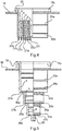
- the sealing insert 1 has an outer sealing section 3 for sealing against a recess and three inner sealing sections 5 ( Fig. 5 ) of different diameters for sealing against lines of different diameters. Furthermore, the sealing insert 1 comprises a first tensioning device 7 for tensioning the outer sealing section 3, the inner sealing sections being decoupled from the outer sealing section 3 in order to avoid being influenced by the first tensioning device 7.
- the first clamping device 7 has two clamping bodies 11 a, 11 b, which can be moved relative to one another, for clamping the outer sealing section 3.
- the clamping bodies 11a, 11b of the first clamping device 7 each have a pressing surface 13a, b ( Fig. 2a ), wherein the pressing surfaces can be moved relative to one another and a shape-variable sealing body 15 made of an elastomer material, which carries the outer sealing section 3, is arranged between the pressing surfaces.
- the clamping bodies 11a, 11b each have four through bores. Screws 12a-12d extend through the through-bores, the clamping bodies 11a, 11b being braced by means of corresponding nuts 14a-14d.
- the three inner sealing sections can each be clamped fluid-tight with a line by means of a second clamping device 9.
- the three inner sealing sections have annular cross sections of different diameters and are coaxial arranged to each other.
- the sealing body 15 has two circumferential elevations 25a, 25b in each of the areas of the inner sealing sections. The circumferential elevations 25a, 25b serve to align the second tensioning device 9.
- the three inner sealing sections 5 are axially offset from one another.
- the three inner sealing sections 5 are connected to one another via web sections 27a, 27b.
- a third web 27c serves as a blind cover.
- the web sections 27a, 27b, c can be pierced by means of a tool, such as for example a screwdriver, and then torn by applying tensile force.
- a handle 28 is formed on the third web 27c and can be gripped manually to remove the blind cover.
- the web sections 27a-c can be separated by means of a respective predetermined breaking point 30a, b, c.
- the first tensioning device 7 has two tensioning bodies 11a, 11b that can be moved relative to one another for tensioning the outer sealing section 3 by means of the pressing surfaces 13a, b.
- the sealing body 15a, 15b is designed in several parts.
- the sealing body parts 15a, 15b carry the outer sealing section 3.
- Between the sealing body parts 15a, 15b there is a bracing area of a further sealing body part (see, for example, reference symbol 15c in FIG FIGS. 4 and 5 , and 115c in Fig. 8 ) can be clamped, the further sealing body part carrying the inner sealing sections.
- the clamping bodies 11a, 11b of the first clamping device 7 each have a support surface which supports the sealing body 15a, 15b in the radial direction inward.
- the support surfaces comprise support sections 29a, 29b running parallel to the outer sealing section 3.
- the clamping bodies 11a, 11b each have four through bores. Screws 12a, 12b extend through the through-bores, the clamping bodies 11a, 11b being braced by means of corresponding nuts 14a, 14b.
- the first clamping device 7 also has two clamping bodies 11a, 11b which can be moved relative to one another for clamping the outer sealing section 3 by means of the pressing surface 13a, b.
- the sealing body 15 carries the outer sealing section 3.
- Above or below the sealing body 15 is a bracing area of a further sealing body part (see for example reference symbol 15c in FIG FIGS. 4 and 5 , and 115c in Fig. 8 ) can be clamped, the further sealing body part carrying the inner sealing sections.
- the clamping bodies 11a, 11b of the first clamping device 7 each have a support surface which supports the sealing body 15 in the radial direction inward.
- the support surfaces comprise support sections 29a, 29b running parallel to the outer sealing section 3 and inclined to the outer sealing section extending support sections 31a, 31b.
- the clamping bodies 11a, 11b each have four through bores. Screws 12a, 12b extend through the through-bores, the clamping bodies 11a, 11b being braced by means of corresponding nuts 14a, 14b.
- Fig. 4 shows a first embodiment of an above-mentioned further sealing body part 15c.
- the bracing area 16 of the sealing body part 15c is connected to the inner sealing sections 5 via a flexible compensator section 33 of variable length.
- the bracing area 16 is between further sealing body parts (see for example reference numbers 15a, b in Figures 2a and 2b ) or above or below a sealing body (see, for example, reference symbol 15 in Figures 3a and 3b ) can be clamped.
- the compensator section 33 is rotationally symmetrical and comprises a double-folded membrane.
- the six inner sealing sections 5 have ring-shaped cross sections of different diameters and are arranged coaxially to one another.
- the sealing body part 15c has two circumferential elevations 25a, 25b in the area of the outermost inner sealing section 5.
- the circumferential elevations 25a, 25b serve to align a clamping device.
- the six inner sealing sections 5 are arranged next to one another in the radial direction and are connected to one another with web sections 27a to 27f.
- the web sections 27a to 27f can be pierced by means of a tool, such as a screwdriver, and then torn by applying tensile force.
- Fig. 5 shows a further embodiment of the above-mentioned further sealing body part 15c.
- the bracing area 16 of the further sealing body part 15c is connected to the inner sealing sections 5 via a flexible compensator section 33 of variable length.
- the bracing area 16 is between further sealing body parts (see Figures 2a and 2b ) or above or below a sealing body (see Figures 3a and 3b ) can be clamped.
- the compensator section 33 is rotationally symmetrical and comprises a double-folded membrane.
- the three inner sealing sections 5 have ring-shaped cross sections of different diameters and are arranged coaxially to one another.
- the sealing body part 15c has two circumferential elevations 25a, 25b in each of the regions of the inner sealing sections 5.
- the circumferential elevations 25a, 25b serve to align a clamping device.
- the three inner sealing sections 5 are arranged axially offset from one another and are connected to one another by web sections 27a, 27b.
- a third web section 27c forms a blind cover.
- the web sections 27a, 27b, 27c are at respective predetermined breaking points 30a, b, c by means of a tool, such as a screwdriver pierceable and then tearable by applying tensile force.
- a handle 28 is formed on the third web section 27c and can be manually grasped by the fitter of the sealing insert 1 in order to remove the blind cover.
- the sealing insert 1 has an outer sealing section 3 for sealing against a recess and two inner sealing sections 5 for sealing against lines of different diameters.
- the sealing insert 1 further comprises a first tensioning device 7 for tensioning the outer sealing section 3, the inner sealing sections 5 being decoupled from the outer sealing section 3 in order to avoid being influenced by the first tensioning device 7.
- the first clamping device 7 has two clamping bodies 11 a, 11 b, which can be moved relative to one another, for clamping the outer sealing section 3.
- Both clamping bodies 11a, 11b of the first clamping device 7 have a support surface which supports the sealing body 15 in the radial direction inward.
- the support surfaces of the two clamping bodies 11a, 11b each comprise a support section 29a, 29b running parallel to the outer sealing section 3
- the outer sealing section 3 is connected to the inner sealing sections 5 via a flexible compensator section 33 of variable length.
- the compensator section 33 is rotationally symmetrical and comprises a double-folded membrane.
- the clamping bodies 11a, 11b of the first clamping device 7 each have a pressing surface 13a, 13b.
- the pressing surfaces 13a, 13b can be moved relative to one another, a shape-changeable sealing body 15, which carries the outer sealing section 3, being arranged between the pressing surfaces 13a, 13b.
- the shape-variable sealing body 15 is formed from an elastomer material.
- the movable clamping bodies 11a, 11b of the first clamping device 7 are formed from a dimensionally stable plastic.
- the clamping bodies 11a, 11b of the first clamping device each have a stop surface 17a, 17b, the stop surfaces 17a, 17b being movable relative to one another.
- the stop surfaces 17a, 17b strike the sealing body 15 in a stop position.
- stop surfaces 17a, 17b and the pressing surfaces 13a, 13b are designed as surface sections of the one-piece clamping bodies 11a, 11b of the first clamping device 7, a relative movement of the pressing surfaces 13a, 13b simultaneously leads to a relative movement of the stop surfaces 17a, 17b.
- a further stop can also be implemented by the six movable stop bodies 19 to 19f.
- the stop bodies 19a to 19f each strike in a stop position on a stop surface 21a to 21f.
- the stop bodies 19a to 19f are designed as screws and extend through a through-hole of the lower clamping body 11b and each engage in a threaded hole 23a to 23f in the upper clamping body 11a.
- the threaded bores 23a to 23f have a blind hole, the base of the blind hole being designed as a stop surface 21a to 21f for the respective stop bodies 19a to 19f.
- the pressing surfaces 13a, 13b of the clamping bodies 11a, 11b of the first clamping device 7 are operatively connected to the stop bodies 19a to 19f, so that a movement, namely a rotation of the stop bodies 19a to 19f, a relative movement of the pressing surfaces 13a, 13b of the clamping bodies 11a, 11b of the first clamping device 7 caused.
- a rotational movement of the stop bodies 19a to 19f consequently leads either to the clamping bodies 11a, 11b of the first clamping device 7 coming closer or to an increase in the distance between the clamping bodies 11a, 11b of the first clamping device 7.
- the sealing insert 1 has two inner sealing sections 5 which are arranged axially offset from one another.
- the sealing sections 5 are connected to one another via a web section 27a.
- a second web section 27b forms a blind cover.
- the web sections 27a, b can be pierced at a respective predetermined breaking point 30a, b by means of a tool, such as for example a screwdriver, and can then be torn by applying tensile force.
- a handle 28 is molded onto the second web section 27b and is used to remove the blind cover.
- the sealing body 15a, 15b, 15c is designed in three parts, the two sealing body parts 15a, 15b forming the outer sealing section 3 and the third sealing body part 15c having the inner sealing sections 5.
- the third sealing body part 15c has a flange section 16 between the first and second sealing body parts 15a, 15b clamped and clamped between the sealing body parts 15a, 15b by means of the clamping bodies 11a, 11b.
- Both clamping bodies 11a, 11b of the first clamping device 7 each have a support surface which supports the first sealing body part 15a and the second sealing body part 15b in the radial direction inward.
- the support surfaces of the two clamping bodies 11a, 11b each include a support section 29a, 29b running parallel to the outer sealing section 3 and a support section 31a, 31b running at an incline to the outer sealing section 3.
- the first tensioning device is, for example, a tensioning device 7 according to FIG Figures 2a, 3a , 7a to disposal.
- each of the further sealing body parts 115a-c is preferably analogous to the exemplary embodiment according to FIG Figure 5 educated.
- one or more or all of the sealing body parts 115a-c are, for example, according to the exemplary embodiment according to FIG Figure 4 formed (not shown).
- the sealing body parts 115a-c each have two circumferential elevations 125a, b in the area of their inner sealing sections 105, which are used to align any tensioning devices that can be mounted on the outside.
- the sealing body parts 115a-c each have a plurality of sealing sections 105a-c, which are each connected to one another via web sections 127a, b, c.
- the web section 127c arranged on the smallest, third sealing section 105c serves as a blind cover.
- the web sections 127a-c can be pierced by means of a tool, for example a screwdriver, preferably at a respective predetermined breaking point 130a-c and then torn by applying tensile force.
- a handle 128 is formed on the third web 127c and can be gripped manually to remove the blind cover.
Landscapes
- Engineering & Computer Science (AREA)
- General Engineering & Computer Science (AREA)
- Mechanical Engineering (AREA)
- Architecture (AREA)
- Civil Engineering (AREA)
- Structural Engineering (AREA)
- Gasket Seals (AREA)
Claims (13)
- Élément d'étanchéité (1, 100) pour rendre étanche une conduite par rapport à un évidement dans une section de paroi d'une paroi de bâtiment, avec- une section étanche (3) extérieure pour rendre étanche contre l'évidement ;- un corps étanche (15) qui porte la section étanche (3) extérieure,- plusieurs sections étanches (5) intérieures pour rendre étanche contre des conduites d'un diamètre différent,- un premier dispositif de serrage (7) pour le serrage de la section étanche (3) extérieure, dans lequel les sections étanches (5) intérieures sont découplées de la section étanche (3) extérieure pour l'évitement d'une influence par le premier dispositif de serrage (7), dans lequel le premier dispositif de serrage (7) présente deux corps de serrage (11a, 11b) mobiles l'un par rapport à l'autre pour le serrage de la section étanche (3) extérieure, et- une section de compensateur (33) flexible et de longueur modifiable qui relie la section étanche extérieure et les sections étanches (5) intérieures,dans lequel au moins un des corps de serrage (11a, 11b) présente une surface d'appui (29a, 29b, 31a, 31b) qui appuie le corps étanche (15) dans le sens radial vers l'intérieur, par quoi une extension du corps étanche (15) dans le sens radial vers l'intérieur est empêchée ou est réduite considérablement de sorte qu'à partir de la force de serrage entière ou au moins une grande partie de la force de serrage appliquée pour le serrage de la section étanche (3) extérieure une extension radiale du corps étanche (15) soit provoquée vers l'extérieur, et dans lequel des sections étanches (5) intérieures contigües sont reliées au moyen de sections de nervure (27a-27e).
- Élément d'étanchéité (1) selon la revendication 1, caractérisé en ce que la section de compensateur (33) est réalisée de manière symétrique en rotation.
- Élément d'étanchéité (1) selon la revendication 1 ou 2,
caractérisé en ce que la section de compensateur (33) comporte une membrane pliée de manière simple ou multiple. - Élément d'étanchéité (1) selon l'une des revendications précédentes,
caractérisé en ce que la section de compensateur (33) présente plusieurs sections annulaires de diamètre différent agencées coaxialement, dans lequel des sections annulaires contigües sont reliées de préférence au moyen d'une section de pli courbée. - Élément d'étanchéité (1) selon l'une des revendications précédentes,
caractérisé en ce que les plusieurs sections étanches (5) intérieures présentent des sections transversales sensiblement annulaires de diamètre différent et sont agencées sensiblement coaxialement. - Élément d'étanchéité (1) selon l'une des revendications précédentes,
caractérisé en ce que les plusieurs sections étanches (5) intérieures sont agencées en déport axial les unes par rapport aux autres. - Élément d'étanchéité (1) selon l'une des revendications précédentes,
caractérisé par un second dispositif de serrage (9) pour le serrage d'une section étanche (5) intérieure des plusieurs sections étanches (5) intérieures. - Élément d'étanchéité (1) selon l'une des revendications précédentes,
caractérisé en ce que les deux corps de serrage (11a, 11b) du premier dispositif de serrage (7) présentent une surface d'appui (29a, 29b, 31a, 31b) qui appuie le corps étanche (15) dans le sens radial vers l'intérieur. - Élément d'étanchéité (1) selon l'une des revendications précédentes,
caractérisé en ce que la surface d'appui (29a, 29b, 31a, 31b) comporte une section d'appui (29a, 29b) s'étendant parallèlement à la section étanche (3) extérieure et/ou une section d'appui (31a, 31b) s'étendant de manière inclinée par rapport à la section étanche extérieure. - Élément d'étanchéité (1) selon l'une des revendications précédentes,
caractérisé en ce qu'une butée délimite la distance entre les corps de serrage (11a, 11b) du premier dispositif de serrage (7) et le serrage de la section étanche (3) extérieure. - Élément d'étanchéité (1) selon l'une des revendications précédentes,
caractérisé en ce que les corps de serrage (11a, 11b) du premier dispositif de serrage (7) présentent respectivement une surface de butée (17a, 17b), dans lequel les surfaces de butée (17a, 17b) sont mobiles l'une par rapport à l'autre et butent dans une position de butée l'une contre l'autre ou contre le corps étanche (15). - Élément d'étanchéité (1) selon l'une des revendications précédentes,
caractérisé par un ou plusieurs corps de butée mobiles (19a-19f) qui butent respectivement dans une position de butée contre une surface de butée (21a-21f). - Élément d'étanchéité (1) selon la revendication 12, caractérisé en ce qu'un corps de serrage (11a, 11b) du premier dispositif de serrage (7) présente un ou plusieurs perçages filetés (23a-23f) et les un ou plusieurs corps de butée (19a-19f) comportent respectivement une section filetée qui peut être vissée avec un des perçages filetés (23a-23f).
Applications Claiming Priority (1)
| Application Number | Priority Date | Filing Date | Title |
|---|---|---|---|
| DE202016101429.8U DE202016101429U1 (de) | 2016-03-15 | 2016-03-15 | Dichtungseinsatz zum Abdichten einer Leitung gegenüber einer Ausnehmung |
Publications (2)
| Publication Number | Publication Date |
|---|---|
| EP3220030A1 EP3220030A1 (fr) | 2017-09-20 |
| EP3220030B1 true EP3220030B1 (fr) | 2020-08-12 |
Family
ID=58227917
Family Applications (1)
| Application Number | Title | Priority Date | Filing Date |
|---|---|---|---|
| EP17158445.1A Active EP3220030B1 (fr) | 2016-03-15 | 2017-02-28 | Élément d'étanchéité d'une conduite par rapport à une ouverture |
Country Status (2)
| Country | Link |
|---|---|
| EP (1) | EP3220030B1 (fr) |
| DE (1) | DE202016101429U1 (fr) |
Cited By (2)
| Publication number | Priority date | Publication date | Assignee | Title |
|---|---|---|---|---|
| EP4310377A1 (fr) * | 2022-07-21 | 2024-01-24 | Rainer Wörner | Joint de peigne et procédé associé |
| EP4579111A1 (fr) * | 2023-12-29 | 2025-07-02 | DOYMA GmbH & Co | Joint d'étanchéité pour l'étanchéification côté extrémité d'une partie d'un composant |
Families Citing this family (3)
| Publication number | Priority date | Publication date | Assignee | Title |
|---|---|---|---|---|
| DE102019117148B4 (de) * | 2019-06-26 | 2022-09-29 | CASO Holding GmbH | Ansauggehäuse und Vorrichtung umfassend ein Ansauggehäuse zur Absaugung von Wra-sen sowie Verfahren zur Absaugung von Wrasen mittels der Vorrichtung und Verwendung der Vorrichtung zur Absaugung von Wrasen |
| DE202024101269U1 (de) * | 2024-03-14 | 2025-06-17 | Eisedicht Vermögensverwaltungs GmbH & Co. KG | Dichtmanschette |
| DE102024121244A1 (de) * | 2024-07-25 | 2026-01-29 | Doyma Gmbh & Co | Dichtungsvorrichtung zum Abdichten einer Öffnung, Dichtungseinsatz mit Dichtungsvorrichtung und Verfahren zum Abdichten einer Öffnung |
Family Cites Families (9)
| Publication number | Priority date | Publication date | Assignee | Title |
|---|---|---|---|---|
| DE7024205U (de) * | 1970-06-27 | 1970-10-22 | Brueckel R Ohg | Dachdurchführung für Dachständer, Antennenmaste, Gußstahldrähte oder Ankerseile |
| DE29517409U1 (de) * | 1995-11-03 | 1997-03-13 | DOYMA GmbH & Co., 28876 Oyten | Kabeldurchführung mit Schutzrohr |
| US5988698A (en) * | 1997-07-08 | 1999-11-23 | Sergio M. Bravo | Flexible penetration fitting |
| EP1669658B1 (fr) * | 2004-12-13 | 2008-03-26 | NAL Products ApS | Manchon de raccord pour conduites de branchement |
| DE102006015847B4 (de) * | 2006-04-03 | 2008-10-23 | Hauff-Technik Gmbh & Co. Kg | Dichtpackung zum Einsetzen in eine Wandöffnung |
| DE202007017898U1 (de) * | 2007-12-21 | 2009-04-23 | Doyma Gmbh & Co. | Dichtungseinsatz mit radialen Lamellen |
| EP2385286B1 (fr) * | 2010-05-05 | 2013-07-10 | Hauff-Technik GmbH & Co. KG | Passage de ligne avec empilement |
| DE202010014721U1 (de) * | 2010-10-28 | 2012-01-30 | Doyma Gmbh & Co | Dichtvorrichtung |
| EP2589845A1 (fr) * | 2011-11-03 | 2013-05-08 | Hauff-Technik GmbH & Co. KG | Corps élastomère doté d'une suite de couches |
-
2016
- 2016-03-15 DE DE202016101429.8U patent/DE202016101429U1/de not_active Expired - Lifetime
-
2017
- 2017-02-28 EP EP17158445.1A patent/EP3220030B1/fr active Active
Non-Patent Citations (1)
| Title |
|---|
| None * |
Cited By (2)
| Publication number | Priority date | Publication date | Assignee | Title |
|---|---|---|---|---|
| EP4310377A1 (fr) * | 2022-07-21 | 2024-01-24 | Rainer Wörner | Joint de peigne et procédé associé |
| EP4579111A1 (fr) * | 2023-12-29 | 2025-07-02 | DOYMA GmbH & Co | Joint d'étanchéité pour l'étanchéification côté extrémité d'une partie d'un composant |
Also Published As
| Publication number | Publication date |
|---|---|
| EP3220030A1 (fr) | 2017-09-20 |
| DE202016101429U1 (de) | 2017-06-19 |
Similar Documents
| Publication | Publication Date | Title |
|---|---|---|
| DE60225672T2 (de) | Kabelverschraubungszusammenbau | |
| DE3531540C2 (de) | Eine die Trennung verhindernde Rohrverbindung | |
| DE69901568T2 (de) | Vorrichtung zur abdichtung eine leckage in einer rohrleitung | |
| EP2757299B1 (fr) | Dispositif de serrage de tuyau | |
| EP3220030A1 (fr) | Élément d'étanchéité d'une conduite par rapport à une ouverture | |
| DE2731242C2 (de) | Verbindungsanordnung für zwei Rohre mit Blockierung bei Zugbeanspruchung | |
| EP2369211A2 (fr) | Dispositif pour le passage étanche de pièces longilignes | |
| DE102016112782B4 (de) | Einsatz zur Verbindung eines elektrischen Anschlusses mit einer Wand | |
| DE69836553T2 (de) | Kuppelstück für rohre | |
| DE102016121653B4 (de) | Bohrloch-Dichthülse einer Rohrleitungs-Anbohrarmatur | |
| EP3220031B1 (fr) | Élément d'étanchéité d'une conduite par rapport à un évidement | |
| EP3715690A1 (fr) | Adaptateur pour raccords vissés de tuyaux flexibles | |
| EP3601865A1 (fr) | Raccord de tuyaux | |
| EP4230886A1 (fr) | Système de fixation d'une armature sanitaire à une structure porteuse | |
| DE19637129C2 (de) | Verbindung zum Anschluß von Rohren an einen Verbindungskörper | |
| DE10215608B4 (de) | Rohrverbinder | |
| EP1484544B1 (fr) | Traversée de conduite pour l'installation d'un tube sanitaire à travers un mur | |
| EP4495470B1 (fr) | Ecrou de boulon et son procede de fabrication | |
| EP4321787B1 (fr) | Raccord pour tuyau ondulé | |
| DE60216087T2 (de) | Vorrichtung zum durchführen einer leitung oder dergleichen durch ein bauelement | |
| EP1979664B1 (fr) | Collier de serrage destiné à des tuyaux flexibles haute pression | |
| DE69121548T2 (de) | Verbesserte Bandschelle mit keilförmigen, geschlitzten Nocken | |
| EP1245888B1 (fr) | Adaptateur de position pour des connections de tuyaux et câbles | |
| EP1921364A1 (fr) | Raccord de serrage pour un tuyau, en particulier tuyau sanitaire et/ou de chauffage | |
| EP3738182A1 (fr) | Passe-câble à vis |
Legal Events
| Date | Code | Title | Description |
|---|---|---|---|
| PUAI | Public reference made under article 153(3) epc to a published international application that has entered the european phase |
Free format text: ORIGINAL CODE: 0009012 |
|
| STAA | Information on the status of an ep patent application or granted ep patent |
Free format text: STATUS: THE APPLICATION HAS BEEN PUBLISHED |
|
| AK | Designated contracting states |
Kind code of ref document: A1 Designated state(s): AL AT BE BG CH CY CZ DE DK EE ES FI FR GB GR HR HU IE IS IT LI LT LU LV MC MK MT NL NO PL PT RO RS SE SI SK SM TR |
|
| AX | Request for extension of the european patent |
Extension state: BA ME |
|
| STAA | Information on the status of an ep patent application or granted ep patent |
Free format text: STATUS: REQUEST FOR EXAMINATION WAS MADE |
|
| 17P | Request for examination filed |
Effective date: 20180320 |
|
| RBV | Designated contracting states (corrected) |
Designated state(s): AL AT BE BG CH CY CZ DE DK EE ES FI FR GB GR HR HU IE IS IT LI LT LU LV MC MK MT NL NO PL PT RO RS SE SI SK SM TR |
|
| STAA | Information on the status of an ep patent application or granted ep patent |
Free format text: STATUS: EXAMINATION IS IN PROGRESS |
|
| 17Q | First examination report despatched |
Effective date: 20180830 |
|
| GRAP | Despatch of communication of intention to grant a patent |
Free format text: ORIGINAL CODE: EPIDOSNIGR1 |
|
| STAA | Information on the status of an ep patent application or granted ep patent |
Free format text: STATUS: GRANT OF PATENT IS INTENDED |
|
| RIC1 | Information provided on ipc code assigned before grant |
Ipc: H02G 3/22 20060101ALI20191115BHEP Ipc: F16L 5/02 20060101AFI20191115BHEP Ipc: F16L 5/08 20060101ALI20191115BHEP |
|
| INTG | Intention to grant announced |
Effective date: 20191206 |
|
| GRAS | Grant fee paid |
Free format text: ORIGINAL CODE: EPIDOSNIGR3 |
|
| RIN1 | Information on inventor provided before grant (corrected) |
Inventor name: CHIKATIMALLA, RAJESH |
|
| GRAA | (expected) grant |
Free format text: ORIGINAL CODE: 0009210 |
|
| STAA | Information on the status of an ep patent application or granted ep patent |
Free format text: STATUS: THE PATENT HAS BEEN GRANTED |
|
| AK | Designated contracting states |
Kind code of ref document: B1 Designated state(s): AL AT BE BG CH CY CZ DE DK EE ES FI FR GB GR HR HU IE IS IT LI LT LU LV MC MK MT NL NO PL PT RO RS SE SI SK SM TR |
|
| REG | Reference to a national code |
Ref country code: CH Ref legal event code: NV Representative=s name: E. BLUM AND CO. AG PATENT- UND MARKENANWAELTE , CH Ref country code: CH Ref legal event code: EP |
|
| REG | Reference to a national code |
Ref country code: IE Ref legal event code: FG4D Free format text: LANGUAGE OF EP DOCUMENT: GERMAN |
|
| REG | Reference to a national code |
Ref country code: DE Ref legal event code: R096 Ref document number: 502017006674 Country of ref document: DE |
|
| REG | Reference to a national code |
Ref country code: AT Ref legal event code: REF Ref document number: 1301874 Country of ref document: AT Kind code of ref document: T Effective date: 20200915 |
|
| REG | Reference to a national code |
Ref country code: LT Ref legal event code: MG4D |
|
| REG | Reference to a national code |
Ref country code: NL Ref legal event code: MP Effective date: 20200812 |
|
| PG25 | Lapsed in a contracting state [announced via postgrant information from national office to epo] |
Ref country code: BG Free format text: LAPSE BECAUSE OF FAILURE TO SUBMIT A TRANSLATION OF THE DESCRIPTION OR TO PAY THE FEE WITHIN THE PRESCRIBED TIME-LIMIT Effective date: 20201112 Ref country code: SE Free format text: LAPSE BECAUSE OF FAILURE TO SUBMIT A TRANSLATION OF THE DESCRIPTION OR TO PAY THE FEE WITHIN THE PRESCRIBED TIME-LIMIT Effective date: 20200812 Ref country code: FI Free format text: LAPSE BECAUSE OF FAILURE TO SUBMIT A TRANSLATION OF THE DESCRIPTION OR TO PAY THE FEE WITHIN THE PRESCRIBED TIME-LIMIT Effective date: 20200812 Ref country code: NO Free format text: LAPSE BECAUSE OF FAILURE TO SUBMIT A TRANSLATION OF THE DESCRIPTION OR TO PAY THE FEE WITHIN THE PRESCRIBED TIME-LIMIT Effective date: 20201112 Ref country code: GR Free format text: LAPSE BECAUSE OF FAILURE TO SUBMIT A TRANSLATION OF THE DESCRIPTION OR TO PAY THE FEE WITHIN THE PRESCRIBED TIME-LIMIT Effective date: 20201113 Ref country code: LT Free format text: LAPSE BECAUSE OF FAILURE TO SUBMIT A TRANSLATION OF THE DESCRIPTION OR TO PAY THE FEE WITHIN THE PRESCRIBED TIME-LIMIT Effective date: 20200812 Ref country code: HR Free format text: LAPSE BECAUSE OF FAILURE TO SUBMIT A TRANSLATION OF THE DESCRIPTION OR TO PAY THE FEE WITHIN THE PRESCRIBED TIME-LIMIT Effective date: 20200812 |
|
| PG25 | Lapsed in a contracting state [announced via postgrant information from national office to epo] |
Ref country code: IS Free format text: LAPSE BECAUSE OF FAILURE TO SUBMIT A TRANSLATION OF THE DESCRIPTION OR TO PAY THE FEE WITHIN THE PRESCRIBED TIME-LIMIT Effective date: 20201212 Ref country code: RS Free format text: LAPSE BECAUSE OF FAILURE TO SUBMIT A TRANSLATION OF THE DESCRIPTION OR TO PAY THE FEE WITHIN THE PRESCRIBED TIME-LIMIT Effective date: 20200812 Ref country code: NL Free format text: LAPSE BECAUSE OF FAILURE TO SUBMIT A TRANSLATION OF THE DESCRIPTION OR TO PAY THE FEE WITHIN THE PRESCRIBED TIME-LIMIT Effective date: 20200812 Ref country code: PL Free format text: LAPSE BECAUSE OF FAILURE TO SUBMIT A TRANSLATION OF THE DESCRIPTION OR TO PAY THE FEE WITHIN THE PRESCRIBED TIME-LIMIT Effective date: 20200812 Ref country code: LV Free format text: LAPSE BECAUSE OF FAILURE TO SUBMIT A TRANSLATION OF THE DESCRIPTION OR TO PAY THE FEE WITHIN THE PRESCRIBED TIME-LIMIT Effective date: 20200812 |
|
| PG25 | Lapsed in a contracting state [announced via postgrant information from national office to epo] |
Ref country code: RO Free format text: LAPSE BECAUSE OF FAILURE TO SUBMIT A TRANSLATION OF THE DESCRIPTION OR TO PAY THE FEE WITHIN THE PRESCRIBED TIME-LIMIT Effective date: 20200812 Ref country code: CZ Free format text: LAPSE BECAUSE OF FAILURE TO SUBMIT A TRANSLATION OF THE DESCRIPTION OR TO PAY THE FEE WITHIN THE PRESCRIBED TIME-LIMIT Effective date: 20200812 Ref country code: DK Free format text: LAPSE BECAUSE OF FAILURE TO SUBMIT A TRANSLATION OF THE DESCRIPTION OR TO PAY THE FEE WITHIN THE PRESCRIBED TIME-LIMIT Effective date: 20200812 Ref country code: SM Free format text: LAPSE BECAUSE OF FAILURE TO SUBMIT A TRANSLATION OF THE DESCRIPTION OR TO PAY THE FEE WITHIN THE PRESCRIBED TIME-LIMIT Effective date: 20200812 Ref country code: EE Free format text: LAPSE BECAUSE OF FAILURE TO SUBMIT A TRANSLATION OF THE DESCRIPTION OR TO PAY THE FEE WITHIN THE PRESCRIBED TIME-LIMIT Effective date: 20200812 |
|
| REG | Reference to a national code |
Ref country code: DE Ref legal event code: R097 Ref document number: 502017006674 Country of ref document: DE |
|
| PG25 | Lapsed in a contracting state [announced via postgrant information from national office to epo] |
Ref country code: AL Free format text: LAPSE BECAUSE OF FAILURE TO SUBMIT A TRANSLATION OF THE DESCRIPTION OR TO PAY THE FEE WITHIN THE PRESCRIBED TIME-LIMIT Effective date: 20200812 Ref country code: ES Free format text: LAPSE BECAUSE OF FAILURE TO SUBMIT A TRANSLATION OF THE DESCRIPTION OR TO PAY THE FEE WITHIN THE PRESCRIBED TIME-LIMIT Effective date: 20200812 |
|
| PLBE | No opposition filed within time limit |
Free format text: ORIGINAL CODE: 0009261 |
|
| STAA | Information on the status of an ep patent application or granted ep patent |
Free format text: STATUS: NO OPPOSITION FILED WITHIN TIME LIMIT |
|
| PG25 | Lapsed in a contracting state [announced via postgrant information from national office to epo] |
Ref country code: SK Free format text: LAPSE BECAUSE OF FAILURE TO SUBMIT A TRANSLATION OF THE DESCRIPTION OR TO PAY THE FEE WITHIN THE PRESCRIBED TIME-LIMIT Effective date: 20200812 |
|
| 26N | No opposition filed |
Effective date: 20210514 |
|
| PG25 | Lapsed in a contracting state [announced via postgrant information from national office to epo] |
Ref country code: IT Free format text: LAPSE BECAUSE OF FAILURE TO SUBMIT A TRANSLATION OF THE DESCRIPTION OR TO PAY THE FEE WITHIN THE PRESCRIBED TIME-LIMIT Effective date: 20200812 |
|
| PG25 | Lapsed in a contracting state [announced via postgrant information from national office to epo] |
Ref country code: SI Free format text: LAPSE BECAUSE OF FAILURE TO SUBMIT A TRANSLATION OF THE DESCRIPTION OR TO PAY THE FEE WITHIN THE PRESCRIBED TIME-LIMIT Effective date: 20200812 |
|
| PG25 | Lapsed in a contracting state [announced via postgrant information from national office to epo] |
Ref country code: MC Free format text: LAPSE BECAUSE OF FAILURE TO SUBMIT A TRANSLATION OF THE DESCRIPTION OR TO PAY THE FEE WITHIN THE PRESCRIBED TIME-LIMIT Effective date: 20200812 |
|
| GBPC | Gb: european patent ceased through non-payment of renewal fee |
Effective date: 20210228 |
|
| REG | Reference to a national code |
Ref country code: BE Ref legal event code: MM Effective date: 20210228 |
|
| PG25 | Lapsed in a contracting state [announced via postgrant information from national office to epo] |
Ref country code: LU Free format text: LAPSE BECAUSE OF NON-PAYMENT OF DUE FEES Effective date: 20210228 |
|
| PG25 | Lapsed in a contracting state [announced via postgrant information from national office to epo] |
Ref country code: GB Free format text: LAPSE BECAUSE OF NON-PAYMENT OF DUE FEES Effective date: 20210228 Ref country code: FR Free format text: LAPSE BECAUSE OF NON-PAYMENT OF DUE FEES Effective date: 20210228 Ref country code: IE Free format text: LAPSE BECAUSE OF NON-PAYMENT OF DUE FEES Effective date: 20210228 |
|
| PGFP | Annual fee paid to national office [announced via postgrant information from national office to epo] |
Ref country code: CH Payment date: 20220221 Year of fee payment: 6 Ref country code: AT Payment date: 20220215 Year of fee payment: 6 |
|
| PG25 | Lapsed in a contracting state [announced via postgrant information from national office to epo] |
Ref country code: BE Free format text: LAPSE BECAUSE OF NON-PAYMENT OF DUE FEES Effective date: 20210228 |
|
| PG25 | Lapsed in a contracting state [announced via postgrant information from national office to epo] |
Ref country code: PT Free format text: LAPSE BECAUSE OF FAILURE TO SUBMIT A TRANSLATION OF THE DESCRIPTION OR TO PAY THE FEE WITHIN THE PRESCRIBED TIME-LIMIT Effective date: 20201214 |
|
| PG25 | Lapsed in a contracting state [announced via postgrant information from national office to epo] |
Ref country code: HU Free format text: LAPSE BECAUSE OF FAILURE TO SUBMIT A TRANSLATION OF THE DESCRIPTION OR TO PAY THE FEE WITHIN THE PRESCRIBED TIME-LIMIT; INVALID AB INITIO Effective date: 20170228 |
|
| P01 | Opt-out of the competence of the unified patent court (upc) registered |
Effective date: 20230414 |
|
| PG25 | Lapsed in a contracting state [announced via postgrant information from national office to epo] |
Ref country code: CY Free format text: LAPSE BECAUSE OF FAILURE TO SUBMIT A TRANSLATION OF THE DESCRIPTION OR TO PAY THE FEE WITHIN THE PRESCRIBED TIME-LIMIT Effective date: 20200812 |
|
| REG | Reference to a national code |
Ref country code: CH Ref legal event code: PL |
|
| REG | Reference to a national code |
Ref country code: AT Ref legal event code: MM01 Ref document number: 1301874 Country of ref document: AT Kind code of ref document: T Effective date: 20230228 |
|
| PG25 | Lapsed in a contracting state [announced via postgrant information from national office to epo] |
Ref country code: LI Free format text: LAPSE BECAUSE OF NON-PAYMENT OF DUE FEES Effective date: 20230228 Ref country code: CH Free format text: LAPSE BECAUSE OF NON-PAYMENT OF DUE FEES Effective date: 20230228 Ref country code: AT Free format text: LAPSE BECAUSE OF NON-PAYMENT OF DUE FEES Effective date: 20230228 |
|
| PG25 | Lapsed in a contracting state [announced via postgrant information from national office to epo] |
Ref country code: MK Free format text: LAPSE BECAUSE OF FAILURE TO SUBMIT A TRANSLATION OF THE DESCRIPTION OR TO PAY THE FEE WITHIN THE PRESCRIBED TIME-LIMIT Effective date: 20200812 |
|
| PG25 | Lapsed in a contracting state [announced via postgrant information from national office to epo] |
Ref country code: MT Free format text: LAPSE BECAUSE OF FAILURE TO SUBMIT A TRANSLATION OF THE DESCRIPTION OR TO PAY THE FEE WITHIN THE PRESCRIBED TIME-LIMIT Effective date: 20200812 |
|
| PG25 | Lapsed in a contracting state [announced via postgrant information from national office to epo] |
Ref country code: TR Free format text: LAPSE BECAUSE OF FAILURE TO SUBMIT A TRANSLATION OF THE DESCRIPTION OR TO PAY THE FEE WITHIN THE PRESCRIBED TIME-LIMIT Effective date: 20200812 |
|
| PGFP | Annual fee paid to national office [announced via postgrant information from national office to epo] |
Ref country code: DE Payment date: 20260302 Year of fee payment: 10 |