EP4579111A1 - Joint d'étanchéité pour l'étanchéification côté extrémité d'une partie d'un composant - Google Patents
Joint d'étanchéité pour l'étanchéification côté extrémité d'une partie d'un composant Download PDFInfo
- Publication number
- EP4579111A1 EP4579111A1 EP23220834.8A EP23220834A EP4579111A1 EP 4579111 A1 EP4579111 A1 EP 4579111A1 EP 23220834 A EP23220834 A EP 23220834A EP 4579111 A1 EP4579111 A1 EP 4579111A1
- Authority
- EP
- European Patent Office
- Prior art keywords
- sealing
- seal
- base body
- component
- section
- Prior art date
- Legal status (The legal status is an assumption and is not a legal conclusion. Google has not performed a legal analysis and makes no representation as to the accuracy of the status listed.)
- Pending
Links
Images

Classifications
-
- F—MECHANICAL ENGINEERING; LIGHTING; HEATING; WEAPONS; BLASTING
- F16—ENGINEERING ELEMENTS AND UNITS; GENERAL MEASURES FOR PRODUCING AND MAINTAINING EFFECTIVE FUNCTIONING OF MACHINES OR INSTALLATIONS; THERMAL INSULATION IN GENERAL
- F16L—PIPES; JOINTS OR FITTINGS FOR PIPES; SUPPORTS FOR PIPES, CABLES OR PROTECTIVE TUBING; MEANS FOR THERMAL INSULATION IN GENERAL
- F16L5/00—Devices for use where pipes, cables or protective tubing pass through walls or partitions
- F16L5/02—Sealing
- F16L5/10—Sealing by using sealing rings or sleeves only
-
- H—ELECTRICITY
- H02—GENERATION; CONVERSION OR DISTRIBUTION OF ELECTRIC POWER
- H02G—INSTALLATION OF ELECTRIC CABLES OR LINES, OR OF COMBINED OPTICAL AND ELECTRIC CABLES OR LINES
- H02G3/00—Installations of electric cables or lines or protective tubing therefor in or on buildings, equivalent structures or vehicles
- H02G3/22—Installations of cables or lines through walls, floors or ceilings, e.g. into buildings
Definitions
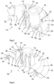
- the invention relates to a seal for sealing the end of a cylindrical component section of a component, wherein the component is designed to pass through one or more lines, with a cylindrical base body which has one or more sealing grommets for sealing the base body with respect to the line(s) guided through the component.
- Such seals are known in the prior art and are often arranged in the end region of a component that is usually arranged or mountable on the building side.
- a seal is created between the component, which can in particular be designed as a pipe penetration or as a skin seal, and one or more lines extending through the component.
- a line is understood to include both electrical lines and media-carrying lines, such as gas or water lines. The lines are guided, for example, through an opening in a roof, wall or ceiling area of a building or are laid through the ground to an installation site using the component arranged or pre-assembled on the building side.
- the object of the present invention was to provide a seal for sealing the end of a component, with the aid of which a simplified assembly of the seal on the component and also a reliable sealing connection to the component as well as to the lines passing through the component is possible.
- the base body has a circumferential turn-over collar along its circumference, which is designed to be turned over from an assembly position facing away from the cylindrical component section into a sealing position facing the cylindrical component section, and to rest against the cylindrical component section in the sealing position.
- the invention pursues the approach of specifying a type of slip-on end cap by means of which a simplified end seal is achieved between the seal itself and the component to be brought into contact with it.
- the invertible collar is preferably transferred from its assembly position to the sealing position after the seal has been brought into contact with the component, in particular after the base body has been placed on the end section of the component arranged or mountable on the building site, and after the sealing grommet(s) arranged on the base body have been brought into contact with the line(s).
- the transfer of the invertible collar from the assembly position to the sealing position takes place by means of an inverting movement or a folding over of the invertible collar on the base body.
- the invertible collar is inverted or folded over from a side of the base body facing away from the cylindrical component section to a side of the base body facing the cylindrical component section of the component.
- the turn-over collar which then projects beyond the end section of the cylindrical component section on the outside, rests against the outside of the component section, preferably in a sealing manner.
- the sealing of the turn-over collar against the outside of the cylindrical component section can be carried out or supported in one possible embodiment using a cable tie or a pipe clamp.
- the turn-over collar, in the sealing position simultaneously exerts a mechanical holding force on the component due to its sealing contact with the component.
- the seal can thus be brought into the sealing position without tools and preferably holds itself automatically to the component without the need for clamping devices. This ensures easy handling without any restrictions having to be accepted when using the sealing grommet or sealing grommets.
- the turn-over collar also allows for easy locking of the seal in the end area of the component.
- the seal is suitable for use on the outside of the building or on the roof side of the building, both on flat roofs and on sloping roofs, on garage roofs, chimneys or chimney bases and is preferably used for this purpose.
- the seal is preferably designed for the passage of lines for heat exchanger systems, in particular for heat pump systems such as monoblock or split systems, and/or for solar thermal, photovoltaic, air conditioning or heating systems.
- a skin seal is understood to mean a surface seal attached to the roof, a wall or a ceiling, for example a black tray, a roof, ceiling or wall foil and the like.
- the turn-over collar has an elastically deformable sealing ring at its collar end for circumferential contact with the component section.
- the elastically deformable sealing ring at the collar end of the turn-over collar facilitates a simplified sealing interaction with the component section receiving the seal.
- the elastically deformable sealing ring on the turn-over collar expands, so that in the sealing position, i.e., when the turn-over collar is folded over the outside of the component section, the sealing ring creates a circumferential sealing effect on the outside of the component section due to the material expansion and the resulting restoring forces acting in the sealing ring.
- the sealing ring at the end of the turn-over collar provides a sealing function without the need for additional fixing parts or fastening elements.
- the sealing ring in the assembly position and thus its initial position has a smaller diameter than the component section that can be brought into sealing contact with the sealing ring, thereby ensuring that an automatic sealing effect is achieved when the turn-over collar is brought into contact with the component section.
- the invention has been described above in a first aspect with reference to the seal itself.
- the invention further relates to the use of a seal comprising a cylindrical base body having one or more sealing grommets for sealing the base body against the line(s) routed through the component, wherein the base body has a circumferential turn-over collar along its circumference, which is designed to be turned over from an assembly position facing away from the cylindrical component section into a sealing position facing the cylindrical component section, and to bear against the cylindrical component section in the sealing position.
- the seal used is preferably a seal according to one of the above-described preferred embodiments of the first aspect
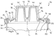
- At least two sealing grommets can have wall regions 42 which merge into one another or touch one another above or at least at the level of the sealing body 14.
- the seal 10 has, in addition to its turn-over collar 20 with the sealing ring 30 arranged at the end thereof and the sealing lip 36 arranged on the end face 26, at least one further sealing projection 48 in the receiving section, which corresponds to a section of the cylindrical component section 26 when brought into contact with the seal 10.
- the seal 10 according to the invention is fundamentally designed to be positioned in front of or at a distance from a roof, wall, or ceiling area of a building.
- the base body 14 and the components connected to the base body 14, in particular in one piece, are made of an elastically deformable material, in particular an elastomer.
- the seal 10 is manufactured using an injection molding process.
- Fig. 5 shows a possible further application of the seal 10 according to the invention, which is brought into contact with a component 12' that can be designed as a pipe duct 50, such as a corrugated pipe.
- the pipe duct 48 is, for example, concreted into an opening in a roof, wall, or ceiling area.
- the pipe duct 48 can, for example, also be laid in the ground around a building and used for the underground installation of supply lines, for example, fluid lines leading to and from a heat pump.
- the sealing lip 36 primarily comes into contact with the inner side 35 of the component 12 ⁇ and the turn-up collar 20 with its sealing ring 30 comes into contact with the outer side 32 of the component 12' designed as a pipe leadthrough 48.
Landscapes
- Engineering & Computer Science (AREA)
- Architecture (AREA)
- Civil Engineering (AREA)
- Structural Engineering (AREA)
- General Engineering & Computer Science (AREA)
- Mechanical Engineering (AREA)
- Gasket Seals (AREA)
Priority Applications (1)
| Application Number | Priority Date | Filing Date | Title |
|---|---|---|---|
| EP23220834.8A EP4579111A1 (fr) | 2023-12-29 | 2023-12-29 | Joint d'étanchéité pour l'étanchéification côté extrémité d'une partie d'un composant |
Applications Claiming Priority (1)
| Application Number | Priority Date | Filing Date | Title |
|---|---|---|---|
| EP23220834.8A EP4579111A1 (fr) | 2023-12-29 | 2023-12-29 | Joint d'étanchéité pour l'étanchéification côté extrémité d'une partie d'un composant |
Publications (1)
| Publication Number | Publication Date |
|---|---|
| EP4579111A1 true EP4579111A1 (fr) | 2025-07-02 |
Family
ID=89428656
Family Applications (1)
| Application Number | Title | Priority Date | Filing Date |
|---|---|---|---|
| EP23220834.8A Pending EP4579111A1 (fr) | 2023-12-29 | 2023-12-29 | Joint d'étanchéité pour l'étanchéification côté extrémité d'une partie d'un composant |
Country Status (1)
| Country | Link |
|---|---|
| EP (1) | EP4579111A1 (fr) |
Citations (7)
| Publication number | Priority date | Publication date | Assignee | Title |
|---|---|---|---|---|
| DE8211691U1 (de) * | 1982-04-23 | 1982-08-05 | Siemens AG, 1000 Berlin und 8000 München | Dichtungsmanschette aus elastischem Material für Wanddurchführungen |
| US20030015339A1 (en) * | 2001-07-18 | 2003-01-23 | Yazaki Corporation | Soundproof grommet for wiring harness |
| EP2103487B1 (fr) * | 2008-03-18 | 2010-08-04 | Delphi Technologies, Inc. | Manchon |
| DE102015012505B4 (de) * | 2015-09-24 | 2017-08-03 | Audi Ag | Dichtungsanordnung für eine Anschlussvorrichtung und Anschlussvorrichtung für eine Klimaanlage |
| EP3220030B1 (fr) * | 2016-03-15 | 2020-08-12 | DOYMA GmbH & Co | Élément d'étanchéité d'une conduite par rapport à une ouverture |
| US20200353881A1 (en) * | 2019-05-09 | 2020-11-12 | Yazaki Corporation | Grommet and wire harness |
| EP4148310B1 (fr) * | 2021-09-10 | 2023-08-02 | Leoni Wiring Systems France | Entretoise |
-
2023
- 2023-12-29 EP EP23220834.8A patent/EP4579111A1/fr active Pending
Patent Citations (8)
| Publication number | Priority date | Publication date | Assignee | Title |
|---|---|---|---|---|
| DE8211691U1 (de) * | 1982-04-23 | 1982-08-05 | Siemens AG, 1000 Berlin und 8000 München | Dichtungsmanschette aus elastischem Material für Wanddurchführungen |
| US20030015339A1 (en) * | 2001-07-18 | 2003-01-23 | Yazaki Corporation | Soundproof grommet for wiring harness |
| EP2103487B1 (fr) * | 2008-03-18 | 2010-08-04 | Delphi Technologies, Inc. | Manchon |
| US8042225B2 (en) * | 2008-03-18 | 2011-10-25 | Delphi Technologies, Inc. | Grommet |
| DE102015012505B4 (de) * | 2015-09-24 | 2017-08-03 | Audi Ag | Dichtungsanordnung für eine Anschlussvorrichtung und Anschlussvorrichtung für eine Klimaanlage |
| EP3220030B1 (fr) * | 2016-03-15 | 2020-08-12 | DOYMA GmbH & Co | Élément d'étanchéité d'une conduite par rapport à une ouverture |
| US20200353881A1 (en) * | 2019-05-09 | 2020-11-12 | Yazaki Corporation | Grommet and wire harness |
| EP4148310B1 (fr) * | 2021-09-10 | 2023-08-02 | Leoni Wiring Systems France | Entretoise |
Similar Documents
| Publication | Publication Date | Title |
|---|---|---|
| EP0913534A1 (fr) | Regard pour des canalisations de fluide et section de regard correspondant | |
| DE2726959A1 (de) | Dichteinsatz zum dichten verbinden von zwei rohren | |
| EP4562333B1 (fr) | Connecteur enfichable pour raccorder des conduits pour milieux liquides ou gazeux | |
| DE4331194C1 (de) | Doppelwandiges Rohrleitungssystem | |
| DE102017119704B4 (de) | Leitungskupplung und Behälter hiermit | |
| EP1703191A2 (fr) | Raccord de conduits | |
| DE3104518C2 (de) | Anschlußarmatur für flexible Wellschläuche | |
| EP4579111A1 (fr) | Joint d'étanchéité pour l'étanchéification côté extrémité d'une partie d'un composant | |
| DE3235624C2 (de) | Manschettenförmige Rohrleitungskupplung | |
| EP3557108B9 (fr) | Dispositif de raccordement pour conduites de fluide | |
| DE102005045482B4 (de) | Rohreinheit mit wenigstens zwei in einem Verbindungsbereich aneinander gefügten Leitungsrohren | |
| DE9217131U1 (de) | Armatur für einen Schlauch oder ein flexibles Rohr mit einer profilierten Außenfläche | |
| EP0503258B1 (fr) | Dispositif de connexion d'un conduit de tuyaux | |
| EP0205823A2 (fr) | Raccord à action rapide pour tuyaux ou similaires | |
| DE10307921B3 (de) | Steckverbindungseinrichtung | |
| EP2650576B1 (fr) | Raccord double pour la pose étanche de pièces longilignes | |
| DE202009014250U1 (de) | Steckkupplung zum Verbinden von insbesondere Kunststoff-Rohren | |
| WO2010145632A2 (fr) | Système de raccordement par enfichage et dispositif de fixation | |
| DE102021006393A1 (de) | Hausdurchführung zum Durchführen wenigstens einer Leitung durch eine Bodenplatte und Bodenplatte mit selbiger | |
| DE4315958C2 (de) | Rohrverbindung zwischen zwei konzentrisch übereinandergreifenden Rohrelementen | |
| EP0090934A2 (fr) | Garniture de tuyau | |
| EP3130791B1 (fr) | Composant pour un circuit d'admission d'un moteur a combustion interne | |
| EP3584487A1 (fr) | Bride tubulaire pour tuyaux d'air de combustion ainsi que système de gaz d'échappement | |
| DE19509579C2 (de) | Rohrelement zum Erstellen von Schornsteinen sowie von Abgas- und Abdampfleitungen | |
| EP0893866B1 (fr) | Dispositif d'installation d'un boítier encastrable |
Legal Events
| Date | Code | Title | Description |
|---|---|---|---|
| PUAI | Public reference made under article 153(3) epc to a published international application that has entered the european phase |
Free format text: ORIGINAL CODE: 0009012 |
|
| STAA | Information on the status of an ep patent application or granted ep patent |
Free format text: STATUS: THE APPLICATION HAS BEEN PUBLISHED |
|
| AK | Designated contracting states |
Kind code of ref document: A1 Designated state(s): AL AT BE BG CH CY CZ DE DK EE ES FI FR GB GR HR HU IE IS IT LI LT LU LV MC ME MK MT NL NO PL PT RO RS SE SI SK SM TR |
|
| STAA | Information on the status of an ep patent application or granted ep patent |
Free format text: STATUS: REQUEST FOR EXAMINATION WAS MADE |
|
| 17P | Request for examination filed |
Effective date: 20260102 |