EP3220397B1 - Aimant massif supraconducteur à base d'oxyde - Google Patents
Aimant massif supraconducteur à base d'oxyde Download PDFInfo
- Publication number
- EP3220397B1 EP3220397B1 EP15858130.6A EP15858130A EP3220397B1 EP 3220397 B1 EP3220397 B1 EP 3220397B1 EP 15858130 A EP15858130 A EP 15858130A EP 3220397 B1 EP3220397 B1 EP 3220397B1
- Authority
- EP
- European Patent Office
- Prior art keywords
- assembly
- reinforcing member
- superconducting bulk
- oxide superconducting
- bulk material
- Prior art date
- Legal status (The legal status is an assumption and is not a legal conclusion. Google has not performed a legal analysis and makes no representation as to the accuracy of the status listed.)
- Active
Links
Images


Classifications
-
- H—ELECTRICITY
- H01—ELECTRIC ELEMENTS
- H01F—MAGNETS; INDUCTANCES; TRANSFORMERS; SELECTION OF MATERIALS FOR THEIR MAGNETIC PROPERTIES
- H01F6/00—Superconducting magnets; Superconducting coils
-
- C—CHEMISTRY; METALLURGY
- C01—INORGANIC CHEMISTRY
- C01G—COMPOUNDS CONTAINING METALS NOT COVERED BY SUBCLASSES C01D OR C01F
- C01G1/00—Methods of preparing compounds of metals not covered by subclasses C01B, C01C, C01D, or C01F, in general
-
- C—CHEMISTRY; METALLURGY
- C01—INORGANIC CHEMISTRY
- C01G—COMPOUNDS CONTAINING METALS NOT COVERED BY SUBCLASSES C01D OR C01F
- C01G3/00—Compounds of copper
-
- C—CHEMISTRY; METALLURGY
- C04—CEMENTS; CONCRETE; ARTIFICIAL STONE; CERAMICS; REFRACTORIES
- C04B—LIME, MAGNESIA; SLAG; CEMENTS; COMPOSITIONS THEREOF, e.g. MORTARS, CONCRETE OR LIKE BUILDING MATERIALS; ARTIFICIAL STONE; CERAMICS; REFRACTORIES; TREATMENT OF NATURAL STONE
- C04B35/00—Shaped ceramic products characterised by their composition; Ceramics compositions; Processing powders of inorganic compounds preparatory to the manufacturing of ceramic products
- C04B35/01—Shaped ceramic products characterised by their composition; Ceramics compositions; Processing powders of inorganic compounds preparatory to the manufacturing of ceramic products based on oxide ceramics
- C04B35/45—Shaped ceramic products characterised by their composition; Ceramics compositions; Processing powders of inorganic compounds preparatory to the manufacturing of ceramic products based on oxide ceramics based on copper oxide or solid solutions thereof with other oxides
- C04B35/4504—Shaped ceramic products characterised by their composition; Ceramics compositions; Processing powders of inorganic compounds preparatory to the manufacturing of ceramic products based on oxide ceramics based on copper oxide or solid solutions thereof with other oxides containing rare earth oxides
-
- H—ELECTRICITY
- H01—ELECTRIC ELEMENTS
- H01B—CABLES; CONDUCTORS; INSULATORS; SELECTION OF MATERIALS FOR THEIR CONDUCTIVE, INSULATING OR DIELECTRIC PROPERTIES
- H01B12/00—Superconductive or hyperconductive conductors, cables, or transmission lines
- H01B12/02—Superconductive or hyperconductive conductors, cables, or transmission lines characterised by their form
-
- H—ELECTRICITY
- H01—ELECTRIC ELEMENTS
- H01F—MAGNETS; INDUCTANCES; TRANSFORMERS; SELECTION OF MATERIALS FOR THEIR MAGNETIC PROPERTIES
- H01F1/00—Magnets or magnetic bodies characterised by the magnetic materials therefor; Selection of materials for their magnetic properties
- H01F1/01—Magnets or magnetic bodies characterised by the magnetic materials therefor; Selection of materials for their magnetic properties of inorganic materials
- H01F1/03—Magnets or magnetic bodies characterised by the magnetic materials therefor; Selection of materials for their magnetic properties of inorganic materials characterised by their coercivity
- H01F1/032—Magnets or magnetic bodies characterised by the magnetic materials therefor; Selection of materials for their magnetic properties of inorganic materials characterised by their coercivity of hard-magnetic materials
- H01F1/10—Magnets or magnetic bodies characterised by the magnetic materials therefor; Selection of materials for their magnetic properties of inorganic materials characterised by their coercivity of hard-magnetic materials non-metallic substances, e.g. ferrites, e.g. [(Ba,Sr)O(Fe2O3)6] ferrites with hexagonal structure
- H01F1/11—Magnets or magnetic bodies characterised by the magnetic materials therefor; Selection of materials for their magnetic properties of inorganic materials characterised by their coercivity of hard-magnetic materials non-metallic substances, e.g. ferrites, e.g. [(Ba,Sr)O(Fe2O3)6] ferrites with hexagonal structure in the form of particles
-
- C—CHEMISTRY; METALLURGY
- C04—CEMENTS; CONCRETE; ARTIFICIAL STONE; CERAMICS; REFRACTORIES
- C04B—LIME, MAGNESIA; SLAG; CEMENTS; COMPOSITIONS THEREOF, e.g. MORTARS, CONCRETE OR LIKE BUILDING MATERIALS; ARTIFICIAL STONE; CERAMICS; REFRACTORIES; TREATMENT OF NATURAL STONE
- C04B2235/00—Aspects relating to ceramic starting mixtures or sintered ceramic products
- C04B2235/02—Composition of constituents of the starting material or of secondary phases of the final product
- C04B2235/30—Constituents and secondary phases not being of a fibrous nature
- C04B2235/32—Metal oxides, mixed metal oxides, or oxide-forming salts thereof, e.g. carbonates, nitrates, (oxy)hydroxides, chlorides
- C04B2235/3224—Rare earth oxide or oxide forming salts thereof, e.g. scandium oxide
-
- Y—GENERAL TAGGING OF NEW TECHNOLOGICAL DEVELOPMENTS; GENERAL TAGGING OF CROSS-SECTIONAL TECHNOLOGIES SPANNING OVER SEVERAL SECTIONS OF THE IPC; TECHNICAL SUBJECTS COVERED BY FORMER USPC CROSS-REFERENCE ART COLLECTIONS [XRACs] AND DIGESTS
- Y02—TECHNOLOGIES OR APPLICATIONS FOR MITIGATION OR ADAPTATION AGAINST CLIMATE CHANGE
- Y02E—REDUCTION OF GREENHOUSE GAS [GHG] EMISSIONS, RELATED TO ENERGY GENERATION, TRANSMISSION OR DISTRIBUTION
- Y02E40/00—Technologies for an efficient electrical power generation, transmission or distribution
- Y02E40/60—Superconducting electric elements or equipment; Power systems integrating superconducting elements or equipment
Definitions
- the present invention relates to an oxide superconducting bulk magnet.
- it relates to an oxide superconducting bulk magnet having a structure comprising a plurality of oxide superconducting bulk materials which are arranged in parallel.
- An oxide superconducting material comprising a single-crystal formed REBa 2 Cu 3 O 7-x (RE means rare earth element) phase in which a RE 2 BaCuO 5 phase is dispersed has a high critical current density (below, also indicated as "J c "), so is magnetized by cooling in a magnetic field or by pulse magnetization and can be used as a superconducting bulk magnet able to generate a strong magnetic field.
- RE rare earth element
- a superconducting bulk magnet has the excellent feature of being able to generate an extremely powerful magnetic field in a compact space, but since an extremely strong magnetic field is sealed in the compact space, a large electromagnetic stress acts inside an oxide superconducting bulk material. This electromagnetic stress acts so that the sealed-in magnetic field spreads, so is also called "hoop stress". In the case of a 5 to 10T class strong magnetic field, the electromagnetic stress which acts sometimes exceeds the mechanical strength of the material of the superconducting bulk material itself. As a result, the oxide superconducting bulk material is liable to break. If the oxide superconducting bulk material breaks, the superconducting bulk material can no longer generate a strong magnetic field.
- the features of a superconducting bulk magnet of compactness and a strong magnetic field can be expected to be made use of for help in improving the performance of the equipment and reducing the size and lightening the weight of equipment in applications utilizing magnets such as marine motors or windpower generators or magnetic separation.
- PLT 1 proposes a superconducting bulk magnet configured by circular columnar shaped oxide superconducting bulk material and a metal ring surrounding the same. By configuring the magnet in this way, at the time of cooling, a compressive stress due to the metal ring is applied to the oxide superconducting bulk material. This compressive stress has the effect of reducing the electromagnetic stress, so it is possible to suppress breakage of the oxide superconducting bulk material.
- PLT 2 discloses a superconducting bulk magnet reinforcing the entire side surface of the superconducting bulk material by a metal ring etc. and, furthermore, reinforcing the top and bottom surfaces of the superconducting bulk material as well by reinforcing members.
- a single-crystal formed oxide superconducting material is small in size. It is difficult to apply a superconducting bulk material obtained by working this to systems requiring generation of magnetic fields over relatively large areas (for example, large size rotating equipment, large size magnets, etc.). Therefore, it is necessary to assemble a plurality of superconducting bulk materials to form a single assembly of superconducting bulk materials and generate a magnetic field over a relatively large area.
- the above PLTs 1 and 2 only show that it is possible to prevent breakage of a single circular columnar shaped oxide superconducting bulk material and does not disclose a configuration comprising a plurality of superconducting bulk materials combined.
- FIG. 3 of PLT 3 discloses a superconducting magnetic field generating device which is manufactured by combining seven hexagonal shaped superconducting bulk materials, arranging a reinforcing member comprising a fiber reinforced resin etc. around them, and further arranging a support member comprising stainless steel, aluminum or other metal at outer circumference thereof.
- PLT 4 discloses an oxide superconducting bulk magnet comprising a superconducting bulk magnet having a through path and the circumference of the superconducting bulk magnet is covered by a high strength material.
- a superconducting bulk magnet comprising a plurality of bulk high temperature superconducting members having rectangular outer circumferences and inner circumferences which are respectively covered by rectangular high strength materials for supporting the outer circumferences.
- PLT 5 discloses a superconducting magnetic device comprising a plurality of high temperature superconducting member cells bonded together by a binder to form a single compact superconducting cell assembly in which insulators or high electrical resistance materials (stainless steel, copper, or nickel) are interposed between adjoining high temperature superconducting cells.
- PLT 5 discloses a superconducting magnet device comprising rectangular shaped high temperature oxide superconducting bulk materials having the outer circumferences of which reinforcing members are covered or coated (PLT 5, Specification, paragraph 0009 and FIG. 6 ).
- PLT 6 disclose s a superconducting permanent magnetic device having magnetic poles comprising a plurality of superconducting bulk materials arranged in parallel.
- PLT 7 provides a superconducting permanent magnet apparatus comprising a composite bulk composed of a plurality of bulk superconductors that are held in a vacuum vessel in a thermally insulated condition.
- PLT 8 discloses providing a reinforcement around a main body composed of combined superconducting bulk to improve the mechanical strength and to avoid breaking.
- the present invention was made in consideration of the above problem and has as its object to provide a superconducting bulk magnet comprising a plurality of oxide superconducting bulk materials combined together to secure the required magnetic field region, in which oxide superconducting bulk magnet, breakage of the superconducting bulk materials can be prevented even under high magnetic field strength conditions and a sufficient total amount of magnetic flux can be obtained.
- the present inventors discovered that by fitting metal reinforcing frames over the individual oxide superconducting bulk materials, then combining a plurality of members, arranging a reinforcing frame at the outer circumference of the side surfaces of the assembly of the combined member, and, furthermore, fastening the top and bottom surfaces of this assembly of the combined member by reinforcing members, it is possible to prevent breakage of the superconducting bulk materials even in a strong magnetic field.
- the present invention will be summarized below:
- a superconducting bulk magnet comprising a plurality of superconducting bulk materials combined together, wherein breakage of the superconducting bulk materials can be prevented and a strong magnetic field can be generated.
- rotary equipment which has a uniform distribution of magnetic field in the magnetic electrode with respect to the rotational direction and rotates more smoothly.
- an oxide superconducting bulk magnet according to the present embodiment (hereinafter, simply referred to as a "superconducting bulk magnet”) will be explained.
- the oxide superconducting bulk material used in the oxide superconducting bulk magnet according to the present embodiment is preferably a bulk material (so-called QMG ® material) having a structure comprising a single-crystal formed REBa 2 Cu 3 O 7-x in which a nonsuperconducting phase such as an RE 2 BaCuO 5 phase (211 phase) etc. is finely dispersed.
- QMG ® material a bulk material having a structure comprising a single-crystal formed REBa 2 Cu 3 O 7-x in which a nonsuperconducting phase such as an RE 2 BaCuO 5 phase (211 phase) etc. is finely dispersed.
- the "single-crystal form” does not have to be a complete single crystal and includes having defects not obstructing practical use such as small angle grain boundaries.
- the RE in the PEBa 2 Cu 3 O 7-x phase (123 phase) and RE 2 BaCuO 5 phase (211 phase) is a rare earth element comprising Y, La, Nd, Sm, Eu, Gd, Dy, Ho, Er, Tm, Yb, or Lu and combinations of the same.
- the 123 phase including La, Nd, Sm, Eu, and Gd is outside the 1:2:3 stoichiometric composition.
- Ba is partially substituted at the site of RE.
- La and Nd differ somewhat from Y, Sm, Eu, Gd, Dy, Ho, Er, Tm, Yb, and Lu. It is known that the ratio of the metal elements is a nonstoichiometric composition or the crystal structure differs.
- the 123 phase is formed by a peritectic reaction between the 211 phase and the liquid phase of the composite oxide of Ba and Cu, that is 211 phase+liquid phase (composite oxide of Ba and Cu) ⁇ 123 phase. Further, due to this peritectic reaction, the temperature at which the 123 phase can be formed (Tf: 123 phase generating temperature) is substantially related to the ion radius of the RE element. Along with the decrease of the ion radius, the Tf also falls. Further, Tf tends to fall along with a low oxygen atmosphere and Ag addition.
- a material comprising the single-crystal formed 123 phase in which the 211 phase is finely dispersed is formed since when the 123 phase grows as a crystal, the unreacted 211 grains are left in the 123 phase. That is, the above bulk material is formed by a reaction shown by 211 phase+liquid phase (composite oxide of Ba and Cu) ⁇ 123 phase+211 phase.
- Fine dispersion of the 211 phase in the bulk material is extremely important from the viewpoint of improvement of the critical current density J c .
- a fine amount of at least one of Pt, Rh, or Ce grain growth of the 211 phase in the semimolten state (state comprising 211 phase and liquid phase) is suppressed and as a result the 211 phase in the material is refined to about 1 ⁇ m or so.
- the amount of addition from the viewpoint of the amount at which the effect of refinement appears and the cost of the material, is preferably Pt: 0.2 to 2.0 mass%, Rh: 0.01 to 0.5 mass%, and Ce: 0.5 to 2.0 mass%.
- the added Pt, Rh, and Ce form partial solid solutions in the 123 phase.
- the elements which are not able to form solid solutions form composite oxides with the Ba or Cu and remain scattered in the material.
- each bulk oxide superconducting member forming the magnet has to have a high critical current density (J c ) even in a magnetic field. To satisfy this condition, it has to be a single-crystal formed 123 phase not containing high angle grain boundaries which become weak bonds superconductively. To obtain a further higher J c characteristic, pinning centers for stopping movement of the magnetic flux become necessary. What function as such pinning centers are the finely dispersed 211 phase. Finer dispersion of a large amount is preferable. As explained above, Pt, Rh, and Ce act to promote refinement of this 211 phase.
- the 211 phase and other nonsuperconducting phases finely disperse in the easily cleavable 123 phase and thereby play the important role of mechanically strengthening the superconductor material to nake the superconductor material viable as a bulk material.
- the ratio of the 211 phase in the 123 phase is preferably 5 to 35 vol% from the viewpoint of the J c characteristic and mechanical strength. Further, the material generally contains voids (air bubbles) of 50 to 500 ⁇ m or so in a range of 5 to 20 vol%. Furthermore, when adding Ag, depending on the amount of addition, Ag or an Ag compound of 1 to 500 ⁇ m or so is contained in a range of over 0 vol% to 25 vol%.
- the oxygen deficiency (x) of the material after crystal growth shows the temperature change of the semiconductor-like resistance at 0.5 or so.
- oxygen deficiency (x) becomes 0.2 or less, and a good superconducting characteristic is shown.
- a twin structure can be formed in the superconducting phase.
- it will be called a single-crystal form.
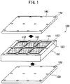
- FIG. 1 is a schematic disassembled perspective view showing one example of a superconducting bulk magnet.
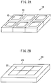
- FIGS. 2A and 2B will be used to explain examples of the configurations of conventional superconducting bulk magnets.
- FIG. 2A and FIG. 2B are both schematic perspective views showing examples of conventional oxide superconducting bulk magnets.
- the individual rectangular shaped superconducting bulk materials 12 are respectively surrounded by thick metal reinforcing materials 14.
- the superconducting bulk materials 12 are arranged discretely and the effect of integrally joining the plurality of superconducting bulk materials 12 is small.
- the superconducting bulk magnet 20 shown in FIG. 2B a plurality of superconducting bulk materials 22 are arranged closely.
- the outer circumference of the assembly is surrounded by a thick metal reinforcing material 24.
- the present inventors investigated in depth the causes of the breakage and as a result discovered that when using a plurality of superconducting bulk materials to form a superconducting bulk magnet, during the process of magnetization, an extremely large repulsive force acts between the individual superconducting bulk materials. Further, it was also learned that since there are variations in shape and performance between the individual oxide superconducting bulk materials, variations also occur in the local generation of stress. Due to the repulsive force, slight clearances are sometimes formed between the individual superconducting bulk materials. Due to such variations, the clearances are not formed uniformly. At some superconducting bulk materials, locally excessive stress acts. As a result, as shown in FIG. 2B , when forming a superconducting bulk magnet by a plurality of oxide superconducting bulk materials, it was learned that some of the superconducting bulk materials forming the assembly break.
- the thicknesses of the reinforcing frames provided at the side surfaces of the superconducting bulk materials are 5.0 mm or less, more preferably 3.0 mm or less, still more preferably 1.0 mm or less.
- the superconducting bulk magnet according to the present embodiment has bulk material reinforcing members at the side surfaces of the individual superconducting bulk materials, has an assembly side surface reinforcing member at the side surfaces of the assembly of the superconducting bulk materials, and furthermore has reinforcing members covering the entire top surface and bottom surface of the assembly of the superconducting bulk materials. That is, as shown in FIG.
- the superconducting bulk magnet according to the present embodiment 100 has a structure wherein bulk material reinforcing members 120 is fit over the side surfaces of the individual superconducting bulk materials 110 which are arranged to form an assembly, wherein an assembly side surface reinforcing member 130 is arranged at the side surfaces of the assembly, wherein an assembly top reinforcing member 140 and assembly bottom reinforcing member 150 are placed at the top surface and bottom surface of the assembly, and wherein the above-mentioned reinforcing members are fastened at a plurality of locations at the circumferences by fastening members (not shown), and thereby the assembly side surface reinforcing member 130, assembly top reinforcing member 140 and assembly bottom reinforcing member 150 are fastened to form an integral unit.
- FIG. 1 the case where there are six superconducting bulk materials 110 fit into bulk material reinforcing members 120 (below, these together referred to as “bulk material units”) is shown, but the present invention is not limited to this example. For example, the action and effect of the present invention are similar even with five or seven bulk material units etc.
- the bulk material reinforcing members 120 are hollow members fitting with the side shapes of the superconducting bulk materials 110 and are provided at the side surfaces of the superconducting bulk materials 110.
- the difference in the coefficient of thermal expansion of the bulk material reinforcing members 120 and the coefficient of thermal expansion of the superconducting bulk materials 110 is utilized so that at the time of cooling, the bulk material reinforcing members 120 press against and reinforce the side surfaces of the oxide superconducting bulk materials 110 to thereby counter the hoop stresses of the individual oxide superconducting bulk materials 110 and suppress breakage as an effect. Further, even if the superconducting bulk materials 110 are provided with the bulk material reinforcing members 120, the top surface and bottom surface are exposed from the bulk material reinforcing members 120.
- the bulk material reinforcing members are preferably thick.
- the bulk material reinforcing members are preferably thin.
- the bulk material reinforcing members 120 as explained above are preferably made a thickness of 5.0 mm or less, more preferably 3.0 mm or less, still more preferably 1.0 mm or less, so as to hold the magnetic field strength or total amount of magnetic flux per unit area demanded from the superconducting bulk magnet 100.
- the material of the bulk material reinforcing members 120 one having sufficient strength such as stainless steel, titanium alloy, copper alloy, aluminum alloy, etc. is preferable.
- the lower limit value of the thickness of the bulk material reinforcing members 120 is determined in accordance with the strengths of these materials.
- the bulk material reinforcing members can be prepared by a lathe, machining center, electrodischarge machine, or other ordinary metal working machine. Furthermore, the oxide superconducting bulk materials and the bulk material reinforcing members can be joined by a resin, joined by solder, joined by grease, etc. Further, the bulk material reinforcing members can ease the excessive stress which, as explained above, locally acts on part of the oxide superconducting bulk materials due to non-uniform formation of clearances between them, thus leading to the effect of preventing breakage of the bulk materials.
- the superconducting bulk materials broke. This is believed to be because, as explained above, limited unevenness in the outside shapes of the superconducting bulk materials is unavoidable in working the superconducting bulk materials, positions where the stress concentrates are formed between adjoining superconducting bulk materials, and therefore breakage of the non-elastic superconducting bulk materials is caused. Therefore, it is guessed that the bulk material reinforcing members provided at the side surfaces of the superconducting bulk materials act to ease such stress.
- a plurality of bulk material units are arranged and an assembly formed.
- the top surfaces of the superconducting bulk materials 110 are aligned in the same direction and the bulk material reinforcing members 120 of the adjoining superconducting bulk materials 110 are brought into contact to form the assembly.
- FIG. 1 it is also possible to arrange six superconducting bulk materials 110 provided with bulk material reinforcing members 120 in a 2 ⁇ 3 array to form an assembly.
- the assembly is constrained by the side surfaces of the assembly contacting the inner circumferential surfaces of the assembly side surface reinforcing member 130 corresponding to the shapes of the side surfaces.
- the assembly side surface reinforcing member 130 is formed to a thickness greater than the bulk material reinforcing members. For example, it is a thickness of 5 mm or more suitably selected considering the size of the superconducting bulk magnet as a whole, etc. Furthermore, connecting the assembly side surface reinforcing member 130 with both the assembly top reinforcing member 140 and assembly bottom reinforcing member 150 is necessary for securing the strength. In particular, this is necessary for dealing with the bending or twisting stress. However, there is no need for connection over the entire circumference of the side surfaces.
- the ratio of the part connected in the circumferential direction may be 50% or more, preferably 70% or more, more preferably 90% or more, further preferably 100%.
- the height of the parts of the assembly side surface reinforcing member 130 contacting the side surfaces of the assembly has to be at least the height of the assembly, that is, the height of the bulk units.
- the height of the part of the assembly side surface reinforcing member 130 contacting the side surfaces of the assembly is preferably substantially the same as the height of the assembly, that is, the height of the bulk units. Further, the height of the assembly side surface reinforcing member 130 may also be higher than the height of the bulk units.
- a clearance forms between the top surfaces of the bulk material units and the bottom surface of the assembly top reinforcing member 140 or between the bottom surfaces of the bulk material units and the top surface of the assembly bottom reinforcing member 140, but this clearance may be filled with solder, resin, grease, etc.
- all of these clearances are preferably 10 mm or less, more preferably 1 mm or less.
- the bulk units may be exposed by openings at parts of the assembly side surface reinforcing member as well.
- the assembly side surface reinforcing member and assembly top reinforcing member are integrally joined, but the assembly bottom reinforcing member is not integrally joined. Further, almost all of the side surfaces of the assembly are exposed. They are not covered by the assembly side surface reinforcing member.
- the side surfaces of the assembly are covered by the assembly side surface reinforcing member, the top surface and bottom surface of the assembly are respectively covered by the assembly top reinforcing member and assembly bottom reinforcing member, and the assembly side surface reinforcing member, assembly top reinforcing member, and assembly bottom reinforcing member are joined into an integral unit.
- the function of preventing breakage due not to hoop stress generated at the individual oxide superconducting bulk materials, but hoop stress-like electromagnetic stress generated in the oxide superconducting bulk magnet as a whole as an assembly of the oxide superconducting bulk materials is handled by the thick assembly side surface reinforcing member surrounding the assembly of the plurality of oxide superconducting bulk materials.
- the material of the assembly side surface reinforcing member 130 is not particularly limited. For example, it may be the same material as the bulk material reinforcing members 120 or may be a different one. Specifically, the sufficiently strong stainless steel, titanium alloy, copper alloy, or aluminum alloy is preferable.
- the assembly reinforcing members can be prepared by a lathe, machining center, electrodischarge machine, or other ordinary metal working machine. Furthermore, these members and bulk material units can for example be joined by a resin, joined by solder, joined by grease, etc. Further, to bury the clearances between these members and bulk material units, it is effective to fill the clearances with a resin, solder, grease, etc.
- the assembly top reinforcing member 140 and assembly bottom reinforcing member 150 are fastened to the top surface and bottom surface of the assembly.
- the assembly top reinforcing member 140 and assembly bottom reinforcing member 150 are fastened to be integrally joined with the assembly side surface reinforcing member so as to prevent the stress from being released from positions where stress locally concentrated at the assembly.
- the thicknesses of the assembly top surface reinforcing member and assembly bottom surface reinforcing member are preferably 2 mm or more or thicker than the thickness of the bulk material reinforcing members.
- the fastening means is not particularly limited.
- bolts or other fastening members may be used or soldering or other bonding means may be used.
- a container comprising the assembly side surface reinforcing member and assembly top reinforcing member joined into an integral unit over the oxide superconducting bulk materials arranged on the assembly bottom reinforcing member and then fasten the container and assembly bottom reinforcing member.
- the above-mentioned fastening means may be used.
- bolts or other fastening members are used for fastening the assembly side surface reinforcing member and the top and bottom surface reinforcing members together.
- the top surfaces and bottom surfaces of the assembly side surface reinforcing member 130 and the assembly top reinforcing member 140 and assembly bottom reinforcing member 150 are formed with pluralities of fastening holes 132, 142, and 152 at positions where the bolts are to be inserted.
- the bolt diameters, bolting intervals, intervals between bolts, etc. are design matters and may be suitably designed so that sufficient strength is obtained corresponding to the shape or size of the oxide superconducting bulk magnet 100.
- the fastening holes 132 are formed at each of the top surface and bottom surface of the assembly side surface reinforcing member 130 at the four corners and positions where the adjoining superconducting bulk materials 110 contact, for a total of 10 locations.
- the fastening holes 142, 152 are formed as through holes at positions corresponding to the fastening holes 132 of the top surface and bottom surface of the assembly side surface reinforcing member 130. Note that, in FIG. 1 , two through holes are also formed other than at the outer circumferences of the assembly top reinforcing member 140 and assembly bottom reinforcing member 150, but the example utilizing these through holes will be explained later.
- the superconducting bulk magnet according to the present embodiment 100 is configured to reinforce by an assembly side surface reinforcing member 130 an assembly formed by arrangement of a plurality of bulk material units contacting each other and to cover the top surface and bottom surface of the assembly by an assembly top reinforcing member 140 and assembly bottom reinforcing member 150 and fasten them to the assembly side surface reinforcing member 130 to form an integral unit.
- the bulk material reinforcing members 120 and assembly side surface reinforcing member 130 can prevent excessive force from locally acting on part of the superconducting bulk materials 110 forming the assembly. As a result, it is possible to prevent breakage of all superconducting bulk materials 110 forming the superconducting bulk magnet.
- the assembly top reinforcing member and assembly bottom reinforcing member are not necessarily configured symmetrically at the top and bottom.
- the situation may be illustrated of cooling the bulk magnet from the assembly bottom reinforcing member side, generating a magnetic field, and making the space for active use of the generated magnetic field at the side of the assembly top reinforcing member.
- the assembly bottom reinforcing member is made from an oxygen-free copper plate with good thermal conductivity etc. while the assembly top surface reinforcing member is made a nonmagnetic material not obstructing the magnetic field such as a stainless steel plate.
- oxygen-free copper and stainless steel differ in coefficient of thermal expansion and mechanical strength as well, in addition to a force pushing the bulk material reinforcing members apart outward, a force trying to bend the oxide superconducting bulk magnet as a whole or a force trying to twist it acts.
- the superconducting bulk magnet according to the present embodiment stresses application to the magnetic pole of a generator, motor, or other rotary equipment. In such rotary equipment, it is necessary to put the magnetic flux generated by the oxide superconducting bulk magnet attached to the rotor efficiently across the windings of the stator positioned at the outside of the rotor (assembly top surface reinforcing plate side).
- the assembly bottom reinforcing member forming the surface attached to the rotor should be made of a material with a good thermal conductivity.
- the material of the assembly top reinforcing member differs from the material of the assembly bottom reinforcing member.
- the assembly bottom reinforcing member is preferably configured from a material with a thermal conductivity of 50W/m ⁇ K or more. Specifically, copper, copper alloy, aluminum, or an aluminum alloy is preferable.
- the assembly top reinforcing member is required to be higher in strength than the assembly bottom reinforcing member.
- the yield strength at room temperature (300K) is preferably 200 MPa or more.
- stainless steel, a titanium alloy, copper alloy, aluminum alloy, etc. may be illustrated.
- the assembly top reinforcing member and assembly bottom reinforcing member can be fabricated by a lathe, machining center, electrodischarge machine, or other usual metal working machine. Furthermore, these members and the bulk material units can for example be joined by a resin, joined by solder, joined by grease, etc. Further, to fill the clearances between these members and the bulk material units, filling a resin, solder, grease, etc. is effective.
- the present inventors thought of more reliably and effectively preventing the effects of bending or twisting force acting on the bulk magnet due to the difference in the materials of the assembly top reinforcing member and assembly bottom reinforcing member by fastening the assembly top reinforcing member and assembly bottom reinforcing member to the assembly side surface reinforcing member and further fastening the assembly top reinforcing member and assembly bottom reinforcing member not only at the flat outer circumference of the superconducting bulk magnet, but also through the inside of the assembly.
- the inventors thought of increasing the bolts and other fastening members inside the assembly.
- the assembly of the superconducting bulk materials according to the present embodiment secures a sufficient total amount of magnetic flux by a limited area by the individual superconducting bulk materials being arranged densely separated by the bulk material reinforcing members. There is no space for passing through bolts at the insides of the assembly side surface reinforcing members (inside of assembly).
- the shape of the oxide superconducting bulk materials forming the superconducting bulk magnet in the present embodiment is not particularly limited.
- the oxide superconducting bulk materials may be a polygonal shape of a triangular shape or more in a plan view.
- FIG. 5 is a plan view in the present embodiment showing an example where the superconducting bulk materials forming the superconducting bulk magnet are octagonal in plan view.
- the superconducting bulk materials 110 are columnar shaped. As shown in FIG. 5 , when viewed in a plan view, they are squares with corners chamfered to form octagonal shapes. Note that, the superconducting bulk materials 110 according to the present embodiment are square shapes with four corners chamfered to form octagonal shapes, but the superconducting bulk materials 110 used for the superconducting bulk magnet according to the present embodiment 100 may also be square shapes without chamfered corners. Note that, the stress generated due to the repulsive force easily concentrates at the four corners of the superconducting bulk materials 110. Breaks may occur from the parts where the stress concentrates. By chamfering the side surfaces of the superconducting bulk materials 110, the secondary effect can also be obtained that such causes of fracture can also be removed.
- FIG. 9 is a plan view in the present embodiment showing an example where the superconducting bulk materials forming the superconducting bulk magnet are hexagonal in shape in plan view.
- the shapes of the oxide superconducting bulk materials hexagonal columnar shapes, when arranging a plurality of oxide superconducting bulk materials to form an assembly, arrangement without clearance becomes possible. As a result, it is possible to sufficiently raise the overall magnetic field strength and total amount of magnetic flux per unit area. Further, compared with square columnar shapes, they are closer to circular columns, so the trapped magnetic field characteristics are better than the square columnar shapes.
- the oxide superconducting bulk materials may have, as shapes seen from a plan view, polygonal shapes with rounded vertices. That is, the corners of the polygonal shapes may be made of curves and may be rounded.
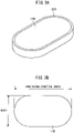
- oxide superconducting bulk materials may have racetrack shapes comprising, in a plan view, a pair of facing parallel lines and a pair of facing curved lines connected together.
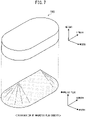
- FIG. 3A is a perspective view showing an example where the superconducting bulk materials forming the superconducting bulk magnet in the present embodiment are racetrack shaped.
- FIG. 3B is an explanatory view explaining the size of the racetrack shaped superconducting bulk material shown in FIG. 3A .
- FIG. 6 is a disassembled perspective view showing one example of an oxide superconducting bulk magnet comprising racetrack shaped superconducting bulk materials.
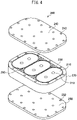
- FIG. 4 as explained above, is a disassembled perspective view showing one example of an oxide superconducting bulk magnet comprising racetrack shaped superconducting bulk materials formed with through holes.
- Each racetrack shaped oxide superconducting bulk material 110 has a top surface, bottom surface, and side surfaces.
- the side surfaces are formed into a racetrack shape comprising a pair of facing parallel lines and a pair of facing curved lines connected together.
- a racetrack shaped bulk material reinforcing member 120 is fit.
- the straight line direction when viewed from the top surface or bottom surface is defined as the "longitudinal direction" while the "longitudinal direction length" and “width” are defined as shown in FIG. 3B .
- the oxide superconducting bulk magnet 100 shown in FIG. 6 comprises an assembly formed by arranging a plurality of bulk material units in contact with each other, each of the bulk material units comprising a racetrack shaped oxide superconducting bulk material 110 and bulk material reinforcing member 120, a thick assembly side surface reinforcing member 130 surrounding the side surfaces thereof, an assembly top reinforcing member 140 and assembly bottom reinforcing member 150 covering the top surface and bottom surface of the assembly, and spacers 160 for fastening and affixing these reinforcing members.
- the magnet 200 shown in FIG. 4 as well except for through holes being formed in the oxide superconducting bulk materials 210, the magnet has a similar configuration to the oxide superconducting bulk magnet 100 shown in FIG. 6 .
- the spacers 160 and 260 described in FIG. 4 and FIG. 6 are for providing locations for fastening the assembly top reinforcing members 140, 240 and assembly bottom reinforcing members 150, 250 other than the assembly side surface reinforcing members 130, 230.
- the spacers 260 may also be arranged in the through holes 212 of the oxide superconducting bulk materials 210.
- the spacers 160, 260 are formed with holes at the top or bottom in the height direction. These holes may also be through holes which run from the top to the bottom. Due to this, the assembly top reinforcing members 140, 240 and assembly bottom reinforcing members 150, 250 can be firmly fastened by bolts or other fastening members and can effectively reinforce the oxide superconducting bulk magnets 100, 200.
- the advantage of making the shape of a single oxide superconducting bulk material a racetrack shape high uniformity of the distribution of magnetic field in the longitudinal direction may be mentioned.
- the magnetic fields at the boundary parts of the oxide superconducting bulk materials become inverse to the polarity of the magnetic field at the centers and uneven. Therefore, with the oxide superconducting bulk magnets 100,200 comprising the racetrack shaped oxide superconducting bulk materials 110, 210 shown in FIG. 6 and FIG. 4 , magnetic field distributions with high uniformities in the longitudinal direction are obtained.
- the distribution of trapped magnetic flux of a single oxide superconducting bulk material differs depending on the magnetization conditions. For example, when using a general superconducting bulk material comprising single-crystal formed RE 1 Ba 2 Cu 3 O y in which RE 2 BaCuO 5 is dispersed at the liquid nitrogen temperature (77K), the oxide superconducting bulk material is formed into a racetrack shape such as shown in FIG. 7 , the critical current density becomes relatively low. Specifically, if performing magnetization by a static magnetic field in a 5T or so sufficiently high magnetic field, the distribution of magnetic flux density becomes the distribution shown in the lower side of FIG. 7 and the superconducting current flows through the bulk material as a whole.
- a structure can be obtained which is strong against strain and stress of the oxide superconducting bulk magnet 200.
- the inside diameter of the through hole 212 may for example be made larger than the diameter of the bolt or other fastening member.
- oxide superconducting bulk materials may have circular columnar shapes.
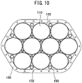
- FIG. 10 is a plan view showing an example where the superconducting bulk materials forming the superconducting bulk magnet in the present embodiment are circular shapes in a plan view.
- the bulk material reinforcing members arranged at the side surfaces of the oxide superconducting bulk materials can isotropically give high pressure to the oxide superconducting bulk materials and the effect of reduction of the hoop stress is high.
- the single-crystal formed bulk material obtained by crystal growth is a circular columnar shape, so working is easy and the loss when working the oxide superconducting bulk materials is small, so the yield is good. Furthermore, the trapped magnetic field characteristic is excellent.
- the oxide superconducting bulk magnets 100, 200 according to the present embodiment comprising the above oxide superconducting bulk materials are excellent as magnetic poles of rotary equipment such as generators or motors as explained above.
- FIG. 11 shows an example of the configuration of rotary equipment 300 having an oxide superconducting bulk magnet 100 comprising racetrack shaped oxide superconducting bulk materials 110 as a magnetic pole.
- FIG. 11 shows the state where the assembly top reinforcing member covering the top surface of the assembly of bulk material units is removed.
- the rotary equipment 300 includes a disk shaped rotor 310 rotating about a shaft 320 and provided at its outer circumferential surface with oxide superconducting bulk magnets 100 at predetermined intervals as magnetic poles.
- the oxide superconducting bulk magnets 100 are strongly connected to the outer circumferential part of the rotor 310 by bolts etc.
- the longitudinal direction of the racetrack shaped oxide superconducting bulk material 110 matches with the direction A of rotational movement of the rotor 310. That is, the longitudinal direction of the oxide superconducting bulk material 110 becomes vertical to the shaft 320.
- the stator (not shown) facing the magnetic pole intersects with the magnetic flux of the substantially constant magnetic flux density while one magnetic pole is being passed. If the rotational speed is constant, a substantially constant magnetomotive force can be generated.
- the stator experiences a plurality of peaks of magnetic flux density while passing through a single magnetic pole.
- the magnetic flux density being constant, if a generator, it is possible to suppress the high harmonic components, while if a motor, it becomes possible to suppress the cogging torque and obtain smooth rotation. Therefore, the fact that the magnetic flux density is constant is a great merit of a magnetic pole which is formed using a racetrack shaped oxide superconducting bulk material 110.
- the superconducting bulk magnet is attached to rotary equipment etc. as a magnetic pole in the state having the assembly bottom reinforcing member.
- the surface for attachment to the magnetic pole at the rotary equipment etc. is, for example, provided with a cooling plate comprising oxygen-free copper
- the superconducting bulk magnet need not have an assembly bottom reinforcing member. That is, when attaching a superconducting bulk magnet not having an assembly bottom reinforcing member to the cooling plate of the rotary equipment and fastening them together to be joined integrally, the above-mentioned configuration of the superconducting bulk magnet can be realized because the superconducting bulk magnet can include the cooling plate. Therefore, the assembly bottom reinforcing member may also be the surface of attachment to the magnetic pole of the rotary equipment etc.
- the assembly top reinforcing member may also have curvature.
- the flat surface of each oxide superconducting bulk material at the side of the assembly top reinforcing member may also be arranged to follow this curve (that is, so that the flat surface of the center oxide superconducting bulk materials at the assembly top reinforcing member side sticks out at the assembly top reinforcing member side from the flat surface of the surrounding oxide superconducting bulk materials at the assembly top reinforcing member side).
- the side surfaces of the assembly contact only parts of the assembly side surface reinforcing member. Clearances are formed between the inner circumferential surface of the assembly side surface reinforcing member and the side surfaces of the assembly.
- a Gd-Ba-Cu-O-based oxide superconducting bulk material was used.
- platinum 0.5 mass% and silver 10 mass% were added. This weighed powder was sufficiently kneaded over 1 hour, then was calcined in the atmosphere at 1173K for 8 hours.
- a mold was used to shape the calcined powder into a disk shape.
- This shaped article was heated up to 1423K to a molten state and held for 30 minutes, then was seeded in the middle of lowering the temperature. This was gradually cooled in the 1278K to 1252K temperature region over 100 hours to grow a crystal and obtain a diameter 70 mm single-crystal formed superconducting bulk material.
- the single-crystal superconducting bulk material was worked into the shape shown in FIG. 5 to obtain a side 50 mm and height 20 mm octagonal shape and was heat treated in an oxygen stream at 723K for 100 hours.
- an assembly bottom reinforcing member comprising an oxygen-free copper plate
- an assembly top reinforcing member comprising a stainless steel SUS316L plate
- a total of 10 locations were bolted to fasten the assembly side surface reinforcing member, assembly top reinforcing member, and assembly bottom reinforcing member integrally.
- two locations were bolted inside the assembly.
- Table 2 shows a comparison of Cases 1-B to 1-D in the case based on the total amount of magnetic flux of the superconducting bulk magnet of Case 1-A under magnetization conditions of an external magnetic field of 4T.
- a total amount of magnetic flux was high since it was confirmed to be 90% or more. Note that, in Table 2, the number of oxide superconducting bulk materials which broke under conditions of an external magnetic field of 5T are shown.
- Example 1 A test similar to Example 1 was performed for the case of combining two by two, that is, a total of four, superconducting bulk materials.
- Cases 2-A to 2-D of Table 3 in addition to eight locations of the assembly side surface reinforcing members at the outer circumferences of the flat surfaces of the superconducting bulk magnets, bolts were passed through single locations at the inside of the superconducting bulk magnets and fastened.
- no inside bolting was performed.
- Table 3 shows a comparison in the case based on the total amount of magnetic flux of the superconducting bulk magnet of Case 2-A for the Cases 2-B to 2-E under magnetization conditions of an external magnetic field of 4T.
- Example 3 a superconducting bulk magnet having the racetrack shaped oxide superconducting bulk materials shown in FIG. 3A was examined.
- the oxide superconducting bulk magnet of the present example Gd(Dy)-Ba-Cu-O-based oxide superconducting bulk materials were used.
- BaCeO 3 1.5 mass% and silver 20 mass% were added. This weighed powder was sufficiently kneaded over 1 hour, then calcined in the atmosphere at 1173K for 8 hours.
- This shaped article was heated to 1423K to a molten state, held for 30 minutes, then seeded in the middle of lowering the temperature. This was gradually cooled in the 1278K to 1252K temperature region over 300 hours to grow a crystal and obtain a diameter 155 mm single-crystal formed oxide superconducting bulk material.
- the prepared single-crystal formed oxide superconducting bulk material was worked into a racetrack shape (longitudinal direction length 120.0 mm, width 60.0 mm, height 20.0 mm) and was heat-treated in an oxygen stream at 723K for 100 hours.
- a stainless steel SUS316L racetrack shape bulk material reinforcing member (outer circumference longitudinal direction length 122.0 mm and width 62.0 mm, inside circumference longitudinal direction length 120.0 mm and width 60.0 mm, height 20.0 mm, and thickness 1.0 mm) was fit and fastened with resin. Furthermore, two racetrack shaped oxide superconducting bulk materials with bulk material reinforcing members were prepared in the same manner as the above-mentioned manner.
- a stainless steel SUS316L assembly top reinforcing member and assembly bottom reinforcing member having screw holes shape of outer circumference same as outer circumference of assembly side surface reinforcing member, thickness 5.0 mm
- screw holes shape of outer circumference same as outer circumference of assembly side surface reinforcing member, thickness 5.0 mm
- the oxide superconducting bulk materials, bulk material reinforcing members, and assembly side surface reinforcing member were buried in a resin (product name: STYCAST 2850FT, made by Ablestik Japan) so as not to shift during the magnetization test.
- an oxide superconducting bulk magnet with a thickness of the bulk material reinforcing members of zero that is, no bulk material reinforcing members
- an oxide superconducting bulk magnet with a thickness of the bulk material reinforcing members of 0.5 mm Example 3-B
- an oxide superconducting bulk magnet with a thickness of 1.0 mm Example 3-C
- an oxide superconducting bulk magnet with a thickness of 2.0 mm Example 3-D
- Table 4 shows a comparison in the case based on the total amount of magnetic flux of the oxide superconducting bulk magnet of Comparative Example 3-A under magnetization conditions of an external magnetic field of 5T and the presence of breakage of the oxide superconducting bulk materials at the time of external magnetic field 5T magnetization.
- Table 4 when one or more oxide superconducting bulk materials broke under conditions of an external magnetic field of 5T, "Yes" was entered in the field "Breaks".
- the thickness of the bulk material reinforcing member was 1 mm or less, the total amount of magnetic flux could be confirmed to be high since it was 90% or more.
- oxide superconducting bulk materials were magnetized by cooling in a magnetic field using a refrigerating machine at about 30K and the distribution of the magnetic field was measured. Under conditions of an external magnetic field of 4T, no breakage was seen in any of the oxide superconducting bulk magnets. Next, the external magnetic field was changed to 5T, whereupon the oxide superconducting bulk materials of the oxide superconducting bulk magnets of Examples 3-B to 3-D did not break at all, but the oxide superconducting bulk magnet of Comparative Example 3-A broke.
- an oxide superconducting bulk magnet comprising a plurality of racetrack shaped superconducting bulk materials having the structure of the present invention in which breakage of the oxide superconducting bulk material is prevented and a strong magnetic field can be generated. Further, it is shown that by making the thickness of the bulk material reinforcing member 1.0 mm or less, a high total amount of magnetic flux can be obtained.
- Example 4 an oxide superconducting bulk magnet comprising oxide superconducting bulk materials formed with through holes shown in FIG. 4 was examined.
- the oxide superconducting bulk magnet of the present example Gd(Dy)-Ba-Cu-O-based oxide superconducting bulk materials were used.
- BaCeO 3 1.5 mass% and silver 20 mass% were added. This weighed powder was sufficiently kneaded over 1 hour, then calcined in the atmosphere at 1173K for 8 hours.
- This shaped article was heated to 1423K to a molten state, held for 30 minutes, then seeded in the middle of lowering the temperature. This was gradually cooled in the 1278K to 1252K temperature region over 320 hours to grow a crystal and obtain a diameter 155 mm single-crystal formed oxide superconducting bulk material.
- the prepared single-crystal formed oxide superconducting bulk material was worked into a racetrack shape (longitudinal direction length 110.0 mm, width 70.0 mm, height 20.0 mm). Furthermore, at the center part of the oxide superconducting bulk material, two diameter 10.0 mm through holes were formed in the longitudinal direction with a center interval of 40 mm. After this, the member was heat treated in an oxygen stream at 723K for 100 hours.
- a stainless steel SUS316L racetrack shaped bulk material reinforcing member (outer circumference longitudinal direction length 112.0 mm and width 72.0 mm, inside circumference longitudinal direction length 110.0 mm and width 70.0mm, height 20.0 mm, and thickness 1.0 mm) was fit and fastened with resin. Furthermore, two racetrack shaped oxide superconducting bulk materials with bulk material reinforcing members were prepared in the same manner as the above-mentioned manner.
- the oxide superconducting bulk materials, bulk material reinforcing members, and assembly side surface reinforcing member were buried in a resin (product name: STYCAST 2850FT, made by Ablestik Japan) so as not to shift during the magnetization test.
- Example 4-A an oxide superconducting bulk magnet with bulk material reinforcing members of zero thickness (that is, with no bulk material reinforcing members)
- Example 4-C an oxide superconducting bulk magnet with bulk material reinforcing members of 1.0 mm thickness
- an assembly side surface reinforcing member at the outer circumference of the side surfaces of the assembly of the oxide superconducting bulk materials comprising a plurality of racetrack shaped bulk material units, each of which comprises a racetrack shaped oxide superconducting bulk material having a hole part and the outer circumference into which a racetrack shaped bulk material reinforcing member is fit, and fastening the assembly top reinforcing member and assembly bottom reinforcing member to the top surface and bottom surface of the assembly, the oxide superconducting bulk magnet became an excellent source of generation of a magnetic field.
- Example 5 an oxide superconducting bulk magnet configured from circular columnar shaped oxide superconducting bulk materials shown in FIG. 10 was examined.
- Gd-Ba-Cu-O-based oxide superconducting bulk materials were used.
- calcined powders were weighed to give a molar ratio of 123:211 of 3:1, then 10 mass% of silver oxide powder was added to prepare mixed powder.
- This mixed powder was shaped using an inside diameter 65 mm cylindrical shaped mold to prepare a shaped article.
- This shaped article was heated to render it a semimolten state, then was brought into contact with a seed crystal at 1313K, then was gradually cooled in a temperature region of 1278K to 1255K over 280 hours to grow a crystal and obtain a diameter approximately 51 mm single-crystal formed oxide superconducting bulk material.
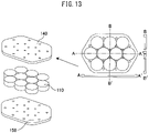
- FIG. 13 shows a cross-sectional view between A-A' and a cross-sectional view between B-B'.
- a thickness 11.0 mm oxygen-free copper plate having screw holes was used as the assembly bottom reinforcing member. These were screwed together to prepare the comparative example oxide superconducting bulk magnet (5-B).
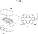
- 10 diameter 38 mm, height 12 mm oxide superconducting bulk materials were prepared by the same manner as the above-mentioned manner. Further, diameter 38 mm, height 5 mm stainless steel plates were fabricated. Therefore, as the bulk material reinforcing members, inside diameter 39.0 mm, outer diameter 50.0 mm (thickness 5.5 mm) stainless steel rings were used. As shown in FIG. 14 , inside the stainless steel rings, the stainless steel plates were placed under the oxide superconducting bulk materials and these bonded with resin. In this way, 10 bulk material units were prepared. There was no assembly side surface reinforcing member. As the assembly top reinforcing member, a thickness 9.0 mm SUS316L plate having screw holes was used.
- FIG. 14 shows a cross-sectional view between A-A' and a cross-sectional view between B-B'.
- a thickness 11.0 mm oxygen-free copper plate having screw holes was used as the assembly bottom reinforcing member. These were screwed together to prepare the comparative example oxide superconducting bulk magnet (5-C).
- the assembly top reinforcing member a thickness 4.5 mm SUS316L plate having screw holes was used, while as the assembly bottom reinforcing member, a thickness 11.0 mm oxygen-free copper plate having screw holes was used. These were screwed together to prepare the oxide superconducting bulk magnet according to this invention (5-D).
- the assembly top reinforcing member a thickness 4.5mm SUS316L plate having screw holes was used, while as the assembly bottom reinforcing member, a thickness 11.0 mm oxygen-free copper plate having screw holes was used. Furthermore, when joining the assembly top reinforcing member and the assembly bottom reinforcing member through the assembly side surface reinforcing member, spacers were placed in the spaces between the circular columnar shaped oxide superconducting bulk materials with the bulk material reinforcing members and fastening members were used to join these at these positions as well to raise the strength and prepare the example oxide superconducting bulk magnet according to this invention (5-E).
- the shapes of the outer circumferences of the assembly top reinforcing member and the assembly bottom reinforcing member were the same as the shape of the outer circumference of the assembly side surface reinforcing member of 5-A.
- the assembly top reinforcing member and the assembly bottom reinforcing member were soldered to the assembly side surface reinforcing member.
- the oxide superconducting bulk material and the assembly side surface reinforcing member were buried in resin (product name: STYCAST 2850FT, made by Ablestik Japan) to prevent them from shifting during the magnetization test.
- Table 5 shows the presence of breakage in the oxide superconducting bulk materials and the number of the broken circular columnar shaped oxide superconducting bulk materials under the magnetization conditions of various external magnetic fields. Further, the results when measuring the amount of magnetic flux on one bulk material unit at the surface of the assembly top reinforcing member at the time of magnetization under conditions of 30K and 2.5T are shown indexed to Comparative Example 5-A as 100%. Further, at the time of magnetization at 30K and 1.5T, in each case, there was no breakage of the oxide superconducting bulk materials.
- Comparative Example 5-B Under conditions of an external magnetic field of 30K and 3.0T, in Comparative Example 5-B, four oxide superconducting bulk materials broke, but in the other examples, there was no breakage. Further, under conditions of an external magnetic field of 30K and 4.0T, in Comparative Example 5-A, two oxide superconducting bulk materials broke, but in Comparative Example 5-C, Invention Example 5-D, and Invention Example 5-E, there was no breakage. Further, under conditions of an external magnetic field of 30K and 6.0T, in Example Invention 5-D, one oxide superconducting bulk material broke, but in Invention Example 5-E, there was no breakage.
- Comparative Example 5-B With magnetization of 30K and 3.0T, in Comparative Example 5-B, breakage was already seen in four bulk materials. This was because in Comparative Example 5-B, there were no bulk material reinforcing members and because only part of the side surfaces of the assembly was covered, so at the time of screwing, the compressive force due to the screwing directly acted on the oxide superconducting bulk materials.
- the oxide superconducting bulk materials are made of ceramic, so while the compressive strength is larger than the tensile strength, basically the members are single-crystalline materials, so they are easily chipped and crack with respect to outer force. The cause is believed to be that the assembly top reinforcing member can only be fastened by a force of an extent whereby the oxide superconducting bulk materials will not break.
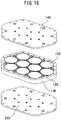
- Example 6 an oxide superconducting bulk magnet configured from hexagonal columnar shaped oxide superconducting bulk materials shown in FIG. 9 was examined.
- Dy-Ba-Cu-O-based oxide superconducting bulk materials were used.
- calcined powders were weighed to give a molar ratio of 123:211 of 3:1, then 10 mass% of silver oxide powder was added to prepare mixed powder.
- This mixed powder was shaped using an inside diameter 85 mm cylindrical shaped mold to prepare a shaped article.
- This shaped article was heated to render it a semimolten state, then was brought into contact with a seed crystal at 1313K, then was gradually cooled in a temperature region of 1263K to 1240K over 320 hours to grow a crystal and obtain a diameter approximately 65 mm single-crystal formed oxide superconducting bulk material.
- the assembly top reinforcing member a thickness 5.5 mm SUS314 plate having screw holes was used, while as the assembly bottom reinforcing member, a thickness 12.0 mm oxygen-free copper plate having screw holes was used. These were screwed together to prepare the comparative example oxide superconducting bulk magnet (6-A).
- hexagonal columnar shaped oxide superconducting bulk materials having side 30 mm and height 20 mm prepared by the same manner as the above-mentioned manner were used and arranged as shown in FIG. 18 .
- the bulk material reinforcing members hexagonal columnar shape aluminum alloy rings having inside circumference side 30.05 mm and outer circumference side 32.0 mm were used and soldered.
- a thickness 14 mm, height 20 mm SUS314 ring having screw holes was used for the assembly side surface reinforcing member.
- a thickness 5.5 mm SUS314 plate having screw holes was used, while as the assembly bottom reinforcing member, a thickness 12.0 mm oxygen-free copper plate having screw holes was used. These were screwed together to prepare the oxide superconducting bulk magnet according to this invention (6-B).
- hexagonal columnar shaped oxide superconducting bulk materials having side 30 mm and height 20 mm prepared by the same manner as the above-mentioned manner were used.
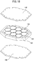
- the two hexagonal columnar shaped oxide superconducting bulk materials with diameter 12 mm holes formed in the center parts were used and were arranged as shown in FIG. 19 .
- hexagonal columnar shape aluminum alloy rings having inside circumference side 30.05 mm and outer circumference side 32.0 mm were used and soldered.
- a SUS314 ring having thickness 14 mm and height 20 mm was used.
- the assembly top reinforcing member a thickness 5.5 mm SUS314 plate having screw holes was used, while as the assembly bottom reinforcing member, a thickness 15.0 mm oxygen-free copper plate having screw holes was used. Furthermore, when joining the assembly top reinforcing member and assembly bottom reinforcing member through an assembly side surface reinforcing member, spacers were arranged in the spaces between the hexagonal columnar shaped oxide superconducting bulk materials with bulk material reinforcing members. In addition, at the holes of the hexagonal columnar shaped oxide superconducting bulk materials formed with the holes as well, spacers were arranged. The assembly top reinforcing member and the assembly bottom reinforcing member were fastened through the spacers. At these positions as well, fastening members were used for fastening to increase the strength and prepare the example oxide superconducting bulk magnet according to this invention (6-C).
- hexagonal columnar shaped oxide superconducting bulk materials having side 30 mm and height 20 mm prepared by the same manner as the above-mentioned manner were used.
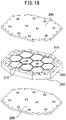
- the two hexagonal columnar shaped oxide superconducting bulk materials with diameter 12 mm holes formed in the center parts were used and were arranged as shown in FIG. 20 .
- hexagonal columnar shape aluminum alloy rings having inside circumference side 30.05 mm and outer circumference side 32.0 mm were used and soldered.
- a SUS314 ring having thickness 14 mm and height 20 mm was used.
- an oxygen-free copper ring having screw holes and worked to correspond to the shape of the end of the assembly (bulk material unit) of the oxide superconducting bulk materials was used. That is, the edge of the assembly side surface reinforcing member at the assembly side was extended so as to contact the side surfaces of the assembly.
- the assembly bottom reinforcing member As the assembly bottom reinforcing member, a thickness 15.0 mm oxygen-free copper plate having screw holes was used. Furthermore, when joining the assembly top reinforcing member and the assembly bottom reinforcing member through the assembly side surface reinforcing member, spacers were arranged in the holes of the two hexagonal columnar shaped oxide superconducting bulk materials formed with holes and the assembly top reinforcing member and assembly bottom reinforcing member were fastened through the spacers. At these positions as well, fastening members were used to join the members to increase the strength and prepare the example oxide superconducting bulk magnet according to this invention (6-D) .
- the shapes of the outer circumferences of the assembly top reinforcing member and assembly bottom reinforcing member are the same as the shape of the outer circumference of the assembly side surface reinforcing member.
- the oxide superconducting bulk materials, bulk material reinforcing members, and assembly side surface reinforcing member were buried in a resin (product name: STYCAST 2850FT, made by Ablestik Japan) so as not to shift during the magnetization test.
- Table 6 shows the presence of breaks in the oxide superconducting bulk materials and the number of the broken hexagonal columnar shaped oxide superconducting bulk materials under the magnetization conditions of various external magnetic fields.
- Table 6 shows the presence of breaks in the oxide superconducting bulk materials and the number of the broken hexagonal columnar shaped oxide superconducting bulk materials under the magnetization conditions of various external magnetic fields.
- Table 6 shows the presence of breaks in the oxide superconducting bulk materials and the number of the broken hexagonal columnar shaped oxide superconducting bulk materials under the magnetization conditions of various external magnetic fields.
Landscapes
- Chemical & Material Sciences (AREA)
- Engineering & Computer Science (AREA)
- Organic Chemistry (AREA)
- Power Engineering (AREA)
- Ceramic Engineering (AREA)
- Inorganic Chemistry (AREA)
- Manufacturing & Machinery (AREA)
- Materials Engineering (AREA)
- Structural Engineering (AREA)
- Inorganic Compounds Of Heavy Metals (AREA)
- Superconductors And Manufacturing Methods Therefor (AREA)
Claims (13)
- Aimant massif supraconducteur à base d'oxyde (10), comprenant une pluralité de matériaux massifs colonnaires supraconducteurs à base d'oxyde (110), chacun desdits matériaux massifs colonnaires supraconducteurs à base d'oxyde ayant une structure à forme monocristalline RE1Ba2Cu3Oy (RE étant un ou plusieurs matériaux sélectionnés entre Y ou des matériaux de terres rares, où 6,8≤y≤7,1) dans laquelle RE2BaCuO5 est dispersé, et présentant une surface supérieure, une surface inférieure, et des surfaces latérales, lesdits matériaux massifs colonnaires supraconducteurs à base d'oxyde étant combinés,où chacune des unités de matériau massif comprend le matériau massif supraconducteur à base d'oxyde (110) et un élément de renforcement de matériau massif (120) disposé de manière à recouvrir les surfaces latérales du matériau massif supraconducteur à base d'oxyde, lesdites unités de matériau massif étant disposées de manière à être orientées dans la même direction et à être en contact l'une avec l'autre pour former un ensemble, où les surfaces latérales de l'ensemble sont recouvertes par un élément de renforcement (130) de surfaces latérales d'ensemble,où l'élément de renforcement de surfaces latérales d'ensemble est plus épais que les éléments de renforcement de matériau massif,où ledit élément de renforcement de matériau massif a une épaisseur égale ou inférieure à 5,0 mm,où une surface supérieure et une surface inférieure de l'ensemble sont recouvertes respectivement par un élément de renforcement (140) de sommet d'ensemble et un élément de renforcement (150) de fond d'ensemble, etoù l'élément de renforcement de surfaces latérales d'ensemble, l'élément de renforcement de sommet d'ensemble, et l'élément de renforcement de fond d'ensemble sont assemblés en une unité intégrée.
- Aimant massif supraconducteur à base d'oxyde selon la revendication 1 où le matériau dont l'élément de renforcement de sommet d'ensemble est constitué est différent du matériau dont l'élément de renforcement de fond d'ensemble est constitué, où la limite d'élasticité de l'élément de renforcement de sommet d'ensemble est supérieure à la limite d'élasticité de l'élément de renforcement de fond d'ensemble à 300 K, et
où la conductivité thermique de l'élément de renforcement de fond d'ensemble est supérieure à la conductivité thermique de l'élément de renforcement de sommet d'ensemble. - Aimant massif supraconducteur à base d'oxyde selon la revendication l ou la revendication 2,où le matériau dont l'élément de renforcement de sommet d'ensemble est constitué est non magnétique et la limite d'élasticité de l'élément de renforcement de sommet d'ensemble à 300 K est égale ou supérieure à 200 MPa, etoù la conductivité thermique du matériau dont l'élément de renforcement de fond d'ensemble est constitué est égale ou supérieure à 50 W/m·K.
- Aimant massif supraconducteur à base d'oxyde selon l'une des revendications 1 à 3,
où la hauteur de l'élément de renforcement de surfaces latérales d'ensemble est égale à la hauteur de l'ensemble ou supérieure à la hauteur de l'ensemble. - Aimant massif supraconducteur à base d'oxyde selon l'une des revendications 1 à 4,
où l'élément de renforcement de surfaces latérales d'ensemble et l'élément de renforcement de sommet d'ensemble et/ou l'élément de renforcement de fond d'ensemble sont une structure intégrée. - Aimant massif supraconducteur à base d'oxyde selon l'une des revendications 1 à 5,
où l'élément de renforcement de surfaces latérales d'ensemble, l'élément de renforcement de sommet d'ensemble et l'élément de renforcement de fond d'ensemble sont assemblés en une seule pièce par des moyens de fixation. - Aimant massif supraconducteur à base d'oxyde selon la revendication 6,où les unités de matériau massif sont disposées de manière à être orientées dans la même direction et être en contact entre elles, etoù l'élément de renforcement de sommet d'ensemble et l'élément de renforcement de fond d'ensemble sont assemblés en une seule pièce par des espaces formés à l'intérieur de l'ensemble.
- Aimant massif supraconducteur à base d'oxyde selon la revendication 6 ou la revendication 7,où les matériaux massifs supraconducteurs à base d'oxyde sont formés avec des orifices traversants (212) ménagés dans une surface supérieure et une surface inférieure, etoù l'élément de renforcement de sommet d'ensemble et l'élément de renforcement de fond d'ensemble sont assemblés en une seule pièce par lesdits orifices traversants.
- Aimant massif supraconducteur à base d'oxyde selon l'une des revendications 1 à 8,
où le matériau massif supraconducteur à base d'oxyde a une forme présentant un polygone, en vue en plan. - Aimant massif supraconducteur à base d'oxyde selon l'une des revendications 1 à 8,
où le matériau massif supraconducteur à base d'oxyde a une forme présentant un polygone à sommets arrondis, en vue en plan. - Aimant massif supraconducteur à base d'oxyde selon la revendication 9 ou la revendication 10,
où la forme polygonale du matériau massif supraconducteur à base d'oxyde est un tétragone, un hexagone ou un octogone. - Aimant massif supraconducteur à base d'oxyde selon l'une des revendications 1 à 8,
où le matériau massif supraconducteur à base d'oxyde a une forme présentant un cercle, en vue en plan. - Aimant massif supraconducteur à base d'oxyde selon l'une des revendications 1 à 8,
où le matériau massif supraconducteur à base d'oxyde a une forme présentant un circuit oblong où sont reliées une paire de droites parallèles opposées et une paire de courbes opposées, en vue en plan.
Applications Claiming Priority (3)
| Application Number | Priority Date | Filing Date | Title |
|---|---|---|---|
| JP2014231388 | 2014-11-14 | ||
| JP2015022384 | 2015-02-06 | ||
| PCT/JP2015/082044 WO2016076433A1 (fr) | 2014-11-14 | 2015-11-13 | Aimant massif supraconducteur à base d'oxyde |
Publications (3)
| Publication Number | Publication Date |
|---|---|
| EP3220397A1 EP3220397A1 (fr) | 2017-09-20 |
| EP3220397A4 EP3220397A4 (fr) | 2018-06-27 |
| EP3220397B1 true EP3220397B1 (fr) | 2022-04-27 |
Family
ID=55954508
Family Applications (1)
| Application Number | Title | Priority Date | Filing Date |
|---|---|---|---|
| EP15858130.6A Active EP3220397B1 (fr) | 2014-11-14 | 2015-11-13 | Aimant massif supraconducteur à base d'oxyde |
Country Status (5)
| Country | Link |
|---|---|
| US (1) | US10283243B2 (fr) |
| EP (1) | EP3220397B1 (fr) |
| JP (1) | JP6324529B2 (fr) |
| CN (1) | CN107210111B (fr) |
| WO (1) | WO2016076433A1 (fr) |
Families Citing this family (6)
| Publication number | Priority date | Publication date | Assignee | Title |
|---|---|---|---|---|
| JP2019091803A (ja) * | 2017-11-15 | 2019-06-13 | 株式会社日立製作所 | 超伝導磁石装置 |
| JP6982522B2 (ja) * | 2018-03-08 | 2021-12-17 | 三菱重工業株式会社 | 超電導回転機械用ステータ、及び超電導回転機械 |
| DE102018216890A1 (de) * | 2018-10-02 | 2020-04-02 | Rolls-Royce Deutschland Ltd & Co Kg | Rotor und Maschine mit supraleitendem Permanentmagneten |
| US11139272B2 (en) | 2019-07-26 | 2021-10-05 | Sandisk Technologies Llc | Bonded assembly containing oxidation barriers and/or adhesion enhancers and methods of forming the same |
| US11393780B2 (en) | 2019-07-26 | 2022-07-19 | Sandisk Technologies Llc | Bonded assembly containing oxidation barriers, hybrid bonding, or air gap, and methods of forming the same |
| US11515273B2 (en) | 2019-07-26 | 2022-11-29 | Sandisk Technologies Llc | Bonded assembly containing oxidation barriers, hybrid bonding, or air gap, and methods of forming the same |
Family Cites Families (13)
| Publication number | Priority date | Publication date | Assignee | Title |
|---|---|---|---|---|
| JPH07182934A (ja) | 1993-12-24 | 1995-07-21 | Hitachi Ltd | バルク状高温超電導導体 |
| JPH09213523A (ja) * | 1996-02-01 | 1997-08-15 | Murata Mfg Co Ltd | 非可逆回路素子 |
| JP3389094B2 (ja) | 1998-03-27 | 2003-03-24 | 株式会社イムラ材料開発研究所 | 超電導磁場発生素子 |
| JP4012311B2 (ja) * | 1998-05-26 | 2007-11-21 | 新日本製鐵株式会社 | バルク超電導部材とマグネットおよびそれらの製造方法 |
| DE19835454A1 (de) * | 1998-08-05 | 2000-02-10 | Aventis Res & Tech Gmbh & Co | Geschütztes supraleitendes Bauteil und Verfahren zu dessen Herstellung |
| JP3671726B2 (ja) | 1999-03-26 | 2005-07-13 | アイシン精機株式会社 | 超電導体の着磁方法及び超電導磁石装置 |
| JP4123649B2 (ja) * | 1999-08-12 | 2008-07-23 | 日立金属株式会社 | 磁界発生装置およびその組立方法 |
| JP2001307916A (ja) | 2000-04-24 | 2001-11-02 | Toshiba Corp | 超電導磁石装置 |
| JP2004349276A (ja) * | 2003-04-25 | 2004-12-09 | Japan Science & Technology Agency | 超電導永久磁石装置 |
| CN2817310Y (zh) * | 2005-08-15 | 2006-09-13 | 广达电脑股份有限公司 | 具有补强构件的电子装置 |
| US8948829B2 (en) | 2009-12-08 | 2015-02-03 | Nippon Steel & Sumitomo Metal Corporation | Oxide superconducting bulk magnet member |
| JP6422631B2 (ja) | 2013-01-30 | 2018-11-14 | 新日鐵住金株式会社 | 超電導バルク磁石 |
| US9324486B2 (en) * | 2013-06-17 | 2016-04-26 | Massachusetts Institute Of Technology | Partial insulation superconducting magnet |
-
2015
- 2015-11-13 EP EP15858130.6A patent/EP3220397B1/fr active Active
- 2015-11-13 WO PCT/JP2015/082044 patent/WO2016076433A1/fr not_active Ceased
- 2015-11-13 JP JP2016559127A patent/JP6324529B2/ja active Active
- 2015-11-13 CN CN201580061567.2A patent/CN107210111B/zh active Active
- 2015-11-13 US US15/526,541 patent/US10283243B2/en active Active
Also Published As
| Publication number | Publication date |
|---|---|
| JPWO2016076433A1 (ja) | 2017-08-31 |
| US20170316859A1 (en) | 2017-11-02 |
| US10283243B2 (en) | 2019-05-07 |
| EP3220397A1 (fr) | 2017-09-20 |
| CN107210111B (zh) | 2019-10-01 |
| EP3220397A4 (fr) | 2018-06-27 |
| JP6324529B2 (ja) | 2018-05-23 |
| WO2016076433A1 (fr) | 2016-05-19 |
| CN107210111A (zh) | 2017-09-26 |
Similar Documents
| Publication | Publication Date | Title |
|---|---|---|
| EP3220397B1 (fr) | Aimant massif supraconducteur à base d'oxyde | |
| CN102640234B (zh) | 氧化物超导块材磁体构件 | |
| CN107112108B (zh) | 氧化物超导块状磁铁 | |
| JP7377703B2 (ja) | 超伝導線材、超伝導線材の製造方法およびmri装置 | |
| US20160155554A1 (en) | Oxide superconducting bulk magnet | |
| JP2004192934A (ja) | 超電導線材およびその製法 | |
| EP2642543A1 (fr) | Fils multiconducteur supraconducteurs MGB2, câbles supraconducteurs et aimants supraconducteurs | |
| JP4719308B1 (ja) | 酸化物超伝導バルク磁石部材 | |
| JP2012074330A (ja) | 超電導線材の製造方法、および超電導線材 | |
| JP5736216B2 (ja) | 超伝導バルク体とその製造方法および超伝導バルク磁石 | |
| JP5195961B2 (ja) | 酸化物超伝導バルク磁石部材 | |
| EP3358581B1 (fr) | Aimant massif supraconducteur à base d'oxyde | |
| JP4799979B2 (ja) | 酸化物超伝導体コイル、酸化物超伝導体コイルの製造方法、酸化物超伝導体コイルの励磁方法、酸化物超伝導体コイルの冷却方法、及びマグネットシステム | |
| JP4903729B2 (ja) | 酸化物超伝導マグネット及びその製造方法、並びに冷却方法 | |
| US20160329138A1 (en) | Oxide superconducting bulk magnet | |
| Kikuchi et al. | Strand and Cable Development for a High Field ${\rm Nb} _ {3}{\rm Al} $ Common Coil Magnet | |
| EP0734081A1 (fr) | Fil en oxyde supraconducteur et procédé de fabrication | |
| JPH0334398A (ja) | 電磁シールド体及びその製造方法 |
Legal Events
| Date | Code | Title | Description |
|---|---|---|---|
| STAA | Information on the status of an ep patent application or granted ep patent |
Free format text: STATUS: THE INTERNATIONAL PUBLICATION HAS BEEN MADE |
|
| PUAI | Public reference made under article 153(3) epc to a published international application that has entered the european phase |
Free format text: ORIGINAL CODE: 0009012 |
|
| STAA | Information on the status of an ep patent application or granted ep patent |
Free format text: STATUS: REQUEST FOR EXAMINATION WAS MADE |
|
| 17P | Request for examination filed |
Effective date: 20170612 |
|
| AK | Designated contracting states |
Kind code of ref document: A1 Designated state(s): AL AT BE BG CH CY CZ DE DK EE ES FI FR GB GR HR HU IE IS IT LI LT LU LV MC MK MT NL NO PL PT RO RS SE SI SK SM TR |
|
| AX | Request for extension of the european patent |
Extension state: BA ME |
|
| DAV | Request for validation of the european patent (deleted) | ||
| DAX | Request for extension of the european patent (deleted) | ||
| A4 | Supplementary search report drawn up and despatched |
Effective date: 20180529 |
|
| RIC1 | Information provided on ipc code assigned before grant |
Ipc: H01F 6/00 20060101AFI20180523BHEP Ipc: C01G 3/00 20060101ALI20180523BHEP Ipc: C01G 1/00 20060101ALI20180523BHEP Ipc: H01B 12/02 20060101ALI20180523BHEP Ipc: H01F 1/11 20060101ALI20180523BHEP |
|
| RAP1 | Party data changed (applicant data changed or rights of an application transferred) |
Owner name: NIPPON STEEL CORPORATION Owner name: NATIONAL UNIVERSITY CORPORATION TOKYO UNIVERSITY O |
|
| STAA | Information on the status of an ep patent application or granted ep patent |
Free format text: STATUS: EXAMINATION IS IN PROGRESS |
|
| 17Q | First examination report despatched |
Effective date: 20200326 |
|
| GRAP | Despatch of communication of intention to grant a patent |
Free format text: ORIGINAL CODE: EPIDOSNIGR1 |
|
| STAA | Information on the status of an ep patent application or granted ep patent |
Free format text: STATUS: GRANT OF PATENT IS INTENDED |
|
| INTG | Intention to grant announced |
Effective date: 20211110 |
|
| GRAS | Grant fee paid |
Free format text: ORIGINAL CODE: EPIDOSNIGR3 |
|
| GRAA | (expected) grant |
Free format text: ORIGINAL CODE: 0009210 |
|
| STAA | Information on the status of an ep patent application or granted ep patent |
Free format text: STATUS: THE PATENT HAS BEEN GRANTED |
|
| AK | Designated contracting states |
Kind code of ref document: B1 Designated state(s): AL AT BE BG CH CY CZ DE DK EE ES FI FR GB GR HR HU IE IS IT LI LT LU LV MC MK MT NL NO PL PT RO RS SE SI SK SM TR |
|
| REG | Reference to a national code |
Ref country code: GB Ref legal event code: FG4D |
|
| REG | Reference to a national code |
Ref country code: CH Ref legal event code: EP |
|
| REG | Reference to a national code |
Ref country code: AT Ref legal event code: REF Ref document number: 1487587 Country of ref document: AT Kind code of ref document: T Effective date: 20220515 |
|
| REG | Reference to a national code |
Ref country code: DE Ref legal event code: R096 Ref document number: 602015078576 Country of ref document: DE |
|
| REG | Reference to a national code |
Ref country code: IE Ref legal event code: FG4D |
|
| REG | Reference to a national code |
Ref country code: LT Ref legal event code: MG9D |
|
| REG | Reference to a national code |
Ref country code: NL Ref legal event code: MP Effective date: 20220427 |
|
| REG | Reference to a national code |
Ref country code: AT Ref legal event code: MK05 Ref document number: 1487587 Country of ref document: AT Kind code of ref document: T Effective date: 20220427 |
|
| PG25 | Lapsed in a contracting state [announced via postgrant information from national office to epo] |
Ref country code: NL Free format text: LAPSE BECAUSE OF FAILURE TO SUBMIT A TRANSLATION OF THE DESCRIPTION OR TO PAY THE FEE WITHIN THE PRESCRIBED TIME-LIMIT Effective date: 20220427 |
|
| PG25 | Lapsed in a contracting state [announced via postgrant information from national office to epo] |
Ref country code: SE Free format text: LAPSE BECAUSE OF FAILURE TO SUBMIT A TRANSLATION OF THE DESCRIPTION OR TO PAY THE FEE WITHIN THE PRESCRIBED TIME-LIMIT Effective date: 20220427 Ref country code: PT Free format text: LAPSE BECAUSE OF FAILURE TO SUBMIT A TRANSLATION OF THE DESCRIPTION OR TO PAY THE FEE WITHIN THE PRESCRIBED TIME-LIMIT Effective date: 20220829 Ref country code: NO Free format text: LAPSE BECAUSE OF FAILURE TO SUBMIT A TRANSLATION OF THE DESCRIPTION OR TO PAY THE FEE WITHIN THE PRESCRIBED TIME-LIMIT Effective date: 20220727 Ref country code: LT Free format text: LAPSE BECAUSE OF FAILURE TO SUBMIT A TRANSLATION OF THE DESCRIPTION OR TO PAY THE FEE WITHIN THE PRESCRIBED TIME-LIMIT Effective date: 20220427 Ref country code: HR Free format text: LAPSE BECAUSE OF FAILURE TO SUBMIT A TRANSLATION OF THE DESCRIPTION OR TO PAY THE FEE WITHIN THE PRESCRIBED TIME-LIMIT Effective date: 20220427 Ref country code: GR Free format text: LAPSE BECAUSE OF FAILURE TO SUBMIT A TRANSLATION OF THE DESCRIPTION OR TO PAY THE FEE WITHIN THE PRESCRIBED TIME-LIMIT Effective date: 20220728 Ref country code: FI Free format text: LAPSE BECAUSE OF FAILURE TO SUBMIT A TRANSLATION OF THE DESCRIPTION OR TO PAY THE FEE WITHIN THE PRESCRIBED TIME-LIMIT Effective date: 20220427 Ref country code: ES Free format text: LAPSE BECAUSE OF FAILURE TO SUBMIT A TRANSLATION OF THE DESCRIPTION OR TO PAY THE FEE WITHIN THE PRESCRIBED TIME-LIMIT Effective date: 20220427 Ref country code: BG Free format text: LAPSE BECAUSE OF FAILURE TO SUBMIT A TRANSLATION OF THE DESCRIPTION OR TO PAY THE FEE WITHIN THE PRESCRIBED TIME-LIMIT Effective date: 20220727 Ref country code: AT Free format text: LAPSE BECAUSE OF FAILURE TO SUBMIT A TRANSLATION OF THE DESCRIPTION OR TO PAY THE FEE WITHIN THE PRESCRIBED TIME-LIMIT Effective date: 20220427 |
|
| PG25 | Lapsed in a contracting state [announced via postgrant information from national office to epo] |
Ref country code: RS Free format text: LAPSE BECAUSE OF FAILURE TO SUBMIT A TRANSLATION OF THE DESCRIPTION OR TO PAY THE FEE WITHIN THE PRESCRIBED TIME-LIMIT Effective date: 20220427 Ref country code: PL Free format text: LAPSE BECAUSE OF FAILURE TO SUBMIT A TRANSLATION OF THE DESCRIPTION OR TO PAY THE FEE WITHIN THE PRESCRIBED TIME-LIMIT Effective date: 20220427 Ref country code: LV Free format text: LAPSE BECAUSE OF FAILURE TO SUBMIT A TRANSLATION OF THE DESCRIPTION OR TO PAY THE FEE WITHIN THE PRESCRIBED TIME-LIMIT Effective date: 20220427 Ref country code: IS Free format text: LAPSE BECAUSE OF FAILURE TO SUBMIT A TRANSLATION OF THE DESCRIPTION OR TO PAY THE FEE WITHIN THE PRESCRIBED TIME-LIMIT Effective date: 20220827 |
|
| REG | Reference to a national code |
Ref country code: DE Ref legal event code: R097 Ref document number: 602015078576 Country of ref document: DE |
|
| PG25 | Lapsed in a contracting state [announced via postgrant information from national office to epo] |
Ref country code: SM Free format text: LAPSE BECAUSE OF FAILURE TO SUBMIT A TRANSLATION OF THE DESCRIPTION OR TO PAY THE FEE WITHIN THE PRESCRIBED TIME-LIMIT Effective date: 20220427 Ref country code: SK Free format text: LAPSE BECAUSE OF FAILURE TO SUBMIT A TRANSLATION OF THE DESCRIPTION OR TO PAY THE FEE WITHIN THE PRESCRIBED TIME-LIMIT Effective date: 20220427 Ref country code: RO Free format text: LAPSE BECAUSE OF FAILURE TO SUBMIT A TRANSLATION OF THE DESCRIPTION OR TO PAY THE FEE WITHIN THE PRESCRIBED TIME-LIMIT Effective date: 20220427 Ref country code: EE Free format text: LAPSE BECAUSE OF FAILURE TO SUBMIT A TRANSLATION OF THE DESCRIPTION OR TO PAY THE FEE WITHIN THE PRESCRIBED TIME-LIMIT Effective date: 20220427 Ref country code: DK Free format text: LAPSE BECAUSE OF FAILURE TO SUBMIT A TRANSLATION OF THE DESCRIPTION OR TO PAY THE FEE WITHIN THE PRESCRIBED TIME-LIMIT Effective date: 20220427 Ref country code: CZ Free format text: LAPSE BECAUSE OF FAILURE TO SUBMIT A TRANSLATION OF THE DESCRIPTION OR TO PAY THE FEE WITHIN THE PRESCRIBED TIME-LIMIT Effective date: 20220427 |
|
| PLBE | No opposition filed within time limit |
Free format text: ORIGINAL CODE: 0009261 |
|
| STAA | Information on the status of an ep patent application or granted ep patent |
Free format text: STATUS: NO OPPOSITION FILED WITHIN TIME LIMIT |
|
| PG25 | Lapsed in a contracting state [announced via postgrant information from national office to epo] |
Ref country code: AL Free format text: LAPSE BECAUSE OF FAILURE TO SUBMIT A TRANSLATION OF THE DESCRIPTION OR TO PAY THE FEE WITHIN THE PRESCRIBED TIME-LIMIT Effective date: 20220427 |
|
| 26N | No opposition filed |
Effective date: 20230130 |
|
| PG25 | Lapsed in a contracting state [announced via postgrant information from national office to epo] |
Ref country code: SI Free format text: LAPSE BECAUSE OF FAILURE TO SUBMIT A TRANSLATION OF THE DESCRIPTION OR TO PAY THE FEE WITHIN THE PRESCRIBED TIME-LIMIT Effective date: 20220427 |
|
| REG | Reference to a national code |
Ref country code: DE Ref legal event code: R119 Ref document number: 602015078576 Country of ref document: DE |
|
| PG25 | Lapsed in a contracting state [announced via postgrant information from national office to epo] |
Ref country code: MC Free format text: LAPSE BECAUSE OF FAILURE TO SUBMIT A TRANSLATION OF THE DESCRIPTION OR TO PAY THE FEE WITHIN THE PRESCRIBED TIME-LIMIT Effective date: 20220427 |
|
| GBPC | Gb: european patent ceased through non-payment of renewal fee |
Effective date: 20221113 |
|
| REG | Reference to a national code |
Ref country code: BE Ref legal event code: MM Effective date: 20221130 |
|
| PG25 | Lapsed in a contracting state [announced via postgrant information from national office to epo] |
Ref country code: LU Free format text: LAPSE BECAUSE OF NON-PAYMENT OF DUE FEES Effective date: 20221113 |
|
| PG25 | Lapsed in a contracting state [announced via postgrant information from national office to epo] |
Ref country code: IE Free format text: LAPSE BECAUSE OF NON-PAYMENT OF DUE FEES Effective date: 20221113 Ref country code: GB Free format text: LAPSE BECAUSE OF NON-PAYMENT OF DUE FEES Effective date: 20221113 Ref country code: DE Free format text: LAPSE BECAUSE OF NON-PAYMENT OF DUE FEES Effective date: 20230601 |
|
| PG25 | Lapsed in a contracting state [announced via postgrant information from national office to epo] |
Ref country code: FR Free format text: LAPSE BECAUSE OF NON-PAYMENT OF DUE FEES Effective date: 20221130 Ref country code: BE Free format text: LAPSE BECAUSE OF NON-PAYMENT OF DUE FEES Effective date: 20221130 |
|
| PG25 | Lapsed in a contracting state [announced via postgrant information from national office to epo] |
Ref country code: IT Free format text: LAPSE BECAUSE OF FAILURE TO SUBMIT A TRANSLATION OF THE DESCRIPTION OR TO PAY THE FEE WITHIN THE PRESCRIBED TIME-LIMIT Effective date: 20220427 |
|
| PG25 | Lapsed in a contracting state [announced via postgrant information from national office to epo] |
Ref country code: HU Free format text: LAPSE BECAUSE OF FAILURE TO SUBMIT A TRANSLATION OF THE DESCRIPTION OR TO PAY THE FEE WITHIN THE PRESCRIBED TIME-LIMIT; INVALID AB INITIO Effective date: 20151113 |
|
| PG25 | Lapsed in a contracting state [announced via postgrant information from national office to epo] |
Ref country code: CY Free format text: LAPSE BECAUSE OF FAILURE TO SUBMIT A TRANSLATION OF THE DESCRIPTION OR TO PAY THE FEE WITHIN THE PRESCRIBED TIME-LIMIT Effective date: 20220427 |
|
| PG25 | Lapsed in a contracting state [announced via postgrant information from national office to epo] |
Ref country code: MK Free format text: LAPSE BECAUSE OF FAILURE TO SUBMIT A TRANSLATION OF THE DESCRIPTION OR TO PAY THE FEE WITHIN THE PRESCRIBED TIME-LIMIT Effective date: 20220427 |
|
| PG25 | Lapsed in a contracting state [announced via postgrant information from national office to epo] |
Ref country code: MT Free format text: LAPSE BECAUSE OF FAILURE TO SUBMIT A TRANSLATION OF THE DESCRIPTION OR TO PAY THE FEE WITHIN THE PRESCRIBED TIME-LIMIT Effective date: 20220427 |
|
| PG25 | Lapsed in a contracting state [announced via postgrant information from national office to epo] |
Ref country code: BG Free format text: LAPSE BECAUSE OF FAILURE TO SUBMIT A TRANSLATION OF THE DESCRIPTION OR TO PAY THE FEE WITHIN THE PRESCRIBED TIME-LIMIT Effective date: 20220427 |
|
| PG25 | Lapsed in a contracting state [announced via postgrant information from national office to epo] |
Ref country code: BG Free format text: LAPSE BECAUSE OF FAILURE TO SUBMIT A TRANSLATION OF THE DESCRIPTION OR TO PAY THE FEE WITHIN THE PRESCRIBED TIME-LIMIT Effective date: 20220427 |
|
| REG | Reference to a national code |
Ref country code: CH Ref legal event code: U11 Free format text: ST27 STATUS EVENT CODE: U-0-0-U10-U11 (AS PROVIDED BY THE NATIONAL OFFICE) Effective date: 20251201 |
|
| PG25 | Lapsed in a contracting state [announced via postgrant information from national office to epo] |
Ref country code: TR Free format text: LAPSE BECAUSE OF FAILURE TO SUBMIT A TRANSLATION OF THE DESCRIPTION OR TO PAY THE FEE WITHIN THE PRESCRIBED TIME-LIMIT Effective date: 20220427 |
|
| PGFP | Annual fee paid to national office [announced via postgrant information from national office to epo] |
Ref country code: CH Payment date: 20251201 Year of fee payment: 11 |