EP3220515A1 - Zerlegbarer elektromotor - Google Patents
Zerlegbarer elektromotor Download PDFInfo
- Publication number
- EP3220515A1 EP3220515A1 EP17161871.3A EP17161871A EP3220515A1 EP 3220515 A1 EP3220515 A1 EP 3220515A1 EP 17161871 A EP17161871 A EP 17161871A EP 3220515 A1 EP3220515 A1 EP 3220515A1
- Authority
- EP
- European Patent Office
- Prior art keywords
- housing
- rolling device
- shaft
- electric motor
- centering
- Prior art date
- Legal status (The legal status is an assumption and is not a legal conclusion. Google has not performed a legal analysis and makes no representation as to the accuracy of the status listed.)
- Granted
Links
Images


Classifications
-
- H—ELECTRICITY
- H02—GENERATION; CONVERSION OR DISTRIBUTION OF ELECTRIC POWER
- H02K—DYNAMO-ELECTRIC MACHINES
- H02K5/00—Casings; Enclosures; Supports
- H02K5/04—Casings or enclosures characterised by the shape, form or construction thereof
- H02K5/15—Mounting arrangements for bearing-shields or end plates
-
- H—ELECTRICITY
- H02—GENERATION; CONVERSION OR DISTRIBUTION OF ELECTRIC POWER
- H02K—DYNAMO-ELECTRIC MACHINES
- H02K15/00—Processes or apparatus specially adapted for manufacturing, assembling, maintaining or repairing of dynamo-electric machines
- H02K15/50—Disassembling, repairing or modifying dynamo-electric machines
-
- H—ELECTRICITY
- H02—GENERATION; CONVERSION OR DISTRIBUTION OF ELECTRIC POWER
- H02K—DYNAMO-ELECTRIC MACHINES
- H02K5/00—Casings; Enclosures; Supports
- H02K5/04—Casings or enclosures characterised by the shape, form or construction thereof
- H02K5/16—Means for supporting bearings, e.g. insulating supports or means for fitting bearings in the bearing-shields
- H02K5/173—Means for supporting bearings, e.g. insulating supports or means for fitting bearings in the bearing-shields using bearings with rolling contact, e.g. ball bearings
- H02K5/1732—Means for supporting bearings, e.g. insulating supports or means for fitting bearings in the bearing-shields using bearings with rolling contact, e.g. ball bearings radially supporting the rotary shaft at both ends of the rotor
Definitions
- Electric motors of this type are used in particular for the propulsion of railway vehicles. They are located at the level of bogies and receive electrical power supplied by a current generator or directly supplied by a high-voltage line. They convert this electrical power into mechanical power intended to drive the wheels in rotation, by means of the rotation of a rotor driving a shaft carried by bearings and causing itself to rotate one or more wheels, for example by through a gearbox.
- Rolling bearings of electric motors require regular maintenance, such as a renewal of the lubricating grease or a change of worn rolling parts, in order to avoid a decrease in performance, for example because of a seizing of the bearings, or damage to the engine.
- the disassembly of the rolling devices for their maintenance or replacement generally requires disassembly of the rotor with its shaft to allow the extraction of the bearing. Therefore, the maintenance or replacement time of bearings is important and requires the intervention of qualified personnel and specific handling means.
- the presence of permanent magnets on the rotor makes the operation even more complex, and is a source of accident risk for operators or damage to the engine during handling.
- An object of the invention is thus to provide a bearing device fitted to an electric motor and to disassemble the bearings without requiring disassembly of the rest of the rotating part of the engine.
- the subject of the invention is an electric motor of the aforementioned type, characterized in that the rolling device is movable between a mounting position, in which at least one centering bearing surface of the rolling device bears against at least one centering span of the housing so that the rolling device is fixed to the housing in the mounting position, and a disassembly position, in which the centering bearing surface of the rolling device is arranged opposite a housing cavity and the bearing centering the housing is arranged opposite a cavity of the device of rolling, so that the rolling device is movable in translation along the axis relative to the housing and the shaft, in disassembly position.
- An engine of this type makes it possible to extract the bearing by sliding it along the shaft, without having to disassemble the rotor with its shaft.
- An engine 10 shown on the figure 1 transforms an electrical power into mechanical power by the rotation of a rotor 12 driven by a stator 14 electrically powered.
- the rotor 12 and the stator 14 are separated by an air gap whose width is denoted e.
- the rotor 12 is carried by a shaft 16, itself carried by at least one rolling device 18.
- the motor 10 represented on the figure 1 is schematic and not all elements of it have been represented.
- the motor 10 also comprises, inter alia, a cooling circuit and electrical supply means connected to the stator 14.
- each end flange 22 is closed by the rolling device 18 which comprises a housing 23 containing a rolling bearing 24.
- the shaft 16 carrying the rotor 12 is substantially cylindrical, extending along a longitudinal axis A-A ', and free to rotate with respect to the housing 20, about the axis AA' thanks to the action of the or rolling bearings 24.
- the rolling bearing 24 comprises an inner ring 26 and an outer ring 28 enclosing a plurality of rolling elements 30.
- the inner ring 26 is clamped around the shaft 16, bearing on a shoulder 32 of the shaft 16 which blocks its axial displacement.
- the outer ring 28 is contained in the housing 23, and positioned facing the inner ring 26.
- the rolling elements 30 are metal balls, free to roll in the rail formed by the inner ring 26 and the outer ring 28 with friction reduced by the addition of a lubricant.
- the inner ring is rotatable about the axis AA 'relative to the outer ring.
- the rolling elements 30 are metal cylinders whose axes are parallel to the axis AA 'of the shaft 16.
- the housing 23 is held fixed to the flange 22, bearing on a shoulder 34 of the housing 23, for example by means of screws passing through orifices 36 drilled in the shoulder 34, and engaged in threads 38 of the end flange 22.
- the housing 23 has at least one cavity 40, on a portion of a circumferential contact surface with the flange 22, for example recessed sectors.
- sector recessed we mean that the distance between the wall of the cavity 40 and the axis AA 'is smaller than the distance between the axis AA' and the circumferential wall of the rest of the housing 23.
- the flange 22 has at least one cavity 42, for example recessed areas, on a part of the circumferential contact surface with the housing 23.
- this time means that the distance between the wall of the cavity 42 and the axis AA 'is larger than the distance between the axis AA' and the circumferential wall of the remainder of the flange 22.
- the housing 23 also has at least one centering surface 44 on the remainder of the circumferential contact surface with the flange 22, and the flange 22 likewise has at least one centering surface 46 on the remainder of the circumferential contact surface. with the housing 23.
- the distance between the axis AA 'and the centering surface 44 of the housing 23 is substantially equal to the distance between the axis AA' and the centering surface 46 of the flange 22.
- This distance between the axis AA 'and the centering bearings 44, 46 is greater than the distance between the axis AA' and the wall of the cavity 40 of the housing 23, and less than the distance between the axis AA 'and the wall of the cavity 42 flange 22.
- the housing 23 and the flange 22 have several recessed sectors 40, 42 and several centering surfaces 44, 46 distributed regularly around the axis A-A '.
- the housing 23 and the flange 22 have the same number of recessed sectors 40, 42 and centering bearings 44, 46, alternately distributed over their respective circumferences.
- Each of the recessed sectors 40, 42 and centering spans are separated by the same angle measured around the axis A-A '.
- the housing 23 and the flange 22 each have three recessed sectors 40, 42, and three centering lands 44, 46, each extending over an angular sector of 60 ° measured with respect to the axis.
- A-A ' alternately distributed every 60 ° around the axis A-A'.
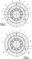
- the housing 23 can be moved between a mounting configuration, shown on the figures 2 and 3 , and a disassembly configuration shown on the figure 4 .
- the recessed sectors 40 of the housing 23 are arranged facing the recessed sectors 42 of the flange 22, and cooperate to form conduits 48.
- the centering bearing surfaces 44 of the housing 23 are then arranged in abutment against the centering bearings 46 of the flange 22.
- the centering of the axis 16 and the fixing of the housing 23 to the housing 20 are then provided by the cooperation of the centering surfaces 44, 46, allowing the electric motor 10 to operate optimally. Indeed, the rotation of the shaft 16 relative to the casing 20 is then allowed by the rotation of the inner ring 26 of the rolling bearing 24 in the outer ring 28 thanks to the rolling elements 30.
- the housing 23 can be passed in disassembly configuration by a rotation of 60 ° around the axis A-A 'starting from the mounting configuration.
- the centering bearing surfaces 44 of the housing 23 are facing the recessed sectors 42 of the flange 22, and the centering bearing surfaces 46 of the flange 22 are facing recessed sectors 40 of the housing 23.
- the housing 23 and the flange 22 then have a clearance between them whose width is noted j.
- the clearance between the housing 23 and the flange 22 is sufficient to axially move the housing 23 along the shaft 16, to the free end of the shaft 16, to disassemble the rolling bearing 24 for the purpose of maintenance or replacement.
- the housing 23 contains, in addition to the rolling bearing 24, a fixed deflector 50, which bears axially against the outer ring 28 of the bearing.
- the fixed deflector 50 is positioned between the housing 23 and a rotating spacer 52 associated with the shaft 16 and surrounding the shaft 16.
- the tightness of the casing 20 is furthermore reinforced by an internal deflector 54 and an external deflector 56, both of which are clamped around the shaft 16.
- the casing 23 has internal grooves 57 on its internal face which extend circumferentially around each other. the axis A-A '.
- the internal deflector 54 has ribs parallel to the grooves 57, which penetrate into the grooves 57 to form a set of internal sealing baffles 58.
- the housing 23 is closed by a cover 60 which has external grooves 61 which extend circumferentially around the axis A-A '.
- the outer baffle 56 has ribs parallel to the grooves 61, which penetrate the grooves 61 to form an outer baffle assembly 62 as shown. figure 2 .
- the housing 20 advantageously comprises a pre-centering ring 64, fixed or integrated to the flange 22.
- This pre-centering ring 64 is configured to carry the shaft 16 bearing on the inner baffle 54, in the disassembly position when the case 23 is removed.
- the pre-centering ring 64 has a shoulder 66 for centering it in the flange 22.
- the ring 64 can directly carry the shaft 16 in the disassembly position when the casing 23 is removed.
- the housing 10 is devoid of pre-centering ring 64.
- the stator 14 has a bore configured to directly carry the shaft 16 in disassembly position when the housing 23 is removed.
- the clearance j between the housing 23 and the flange 22 is greater than the air gap e separating the stator 14 from the rotor 12.
- each cavity 40 and each centering surface 44 is located on the circumferential wall of the shoulder 34, and is intended to cooperate with the flange 22 in mounting configuration.
- each cavity 42 and each centering surface 46 is located on the inner wall of the flange 22 facing the circumferential wall of the shoulder 34.
- the conduits 48 are therefore, in the mounting position, at the level of the Shoulder 34.
- the invention described allows the provision of an electric motor whose bearings are easily removable for maintenance or replacement. Disassembly does not require in particular removal of the shaft and removal of the rotor, which is a complex step requiring qualified personnel and important security means.
- the engine according to the invention thus makes it possible to save significant personnel and equipment.
Landscapes
- Engineering & Computer Science (AREA)
- Power Engineering (AREA)
- Manufacturing & Machinery (AREA)
- Motor Or Generator Frames (AREA)
- Rolling Contact Bearings (AREA)
- Mounting Of Bearings Or Others (AREA)
Applications Claiming Priority (1)
| Application Number | Priority Date | Filing Date | Title |
|---|---|---|---|
| FR1652346A FR3049126B1 (fr) | 2016-03-18 | 2016-03-18 | Moteur electrique demontable |
Publications (2)
| Publication Number | Publication Date |
|---|---|
| EP3220515A1 true EP3220515A1 (de) | 2017-09-20 |
| EP3220515B1 EP3220515B1 (de) | 2020-11-25 |
Family
ID=56119544
Family Applications (1)
| Application Number | Title | Priority Date | Filing Date |
|---|---|---|---|
| EP17161871.3A Active EP3220515B1 (de) | 2016-03-18 | 2017-03-20 | Zerlegbarer elektromotor |
Country Status (5)
| Country | Link |
|---|---|
| EP (1) | EP3220515B1 (de) |
| JP (1) | JP7195723B2 (de) |
| CN (1) | CN107404177B (de) |
| ES (1) | ES2854753T3 (de) |
| FR (1) | FR3049126B1 (de) |
Cited By (1)
| Publication number | Priority date | Publication date | Assignee | Title |
|---|---|---|---|---|
| CN115632523A (zh) * | 2022-09-07 | 2023-01-20 | 扬州市华胜机电科技有限公司 | 一种便于外壳拆装的电动机 |
Families Citing this family (2)
| Publication number | Priority date | Publication date | Assignee | Title |
|---|---|---|---|---|
| JP7302235B2 (ja) * | 2019-03-29 | 2023-07-04 | 株式会社デンソー | 回転電機 |
| JP7252056B2 (ja) * | 2019-05-21 | 2023-04-04 | 株式会社日立産機システム | リニアモータ及びこのリニアモータを用いたリニア圧縮機、並びにリニア圧縮機を用いたエアサスペンション |
Citations (4)
| Publication number | Priority date | Publication date | Assignee | Title |
|---|---|---|---|---|
| EP1460747A1 (de) * | 2003-03-19 | 2004-09-22 | Minebea Co., Ltd. | Lagerungshalter und Gehäuse eines Elektromotors |
| US20120062076A1 (en) * | 2010-09-09 | 2012-03-15 | Takashi Nagayama | Motor |
| US20150123517A1 (en) * | 2012-05-29 | 2015-05-07 | Mitsubishi Electric Corporation | Rotary electric machine and bearing changing method |
| FR3024611A1 (fr) * | 2014-08-01 | 2016-02-05 | Alstom Transp Tech | Moteur electrique et procede de demontage |
Family Cites Families (2)
| Publication number | Priority date | Publication date | Assignee | Title |
|---|---|---|---|---|
| DE102005030217A1 (de) * | 2005-06-29 | 2007-01-04 | Robert Bosch Gmbh | Elektromotor und Getriebe-Antriebseinheit für Stellantriebe im Kraftfahrzeug |
| JP5958048B2 (ja) * | 2012-04-26 | 2016-07-27 | 富士電機株式会社 | 回転電機の軸受支持構造 |
-
2016
- 2016-03-18 FR FR1652346A patent/FR3049126B1/fr not_active Expired - Fee Related
-
2017
- 2017-03-17 CN CN201710161838.2A patent/CN107404177B/zh active Active
- 2017-03-17 JP JP2017052485A patent/JP7195723B2/ja active Active
- 2017-03-20 EP EP17161871.3A patent/EP3220515B1/de active Active
- 2017-03-20 ES ES17161871T patent/ES2854753T3/es active Active
Patent Citations (4)
| Publication number | Priority date | Publication date | Assignee | Title |
|---|---|---|---|---|
| EP1460747A1 (de) * | 2003-03-19 | 2004-09-22 | Minebea Co., Ltd. | Lagerungshalter und Gehäuse eines Elektromotors |
| US20120062076A1 (en) * | 2010-09-09 | 2012-03-15 | Takashi Nagayama | Motor |
| US20150123517A1 (en) * | 2012-05-29 | 2015-05-07 | Mitsubishi Electric Corporation | Rotary electric machine and bearing changing method |
| FR3024611A1 (fr) * | 2014-08-01 | 2016-02-05 | Alstom Transp Tech | Moteur electrique et procede de demontage |
Cited By (2)
| Publication number | Priority date | Publication date | Assignee | Title |
|---|---|---|---|---|
| CN115632523A (zh) * | 2022-09-07 | 2023-01-20 | 扬州市华胜机电科技有限公司 | 一种便于外壳拆装的电动机 |
| CN115632523B (zh) * | 2022-09-07 | 2023-10-20 | 扬州市华胜机电科技有限公司 | 一种便于外壳拆装的电动机 |
Also Published As
| Publication number | Publication date |
|---|---|
| JP2017175905A (ja) | 2017-09-28 |
| JP7195723B2 (ja) | 2022-12-26 |
| CN107404177B (zh) | 2021-01-05 |
| CN107404177A (zh) | 2017-11-28 |
| FR3049126B1 (fr) | 2020-12-04 |
| EP3220515B1 (de) | 2020-11-25 |
| ES2854753T3 (es) | 2021-09-22 |
| FR3049126A1 (fr) | 2017-09-22 |
Similar Documents
| Publication | Publication Date | Title |
|---|---|---|
| EP4348012B1 (de) | Turbomaschine mit integrierter elektrischer maschine im hinteren bereich | |
| EP3645903B1 (de) | Antriebsanordnung für eine elektrische drehmaschine eines kraftfahrzeuges | |
| FR3087226A1 (fr) | Turbomachine d'aeronef a reducteur mecanique et a turbine contrarotative | |
| EP3220515B1 (de) | Zerlegbarer elektromotor | |
| FR2851377A1 (fr) | Machine dynamoelectrique | |
| EP3007331A1 (de) | Elektromotor und sein demontageverfahren | |
| EP2576995A2 (de) | Getriebe einer turbomaschine | |
| EP4107371B1 (de) | Vorrichtung zur verteilung von öl aus einem wälzlager für ein flugzeugturbinentriebwerk | |
| EP4069945B1 (de) | Starre stange zur elektrischen verbindung einer maschine in einem flugtriebwerk | |
| EP2723995B1 (de) | Zusätzliches relais mit verlängerter lebensdauer | |
| CA3091871A1 (fr) | Turbopropulseur comprenant une generatrice d'electricite integree | |
| EP2186705B1 (de) | Instrumentiertes Wälzlager für Schienenfahrzeugsachse und entsprechendes Montageverfahren | |
| EP3601747B1 (de) | Anbaugerätegetriebe für einen gasturbinenmotor | |
| EP3819148A1 (de) | Kühlvorrichtung für einen elektrischen antriebsmotor eines fahrzeugs, entsprechende antriebsanordnung, entsprechendes fahrzeug und austauschverfahren | |
| EP3817201A1 (de) | Elektrischer antriebsmotor eines fahrzeugs | |
| FR2915032A1 (fr) | Machine tournante antideflagrante | |
| FR3124543A1 (fr) | Turbomachine d’aeronef equipee d’une machine electrique | |
| FR2980538A1 (fr) | Groupe moto-compresseur a cartouche amovible | |
| FR3097912A1 (fr) | Machine electrique tournante munie d'un organe de precontrainte de roulement | |
| FR3084977A1 (fr) | Moteur electrique pour un aeronef | |
| WO2016207544A1 (fr) | Support de roulements | |
| FR3147247A1 (fr) | Dispositif de compensation pour le verrouillage axial d’un premier élément tubulaire reçu à ajustement dans un deuxième élément tubulaire | |
| WO2017134376A1 (fr) | Ensemble poulie pour une machine electrique tournante | |
| WO2025215316A1 (fr) | Turbomachine equipee d'une machine electrique deconnectable et d'un organe d'appui pour sa deconnexion | |
| FR3138859A1 (fr) | Rotor de machine électrique avec canal de refroidissement |
Legal Events
| Date | Code | Title | Description |
|---|---|---|---|
| PUAI | Public reference made under article 153(3) epc to a published international application that has entered the european phase |
Free format text: ORIGINAL CODE: 0009012 |
|
| STAA | Information on the status of an ep patent application or granted ep patent |
Free format text: STATUS: THE APPLICATION HAS BEEN PUBLISHED |
|
| STAA | Information on the status of an ep patent application or granted ep patent |
Free format text: STATUS: REQUEST FOR EXAMINATION WAS MADE |
|
| AK | Designated contracting states |
Kind code of ref document: A1 Designated state(s): AL AT BE BG CH CY CZ DE DK EE ES FI FR GB GR HR HU IE IS IT LI LT LU LV MC MK MT NL NO PL PT RO RS SE SI SK SM TR |
|
| AX | Request for extension of the european patent |
Extension state: BA ME |
|
| 17P | Request for examination filed |
Effective date: 20170829 |
|
| RBV | Designated contracting states (corrected) |
Designated state(s): AL AT BE BG CH CY CZ DE DK EE ES FI FR GB GR HR HU IE IS IT LI LT LU LV MC MK MT NL NO PL PT RO RS SE SI SK SM TR |
|
| STAA | Information on the status of an ep patent application or granted ep patent |
Free format text: STATUS: EXAMINATION IS IN PROGRESS |
|
| 17Q | First examination report despatched |
Effective date: 20180911 |
|
| GRAP | Despatch of communication of intention to grant a patent |
Free format text: ORIGINAL CODE: EPIDOSNIGR1 |
|
| STAA | Information on the status of an ep patent application or granted ep patent |
Free format text: STATUS: GRANT OF PATENT IS INTENDED |
|
| INTG | Intention to grant announced |
Effective date: 20200108 |
|
| GRAJ | Information related to disapproval of communication of intention to grant by the applicant or resumption of examination proceedings by the epo deleted |
Free format text: ORIGINAL CODE: EPIDOSDIGR1 |
|
| STAA | Information on the status of an ep patent application or granted ep patent |
Free format text: STATUS: EXAMINATION IS IN PROGRESS |
|
| INTC | Intention to grant announced (deleted) | ||
| GRAP | Despatch of communication of intention to grant a patent |
Free format text: ORIGINAL CODE: EPIDOSNIGR1 |
|
| STAA | Information on the status of an ep patent application or granted ep patent |
Free format text: STATUS: GRANT OF PATENT IS INTENDED |
|
| INTG | Intention to grant announced |
Effective date: 20200708 |
|
| GRAS | Grant fee paid |
Free format text: ORIGINAL CODE: EPIDOSNIGR3 |
|
| GRAA | (expected) grant |
Free format text: ORIGINAL CODE: 0009210 |
|
| STAA | Information on the status of an ep patent application or granted ep patent |
Free format text: STATUS: THE PATENT HAS BEEN GRANTED |
|
| AK | Designated contracting states |
Kind code of ref document: B1 Designated state(s): AL AT BE BG CH CY CZ DE DK EE ES FI FR GB GR HR HU IE IS IT LI LT LU LV MC MK MT NL NO PL PT RO RS SE SI SK SM TR |
|
| REG | Reference to a national code |
Ref country code: GB Ref legal event code: FG4D Free format text: NOT ENGLISH |
|
| REG | Reference to a national code |
Ref country code: CH Ref legal event code: EP |
|
| REG | Reference to a national code |
Ref country code: AT Ref legal event code: REF Ref document number: 1339413 Country of ref document: AT Kind code of ref document: T Effective date: 20201215 |
|
| REG | Reference to a national code |
Ref country code: DE Ref legal event code: R096 Ref document number: 602017028066 Country of ref document: DE |
|
| REG | Reference to a national code |
Ref country code: IE Ref legal event code: FG4D Free format text: LANGUAGE OF EP DOCUMENT: FRENCH |
|
| REG | Reference to a national code |
Ref country code: CH Ref legal event code: NV Representative=s name: NOVAGRAAF INTERNATIONAL SA, CH |
|
| REG | Reference to a national code |
Ref country code: SE Ref legal event code: TRGR |
|
| REG | Reference to a national code |
Ref country code: DE Ref legal event code: R082 Ref document number: 602017028066 Country of ref document: DE Representative=s name: WR SERVICES GMBH, DE |
|
| REG | Reference to a national code |
Ref country code: NL Ref legal event code: FP |
|
| PG25 | Lapsed in a contracting state [announced via postgrant information from national office to epo] |
Ref country code: FI Free format text: LAPSE BECAUSE OF FAILURE TO SUBMIT A TRANSLATION OF THE DESCRIPTION OR TO PAY THE FEE WITHIN THE PRESCRIBED TIME-LIMIT Effective date: 20201125 Ref country code: GR Free format text: LAPSE BECAUSE OF FAILURE TO SUBMIT A TRANSLATION OF THE DESCRIPTION OR TO PAY THE FEE WITHIN THE PRESCRIBED TIME-LIMIT Effective date: 20210226 Ref country code: PT Free format text: LAPSE BECAUSE OF FAILURE TO SUBMIT A TRANSLATION OF THE DESCRIPTION OR TO PAY THE FEE WITHIN THE PRESCRIBED TIME-LIMIT Effective date: 20210325 Ref country code: RS Free format text: LAPSE BECAUSE OF FAILURE TO SUBMIT A TRANSLATION OF THE DESCRIPTION OR TO PAY THE FEE WITHIN THE PRESCRIBED TIME-LIMIT Effective date: 20201125 Ref country code: NO Free format text: LAPSE BECAUSE OF FAILURE TO SUBMIT A TRANSLATION OF THE DESCRIPTION OR TO PAY THE FEE WITHIN THE PRESCRIBED TIME-LIMIT Effective date: 20210225 |
|
| PG25 | Lapsed in a contracting state [announced via postgrant information from national office to epo] |
Ref country code: BG Free format text: LAPSE BECAUSE OF FAILURE TO SUBMIT A TRANSLATION OF THE DESCRIPTION OR TO PAY THE FEE WITHIN THE PRESCRIBED TIME-LIMIT Effective date: 20210225 Ref country code: PL Free format text: LAPSE BECAUSE OF FAILURE TO SUBMIT A TRANSLATION OF THE DESCRIPTION OR TO PAY THE FEE WITHIN THE PRESCRIBED TIME-LIMIT Effective date: 20201125 Ref country code: LV Free format text: LAPSE BECAUSE OF FAILURE TO SUBMIT A TRANSLATION OF THE DESCRIPTION OR TO PAY THE FEE WITHIN THE PRESCRIBED TIME-LIMIT Effective date: 20201125 Ref country code: IS Free format text: LAPSE BECAUSE OF FAILURE TO SUBMIT A TRANSLATION OF THE DESCRIPTION OR TO PAY THE FEE WITHIN THE PRESCRIBED TIME-LIMIT Effective date: 20210325 |
|
| REG | Reference to a national code |
Ref country code: LT Ref legal event code: MG9D |
|
| PG25 | Lapsed in a contracting state [announced via postgrant information from national office to epo] |
Ref country code: HR Free format text: LAPSE BECAUSE OF FAILURE TO SUBMIT A TRANSLATION OF THE DESCRIPTION OR TO PAY THE FEE WITHIN THE PRESCRIBED TIME-LIMIT Effective date: 20201125 |
|
| PG25 | Lapsed in a contracting state [announced via postgrant information from national office to epo] |
Ref country code: SK Free format text: LAPSE BECAUSE OF FAILURE TO SUBMIT A TRANSLATION OF THE DESCRIPTION OR TO PAY THE FEE WITHIN THE PRESCRIBED TIME-LIMIT Effective date: 20201125 Ref country code: RO Free format text: LAPSE BECAUSE OF FAILURE TO SUBMIT A TRANSLATION OF THE DESCRIPTION OR TO PAY THE FEE WITHIN THE PRESCRIBED TIME-LIMIT Effective date: 20201125 Ref country code: SM Free format text: LAPSE BECAUSE OF FAILURE TO SUBMIT A TRANSLATION OF THE DESCRIPTION OR TO PAY THE FEE WITHIN THE PRESCRIBED TIME-LIMIT Effective date: 20201125 Ref country code: LT Free format text: LAPSE BECAUSE OF FAILURE TO SUBMIT A TRANSLATION OF THE DESCRIPTION OR TO PAY THE FEE WITHIN THE PRESCRIBED TIME-LIMIT Effective date: 20201125 Ref country code: EE Free format text: LAPSE BECAUSE OF FAILURE TO SUBMIT A TRANSLATION OF THE DESCRIPTION OR TO PAY THE FEE WITHIN THE PRESCRIBED TIME-LIMIT Effective date: 20201125 |
|
| REG | Reference to a national code |
Ref country code: DE Ref legal event code: R097 Ref document number: 602017028066 Country of ref document: DE |
|
| PG25 | Lapsed in a contracting state [announced via postgrant information from national office to epo] |
Ref country code: DK Free format text: LAPSE BECAUSE OF FAILURE TO SUBMIT A TRANSLATION OF THE DESCRIPTION OR TO PAY THE FEE WITHIN THE PRESCRIBED TIME-LIMIT Effective date: 20201125 |
|
| REG | Reference to a national code |
Ref country code: ES Ref legal event code: FG2A Ref document number: 2854753 Country of ref document: ES Kind code of ref document: T3 Effective date: 20210922 |
|
| PLBE | No opposition filed within time limit |
Free format text: ORIGINAL CODE: 0009261 |
|
| STAA | Information on the status of an ep patent application or granted ep patent |
Free format text: STATUS: NO OPPOSITION FILED WITHIN TIME LIMIT |
|
| PG25 | Lapsed in a contracting state [announced via postgrant information from national office to epo] |
Ref country code: AL Free format text: LAPSE BECAUSE OF FAILURE TO SUBMIT A TRANSLATION OF THE DESCRIPTION OR TO PAY THE FEE WITHIN THE PRESCRIBED TIME-LIMIT Effective date: 20201125 Ref country code: MC Free format text: LAPSE BECAUSE OF FAILURE TO SUBMIT A TRANSLATION OF THE DESCRIPTION OR TO PAY THE FEE WITHIN THE PRESCRIBED TIME-LIMIT Effective date: 20201125 |
|
| 26N | No opposition filed |
Effective date: 20210826 |
|
| GBPC | Gb: european patent ceased through non-payment of renewal fee |
Effective date: 20210320 |
|
| PG25 | Lapsed in a contracting state [announced via postgrant information from national office to epo] |
Ref country code: SI Free format text: LAPSE BECAUSE OF FAILURE TO SUBMIT A TRANSLATION OF THE DESCRIPTION OR TO PAY THE FEE WITHIN THE PRESCRIBED TIME-LIMIT Effective date: 20201125 |
|
| REG | Reference to a national code |
Ref country code: BE Ref legal event code: MM Effective date: 20210331 |
|
| PG25 | Lapsed in a contracting state [announced via postgrant information from national office to epo] |
Ref country code: LU Free format text: LAPSE BECAUSE OF NON-PAYMENT OF DUE FEES Effective date: 20210320 Ref country code: GB Free format text: LAPSE BECAUSE OF NON-PAYMENT OF DUE FEES Effective date: 20210320 Ref country code: IE Free format text: LAPSE BECAUSE OF NON-PAYMENT OF DUE FEES Effective date: 20210320 |
|
| PG25 | Lapsed in a contracting state [announced via postgrant information from national office to epo] |
Ref country code: IS Free format text: LAPSE BECAUSE OF FAILURE TO SUBMIT A TRANSLATION OF THE DESCRIPTION OR TO PAY THE FEE WITHIN THE PRESCRIBED TIME-LIMIT Effective date: 20210325 |
|
| PG25 | Lapsed in a contracting state [announced via postgrant information from national office to epo] |
Ref country code: BE Free format text: LAPSE BECAUSE OF NON-PAYMENT OF DUE FEES Effective date: 20210331 |
|
| REG | Reference to a national code |
Ref country code: AT Ref legal event code: UEP Ref document number: 1339413 Country of ref document: AT Kind code of ref document: T Effective date: 20201125 |
|
| PG25 | Lapsed in a contracting state [announced via postgrant information from national office to epo] |
Ref country code: HU Free format text: LAPSE BECAUSE OF FAILURE TO SUBMIT A TRANSLATION OF THE DESCRIPTION OR TO PAY THE FEE WITHIN THE PRESCRIBED TIME-LIMIT; INVALID AB INITIO Effective date: 20170320 |
|
| PG25 | Lapsed in a contracting state [announced via postgrant information from national office to epo] |
Ref country code: CY Free format text: LAPSE BECAUSE OF FAILURE TO SUBMIT A TRANSLATION OF THE DESCRIPTION OR TO PAY THE FEE WITHIN THE PRESCRIBED TIME-LIMIT Effective date: 20201125 |
|
| P01 | Opt-out of the competence of the unified patent court (upc) registered |
Effective date: 20230823 |
|
| PG25 | Lapsed in a contracting state [announced via postgrant information from national office to epo] |
Ref country code: MK Free format text: LAPSE BECAUSE OF FAILURE TO SUBMIT A TRANSLATION OF THE DESCRIPTION OR TO PAY THE FEE WITHIN THE PRESCRIBED TIME-LIMIT Effective date: 20201125 |
|
| PG25 | Lapsed in a contracting state [announced via postgrant information from national office to epo] |
Ref country code: TR Free format text: LAPSE BECAUSE OF FAILURE TO SUBMIT A TRANSLATION OF THE DESCRIPTION OR TO PAY THE FEE WITHIN THE PRESCRIBED TIME-LIMIT Effective date: 20201125 |
|
| PG25 | Lapsed in a contracting state [announced via postgrant information from national office to epo] |
Ref country code: MT Free format text: LAPSE BECAUSE OF FAILURE TO SUBMIT A TRANSLATION OF THE DESCRIPTION OR TO PAY THE FEE WITHIN THE PRESCRIBED TIME-LIMIT Effective date: 20201125 |
|
| REG | Reference to a national code |
Ref country code: ES Ref legal event code: PC2A Owner name: ALSTOM HOLDINGS Effective date: 20250310 |
|
| PGFP | Annual fee paid to national office [announced via postgrant information from national office to epo] |
Ref country code: ES Payment date: 20250429 Year of fee payment: 9 |
|
| PGFP | Annual fee paid to national office [announced via postgrant information from national office to epo] |
Ref country code: CH Payment date: 20250401 Year of fee payment: 9 |
|
| REG | Reference to a national code |
Ref country code: CH Ref legal event code: U11 Free format text: ST27 STATUS EVENT CODE: U-0-0-U10-U11 (AS PROVIDED BY THE NATIONAL OFFICE) Effective date: 20260401 |
|
| PGFP | Annual fee paid to national office [announced via postgrant information from national office to epo] |
Ref country code: SE Payment date: 20260319 Year of fee payment: 10 |
|
| PGFP | Annual fee paid to national office [announced via postgrant information from national office to epo] |
Ref country code: DE Payment date: 20260319 Year of fee payment: 10 |
|
| PGFP | Annual fee paid to national office [announced via postgrant information from national office to epo] |
Ref country code: AT Payment date: 20260320 Year of fee payment: 10 |
|
| PGFP | Annual fee paid to national office [announced via postgrant information from national office to epo] |
Ref country code: IT Payment date: 20260324 Year of fee payment: 10 |
|
| PGFP | Annual fee paid to national office [announced via postgrant information from national office to epo] |
Ref country code: NL Payment date: 20260319 Year of fee payment: 10 |
|
| PGFP | Annual fee paid to national office [announced via postgrant information from national office to epo] |
Ref country code: FR Payment date: 20260320 Year of fee payment: 10 |
|
| PGFP | Annual fee paid to national office [announced via postgrant information from national office to epo] |
Ref country code: CZ Payment date: 20260317 Year of fee payment: 10 |