EP3221744B1 - Farbanzeigevorrichtung - Google Patents
Farbanzeigevorrichtung Download PDFInfo
- Publication number
- EP3221744B1 EP3221744B1 EP15860337.3A EP15860337A EP3221744B1 EP 3221744 B1 EP3221744 B1 EP 3221744B1 EP 15860337 A EP15860337 A EP 15860337A EP 3221744 B1 EP3221744 B1 EP 3221744B1
- Authority
- EP
- European Patent Office
- Prior art keywords
- particles
- type
- pixel
- period
- driving voltage
- Prior art date
- Legal status (The legal status is an assumption and is not a legal conclusion. Google has not performed a legal analysis and makes no representation as to the accuracy of the status listed.)
- Active
Links
Images













Classifications
-
- G—PHYSICS
- G09—EDUCATION; CRYPTOGRAPHY; DISPLAY; ADVERTISING; SEALS
- G09G—ARRANGEMENTS OR CIRCUITS FOR CONTROL OF INDICATING DEVICES USING STATIC MEANS TO PRESENT VARIABLE INFORMATION
- G09G3/00—Control arrangements or circuits, of interest only in connection with visual indicators other than cathode-ray tubes
- G09G3/20—Control arrangements or circuits, of interest only in connection with visual indicators other than cathode-ray tubes for presentation of an assembly of a number of characters, e.g. a page, by composing the assembly by combination of individual elements arranged in a matrix no fixed position being assigned to or needed to be assigned to the individual characters or partial characters
- G09G3/34—Control arrangements or circuits, of interest only in connection with visual indicators other than cathode-ray tubes for presentation of an assembly of a number of characters, e.g. a page, by composing the assembly by combination of individual elements arranged in a matrix no fixed position being assigned to or needed to be assigned to the individual characters or partial characters by control of light from an independent source
- G09G3/3433—Control arrangements or circuits, of interest only in connection with visual indicators other than cathode-ray tubes for presentation of an assembly of a number of characters, e.g. a page, by composing the assembly by combination of individual elements arranged in a matrix no fixed position being assigned to or needed to be assigned to the individual characters or partial characters by control of light from an independent source using light modulating elements actuated by an electric field and being other than liquid crystal devices and electrochromic devices
- G09G3/344—Control arrangements or circuits, of interest only in connection with visual indicators other than cathode-ray tubes for presentation of an assembly of a number of characters, e.g. a page, by composing the assembly by combination of individual elements arranged in a matrix no fixed position being assigned to or needed to be assigned to the individual characters or partial characters by control of light from an independent source using light modulating elements actuated by an electric field and being other than liquid crystal devices and electrochromic devices based on particles moving in a fluid or in a gas, e.g. electrophoretic devices
-
- G—PHYSICS
- G09—EDUCATION; CRYPTOGRAPHY; DISPLAY; ADVERTISING; SEALS
- G09G—ARRANGEMENTS OR CIRCUITS FOR CONTROL OF INDICATING DEVICES USING STATIC MEANS TO PRESENT VARIABLE INFORMATION
- G09G3/00—Control arrangements or circuits, of interest only in connection with visual indicators other than cathode-ray tubes
- G09G3/20—Control arrangements or circuits, of interest only in connection with visual indicators other than cathode-ray tubes for presentation of an assembly of a number of characters, e.g. a page, by composing the assembly by combination of individual elements arranged in a matrix no fixed position being assigned to or needed to be assigned to the individual characters or partial characters
- G09G3/2003—Display of colours
-
- G—PHYSICS
- G09—EDUCATION; CRYPTOGRAPHY; DISPLAY; ADVERTISING; SEALS
- G09G—ARRANGEMENTS OR CIRCUITS FOR CONTROL OF INDICATING DEVICES USING STATIC MEANS TO PRESENT VARIABLE INFORMATION
- G09G2300/00—Aspects of the constitution of display devices
- G09G2300/04—Structural and physical details of display devices
- G09G2300/0439—Pixel structures
- G09G2300/0452—Details of colour pixel setup, e.g. pixel composed of a red, a blue and two green components
-
- G—PHYSICS
- G09—EDUCATION; CRYPTOGRAPHY; DISPLAY; ADVERTISING; SEALS
- G09G—ARRANGEMENTS OR CIRCUITS FOR CONTROL OF INDICATING DEVICES USING STATIC MEANS TO PRESENT VARIABLE INFORMATION
- G09G2300/00—Aspects of the constitution of display devices
- G09G2300/04—Structural and physical details of display devices
- G09G2300/0469—Details of the physics of pixel operation
- G09G2300/0473—Use of light emitting or modulating elements having two or more stable states when no power is applied
-
- G—PHYSICS
- G09—EDUCATION; CRYPTOGRAPHY; DISPLAY; ADVERTISING; SEALS
- G09G—ARRANGEMENTS OR CIRCUITS FOR CONTROL OF INDICATING DEVICES USING STATIC MEANS TO PRESENT VARIABLE INFORMATION
- G09G2310/00—Command of the display device
- G09G2310/06—Details of flat display driving waveforms
-
- G—PHYSICS
- G09—EDUCATION; CRYPTOGRAPHY; DISPLAY; ADVERTISING; SEALS
- G09G—ARRANGEMENTS OR CIRCUITS FOR CONTROL OF INDICATING DEVICES USING STATIC MEANS TO PRESENT VARIABLE INFORMATION
- G09G2310/00—Command of the display device
- G09G2310/06—Details of flat display driving waveforms
- G09G2310/068—Application of pulses of alternating polarity prior to the drive pulse in electrophoretic displays
Definitions
- the present invention is directed to driving methods for a color display device in which each pixel can display four high-quality color states.
- color filters are often used.
- the most common approach is to add color filters on top of black/white sub-pixels of a pixellated display to display the red, green and blue colors.
- red color is desired
- blue color is desired
- red and blue sub-pixels are turned to the black state so that the only color displayed is blue.
- red and blue sub-pixels are turned to the black state so that the only color displayed is green.
- black state is desired, all three-sub-pixels are turned to the black state.
- the white state is desired, the three sub-pixels are turned to red, green and blue, respectively, and as a result, a white state is seen by the viewer.
- each of the sub-pixels has a reflectance of about one third of the desired white state, the white state is fairly dim.
- a fourth sub-pixel may be added which can display only the black and white states, so that the white level is doubled at the expense of the red, green or blue color level (where each sub-pixel is only one fourth of the area of the pixel).
- the white level is normally substantially less than half of that of a black and white display, rendering it an unacceptable choice for display devices, such as e-readers or displays that need well readable black-white brightness and contrast.
- EP 3 167 337 A1 ( WO 2016/007633 A1 ) describes an electrophoretic display comprising a first surface on a viewing side, a second surface on a non-viewing side and an electrophoretic fluid which fluid is sandwiched between a common electrode and a layer of pixel electrodes and comprises a first type of particles, a second type of particles, a third type of particles, a fourth type of particles, a fifth type of particles and a sixth type of particles, all of which are dispersed in a solvent or solvent mixture, wherein:
- EP 1 857 872 A1 describes an electrophoretic display having a viewing surface and an electrophoretic fluid sandwiched between two sets of electrodes.
- the electrophoretic fluid comprises four different types of particles having differing colors, with the four types of particles having high positive, high negative, low positive and low negative charges.
- Application of a high driving voltage of each polarity between the electrodes causes either the high positive or the high negative particles to appear at the viewing surface.
- a short, low voltage driving pulse of reverse polarity suffices to cause the low positive or low negative particles respectively to appear at the viewing surface.
- EP 1 901 114 A1 describes an electrophoretic display comprising first and second electrodes, and an electrophoretic fluid between the first and second electrodes.
- the electrophoretic fluid comprises first, second and third particles carrying first, second and third charges respectively, the first, second and third charges being different from each other; and a dispersion medium for the first, second and third particles.
- the electrophoretic display further comprises circuitry for applying at least six different driving voltages between the first and second electrodes for selectively moving the first, second and third particles relative to at least the first electrode to display many different colors.
- US 2003/0132908 A1 describes an electrophoretic display having a viewing surface, and an electrophoretic fluid including a first plurality of particles having a first mobility, and a second plurality of particles having a second mobility.
- first mobility is greater than the second mobility.
- second addressing voltage the second mobility is greater than the first mobility.
- At least one of the first and second mobilities is a variable function of voltage, i.e., a function of an applied electric field.
- Application of the first addressing voltage produces a first optical state, which is determined by a motion of the first plurality of particles.
- Application of the second addressing voltage produces a second optical state determined by a motion of the second plurality of particles.
- US 2014/0009818 A1 describes a polychrome electrophoretic ink including at least four types of particles dispersed in a nonpolar organic medium, each particle type containing a pigment of a color which is associated therewith, having a positive or negative electrostatic charge. At least one of the particle types has a magnetic property (magnetic core) such that each particle type can migrate in a predetermined manner under the combined action of an electrostatic force and of a magnetic return force.
- US 2006/0290652 A1 states that image quality is improved when updating a display image in a bi-stable electronic reading device such as one using an electrophoretic display, by providing both monochrome and greyscale images.
- a compensating pulse is applied.
- the compensating pulse represents an energy based on the energy difference between: (a) an over-reset pulse used during the greyscale update mode and (b) a standard reset pulse used during the monochrome update mode.
- a monochrome update waveform includes a standard reset pulse whose duration is substantially less than a duration of an over-reset pulse used in a greyscale update waveform.
- the monochrome update mode is used in combination with the greyscale update mode when possible.
- US 2011/0298835 A1 describes an electrophoretic medium comprising two types of particles of different colors and bearing charges of opposite polarity.
- the two types of particles can be moved separately using high voltages. However, the two types of particles form a charged aggregate, and this aggregate can be moved using low voltages.
- the electrophoretic medium further comprises uncharged white particles.
- the electrophoretic medium shown in Figures 8 and 9 of this application also comprises large charged yellow particles which can be moved using voltages sufficiently low that the aggregates of the other two charged particles are not disrupted.
- US 2007/0075963 A1 describes a method of driving a monochrome electrophoretic display having at least four gray levels.
- the driving method used is rail-stabilized, that is to say all gray levels are reached from either black or white.
- the driving method may comprise (a) an optional shaking waveform; (b) a standard reset portion which drives a pixel from its initial state to either white or black (see for example Figure 8 of this application, where reset portions 832, 833 and 834 drive pixels from white, dark gray and light gray respectively to black); (c) an over-reset portion (831 in Figure 8 ) which applies a further black-going pulse to the black pixel; (d) an optional shaking pulse; and (e) a drive portion (844 in Figure 8 ) which drives the pixel from black to its final gray level.
- US 2014/ 0092465 A1 describes three colored particles, two with different positive charges and one with negative charges and a method of driving according to the preamble of claim 1.
- the present invention provides driving methods for an electrophoretic display which is generally similar to that of the aforementioned EP 3 167 337 A1 in that the electrophoretic displays comprises a first surface on a viewing side, a second surface on a non-viewing side and an electrophoretic fluid, which fluid is sandwiched between a common electrode disposed on the first surface and a layer of pixel electrodes disposed on the second surface, the fluid comprising a first type of particles, a second type of particles, a third type of particles and a fourth type of particles, all of which are dispersed in a solvent or solvent mixture, wherein
- a first driving method of the invention comprises the following steps:
- step (i) is effected by:
- a second driving method of the invention uses the same four-particle electrophoretic display as already described, and comprises the steps of:
- step (i) is effected by:
- the second period of time may be greater than the first period of time and steps (i) and (ii) may be repeated.
- This variant of the driving methods of the invention may further comprise: (iii) after step (ii) but prior to the repetition of step (i) applying no driving voltage between the pixel electrode and the common electrode of the pixel for a fifth period of time; and repeating steps (i)-(iii).
- this variant of the driving methods of the invention may further comprise:
- This variant of the driving methods of the invention comprising steps (i)-(iv) may further comprise the following steps:
- the electrophoretic fluid used in the driving methods of the present invention comprises two pairs of oppositely charged particles.
- the first pair consists of a first type of positive particles and a first type of negative particles and the second pair consists of a second type of positive particles and a second type of negative particles.
- the four types of particles may also be referred to as high positive particles, high negative particles, low positive particles and low negative particles.
- the black particles (K) and yellow particles (Y) are the first pair of oppositely charged particles, and in this pair, the black particles are the high positive particles and the yellow particles are the high negative particles.
- the red particles (R) and the white particles (W) are the second pair of oppositely charged particles, and in this pair, the red particles are the low positive particles and the white particles are the low negative particles.
- the black particles may be the high positive particles; the yellow particles may be the low positive particles; the white particles may be the low negative particles and the red particles may be the high negative particles.
- the color states of the four types of particles may be intentionally mixed.
- yellow particles and red particles may be used where both types of particles carry the same charge polarity and the yellow particles are higher charged than the red particles.
- the yellow state there will be a small amount of the red particles mixed with the greenish yellow particles to cause the yellow state to have better color purity.
- the white particles may be formed from an inorganic pigment, such as TiO 2 , ZrO 2 , ZnO, Al 2 O 3 , Sb 2 O 3 , BaSO 4 , PbSO 4 or the like.
- an inorganic pigment such as TiO 2 , ZrO 2 , ZnO, Al 2 O 3 , Sb 2 O 3 , BaSO 4 , PbSO 4 or the like.
- the black particles may be formed from Cl pigment black 26 or 28 or the like (e.g., manganese ferrite black spinel or copper chromite black spinel) or carbon black.
- Particles of non-white and non-black colors are independently of a color, such as, red, green, blue, magenta, cyan or yellow.
- the pigments for color particles may include, but are not limited to, Cl pigment PR 254, PR122, PR149, PG36, PG58, PG7, PB28, PB15:3, PY83, PY138, PY150, PY155 or PY20.
- Those are commonly used organic pigments described in color index handbooks, " New Pigment Application Technology” (CMC Publishing Co, Ltd, 1986 ) and “ Printing Ink Technology” (CMC Publishing Co, Ltd, 1984 ).
- Clariant Hostaperm Red D3G 70-EDS Hostaperm Pink E-EDS, PV fast red D3G, Hostaperm red D3G 70, Hostaperm Blue B2G-EDS, Hostaperm Yellow H4G-EDS, Novoperm Yellow HR-70-EDS, Hostaperm Green GNX, BASF Irgazine red L 3630, Cinquasia Red L 4100 HD, and Irgazin Red L 3660 HD; Sun Chemical phthalocyanine blue, phthalocyanine green, diarylide yellow or diarylide AAOT yellow.
- the color particles may also be inorganic pigments, such as red, green, blue and yellow. Examples may include, but are not limited to, Cl pigment blue 28, Cl pigment green 50 and Cl pigment yellow 227.
- the four types of particles may have other distinct optical characteristics, such as optical transmission, reflectance, luminescence or, in the case of displays intended for machine reading, pseudo-color in the sense of a change in reflectance of electromagnetic wavelengths outside the visible range.
- An electrophoretic display utilizing the display fluid of the present invention has two surfaces, a first surface (13) on the viewing side and a second surface (14) on the opposite side of the first surface (13).
- the display fluid is sandwiched between the two surfaces.
- a common electrode (11) which is a transparent electrode layer (e.g., ITO), spreading over the entire top of the display layer.
- an electrode layer (12) which comprises a plurality of pixel electrodes (12a).
- the pixel electrodes are described in US Patent No. 7,046,228 . It is noted that while active matrix driving with a thin film transistor (TFT) backplane is mentioned for the layer of pixel electrodes, the scope of the present invention encompasses other types of electrode addressing as long as the electrodes serve the desired functions.
- TFT thin film transistor
- Each space between two dotted vertical lines in Figure 1 denotes a pixel. As shown, each pixel has a corresponding pixel electrode. An electric field is created for a pixel by the potential difference between a voltage applied to the common electrode and a voltage applied to the corresponding pixel electrode.
- the solvent in which the four types of particles are dispersed is clear and colorless. It preferably has a low viscosity and a dielectric constant in the range of about 2 to about 30, preferably about 2 to about 15 for high particle mobility.
- suitable dielectric solvent include hydrocarbons such as isopar, decahydronaphthalene (DECALIN), 5-ethylidene-2-norbornene, fatty oils, paraffin oil, silicon fluids, aromatic hydrocarbons such as toluene, xylene, phenylxylylethane, dodecylbenzene or alkylnaphthalene, halogenated solvents such as perfluorodecalin, perfluorotoluene, perfluoroxylene, dichlorobenzotrifluoride, 3,4,5 - trichlorobenzotri fluoride, chloropentafluoro-benzene, dichlorononane or pentachlorobenzene, and perfluorinated solvents such
- the charge carried by the "low charge” particles may be less than about 50%, preferably about 5% to about 30%, of the charge carried by the "high charge” particles. In another embodiment, the “low charge” particles may be less than about 75%, or about 15% to about 55%, of the charge carried by the "high charge” particles. In a further embodiment, the comparison of the charge levels as indicated applies to two types of particles having the same charge polarity.
- the charge intensity may be measured in terms of zeta potential.
- the zeta potential is determined by Colloidal Dynamics AcoustoSizer IIM with a CSPU-100 signal processing unit, ESA EN# Attn flow through cell (K:127).
- the instrument constants such as density of the solvent used in the sample, dielectric constant of the solvent, speed of sound in the solvent, viscosity of the solvent, all of which at the testing temperature (25oC) are entered before testing.
- Pigment samples are dispersed in the solvent (which is usually a hydrocarbon fluid having less than 12 carbon atoms), and diluted to be 5-10% by weight.
- the sample also contains a charge control agent (Solsperse 17000 ® , available from Lubrizol Corporation, a Berkshire Hathaway company; "Solsperse” is a Registered Trade Mark), with a weight ratio of 1:10 of the charge control agent to the particles.
- Solsperse 17000 ® available from Lubrizol Corporation, a Berkshire Hathaway company; "Solsperse” is a Registered Trade Mark
- the mass of the diluted sample is determined and the sample is then loaded into the flow-through cell for determination of the zeta potential.
- the amplitudes of the "high positive” particles and the "high negative” particles may be the same or different.
- the amplitudes of the "low positive” particles and the “low negative” particles may be the same or different.
- the two pairs of high-low charge particles may have different levels of charge differentials.
- the low positive charged particles may have a charge intensity which is 30% of the charge intensity of the high positive charged particles and in another pair, the low negative charged particles may have a charge intensity which is 50% of the charge intensity of the high negative charged particles.
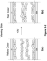
- the high positive particles are of a black color (K); the high negative particles are of a yellow color (Y); the low positive particles are of a red color (R); and the low negative particles are of a white color (W).
- the electric field generated by the low driving voltage is sufficient to separate the weaker charged white and red particles to cause the low positive red particles (R) to move all the way to the common electrode (21) side (i.e., the viewing side) and the low negative white particles (W) to move to the pixel electrode (22a) side.
- a red color is seen.
- weaker charged particles e.g., R
- stronger charged particles of opposite polarity e.g., Y
- these attraction forces are not as strong as the attraction force between two types of stronger charged particles (K and Y) and therefore they can be overcome by the electric field generated by the low driving voltage. In other words, weaker charged particles and the stronger charged particles of opposite polarity can be separated.
- the electric field generated by the low driving voltage is sufficient to separate the white and red particles to cause the low negative white particles (W) to move all the way to the common electrode side (i.e., the viewing side) and the low positive red particles (R) move to the pixel electrode side.
- W low negative white particles
- R low positive red particles
- a white color is seen.
- weaker charged particles e.g., W
- stronger charged particles of opposite polarity e.g., K
- these attraction forces are not as strong as the attraction force between two types of stronger charged particles (K and Y) and therefore they can be overcome by the electric field generated by the low driving voltage. In other words, weaker charged particles and the stronger charged particles of opposite polarity can be separated.
- the black particles (K) is demonstrated to carry a high positive charge
- the yellow particles (Y) to carry a high negative charge
- the red (R) particles to carry a low positive charge
- the white particles (W) to carry a low negative charge
- the particles carry a high positive charge, or a high negative charge, or a low positive charge or a low negative charge may be of any colors.
- the lower voltage potential difference applied to reach the color states in Figures 2(c) and 2(d) may be about 5% to about 50% of the full driving voltage potential difference required to drive the pixel from the color state of high positive particles to the color state of the high negative particles, or vice versa.
- the electrophoretic fluid as described above is filled in display cells.
- the display cells may be cup-like microcells as described in US Patent No. 6,930,818 .
- the display cells may also be other types of micro-containers, such as microcapsules, microchannels or equivalents, regardless of their shapes or sizes.
- a shaking waveform may be used.
- the shaking waveform consists of repeating a pair of opposite driving pulses for many cycles.
- the shaking waveform may consist of a +15V pulse for 20 msec and a -15V pulse for 20 msec and such a pair of pulses is repeated for 50 times.
- the total time of such a shaking waveform would be 2000 msec (see Figure 3 ).
- the shaking waveform may be applied regardless of the optical state (black, white, red or yellow) before a driving voltage is applied. After the shaking waveform is applied, the optical state would not be a pure white, pure black, pure yellow or pure red. Instead, the color state would be from a mixture of the four types of pigment particles.
- Each of the driving pulse in the shaking waveform is applied for not exceeding 50% (or not exceeding 30%, 10% or 5%) of the driving time required from the full black state to the full yellow state, or vice versa, in the example.
- the shaking waveform may consist of positive and negative pulses, each applied for not more than150 msec. In practice, it is preferred that the pulses are shorter.
- the shaking waveform is abbreviated (i.e., the number of pulses is fewer than the actual number).
- a high driving voltage (V H1 or V H2 ) is defined as a driving voltage which is sufficient to drive a pixel from the color state of high positive particles to the color state of high negative particles, or vice versa (see Figures 2a and 2b).
- a low driving voltage (V L1 or V L2 ) is defined as a driving voltage which may be sufficient to drive a pixel to the color state of weaker charged particles from the color state of higher charged particles (see Figures 2c and 2d).
- the amplitude of V L (e.g., V L1 or V L2 ) is less than 50%, or preferably less than 40%, of the amplitude of V H (e.g., V H1 or V H2 ).
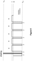
- FIG 4 illustrates a driving method to drive a pixel from a yellow color state (high negative) to a red color state (low positive).
- a high negative driving voltage V H2 , e.g., -15V
- V H2 high negative driving voltage
- a shaking waveform is then applied.
- the high negative voltage (V H2 ) is then again applied for a period t2.
- V L1 low positive voltage
- t3 that is, driving the pixel from Figure 2a to Figure 2c).
- the driving period t2 is a time period sufficient to drive a pixel to the yellow state when V H2 is applied and the driving period t3 (longer than t2) is a time period sufficient to drive the pixel to the red state from the yellow state when V L1 is applied.
- the application of the driving voltage for a period of t1 before the shaking waveform helps to ensure DC balance.
- the term "DC balance", throughout this application, is intended to mean that the driving voltages applied to a pixel is substantially zero when integrated over a period of time (e.g., the period of an entire waveform).
- FIG 5 illustrates a driving method to drive a pixel from a black color state (high positive) to a white color state (low negative).
- a high positive driving voltage V H1 , e.g., +15V
- V H1 a high positive driving voltage
- V H1 a low negative voltage
- t6 a low negative voltage
- the driving period t5 is a time period sufficient to drive a pixel to the black state when V H1 is applied and the driving period t6 (longer than t5) is a time period sufficient to drive the pixel to the white state from the black state when V L2 is applied.
- the application of the driving voltage for a period of t4 before the shaking waveform helps to ensure DC balance.
- the entire waveform of Figure 4 is DC balanced.
- the entire waveform of Figure 5 is also DC balanced.
- Figure 6 illustrates a partial driving waveform which may be used to replace the portion of the driving waveform of Figure 4 in period t3.
- the high negative driving voltage (V H2 , e.g., -15V) is applied for a period of t7 to push the yellow particles towards the viewing side, which is followed by a positive driving voltage (+V') for a period of t8, which pulls the yellow particles down and pushes the red particles towards the viewing side.
- the amplitude of +V' is lower than that of V H (e.g., V H1 or V H2 ). In one embodiment, the amplitude of the +V' is less than 50% of the amplitude of V H (e.g., V H1 or V H2 ).
- t8 is greater than t7. In one embodiment, t7 may be in the range of 20-400 msec and t8 may be ⁇ 200 msec.
- the waveform of Figure 6 is repeated for at least 2 cycles (N ⁇ 2), preferably at least 4 cycles and more preferably at least 8 cycles.
- the red color becomes more intense after each driving cycle.
- the driving waveform as shown in Figure 6 may be used to replace the driving period of t3 in Figure 4 (thus producing the overall waveform shown in Figure 7 ).
- the driving sequence may be: driving towards the yellow state for a period of t1, shaking waveform, followed by driving towards the yellow state for a period of t2 and then applying the waveform of Figure 6 .
- the step of driving to the yellow state for a period of t2 may be eliminated and in this case, a shaking waveform is applied before applying the waveform of Figure 6 (see Figure 8 - note that the shaking waveform is immediately followed by driving towards yellow for a period t7).
- the entire waveform of Figure 7 is DC balanced.
- the entire waveform of Figure 8 is also DC balanced.
- Figure 9 illustrates a partial driving waveform which may be used to replace the portion of the driving waveform of Figure 5 in period t6.
- a high positive driving voltage (V H1 , e.g., +15V) is applied, for a period of t9 to push the black particles towards the viewing side, which is followed by applying a negative driving voltage (-V') for a period of t10, which pulls the black particles down and pushes the white particles towards the viewing side.
- V H1 high positive driving voltage
- -V' negative driving voltage
- the amplitude of the -V' is lower than that of V H (e.g., V H1 or V H2 ). In one embodiment, the amplitude of -V' is less than 50% of the amplitude of V H (e.g., V H1 or V H2 ).
- t10 is greater than t9. In one embodiment, t9 may be in the range of 20-400 msec and t10 may be ⁇ 200 msec.
- the waveform of Figure 9 is repeated for at least 2 cycles (N ⁇ 2), preferably at least 4 cycles and more preferably at least 8 cycles.
- the white color becomes more intense after each driving cycle.
- the driving waveform as shown in Figure 9 may be used to replace the driving period of t6 in Figure 5 (thus producing the overall waveform shown in Figure 10 ).
- the driving sequence may be: driving towards the black state for a period t4, shaking waveform, followed by driving towards the black state for a period of t5 and then applying the waveform of Figure 9 .
- the step of driving to the black state for a period of t5 may be eliminated and in this case, a shaking waveform is applied before applying the waveform of Figure 9 (see Figure 11 - note that the shaking waveform is immediately followed by driving towards black for a period t9).
- the entire waveform of Figure 10 is DC balanced.
- the entire waveform of Figure 11 is also DC balanced.
- the amplitude of the second driving voltage is less than 50% of the amplitude of the first driving voltage. In one embodiment, steps (i) and (ii) are repeated at least 2 times, preferably at least 4 times and more preferably at least 8 times.
- Figure 12 illustrates a partial driving waveform which may be used as an alternative to the partial driving waveform of Figure 6 to replace the portion of the driving waveform of Figure 4 in period t3.
- the partial waveform of Figure 12 differs from that of Figure 6 by the addition of a wait time t13. During the wait time, no driving voltage is applied.
- the entire waveform of Figure 12 is also repeated at least 2 times (N ⁇ 2), preferably at least 4 times and more preferably at least 8 times.
- the waveform of Figure 12 is designed to release the charge imbalance stored in the dielectric layers and/or at the interfaces between layers of different materials, in an electrophoretic display device, especially when the resistance of the dielectric layers is high, for example, at a low temperature.
- low temperature refers to a temperature below about 10oC.
- the wait time presumably can dissipate the unwanted charge stored in the dielectric layers and cause the short pulse (t11) for driving a pixel towards the yellow state and the longer pulse (t12) for driving the pixel towards the red state to be more efficient.
- this alternative driving method will bring a better separation of the low charged pigment particles from the higher charged ones.
- the time periods, t11 and t12 are similar to t7 and t8 in Figure 6 , respectively. In other words, t12 is greater than t11.
- the wait time (t13) can be in a range of 5-5,000 msec, depending on the resistance of the dielectric layers.
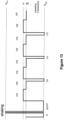
- the driving waveform shown in Figure 12 may be used to replace the driving period of t3 in Figure 4 (thus producing the overall waveform shown in Figure 13 ).
- the driving sequence may be: driving towards the yellow state for a period of t1, shaking waveform, followed by driving towards the yellow state for a period of t2 and then applying the waveform of Figure 12 .
- the step of driving to the yellow state for a period of t2 may be eliminated and in this case, a shaking waveform is applied before applying the waveform of Figure 12 (see Figure 14 ).
- the entire waveform of Figure 13 is DC balanced.
- the entire waveform of Figure 14 is also DC balanced.
- Figure 15 illustrates a partial driving waveform which may be used as an alternative to the driving waveform of Figure 9 to replace the portion of the driving waveform of Figure 5 in period t6.
- the partial waveform of Figure 15 differs from that of Figure 9 by the addition of a wait time t16. During the wait time, no driving voltage is applied.
- the entire waveform of Figure 15 is also repeated at least 2 times (N ⁇ 2), preferably at least 4 times and more preferably at least 8 times.
- the waveform of Figure 15 is designed to release the charge imbalance stored in the dielectric layers and/or at the interfaces of layers of different materials, in an electrophoretic display device.
- the wait time presumably can dissipate the unwanted charge stored in the dielectric layers and cause the short pulse (t14) for driving a pixel towards the black state and the longer pulse (t15) for driving the pixel towards the white state to be more efficient.
- the time periods, t14 and t15 are similar to t9 and t10 in Figure 9 , respectively. In other words, t15 is greater than t14.
- the wait time (t16) may also be in a range of 5-5,000 msec, depending on the resistance of the dielectric layers.
- the driving waveform shown in Figure 15 may be used to replace the driving period of t6 in Figure 5 (thus producing the overall waveform shown in Figure 16 ).
- the driving sequence may be: driving towards black state for a period of t4, shaking waveform, followed by driving towards the black state for a period of t5 and then applying the waveform of Figure 15 .
- the step of driving to the black state for a period of t5 may be eliminated and in this case, a shaking waveform is applied before applying the waveform of Figure 15 (see Figure 17 ).
- the entire waveform of Figure 16 is DC balanced.
- the entire waveform of Figure 17 is also DC balanced.
- the amplitude of the second driving voltage is less than 50% of the amplitude of the first driving voltage. In one embodiment, steps (i), (ii) and (iii) are repeated at least 2 times, preferably at least 4 times and more preferably at least 8 times.
- any of the driving periods referred to in this application may be temperature dependent.
- Figure 18 illustrates a partial driving waveform which may be used as an alternative to the partial driving waveforms of Figure 6 or 12 to replace the portion of the driving waveform of Figure 4 in period t3.
- a high negative driving voltage (V H2 , e.g., -15V) is applied to a pixel for a period of t17, which is followed by a wait time of t18.
- a positive driving voltage (+V', e.g., less than 50% of V H1 or V H2 ) is applied to the pixel for a period of t19, which is followed by a second wait time of t20.
- the waveform of Figure 18 is repeated at least 2 times, preferably at least 4 times and more preferably at least 8 times.
- wait time refers to a period of time in which no driving voltage is applied.
- the first wait time t18 is very short while the second wait time t20 is longer.
- the period of t17 is also shorter than the period of t19.
- t17 may be in the range of 20-200 msec; t18 may be less than 100 msec; t19 may be in the range of 100-200 msec; and t20 may be less than 1000 msec.
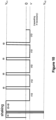
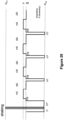
- Figure 19 shows the overall waveform resulting from inserting the partial waveform of Figure 18 in place of period t3 in the waveform of Figure 4 .
- a yellow state is displayed during the period t2.
- the better the yellow state in this period the better the red state that will be displayed at the end.
- the entire waveform of Figure 19 is DC balanced.
- the entire waveform of Figure 20 is also DC balanced.
- Figure 21 illustrates a partial driving waveform which may be used as an alternative to the partial driving waveforms of Figure 9 or 15 to replace the portion of the driving waveform of Figure 5 in period t6.
- a high positive driving voltage (V H1 , e.g., +15V) is applied to a pixel for a period of t21, which is followed by a wait time of t22.
- a negative driving voltage (-V', e.g., less than 50% of V H1 or V H2 ) is applied to the pixel for a period of t23, which is followed by a second wait time of t24.
- the waveform of Figure 21 may also be repeated at least 2 times, preferably at least 4 times and more preferably at least 8 times.
- the first wait time t22 is very short while the second wait time t24 is longer.
- the period of t21 is also shorter than the period of t23.
- t21 may be in the range of 20-200 msec; t22 may be less than 100 msec; t23 may be in the range of 100-200 msec; and t24 may be less than 1000 msec.
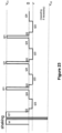
- Figure 22 shows the overall waveform resulting from inserting the partial waveform of Figure 21 in place of period t6 in the waveform of Figure 5 .
- a black state is displayed during the period t5.
- the better the black state in this period the better the white state that will be displayed at the end.
- the entire waveform of Figure 22 is DC balanced.
- the entire waveform of Figure 23 is also DC balanced.
- the amplitude of the second driving voltage is less than 50% of the amplitude of the first driving voltage. In one embodiment, steps (i)-(iv) are repeated at least 2 times, preferably at least 4 times and more preferably at least 8 times.
- This driving method not only is particularly effective at a low temperature, it can also provide a display device better tolerance of structural variations caused during manufacture of the display device. Therefore its usefulness is not limited to low temperature driving.
- the driving method shown in Figures 24-26 is particularly suitable for low temperature driving of a pixel from the yellow state (high negative) to the red state (low positive).
- a low negative driving voltage (-V') is first applied for a time period of t25, followed by a low positive driving voltage (+V") for a time period of t26. Since the sequence is repeated, there is also a wait time of t27 between the two driving voltages.
- Such a waveform may be repeated at least 2 times (N' ⁇ 2), preferably at least 4 times and more preferably at least 8 times.
- the time period of t25 is shorter than the time period of t26.
- the time period of t27 may be in the range of 0 to 200 msec.
- the amplitudes of the driving voltages, V' and V" may be 50% of the amplitude of V H (e.g., V H1 or V H2 ). It is also noted that the amplitude of V' may be the same as, or different from, the amplitude of V".
- the entire waveform of Figure 25 is DC balanced.
- the entire waveform of Figure 26 is also DC balanced.
- the driving method shown in Figures 27-29 is particularly suitable for low temperature driving of a pixel from the black state (high positive) to the white state (low negative).
- a low positive driving voltage (+V') is first applied for a time period of t28, followed by a low negative driving voltage (-V") for a time period of t29. Since this sequence is repeated, there is also a wait time of t30 between the two driving voltages.
- Such a waveform may be repeated at least 2 times (e.g., N' ⁇ 2), preferably at least 4 times and more preferably as least 8 times.
- the time period of t28 is shorter than the time period of t29.
- the time period of t30 may be in the range of 0 to 200 msec.
- the amplitudes of the driving voltages, V' and V" may be 50% of the amplitude of V H (e.g., V H1 or V H2 ). It is also noted that the amplitude of V' may be the same as, or different from, the amplitude of V".
- the entire waveform of Figure 28 is DC balanced.
- the entire waveform of Figure 29 is also DC balanced.
- steps (v)-(vii) are repeated at least 2 times, preferably at least 4 times and more preferably at least 8 times.
Landscapes
- Engineering & Computer Science (AREA)
- Physics & Mathematics (AREA)
- Computer Hardware Design (AREA)
- General Physics & Mathematics (AREA)
- Theoretical Computer Science (AREA)
- Control Of Indicators Other Than Cathode Ray Tubes (AREA)
- Electrochromic Elements, Electrophoresis, Or Variable Reflection Or Absorption Elements (AREA)
- Liquid Crystal (AREA)
- Devices For Indicating Variable Information By Combining Individual Elements (AREA)
Claims (12)
- Ansteuerungsverfahren zum Ansteuern einer elektrophoretischen Anzeige, die eine erste Oberfläche (13) auf einer Sichtseite, eine zweite Oberfläche (14) auf einer Nicht-Sichtseite und ein elektrophoretisches Fluid umfasst, wobei das Fluid zwischen einer gemeinsamen Elektrode (11; 21), die auf der ersten Oberfläche angeordnet ist, und einer Schicht Pixelelektroden (12a; 22) eingefasst ist, die auf der zweiten Oberfläche angeordnet sind, wobei das Fluid einen ersten Partikeltyp (K), einen zweiten Partikeltyp (Y), einen dritten Partikeltyp (R) und einen vierten Partikeltyp (W) umfasst, die alle in einem Lösemittel oder einer Lösemittelmischung dispergiert sind, wobei(a) die vier Pigmentpartikeltypen (K, Y, R, W) optische Eigenschaften aufweisen, die sich voneinander unterscheiden;(b) der erste Partikeltyp (K) eine hochpositive Ladung trägt und der zweite Partikeltyp (Y) eine hochnegative Ladung trägt; und(c) der dritte Partikeltyp (R) eine niedrigpositive Ladung trägt und der vierte Partikeltyp (W) eine niedrignegative Ladung trägt, das Verfahren die folgenden Schritte umfassend:(i) Anlegen einer ersten Ansteuerungsspannung (VH1) zwischen der Pixelelektrode (12a; 22) und der gemeinsamen Elektrode (11; 21) eines Pixels in der elektrophoretischen Anzeige für eine erste Zeitdauer (t4, t5), um den ersten Partikeltyp (K) in Richtung auf die gemeinsame Elektrode (11, 21) und den zweiten Partikeltyp (Y) in Richtung auf die Pixelelektrode (12a; 22) anzusteuern und dadurch den Pixel auf der Sichtseite in Richtung auf den Farbzustand des ersten Partikeltyps (K) anzusteuern; und(ii) Anlegen einer zweiten Ansteuerungsspannung (VL2) zwischen der Pixelelektrode (12a; 22) und der gemeinsamen Elektrode (11; 21) des Pixels für eine zweite Zeitdauer (t6), wobei die zweite Ansteuerungsspannung (VL2) eine Polarität, die derjenigen der ersten Ansteuerungsspannung (VH1) entgegengesetzt ist, und eine Amplitude aufweist, die geringer ist als diejenige der ersten Ansteuerungsspannung (VH1), um den vierten Partikeltyp (W) in Richtung auf die gemeinsame Elektrode (11; 21) und den dritten Partikeltyp (R) in Richtung auf die Pixelelektrode (12a; 22) anzusteuern, während der erste (K) und der zweite (Y) Partikeltyp sowohl von der gemeinsamen Elektrode (11; 21) als auch von der Pixelelektrode (12a; 22) beabstandet zurückbleiben, und dadurch den Pixel auf der Sichtseite aus dem Farbzustand des ersten Partikeltyps (K) in Richtung auf den Farbzustand des vierten Partikeltyps (W) anzusteuern,wobei das Verfahren dadurch gekennzeichnet ist, dass Schritt (i) bewirkt wird durch:(i) (a) Anlegen der ersten Ansteuerungsspannung (VH1) für eine dritte Zeitdauer (t4);(i)(b) Anlegen einer Schüttelwellenform; und(i)(c) Anlegen der ersten Ansteuerungsspannung (VH1) für eine vierte Zeitdauer (t5),wobei die zweite Zeitdauer (t6) größer ist als die vierte Zeitdauer (t5).
- Ansteuerungsverfahren zum Ansteuern einer elektrophoretischen Anzeige, die eine erste Oberfläche (13) auf einer Sichtseite, eine zweite Oberfläche (14) auf einer Nicht-Sichtseite und ein elektrophoretisches Fluid umfasst, wobei das Fluid zwischen einer gemeinsamen Elektrode (11; 21), die auf der ersten Oberfläche angeordnet ist, und einer Schicht Pixelelektroden (12a; 22) eingefasst ist, die auf der zweiten Oberfläche angeordnet sind, wobei das Fluid einen ersten Partikeltyp (K), einen zweiten Partikeltyp (Y), einen dritten Partikeltyp (R) und einen vierten Partikeltyp (W) umfasst, die alle in einem Lösemittel oder einer Lösemittelmischung dispergiert sind, wobei(a) die vier Pigmentpartikeltypen (K, Y, R, W) optische Eigenschaften aufweisen, die sich voneinander unterscheiden;(b) der erste Partikeltyp (K) eine hochpositive Ladung trägt und der zweite Partikeltyp (Y) eine hochnegative Ladung trägt; und(c) der dritte Partikeltyp (R) eine niedrigpositive Ladung trägt und der vierte Partikeltyp (W) eine niedrignegative Ladung trägt,das Verfahren die folgenden Schritte umfassend:(i) Anlegen einer ersten Ansteuerungsspannung (VH2) zwischen der Pixelelektrode (12a; 22) und der gemeinsamen Elektrode (11; 21) eines Pixels in der elektrophoretischen Anzeige für eine erste Zeitdauer (t1, t2), um den zweiten Partikeltyp (Y) in Richtung auf die gemeinsame Elektrode (11; 21) und den ersten Partikeltyp (K) in Richtung auf die Pixelelektrode (12a; 22) anzusteuern und dadurch den Pixel auf der Sichtseite in Richtung auf den Farbzustand des zweiten Partikeltyps (Y) anzusteuern; und(ii) Anlegen einer zweiten Ansteuerungsspannung (VL1) zwischen der Pixelelektrode (12a; 22) und der gemeinsamen Elektrode (11; 21) des Pixels für eine zweite Zeitdauer (t3), wobei die zweite Ansteuerungsspannung (VL1) eine Polarität, die derjenigen der ersten Ansteuerungsspannung (VH2) entgegengesetzt ist, und eine Amplitude aufweist, die geringer ist als diejenige der ersten Ansteuerungsspannung (VH2), um den dritten Partikeltyp (R) in Richtung auf die gemeinsame Elektrode (11; 21) und den vierten Partikeltyp (W) in Richtung auf die Pixelelektrode (12a; 22) anzusteuern, während der erste (K) und der zweite (Y) Partikeltyp sowohl von der gemeinsamen Elektrode (11; 21) als auch von der Pixelelektrode (12a; 22) beabstandet zurückbleiben, und dadurch den Pixel auf der Sichtseite aus dem Farbzustand des zweiten Partikeltyps (Y) in Richtung auf den Farbzustand des dritten Partikeltyps (R) anzusteuern,wobei das Verfahren dadurch gekennzeichnet ist, dass Schritt (i) bewirkt wird durch:(i)(a) Anlegen der ersten Ansteuerungsspannung (VH2) für eine dritte Zeitdauer (t1);(i)(b) Anlegen einer Schüttelwellenform; und(i)(c) Anlegen der ersten Ansteuerungsspannung (VH2) für eine vierte Zeitdauer (t2), wobei die zweite Zeitdauer (t3) größer ist als die vierte Zeitdauer (t2).
- Ansteuerungsverfahren nach Anspruch 1 oder 2, wobei die zweite Zeitdauer (t3; t6) größer ist als die erste Zeitdauer (t1, t2; t4, t5) und die Schritte (i) und (ii) wiederholt werden.
- Ansteuerungsverfahren nach Anspruch 3, weiterhin Folgendes umfassend(iii) nach Schritt (ii), aber vor der Wiederholung von Schritt (i), Anlegen keiner Ansteuerungsspannung zwischen der Pixelelektrode (12a; 22) und der gemeinsamen Elektrode (11; 21) des Pixels für eine fünfte Zeitdauer (t13; t16); undwobei die Schritte (i) bis (iii) wiederholt werden.
- Ansteuerungsverfahren nach Anspruch 3, weiterhin Folgendes umfassend(iii) nach Schritt (i), aber vor Schritt (ii), Anlegen keiner Ansteuerungsspannung zwischen der Pixelelektrode (12a; 22) und der gemeinsamen Elektrode (11; 21) des Pixels für eine sechste Zeitdauer (t18; t22) ;(iv) nach Schritt (ii), aber vor der Wiederholung von Schritt (i), Anlegen keiner Ansteuerungsspannung zwischen der Pixelelektrode (12a; 22) und der gemeinsamen Elektrode (11; 21) des Pixels für eine siebte Zeitdauer (t20; t24); undwobei die Schritte (i) bis (iv) wiederholt werden.
- Verfahren nach Anspruch 3, 4 oder 5, wobei die Amplitude der zweiten Ansteuerungsspannung (VL1; VL2) kleiner ist als 50 % der Amplitude der ersten Ansteuerungsspannung (VH1; VH2).
- Verfahren nach Anspruch 3, 4 oder 5, wobei die Schritte (i), (ii), (iii) (wenn vorhanden) und (iv) (wenn vorhanden) mindestens 4 Mal wiederholt werden.
- Verfahren nach Anspruch 7, wobei die Schritte mindestens 8 Mal wiederholt werden.
- Ansteuerungsverfahren nach Anspruch 5, weiterhin die folgenden Schritte umfassend:(v) Anlegen einer dritten Ansteuerungsspannung (V'; V") zwischen der Pixelelektrode (12a; 22) und der gemeinsamen Elektrode (11; 21) des Pixels für eine siebte Zeitdauer (t25; t28), wobei die dritte Ansteuerungsspannung (V'; V") die gleiche Polarität aufweist wie die erste Ansteuerungsspannung (VH2; VH1);(vi) Anlegen einer vierten Ansteuerungsspannung (V"; V') zwischen der Pixelelektrode (12a; 22) und der gemeinsamen Elektrode (11; 21) des Pixels für eine achte Zeitdauer (t26; t29), wobei die siebte Zeitdauer (t25; t28) kürzer ist als die achte Zeitdauer (t26; t29) und die vierte Ansteuerungsspannung (V"; V') eine Polarität aufweist, die derjenigen der ersten Ansteuerungsspannung (VH2; VH1) entgegengesetzt ist, um den Pixel auf der Sichtseite aus dem Farbzustand des ersten Partikeltyps (K) in Richtung auf den Farbzustand des vierten Partikeltyps (W) oder aus dem Farbzustand des zweiten Partikeltyps (Y) in Richtung auf den Farbzustand des dritten Partikeltyps (R) anzusteuern;(vii) Anlegen keiner Ansteuerungsspannung zwischen der Pixelelektrode (12a; 22) und der gemeinsamen Elektrode (11; 21) des Pixels für eine neunte Zeitdauer (t27; t30); und Wiederholen der Schritte (v) bis (vii).
- Verfahren nach Anspruch 9, wobei die Amplituden sowohl der dritten Ansteuerungsspannung (V'; V") als auch der vierten Ansteuerungsspannung (V"; V') kleiner sind als 50 % der Amplitude der ersten Ansteuerungsspannung (VH2; VH1).
- Verfahren nach Anspruch 9, wobei die Schritte (v) bis (vii) mindestens 4 Mal wiederholt werden.
- Verfahren nach Anspruch 11, wobei die Schritte (v) bis (vii) mindestens 8 Mal wiederholt werden.
Applications Claiming Priority (2)
| Application Number | Priority Date | Filing Date | Title |
|---|---|---|---|
| US201462080845P | 2014-11-17 | 2014-11-17 | |
| PCT/US2015/060178 WO2016081243A1 (en) | 2014-11-17 | 2015-11-11 | Color display device |
Publications (4)
| Publication Number | Publication Date |
|---|---|
| EP3221744A1 EP3221744A1 (de) | 2017-09-27 |
| EP3221744A4 EP3221744A4 (de) | 2018-04-18 |
| EP3221744C0 EP3221744C0 (de) | 2023-06-07 |
| EP3221744B1 true EP3221744B1 (de) | 2023-06-07 |
Family
ID=55962233
Family Applications (1)
| Application Number | Title | Priority Date | Filing Date |
|---|---|---|---|
| EP15860337.3A Active EP3221744B1 (de) | 2014-11-17 | 2015-11-11 | Farbanzeigevorrichtung |
Country Status (10)
| Country | Link |
|---|---|
| US (1) | US9812073B2 (de) |
| EP (1) | EP3221744B1 (de) |
| JP (4) | JP2017535820A (de) |
| KR (2) | KR102100601B1 (de) |
| CN (2) | CN107003583B (de) |
| CA (1) | CA2967038C (de) |
| ES (1) | ES2946784T3 (de) |
| PL (1) | PL3221744T3 (de) |
| TW (1) | TWI592729B (de) |
| WO (1) | WO2016081243A1 (de) |
Cited By (1)
| Publication number | Priority date | Publication date | Assignee | Title |
|---|---|---|---|---|
| WO2025136583A1 (en) * | 2023-12-20 | 2025-06-26 | E Ink Corporation | Driving sequences for multi-particle electrophoretic displays providing improved color states |
Families Citing this family (89)
| Publication number | Priority date | Publication date | Assignee | Title |
|---|---|---|---|---|
| US9360733B2 (en) | 2012-10-02 | 2016-06-07 | E Ink California, Llc | Color display device |
| US11017705B2 (en) | 2012-10-02 | 2021-05-25 | E Ink California, Llc | Color display device including multiple pixels for driving three-particle electrophoretic media |
| US9501981B2 (en) | 2013-05-17 | 2016-11-22 | E Ink California, Llc | Driving methods for color display devices |
| US10726760B2 (en) | 2013-10-07 | 2020-07-28 | E Ink California, Llc | Driving methods to produce a mixed color state for an electrophoretic display |
| TWI550332B (zh) | 2013-10-07 | 2016-09-21 | 電子墨水加利福尼亞有限責任公司 | 用於彩色顯示裝置的驅動方法 |
| US10380931B2 (en) | 2013-10-07 | 2019-08-13 | E Ink California, Llc | Driving methods for color display device |
| PL3095007T3 (pl) | 2014-01-14 | 2020-10-05 | E Ink California, Llc | Sposób sterowania warstwą wyświetlacza kolorowego |
| US20150268531A1 (en) | 2014-03-18 | 2015-09-24 | Sipix Imaging, Inc. | Color display device |
| US9922603B2 (en) | 2014-07-09 | 2018-03-20 | E Ink California, Llc | Color display device and driving methods therefor |
| US10891906B2 (en) | 2014-07-09 | 2021-01-12 | E Ink California, Llc | Color display device and driving methods therefor |
| ES2919787T3 (es) | 2014-07-09 | 2022-07-28 | E Ink California Llc | Procedimiento de excitación de un dispositivo de visualización electroforético en color |
| US10380955B2 (en) | 2014-07-09 | 2019-08-13 | E Ink California, Llc | Color display device and driving methods therefor |
| US10147366B2 (en) | 2014-11-17 | 2018-12-04 | E Ink California, Llc | Methods for driving four particle electrophoretic display |
| US9640119B2 (en) | 2014-11-17 | 2017-05-02 | E Ink California, Llc | Driving methods for color display devices |
| EP3221744B1 (de) * | 2014-11-17 | 2023-06-07 | E Ink California, LLC | Farbanzeigevorrichtung |
| CN115019719B (zh) | 2015-04-06 | 2025-02-25 | 伊英克公司 | 彩色显示装置的驱动方法 |
| CN107683436B (zh) | 2015-06-01 | 2021-06-25 | 伊英克加利福尼亚有限责任公司 | 彩色显示装置及其驱动方法 |
| US11087644B2 (en) | 2015-08-19 | 2021-08-10 | E Ink Corporation | Displays intended for use in architectural applications |
| US10062337B2 (en) | 2015-10-12 | 2018-08-28 | E Ink California, Llc | Electrophoretic display device |
| US10276109B2 (en) | 2016-03-09 | 2019-04-30 | E Ink Corporation | Method for driving electro-optic displays |
| US10593272B2 (en) | 2016-03-09 | 2020-03-17 | E Ink Corporation | Drivers providing DC-balanced refresh sequences for color electrophoretic displays |
| PT3465628T (pt) | 2016-05-24 | 2020-07-24 | E Ink Corp | Método para reprodução de imagens de cor |
| JP7139335B2 (ja) | 2017-01-20 | 2022-09-20 | イー インク カリフォルニア, エルエルシー | 着色有機顔料およびこれを含む電気泳動ディスプレイ媒体 |
| CA3200340A1 (en) | 2017-03-06 | 2018-09-13 | E Ink Corporation | Method and apparatus for rendering color images |
| CN110366747B (zh) * | 2017-04-25 | 2022-10-18 | 伊英克加利福尼亚有限责任公司 | 用于彩色显示设备的驱动方法 |
| CN106909011B (zh) * | 2017-05-10 | 2020-06-05 | 上海天马微电子有限公司 | 一种电子纸显示面板、驱动方法及电子纸显示装置 |
| CN107633819B (zh) * | 2017-08-08 | 2019-12-03 | 江西兴泰科技有限公司 | 一种三色电子纸模组的驱动波形调试方法 |
| CN107342057A (zh) | 2017-08-09 | 2017-11-10 | 京东方科技集团股份有限公司 | 用于驱动电泳显示面板的方法、装置以及显示装置 |
| KR102373214B1 (ko) * | 2017-10-04 | 2022-03-10 | 이 잉크 캘리포니아 엘엘씨 | 4-입자 전기영동 디스플레이를 구동하는 방법 |
| US11266832B2 (en) | 2017-11-14 | 2022-03-08 | E Ink California, Llc | Electrophoretic active delivery system including porous conductive electrode layer |
| JP7148324B2 (ja) * | 2017-12-11 | 2022-10-05 | Tianma Japan株式会社 | 光線方向制御装置及び光線方向制御素子の駆動方法 |
| US11079651B2 (en) | 2017-12-15 | 2021-08-03 | E Ink Corporation | Multi-color electro-optic media |
| CN111492307A (zh) | 2017-12-19 | 2020-08-04 | 伊英克公司 | 电光显示器的应用 |
| US11248122B2 (en) | 2017-12-30 | 2022-02-15 | E Ink Corporation | Pigments for electrophoretic displays |
| US11143929B2 (en) | 2018-03-09 | 2021-10-12 | E Ink Corporation | Reflective electrophoretic displays including photo-luminescent material and color filter arrays |
| WO2020018508A1 (en) * | 2018-07-17 | 2020-01-23 | E Ink California, Llc | Electro-optic displays and driving methods |
| EP3888079A4 (de) * | 2018-11-30 | 2022-08-24 | E Ink California, LLC | Elektro-optische anzeigen und ansteuerungsverfahren |
| JP7335356B2 (ja) | 2019-05-07 | 2023-08-29 | イー インク コーポレイション | 可変光透過デバイスのための駆動方法 |
| KR102797900B1 (ko) | 2019-11-27 | 2025-04-21 | 이 잉크 코포레이션 | 전기 침식 밀봉층을 갖는 마이크로셀들을 포함하는 유익제 전달 시스템 |
| CN111402818A (zh) * | 2020-03-31 | 2020-07-10 | 重庆京东方智慧电子系统有限公司 | 彩色电子纸的驱动方法及彩色电子纸 |
| KR102815310B1 (ko) * | 2020-06-05 | 2025-05-30 | 이 잉크 코포레이션 | 적어도 4개 타입들의 입자들을 포함하는 전기영동 매체에서 적게 하전된 입자들의 컬러 상태들을 달성하기 위한 방법들 |
| KR102748422B1 (ko) | 2020-06-05 | 2024-12-30 | 이 잉크 코포레이션 | 전기영동 디스플레이 디바이스 |
| EP4214574A4 (de) | 2020-09-15 | 2024-10-09 | E Ink Corporation | Elektrophoretisches vierpartikelmedium mit schneller kontrastreicher optischer zustandsumschaltung |
| KR20250048119A (ko) | 2020-09-15 | 2025-04-07 | 이 잉크 코포레이션 | 진보된 컬러 전기영동 디스플레이를 위한 개선된 구동 전압 및 개선된 구동 전압에 의한 디스플레이 |
| US12181767B2 (en) | 2020-09-15 | 2024-12-31 | E Ink Corporation | Five-particle electrophoretic medium with improved black optical state |
| US11846863B2 (en) | 2020-09-15 | 2023-12-19 | E Ink Corporation | Coordinated top electrode—drive electrode voltages for switching optical state of electrophoretic displays using positive and negative voltages of different magnitudes |
| KR102921118B1 (ko) | 2020-11-02 | 2026-01-30 | 이 잉크 코포레이션 | 멀티 컬러 전기 영동 디스플레이들에서 원색 컬러 세트들을 달성하기 위한 향상된 푸시-풀(epp) 파형들 |
| CN116368553B (zh) * | 2020-11-02 | 2026-02-13 | 伊英克公司 | 从彩色电泳显示器中去除先前状态信息的驱动序列 |
| KR102636771B1 (ko) | 2020-11-02 | 2024-02-14 | 이 잉크 코포레이션 | 컬러 이미지들을 렌더링하기 위한 방법 및 장치 |
| KR102951575B1 (ko) | 2021-02-09 | 2026-04-10 | 이 잉크 코포레이션 | 멀티 컬러 전기영동 디스플레이들에서의 연속 파형 구동 |
| JP7688154B2 (ja) | 2021-04-16 | 2025-06-03 | イー インク コーポレイション | 薄型縁シールを伴う電気泳動ディスプレイ |
| AU2022266617B2 (en) | 2021-04-29 | 2024-08-01 | E Ink Corporation | Disaggregation driving sequences for four particle electrophoretic displays |
| KR102847961B1 (ko) * | 2021-05-25 | 2025-08-19 | 이 잉크 코포레이션 | 4개 입자 전기영동 디스플레이들을 위한 동기화된 구동 파형들 |
| CA3228148A1 (en) | 2021-09-06 | 2023-03-09 | E Ink Corporation | Method for driving electrophoretic display device |
| WO2023043714A1 (en) | 2021-09-14 | 2023-03-23 | E Ink Corporation | Coordinated top electrode - drive electrode voltages for switching optical state of electrophoretic displays using positive and negative voltages of different magnitudes |
| JP7724375B2 (ja) | 2021-11-05 | 2025-08-15 | イー インク コーポレイション | 低ブルーミング感度を伴う多原色ディスプレイマスクベースのディザリング |
| WO2023121901A1 (en) | 2021-12-22 | 2023-06-29 | E Ink Corporation | High voltage driving using top plane switching with zero voltage frames between driving frames |
| CN118451364A (zh) | 2022-01-04 | 2024-08-06 | 伊英克公司 | 包括电泳粒子和电荷控制剂组合的电泳介质 |
| US11984088B2 (en) | 2022-04-27 | 2024-05-14 | E Ink Corporation | Color displays configured to convert RGB image data for display on advanced color electronic paper |
| EP4578003A1 (de) | 2022-08-25 | 2025-07-02 | E Ink Corporation | Übergangsansteuermodi zum impulsausgleich beim umschalten zwischen globalem farbmodus und direktem aktualisierungsmodus für elektrophoretische anzeigen |
| KR102578744B1 (ko) * | 2022-09-23 | 2023-09-14 | 엔스펙트라 주식회사 | 반사형 맞춤 컬러 표시장치 |
| US20240402562A1 (en) | 2023-06-05 | 2024-12-05 | E Ink Corporation | Color electrophoretic medium having four pigment particle system addressable by waveforms having four voltage levels |
| US12406631B2 (en) | 2023-06-27 | 2025-09-02 | E Ink Corporation | Multi-particle electrophoretic display having low-flash image updates |
| US12412538B2 (en) | 2023-06-27 | 2025-09-09 | E Ink Corporation | Electrophoretic device with ambient light sensor and adaptive whiteness restoring and color balancing frontlight |
| AU2024307676A1 (en) | 2023-06-27 | 2025-09-04 | E Ink Corporation | Time-shifted waveforms for multi-particle electrophoretic displays providing low-flash image updates |
| US20250053058A1 (en) | 2023-08-08 | 2025-02-13 | E Ink Corporation | Backplanes for segmented electro-optic displays and methods of manufacturing same |
| US20250060333A1 (en) | 2023-08-16 | 2025-02-20 | E Ink Corporation | Devices, methods, and systems for visualizing electrowetting pathing using electrophoretic materials |
| US12456436B2 (en) | 2023-10-05 | 2025-10-28 | E Ink Corporation | Staged gate voltage control |
| US20250116908A1 (en) | 2023-10-06 | 2025-04-10 | E Ink Corporation | Large-area electro-optic light modulator or display |
| US20250138382A1 (en) | 2023-10-31 | 2025-05-01 | E Ink Corporation | Reflective display and projected capacitive touch sensor with shared transparent electrode |
| CN121909423A (zh) | 2023-11-08 | 2026-04-21 | 伊英克公司 | 用于生产电光显示器与光调制薄膜中使用的无缝微结构的连续光刻制造方法 |
| US20250201206A1 (en) | 2023-12-15 | 2025-06-19 | E Ink Corporation | Fast response color waveforms for multiparticle electrophoretic displays |
| WO2025136446A1 (en) | 2023-12-22 | 2025-06-26 | E Ink Corporation | Five-particle electrophoretic medium with improved black optical state |
| WO2025147410A2 (en) | 2024-01-02 | 2025-07-10 | E Ink Corporation | Electrophoretic media comprising a cationic charge control agent |
| US20250224645A1 (en) | 2024-01-05 | 2025-07-10 | E Ink Corporation | Electrophoretic medium comprising particles having a pigment core and a polymeric shell |
| US20250224646A1 (en) | 2024-01-08 | 2025-07-10 | E Ink Corporation | Adhesive Layer Comprising Conductive Filler Particles and a Polymeric Dispersant |
| US20250237922A1 (en) | 2024-01-19 | 2025-07-24 | E Ink Corporation | Flexible segmented electro-optic displays and methods of manufacture |
| WO2025155697A1 (en) | 2024-01-20 | 2025-07-24 | E Ink Corporation | Methods for delivering low-ghosting partial updates in color electrophoretic displays |
| TW202544785A (zh) | 2024-01-24 | 2025-11-16 | 美商電子墨水股份有限公司 | 產生低顆粒度全彩電子紙影像的改良方法 |
| WO2025198932A1 (en) | 2024-03-19 | 2025-09-25 | E Ink Corporation | Methods and systems for managing remnant voltage during fast updates in electrophoretic displays |
| US20250322811A1 (en) | 2024-04-11 | 2025-10-16 | E Ink Corporation | Driving sequences for reducing image ghosting in multi-particle electrophoretic displays |
| WO2025230802A1 (en) | 2024-04-30 | 2025-11-06 | E Ink Corporation | A variable light transmission device comprising microcells |
| US20250370306A1 (en) | 2024-05-30 | 2025-12-04 | E Ink Corporation | Chemically-Resistant Multi-Layered Electro-Optic Device and a Method of Making the Same |
| WO2025260003A1 (en) | 2024-06-13 | 2025-12-18 | E Ink Corporation | Microcells for electrophoretic displays and methods of preparing the same |
| WO2026006119A1 (en) | 2024-06-26 | 2026-01-02 | E Ink Corporation | A variable light transmission device comprising microcells |
| US20260003243A1 (en) | 2024-06-26 | 2026-01-01 | E Ink Corporation | Variable light transmission device comprising microcells |
| WO2026006117A1 (en) | 2024-06-26 | 2026-01-02 | E Ink Corporation | A variable light transmission device comprising microcells |
| US20260002057A1 (en) | 2024-07-01 | 2026-01-01 | E Ink Corporation | Photocurable resin for pressure-sensitive, anisotopically-conductive adhesives and methods of making and using the same |
| WO2026055042A1 (en) | 2024-09-03 | 2026-03-12 | E Ink Corporation | Methods for removing color shifts after electrophoretic display updates |
Citations (4)
| Publication number | Priority date | Publication date | Assignee | Title |
|---|---|---|---|---|
| US20070075963A1 (en) * | 2003-11-17 | 2007-04-05 | Guofu Zhou | Bi-stable display with dc-balanced over-reset driving |
| US20110298835A1 (en) * | 2010-06-07 | 2011-12-08 | Fuji Xerox Co., Ltd. | Display medium driving device, driving method, driving program storage medium, and display device |
| US20140092465A1 (en) * | 2012-10-02 | 2014-04-03 | Sipix Imaging, Inc. | Color display device |
| EP3167337B1 (de) * | 2014-07-09 | 2022-04-06 | E Ink California, LLC | Verfahren zur ansteuerung einer elektrophoretischen farbanzeigevorrichtung |
Family Cites Families (37)
| Publication number | Priority date | Publication date | Assignee | Title |
|---|---|---|---|---|
| US7038655B2 (en) | 1999-05-03 | 2006-05-02 | E Ink Corporation | Electrophoretic ink composed of particles with field dependent mobilities |
| JP4385438B2 (ja) | 1999-05-14 | 2009-12-16 | ブラザー工業株式会社 | 記録媒体、電気泳動表示装置及び記録媒体の制御方法 |
| US6930818B1 (en) | 2000-03-03 | 2005-08-16 | Sipix Imaging, Inc. | Electrophoretic display and novel process for its manufacture |
| TW550529B (en) | 2001-08-17 | 2003-09-01 | Sipix Imaging Inc | An improved electrophoretic display with dual-mode switching |
| WO2004066255A1 (en) * | 2003-01-24 | 2004-08-05 | Koninklijke Philips Electronics N.V. | An electrophoretic display |
| JP2007506127A (ja) * | 2003-09-18 | 2007-03-15 | コニンクリユケ フィリップス エレクトロニクス エヌ.ブイ. | 駆動サブパルスを用いる双安定ディスプレイの温度補償方法 |
| KR20060089722A (ko) | 2003-09-29 | 2006-08-09 | 코닌클리케 필립스 일렉트로닉스 엔.브이. | 흑백 모드를 위한 구동 구조 및 쌍안정 디스플레이에서흑백 모드에서 그레이스케일 모드로의 전이 방법 |
| US20070091117A1 (en) * | 2003-11-21 | 2007-04-26 | Koninklijke Philips Electronics N.V. | Electrophoretic display device and a method and apparatus for improving image quality in an electrophoretic display device |
| KR20070006727A (ko) * | 2004-02-02 | 2007-01-11 | 코닌클리케 필립스 일렉트로닉스 엔.브이. | 전기 영동 디스플레이 패널 |
| TWI380114B (en) | 2005-12-15 | 2012-12-21 | Nlt Technologies Ltd | Electrophoretic display device and driving method for same |
| KR101232146B1 (ko) | 2006-02-17 | 2013-02-12 | 엘지디스플레이 주식회사 | 전기영동 표시장치 |
| US7443570B2 (en) * | 2006-05-19 | 2008-10-28 | Xerox Corporation | Electrophoretic display medium and device |
| US7345810B2 (en) * | 2006-05-19 | 2008-03-18 | Xerox Corporation | Electrophoretic display and method of displaying images |
| US7349147B2 (en) | 2006-06-23 | 2008-03-25 | Xerox Corporation | Electrophoretic display medium containing solvent resistant emulsion aggregation particles |
| KR20080023913A (ko) * | 2006-09-12 | 2008-03-17 | 삼성전자주식회사 | 전기 영동 표시 장치 및 그 구동 방법 |
| JP5083095B2 (ja) * | 2007-08-10 | 2012-11-28 | 富士ゼロックス株式会社 | 画像表示媒体及び画像表示装置 |
| JP5320724B2 (ja) | 2007-11-06 | 2013-10-23 | セイコーエプソン株式会社 | 電気泳動表示シート、電気泳動表示装置および電子機器 |
| JP5217410B2 (ja) * | 2007-12-17 | 2013-06-19 | 富士ゼロックス株式会社 | 駆動装置、及び画像表示装置 |
| TW200938928A (en) * | 2008-03-13 | 2009-09-16 | Pin Chang | Color electrophoretic display, particle manipulating method and particle trapping method |
| US20100194733A1 (en) * | 2009-01-30 | 2010-08-05 | Craig Lin | Multiple voltage level driving for electrophoretic displays |
| JP5471497B2 (ja) | 2009-07-30 | 2014-04-16 | セイコーエプソン株式会社 | 電気泳動表示体、電気泳動表示装置および電子機器 |
| JP2011158783A (ja) | 2010-02-02 | 2011-08-18 | Panasonic Corp | 表示粒子、表示粒子の製造方法および表示粒子を用いた画像表示媒体ならびに画像表示装置 |
| KR101687720B1 (ko) * | 2010-07-14 | 2016-12-29 | 엘지디스플레이 주식회사 | 전기영동 표시소자 및 그 제조방법 |
| JP5304850B2 (ja) * | 2010-12-01 | 2013-10-02 | 富士ゼロックス株式会社 | 表示媒体の駆動装置、駆動プログラム、及び表示装置 |
| KR101746647B1 (ko) * | 2010-12-15 | 2017-06-14 | 한국전자통신연구원 | 표시 소자의 동작 방법 |
| KR101759643B1 (ko) | 2010-12-17 | 2017-08-01 | 삼성디스플레이 주식회사 | 전기영동 표시장치 |
| JP5321604B2 (ja) * | 2011-01-05 | 2013-10-23 | 富士ゼロックス株式会社 | 表示媒体の駆動装置、駆動プログラム、及び表示装置 |
| US9146439B2 (en) * | 2011-01-31 | 2015-09-29 | E Ink California, Llc | Color electrophoretic display |
| JP5888554B2 (ja) * | 2011-02-08 | 2016-03-22 | Nltテクノロジー株式会社 | メモリ性を有する画像表示装置 |
| JP5796766B2 (ja) | 2011-04-07 | 2015-10-21 | Nltテクノロジー株式会社 | メモリ性を有する画像表示装置 |
| US20140085706A1 (en) * | 2011-10-10 | 2014-03-27 | Arkema France | Polychrome electrophoretic ink, associated display device and manufacturing process |
| JP6186769B2 (ja) * | 2013-03-13 | 2017-08-30 | セイコーエプソン株式会社 | 電気光学装置の駆動方法、電気光学装置の駆動装置、電気光学装置、及び電子機器 |
| US20140293398A1 (en) * | 2013-03-29 | 2014-10-02 | Sipix Imaging, Inc. | Electrophoretic display device |
| JP6095471B2 (ja) * | 2013-05-09 | 2017-03-15 | イー インク コーポレイション | 表示媒体の駆動装置、駆動プログラム、及び表示装置 |
| TWI550332B (zh) | 2013-10-07 | 2016-09-21 | 電子墨水加利福尼亞有限責任公司 | 用於彩色顯示裝置的驅動方法 |
| CN103680426B (zh) * | 2013-12-27 | 2015-12-30 | 深圳市国华光电科技有限公司 | 一种改进电泳显示器激活模式的驱动方法 |
| EP3221744B1 (de) * | 2014-11-17 | 2023-06-07 | E Ink California, LLC | Farbanzeigevorrichtung |
-
2015
- 2015-11-11 EP EP15860337.3A patent/EP3221744B1/de active Active
- 2015-11-11 WO PCT/US2015/060178 patent/WO2016081243A1/en not_active Ceased
- 2015-11-11 KR KR1020197011858A patent/KR102100601B1/ko active Active
- 2015-11-11 CN CN201580059707.2A patent/CN107003583B/zh active Active
- 2015-11-11 PL PL15860337.3T patent/PL3221744T3/pl unknown
- 2015-11-11 KR KR1020177013108A patent/KR101974756B1/ko active Active
- 2015-11-11 ES ES15860337T patent/ES2946784T3/es active Active
- 2015-11-11 JP JP2017526089A patent/JP2017535820A/ja not_active Withdrawn
- 2015-11-11 CN CN202010994619.4A patent/CN112002279B/zh active Active
- 2015-11-11 CA CA2967038A patent/CA2967038C/en active Active
- 2015-11-12 US US14/939,666 patent/US9812073B2/en active Active
- 2015-11-13 TW TW104137498A patent/TWI592729B/zh active
-
2019
- 2019-05-07 JP JP2019087665A patent/JP2019133197A/ja not_active Withdrawn
-
2021
- 2021-06-28 JP JP2021106336A patent/JP2021157198A/ja not_active Withdrawn
- 2021-06-28 JP JP2021106335A patent/JP7174115B2/ja active Active
Patent Citations (4)
| Publication number | Priority date | Publication date | Assignee | Title |
|---|---|---|---|---|
| US20070075963A1 (en) * | 2003-11-17 | 2007-04-05 | Guofu Zhou | Bi-stable display with dc-balanced over-reset driving |
| US20110298835A1 (en) * | 2010-06-07 | 2011-12-08 | Fuji Xerox Co., Ltd. | Display medium driving device, driving method, driving program storage medium, and display device |
| US20140092465A1 (en) * | 2012-10-02 | 2014-04-03 | Sipix Imaging, Inc. | Color display device |
| EP3167337B1 (de) * | 2014-07-09 | 2022-04-06 | E Ink California, LLC | Verfahren zur ansteuerung einer elektrophoretischen farbanzeigevorrichtung |
Cited By (2)
| Publication number | Priority date | Publication date | Assignee | Title |
|---|---|---|---|---|
| WO2025136583A1 (en) * | 2023-12-20 | 2025-06-26 | E Ink Corporation | Driving sequences for multi-particle electrophoretic displays providing improved color states |
| TWI912072B (zh) * | 2023-12-20 | 2026-01-11 | 美商電子墨水股份有限公司 | 提供改良色彩狀態之用於多粒子電泳顯示器的驅動序列 |
Also Published As
| Publication number | Publication date |
|---|---|
| KR20170068575A (ko) | 2017-06-19 |
| PL3221744T3 (pl) | 2023-10-02 |
| JP2021167960A (ja) | 2021-10-21 |
| CN107003583B (zh) | 2020-10-20 |
| CN112002279B (zh) | 2024-08-20 |
| KR102100601B1 (ko) | 2020-04-13 |
| TWI592729B (zh) | 2017-07-21 |
| TW201621442A (zh) | 2016-06-16 |
| CN112002279A (zh) | 2020-11-27 |
| JP2017535820A (ja) | 2017-11-30 |
| EP3221744C0 (de) | 2023-06-07 |
| JP2021157198A (ja) | 2021-10-07 |
| ES2946784T3 (es) | 2023-07-26 |
| CA2967038A1 (en) | 2016-05-26 |
| CN107003583A (zh) | 2017-08-01 |
| KR20190045419A (ko) | 2019-05-02 |
| JP2019133197A (ja) | 2019-08-08 |
| CA2967038C (en) | 2019-08-20 |
| WO2016081243A1 (en) | 2016-05-26 |
| JP7174115B2 (ja) | 2022-11-17 |
| US20160140909A1 (en) | 2016-05-19 |
| EP3221744A1 (de) | 2017-09-27 |
| EP3221744A4 (de) | 2018-04-18 |
| KR101974756B1 (ko) | 2019-05-02 |
| US9812073B2 (en) | 2017-11-07 |
Similar Documents
| Publication | Publication Date | Title |
|---|---|---|
| EP3221744B1 (de) | Farbanzeigevorrichtung | |
| US10586499B2 (en) | Electrophoretic display including four particles with different charges and optical characteristics | |
| EP3055857B1 (de) | Ansteuerungsverfahren für farbanzeigevorrichtungen | |
| EP2997567B1 (de) | Ansteuerungsverfahren für farbanzeigevorrichtungen | |
| EP3304192B1 (de) | Farbanzeigevorrichtung und ansteuerungsverfahren dafür | |
| US20230290316A1 (en) | Methods for achieving color states of lesser-charged particles in electrophoretic medium including at least four types of particles | |
| KR102373214B1 (ko) | 4-입자 전기영동 디스플레이를 구동하는 방법 | |
| HK40031985A (en) | Color display device | |
| HK40031985B (zh) | 彩色显示装置 | |
| HK40018059A (en) | Methods for driving four particle electrophoretic display | |
| HK40018059B (en) | Methods for driving four particle electrophoretic display | |
| HK1235470A1 (en) | Color display device |
Legal Events
| Date | Code | Title | Description |
|---|---|---|---|
| STAA | Information on the status of an ep patent application or granted ep patent |
Free format text: STATUS: THE INTERNATIONAL PUBLICATION HAS BEEN MADE |
|
| PUAI | Public reference made under article 153(3) epc to a published international application that has entered the european phase |
Free format text: ORIGINAL CODE: 0009012 |
|
| STAA | Information on the status of an ep patent application or granted ep patent |
Free format text: STATUS: REQUEST FOR EXAMINATION WAS MADE |
|
| 17P | Request for examination filed |
Effective date: 20170619 |
|
| AK | Designated contracting states |
Kind code of ref document: A1 Designated state(s): AL AT BE BG CH CY CZ DE DK EE ES FI FR GB GR HR HU IE IS IT LI LT LU LV MC MK MT NL NO PL PT RO RS SE SI SK SM TR |
|
| AX | Request for extension of the european patent |
Extension state: BA ME |
|
| RIN1 | Information on inventor provided before grant (corrected) |
Inventor name: CHANG, MING-JEN Inventor name: LIN, CRAIG |
|
| DAV | Request for validation of the european patent (deleted) | ||
| DAX | Request for extension of the european patent (deleted) | ||
| A4 | Supplementary search report drawn up and despatched |
Effective date: 20180321 |
|
| RIC1 | Information provided on ipc code assigned before grant |
Ipc: G02F 1/167 20060101ALN20180315BHEP Ipc: G09G 3/34 20060101AFI20180315BHEP |
|
| STAA | Information on the status of an ep patent application or granted ep patent |
Free format text: STATUS: EXAMINATION IS IN PROGRESS |
|
| 17Q | First examination report despatched |
Effective date: 20200213 |
|
| REG | Reference to a national code |
Ref country code: DE Ref legal event code: R079 Free format text: PREVIOUS MAIN CLASS: G02F0001167000 Ipc: G09G0003340000 Ref country code: DE Ref legal event code: R079 Ref document number: 602015084040 Country of ref document: DE Free format text: PREVIOUS MAIN CLASS: G02F0001167000 Ipc: G09G0003340000 |
|
| RIC1 | Information provided on ipc code assigned before grant |
Ipc: G02F 1/167 20060101ALN20220825BHEP Ipc: G09G 3/34 20060101AFI20220825BHEP |
|
| GRAP | Despatch of communication of intention to grant a patent |
Free format text: ORIGINAL CODE: EPIDOSNIGR1 |
|
| STAA | Information on the status of an ep patent application or granted ep patent |
Free format text: STATUS: GRANT OF PATENT IS INTENDED |
|
| INTG | Intention to grant announced |
Effective date: 20221019 |
|
| GRAS | Grant fee paid |
Free format text: ORIGINAL CODE: EPIDOSNIGR3 |
|
| GRAA | (expected) grant |
Free format text: ORIGINAL CODE: 0009210 |
|
| STAA | Information on the status of an ep patent application or granted ep patent |
Free format text: STATUS: THE PATENT HAS BEEN GRANTED |
|
| RAP3 | Party data changed (applicant data changed or rights of an application transferred) |
Owner name: E INK CALIFORNIA, LLC |
|
| AK | Designated contracting states |
Kind code of ref document: B1 Designated state(s): AL AT BE BG CH CY CZ DE DK EE ES FI FR GB GR HR HU IE IS IT LI LT LU LV MC MK MT NL NO PL PT RO RS SE SI SK SM TR |
|
| REG | Reference to a national code |
Ref country code: GB Ref legal event code: FG4D |
|
| REG | Reference to a national code |
Ref country code: CH Ref legal event code: EP Ref country code: AT Ref legal event code: REF Ref document number: 1577374 Country of ref document: AT Kind code of ref document: T Effective date: 20230615 |
|
| REG | Reference to a national code |
Ref country code: DE Ref legal event code: R096 Ref document number: 602015084040 Country of ref document: DE |
|
| U01 | Request for unitary effect filed |
Effective date: 20230607 |
|
| U07 | Unitary effect registered |
Designated state(s): AT BE BG DE DK EE FI FR IT LT LU LV MT NL PT SE SI Effective date: 20230612 |
|
| REG | Reference to a national code |
Ref country code: ES Ref legal event code: FG2A Ref document number: 2946784 Country of ref document: ES Kind code of ref document: T3 Effective date: 20230726 |
|
| REG | Reference to a national code |
Ref country code: NO Ref legal event code: T2 Effective date: 20230607 |
|
| REG | Reference to a national code |
Ref country code: LT Ref legal event code: MG9D |
|
| U20 | Renewal fee for the european patent with unitary effect paid |
Year of fee payment: 9 Effective date: 20231019 |
|
| PG25 | Lapsed in a contracting state [announced via postgrant information from national office to epo] |
Ref country code: RS Free format text: LAPSE BECAUSE OF FAILURE TO SUBMIT A TRANSLATION OF THE DESCRIPTION OR TO PAY THE FEE WITHIN THE PRESCRIBED TIME-LIMIT Effective date: 20230607 Ref country code: HR Free format text: LAPSE BECAUSE OF FAILURE TO SUBMIT A TRANSLATION OF THE DESCRIPTION OR TO PAY THE FEE WITHIN THE PRESCRIBED TIME-LIMIT Effective date: 20230607 Ref country code: GR Free format text: LAPSE BECAUSE OF FAILURE TO SUBMIT A TRANSLATION OF THE DESCRIPTION OR TO PAY THE FEE WITHIN THE PRESCRIBED TIME-LIMIT Effective date: 20230908 |
|
| RAP2 | Party data changed (patent owner data changed or rights of a patent transferred) |
Owner name: E INK CORPORATION |
|
| U1K | Transfer of rights of the unitary patent after the registration of the unitary effect |
Owner name: E INK CORPORATION; US |
|
| PG25 | Lapsed in a contracting state [announced via postgrant information from national office to epo] |
Ref country code: SK Free format text: LAPSE BECAUSE OF FAILURE TO SUBMIT A TRANSLATION OF THE DESCRIPTION OR TO PAY THE FEE WITHIN THE PRESCRIBED TIME-LIMIT Effective date: 20230607 |
|
| PG25 | Lapsed in a contracting state [announced via postgrant information from national office to epo] |
Ref country code: IS Free format text: LAPSE BECAUSE OF FAILURE TO SUBMIT A TRANSLATION OF THE DESCRIPTION OR TO PAY THE FEE WITHIN THE PRESCRIBED TIME-LIMIT Effective date: 20231007 |
|
| PG25 | Lapsed in a contracting state [announced via postgrant information from national office to epo] |
Ref country code: SM Free format text: LAPSE BECAUSE OF FAILURE TO SUBMIT A TRANSLATION OF THE DESCRIPTION OR TO PAY THE FEE WITHIN THE PRESCRIBED TIME-LIMIT Effective date: 20230607 Ref country code: SK Free format text: LAPSE BECAUSE OF FAILURE TO SUBMIT A TRANSLATION OF THE DESCRIPTION OR TO PAY THE FEE WITHIN THE PRESCRIBED TIME-LIMIT Effective date: 20230607 Ref country code: RO Free format text: LAPSE BECAUSE OF FAILURE TO SUBMIT A TRANSLATION OF THE DESCRIPTION OR TO PAY THE FEE WITHIN THE PRESCRIBED TIME-LIMIT Effective date: 20230607 Ref country code: IS Free format text: LAPSE BECAUSE OF FAILURE TO SUBMIT A TRANSLATION OF THE DESCRIPTION OR TO PAY THE FEE WITHIN THE PRESCRIBED TIME-LIMIT Effective date: 20231007 Ref country code: CZ Free format text: LAPSE BECAUSE OF FAILURE TO SUBMIT A TRANSLATION OF THE DESCRIPTION OR TO PAY THE FEE WITHIN THE PRESCRIBED TIME-LIMIT Effective date: 20230607 |
|
| REG | Reference to a national code |
Ref country code: DE Ref legal event code: R097 Ref document number: 602015084040 Country of ref document: DE |
|
| PLBE | No opposition filed within time limit |
Free format text: ORIGINAL CODE: 0009261 |
|
| STAA | Information on the status of an ep patent application or granted ep patent |
Free format text: STATUS: NO OPPOSITION FILED WITHIN TIME LIMIT |
|
| 26N | No opposition filed |
Effective date: 20240308 |
|
| PG25 | Lapsed in a contracting state [announced via postgrant information from national office to epo] |
Ref country code: MC Free format text: LAPSE BECAUSE OF FAILURE TO SUBMIT A TRANSLATION OF THE DESCRIPTION OR TO PAY THE FEE WITHIN THE PRESCRIBED TIME-LIMIT Effective date: 20230607 |
|
| PG25 | Lapsed in a contracting state [announced via postgrant information from national office to epo] |
Ref country code: MC Free format text: LAPSE BECAUSE OF FAILURE TO SUBMIT A TRANSLATION OF THE DESCRIPTION OR TO PAY THE FEE WITHIN THE PRESCRIBED TIME-LIMIT Effective date: 20230607 |
|
| U20 | Renewal fee for the european patent with unitary effect paid |
Year of fee payment: 10 Effective date: 20241022 |
|
| PG25 | Lapsed in a contracting state [announced via postgrant information from national office to epo] |
Ref country code: CY Free format text: LAPSE BECAUSE OF FAILURE TO SUBMIT A TRANSLATION OF THE DESCRIPTION OR TO PAY THE FEE WITHIN THE PRESCRIBED TIME-LIMIT; INVALID AB INITIO Effective date: 20151111 |
|
| PG25 | Lapsed in a contracting state [announced via postgrant information from national office to epo] |
Ref country code: HU Free format text: LAPSE BECAUSE OF FAILURE TO SUBMIT A TRANSLATION OF THE DESCRIPTION OR TO PAY THE FEE WITHIN THE PRESCRIBED TIME-LIMIT; INVALID AB INITIO Effective date: 20151111 |
|
| U20 | Renewal fee for the european patent with unitary effect paid |
Year of fee payment: 11 Effective date: 20251022 |
|
| REG | Reference to a national code |
Ref country code: CH Ref legal event code: U11 Free format text: ST27 STATUS EVENT CODE: U-0-0-U10-U11 (AS PROVIDED BY THE NATIONAL OFFICE) Effective date: 20251201 |
|
| PG25 | Lapsed in a contracting state [announced via postgrant information from national office to epo] |
Ref country code: TR Free format text: LAPSE BECAUSE OF FAILURE TO SUBMIT A TRANSLATION OF THE DESCRIPTION OR TO PAY THE FEE WITHIN THE PRESCRIBED TIME-LIMIT Effective date: 20230607 |
|
| PGFP | Annual fee paid to national office [announced via postgrant information from national office to epo] |
Ref country code: GB Payment date: 20251023 Year of fee payment: 11 |
|
| PGFP | Annual fee paid to national office [announced via postgrant information from national office to epo] |
Ref country code: NO Payment date: 20251024 Year of fee payment: 11 |
|
| PGFP | Annual fee paid to national office [announced via postgrant information from national office to epo] |
Ref country code: CH Payment date: 20251201 Year of fee payment: 11 |
|
| PGFP | Annual fee paid to national office [announced via postgrant information from national office to epo] |
Ref country code: IE Payment date: 20251024 Year of fee payment: 11 |
|
| PGFP | Annual fee paid to national office [announced via postgrant information from national office to epo] |
Ref country code: PL Payment date: 20251024 Year of fee payment: 11 |
|
| PGFP | Annual fee paid to national office [announced via postgrant information from national office to epo] |
Ref country code: ES Payment date: 20251201 Year of fee payment: 11 |