EP3221929B1 - Dispositif de liaison magnétique - Google Patents
Dispositif de liaison magnétique Download PDFInfo
- Publication number
- EP3221929B1 EP3221929B1 EP15791307.0A EP15791307A EP3221929B1 EP 3221929 B1 EP3221929 B1 EP 3221929B1 EP 15791307 A EP15791307 A EP 15791307A EP 3221929 B1 EP3221929 B1 EP 3221929B1
- Authority
- EP
- European Patent Office
- Prior art keywords
- magnetic
- connection
- pair
- connections
- another
- Prior art date
- Legal status (The legal status is an assumption and is not a legal conclusion. Google has not performed a legal analysis and makes no representation as to the accuracy of the status listed.)
- Active
Links
Images




Classifications
-
- H—ELECTRICITY
- H01—ELECTRIC ELEMENTS
- H01R—ELECTRICALLY-CONDUCTIVE CONNECTIONS; STRUCTURAL ASSOCIATIONS OF A PLURALITY OF MUTUALLY-INSULATED ELECTRICAL CONNECTING ELEMENTS; COUPLING DEVICES; CURRENT COLLECTORS
- H01R13/00—Details of coupling devices of the kinds covered by groups H01R12/70 or H01R24/00 - H01R33/00
- H01R13/62—Means for facilitating engagement or disengagement of coupling parts or for holding them in engagement
- H01R13/6205—Two-part coupling devices held in engagement by a magnet
-
- G—PHYSICS
- G06—COMPUTING OR CALCULATING; COUNTING
- G06F—ELECTRIC DIGITAL DATA PROCESSING
- G06F1/00—Details not covered by groups G06F3/00 - G06F13/00 and G06F21/00
- G06F1/16—Constructional details or arrangements
- G06F1/1613—Constructional details or arrangements for portable computers
- G06F1/1632—External expansion units, e.g. docking stations
-
- G—PHYSICS
- G06—COMPUTING OR CALCULATING; COUNTING
- G06F—ELECTRIC DIGITAL DATA PROCESSING
- G06F1/00—Details not covered by groups G06F3/00 - G06F13/00 and G06F21/00
- G06F1/16—Constructional details or arrangements
- G06F1/1613—Constructional details or arrangements for portable computers
- G06F1/1633—Constructional details or arrangements of portable computers not specific to the type of enclosures covered by groups G06F1/1615 - G06F1/1626
- G06F1/1675—Miscellaneous details related to the relative movement between the different enclosures or enclosure parts
- G06F1/1683—Miscellaneous details related to the relative movement between the different enclosures or enclosure parts for the transmission of signal or power between the different housings, e.g. details of wired or wireless communication, passage of cabling
-
- H—ELECTRICITY
- H01—ELECTRIC ELEMENTS
- H01R—ELECTRICALLY-CONDUCTIVE CONNECTIONS; STRUCTURAL ASSOCIATIONS OF A PLURALITY OF MUTUALLY-INSULATED ELECTRICAL CONNECTING ELEMENTS; COUPLING DEVICES; CURRENT COLLECTORS
- H01R35/00—Flexible or turnable line connectors, i.e. the rotation angle being limited
- H01R35/04—Turnable line connectors with limited rotation angle with frictional contact members
-
- H—ELECTRICITY
- H04—ELECTRIC COMMUNICATION TECHNIQUE
- H04M—TELEPHONIC COMMUNICATION
- H04M1/00—Substation equipment, e.g. for use by subscribers
- H04M1/02—Constructional features of telephone sets
- H04M1/0202—Portable telephone sets, e.g. cordless phones, mobile phones or bar type handsets
- H04M1/0206—Portable telephones comprising a plurality of mechanically joined movable body parts, e.g. hinged housings
- H04M1/0208—Portable telephones comprising a plurality of mechanically joined movable body parts, e.g. hinged housings characterized by the relative motions of the body parts
- H04M1/0214—Foldable telephones, i.e. with body parts pivoting to an open position around an axis parallel to the plane they define in closed position
- H04M1/0216—Foldable in one direction, i.e. using a one degree of freedom hinge
-
- G—PHYSICS
- G06—COMPUTING OR CALCULATING; COUNTING
- G06F—ELECTRIC DIGITAL DATA PROCESSING
- G06F1/00—Details not covered by groups G06F3/00 - G06F13/00 and G06F21/00
- G06F1/16—Constructional details or arrangements
- G06F1/1613—Constructional details or arrangements for portable computers
- G06F1/1633—Constructional details or arrangements of portable computers not specific to the type of enclosures covered by groups G06F1/1615 - G06F1/1626
- G06F1/1675—Miscellaneous details related to the relative movement between the different enclosures or enclosure parts
- G06F1/1681—Details related solely to hinges
-
- H—ELECTRICITY
- H01—ELECTRIC ELEMENTS
- H01R—ELECTRICALLY-CONDUCTIVE CONNECTIONS; STRUCTURAL ASSOCIATIONS OF A PLURALITY OF MUTUALLY-INSULATED ELECTRICAL CONNECTING ELEMENTS; COUPLING DEVICES; CURRENT COLLECTORS
- H01R2201/00—Connectors or connections adapted for particular applications
- H01R2201/16—Connectors or connections adapted for particular applications for telephony
Definitions
- the invention relates to a magnetic connecting device for connecting two units.
- such a magnetic connection device can be used to establish any conceivable connection and is therefore particularly suitable for establishing an electrical connection.
- a device for establishing a connection between an electrical device and a cable that can be connected to the device or a further electrical device is presented.
- the device is to comprise an adapter with two adapter parts with magnetic elements, whereby a connection of the electrical device with another electrical device, eg. B. a charger, headphones, a microphone or a headset is created.
- the connection should take place in a first step by a rough guide over at least one projection and an annular recess, for which a correspondingly large play is provided.
- the two adapter parts are precisely positioned and centered with respect to one another using the magnetic forces of the magnetic elements.
- a major advantage here is that the user only has to roughly approach the two parts and does not have to pay attention to correct contacting and assignment of contacts. This means that connections can be made quickly and easily even in hard-to-reach places. At the same time, it is ensured that in the event of excessive load on the connection, by which it z. B. could damage components, the connection comes loose as soon as the magnetic holding forces are overcome by a higher force from the outside.
- the magnetic connection device specifies the alignment of the plug-in elements or connecting links to one another.
- twisting of the electrical devices relative to one another is not tolerated and would inevitably lead to the opening of the magnetic and thus also the electrical connection.
- the flexibility of a cable connection, for example is consequently severely restricted by the precise specification of the approach angle. If two electrical devices are to be connected directly to one another, such as mobile electrical devices, docking stations or input devices, the fixed predetermined orientation can in particular significantly reduce user comfort.
- US Pat WO 2010/088695 A1 a device with a module having a recess.
- a magnetic assembly is movable in the recess and a flexible circuit cooperates with the module to hold the magnetic assembly in the recess.
- the movement of the magnetic assembly is caused by magnetic attraction between the magnetic assembly and an external magnetic assembly.
- the flexible circuit contains a resilient contact which can change its shape through the movement of the magnetic arrangement.
- the US 2014/273546 A1 discloses an electrical connection system, particularly a magnetic connection system, for electronic devices.
- the WO 2014/120966 A1 an electrical contact and a connector technology.
- the US 6,272,324 B1 discloses portable radio communication devices having a hinged cover.
- the US 2013/170126 A1 relates to a mobile device with two connectable housing parts to form different variants for using the device. It also affects the U.S. 4,865,553 A an electrical connector for use with various electronic devices.
- the WO 03/100792 A2 an electrical connector for use in the hinge of an electronic device.
- the present invention is based on the object of creating an advantageous articulated or rotatable connection between two units.
- a first unit is assigned at least one first connecting member and a second unit is assigned at least one second connecting member, a first connecting member and a second connecting member forming a connecting pair, the connecting members of a connecting pair each having a plurality of contacts , wherein the connecting members of a connecting pair are arranged axially parallel to one another and magnetically contact one another and wherein the connecting members of a connecting pair can be rotated relative to one another in the contacted state.
- the first unit and the second unit are preferably electrical or electronic units.
- the plurality of contacts are preferably electrical contacts which are provided for the transmission of data and / or signals and / or for conducting current.
- the links of a link pair are magnetically connected to one another. In addition to the magnetic connection, a rough mechanical guide is provided in order to simplify the establishment of the contact between the connecting members and thus between the units.
- a mobile phone, a tablet or an electronic unit can preferably also be connected to a shell, a docking station, a housing, a cover, a base or a receiving part.
- the magnetic connecting device according to the invention is also suitable for designing the screen of a portable computer, in particular a laptop, a notebook or a netbook, in such a way that the screen can be removed therefrom.
- the magnetic connecting device for connecting two units can be designed in such a way that the two units can only be connected to one another in one orientation. This ensures a precise and unambiguous connection between the two electrical units.
- the two units are rotated through 180 ° with one another can be connected in such a way that in a first orientation, for example in the case of a laptop, the screen and the keyboard, if they lie next to one another in one plane, are aligned in the same direction, while in the arrangement rotated by 180 °, the screen and the keyboard when these lie flat next to each other in one plane, they are oriented in two directions that are 180 ° different.
- the connecting links of a connecting pair by means of which the units are connected to one another, can be rotated with respect to one another, i.e. that the angle between the connected units can be changed, this results in a very flexible and adaptable alignment of the units to one another that can be tailored to the desired application.
- the invention is not limited to a twisting movement of the connecting links with respect to one another.
- Other types of movement from a simple linear movement to a rotating movement to a complex curve of the movement, can also be implemented.
- the inventive design of the connecting links makes it possible to create an articulated connection between two units, e.g. B. an electrical or electronic device and another device and / or a cable to produce.
- the connected units can be rotated or moved relative to one another without the magnetic or electrical connection being separated.
- This not only represents a significantly more robust connection than is known in the prior art, but also significantly increases the ease of use for a user.
- the solution according to the invention can ensure an economically favorable, durable and robust plug connection.
- the connecting links of a connecting pair each comprise at least one magnetic element for magnetic contact and at least one magnetic element of a connecting pair is designed as a permanent magnet.
- the stated design is advantageous in order to realize the magnetic contact simply and economically.
- permanent magnets in contrast to, for example, an electromagnet
- a person skilled in the art can, however, provide any other realizations of the magnetic elements, up to and including an electro-permanent magnet.
- the use of an electro permanent magnet can even be of particular advantage under certain circumstances, since such a magnet can be "programmed" by means of an electrical impulse or its magnetic force and orientation can be varied. This makes the magnetic connection device even more adaptable.
- a “magnetic element” can also mean an element or an arrangement on which a magnet exerts a magnetic force.
- a permanent magnet on a first connecting member and any ferromagnetic material on a second connecting member, for example a soft magnetic material, such as. B. iron, may be provided.
- Both connecting members of a connecting pair preferably have permanent magnets.
- the permanent magnets are preferably arranged and aligned in such a way that a permanent magnet of a first connecting member of a connecting pair contacts a permanent magnet of the other connecting member of the connecting pair when the units are connected to one another in the intended orientation.
- the connecting links, the magnetic elements and the contacts of a connecting pair are designed in such a way that, in the event of magnetic contact, the contacts of the respective connecting links make electrical contact with one another.
- connection members of a connection pair are contacted via their outer surface or their circumference.
- known magnetic connecting devices make contact at the end face.
- the connecting members of a connecting pair in the contacted state can be rotated relative to one another by rolling or rolling along their outer surface or their circumference.
- the known end-face magnetic connection devices can only be rotated about the same axis or coaxially.
- the axes of the connecting links according to the invention of a connecting pair are preferably arranged parallel, but not coaxially.
- the axially parallel alignment of the connecting links remains, while the connecting links roll or roll off one another.
- an axis of one link of a link pair rotates about the axis of the other link. The distance between the axes preferably remains essentially unchanged.
- the magnetic elements can be designed in such a way that the connecting links of a connecting pair can be electrically and magnetically contacted in at least one predetermined orientation and magnetically attract each other in this orientation, the connecting links of a connecting pair being designed such that the connecting links of a connecting pair in the contacted state, with a relative rotation to one another, roll or roll over one another at least over a partial area of the lateral surface or the circumference of the connecting members, the electrical and magnetic contact being maintained.
- the inventors have recognized that a rotation of the first unit to the second unit, as is customary, for example, to open or close the screen of a laptop or to pivot its alignment with respect to the keyboard, is particularly simple and reliable thanks to the connecting links according to the invention can be implemented when the connecting links of a connecting pair are designed in such a way that the connecting members in the contacted state roll or roll over one another over a partial area of their lateral surface or their circumference when they are rotated relative to one another.
- the connecting links and the contacts are designed in such a way that the electrical and magnetic contact is maintained during the rolling or rolling movement.
- a movement of the connecting links of a connecting pair in such a way that they roll or roll over at least a partial area of the aligned outer surfaces of the connecting links can be implemented regardless of whether the connection between the two units can only be closed in one orientation or whether it is also one second arrangement, preferably offset by 180 °, or further orientations are possible.
- the units can be connected to one another in only one orientation or in two orientations. Orientation is understood to mean the basic connection of the two units, for example whether a screen is aligned with the user when connected to a keyboard or is rotated by 180 ° and points in the other direction.
- the units can be connected to one another in more than one orientation, in particular in precisely two orientations, in particular in two orientations that differ by 180 ° from one another.
- This can be particularly suitable for connecting keyboards with screens or for connecting two tablets or for connecting two cell phones or for connecting a tablet and a cell phone to another electronic unit.
- the magnetic elements of the connecting links of a connecting pair are aligned with regard to their polarity in such a way that the connecting links of a connecting pair only attract each other magnetically in one orientation of the first unit to the second unit.
- a predetermined orientation means that, for example, in the case of two connecting links, their contacts are only provided in a predetermined association for mutual connection.
- the units should not be able to be connected to one another "the wrong way round", whereby z. B. a technical defect can be avoided.
- the magnetic elements do not make contact or experience a magnetic force that repels one another.
- the repelling magnetic force can signal to a user that one of the units or one of the connecting links is in the wrong orientation.
- unwanted and unnoticed incorrect contact can be prevented if the units are close to one another and can move freely or in an uncontrolled manner, for example during a transport process.
- the connecting links of a connecting pair each have at least two magnetic elements.
- the use of more than one magnetic element can advantageously increase a magnetic force (holding force and repulsive force) of the magnetic connecting device. Furthermore, a certain holding force can be determined by the appropriate choice of the number of magnetic elements.
- the alignment of the poles of the magnetic elements or the distribution of the magnetic elements themselves on the connecting members specifies the predetermined orientation or the predetermined orientations.
- a corresponding distribution of the magnetic elements or their poles over the connecting links of the units can be understood as a type of coding which defines the desired orientation of the connecting links to one another for making contact. If each connecting link of a connecting pair has two magnetic elements, the alignment of the two magnetic elements on the respective connecting link defines whether the units can only be closed in one or two orientations or whether only one orientation is magnetically supported or whether two orientations are magnetically supported will.
- a connecting link in which the opposing poles are arranged identically in each case, can be connected in two orientations.
- it can be provided in a connecting link that the north poles of the magnet elements are each directed outwards and thus the south poles inwards, while in the other connecting link to be connected, the south poles are directed outwards and the north poles inwards.
- the magnetic elements are arranged on the connecting links asymmetrically to a center point (viewed in the axial direction) or the magnetic elements on a connecting link are aligned identically with regard to their poles, that is to say, for example, the north poles point to the left and the south poles to the right.
- the south poles are aligned accordingly to the left and the north poles to be aligned accordingly to the right. This means that the connecting links can only be connected in one orientation.
- the units to be connected to one another each have only one connecting member.
- the connecting member can have one or two or even more magnetic elements.
- the units to be connected to one another each have two or more connecting links.
- the connecting links can in turn each have a magnetic element or two or more magnetic elements. It has been found to be advantageous to provide two magnetic elements per connecting link.
- a particularly suitable magnetic connecting device is obtained when the units to be connected each have two connecting links, each with two magnetic elements.
- the magnetic elements of the connecting links are preferably each arranged and aligned in such a way that both poles of each magnetic element are used to establish the magnetic connection.
- the magnetic elements of the connecting links are aligned such that the poles of the magnetic elements lie next to one another in the axis of the connecting link, preferably such that in the case of a cylinder or bar magnet, the axis of the cylinder or bar magnet is in the axis of the connecting link .
- This differs from a known flat arrangement of magnets in which only either the north or south pole is used for the connection, while the other pole in each case faces away from the component to be connected.
- both the north and south poles of each magnetic element are used to establish the connection, so that a north pole or south pole disc are shown next to each other in the axis of the connecting member and form the magnetic element for each magnetic element .
- the connecting links can preferably have a cross-sectional area at least approximately in the form of a circle.
- a cross-sectional area in the form of a square or a rectangle with at least one rounded corner or at least one corner which has the shape of a circular arc has also proven to be particularly suitable.
- a curved and / or arcuate partial surface and / or having a radius is created in a simple manner.
- the partial surface has a uniform curvature or a uniform radius so that the connecting links can roll uniformly on the partial surface when the units are rotated relative to one another.
- a further embodiment of the invention can provide that the connecting links of a connecting pair are rod-shaped, at least one partial area of the circumference of the respective connecting link being designed in such a way that the connecting links of a connecting pair can be rolled over one another.
- the magnetic elements and / or the electrical contacts are distributed lengthways or in the axial direction next to one another along the connecting links.
- the rod-shaped connecting members have a magnetic element at their respective end faces and the plurality of contacts are arranged between the magnetic elements.
- the magnetic elements can of course also have a spacing from the front ends of the connecting links. It can also be provided that the magnetic elements are arranged distributed between the contacts.
- the magnetic elements and the contacts are arranged in such a way that all contact points are closed when there is a magnetic connection.
- the formation of two magnetic elements per connecting link has proven to be particularly suitable for this.
- the contacts and / or the magnetic elements can extend curved and / or arc-shaped and / or have a radius over at least part of the length or the length of the part surface in the rolling direction of the connecting members.
- an adaptation of the curvature or the course or the radius of the magnet elements and contacts to the curvature or the course or the radius of the partial surface of the lateral surface of the connecting links provided for rolling can support the intended movement of the connecting links.
- the magnet elements are cylindrical and / or disk-shaped and / or ring-shaped and / or partially ring-shaped.
- Magnetic elements of this type can be implemented inexpensively in terms of production technology and are particularly suitable for an axial arrangement such that both poles of the magnetic element can be used to establish a magnetic connection.
- a commercially available bar magnet can easily be made into a disc shape by shortening or cutting. The cross section of the disk can then - if desired - be easily divided into segments of a circle.
- a ring magnet or a ring-shaped magnetic element can simply be formed by a bore.
- At least some of the aligned, electrically contacting contacts of the connecting members of a connecting pair make magnetic contact with one another.
- at least some of the contacts can be designed as magnetic elements.
- the formation of the contacts as magnetic elements can be economical and reduce the overall size of the magnetic connecting device, since components are saved. However, it is conceivable that a combination of electrical contact and magnetic element interferes with data transmission, in particular one with a high data rate. Accordingly, it can be provided that the electrical contacts are only partially implemented as magnetic elements and, in particular, critical contacts are not implemented as magnetic elements. For example, primarily electrical contacts can be used for pure electrical supply, e.g. B. power and ground contacts, or used for slow data transmission can be designed as magnetic elements.
- the connecting links have magnetic elements that do not transmit electrical signals, and additional magnetic elements are provided that serve to transmit current and ground and / or transmit electrical signals.
- all contacts are designed as magnetic elements. It is conceivable that in the case of a contact pair that enables current, signal or data transmission in the contacted state, one contact is designed as a permanent magnet and the other contact is only magnetic can be influenced, for example by being implemented as a soft magnetic material, in particular iron.
- the contacts of a contact pair are designed in accordance with the above-described magnetic elements, so that each contact has two poles which are axially adjacent to one another, i. H. the axial ends of an electrical contact located in the connection axis each have one of the two poles.
- a mechanical demonstration is provided for connecting a first link to a second link.
- the connecting links of a connecting pair have a mechanical guide which is designed as a rough mechanical guide in order to form a connecting pair.
- a mechanical guide supports the connection of the electronic units to be connected.
- the mechanical guide is arranged in such a way that it prevents or limits an axial displacement of the connecting links with respect to one another, as a result of which the magnetic connection is relieved and in particular does not have to compensate for any or only reduced forces in this regard.
- the mechanical guide is preferably designed in such a way that it does not hinder a rolling movement or a rolling of the connecting members on one another in the contacted state.
- This can be implemented, for example, in that a connecting member of a connecting pair has a preferably arched or annular protruding elevation or a protruding partial ring segment and the associated second connecting member of the connecting pair has a corresponding recess into which the elevation, in particular the partially annular elevation, can penetrate . Only a point or dome-shaped elevation is also possible, which can then move in a partially annular recess of the respective other connecting link when the connecting links roll over one another.
- the mechanical guide can preferably take on two tasks and, on the one hand, represent a mechanical guide for plugging the units together and, on the other hand, prevent axial movement of the connecting members in the contacted state. Furthermore, the mechanical guide can represent a mechanical coding in order to avoid incorrect locking.
- the mechanical guide is designed as a rough mechanical guide, for example also by means of a corresponding conical design of the elevation, so that the rough mechanical guide enables the connecting links to be easily fed to one another and the magnets are then used for exact and precise alignment.
- the mechanical coarse guidance can in particular be implemented in the form of dome-like structures protruding from a connecting member and by means of corresponding depressions on the connecting member designed as a counterpart.
- the mechanical rough guide of the connecting link can also be designed as a magnetic element.
- Such a mechanical coarse guide can serve to further increase the comfort for a user. Establishing the connection is facilitated. Furthermore, a magnetic connection provided with a mechanical coarse guide is robust. In particular with regard to the possibility provided according to the invention of moving or rotating the units or connecting members relative to one another, the possibility of a loss of contact during this movement can be reduced.
- two mechanical guide elements preferably two mechanical rough guide elements, surround at least one contact.
- Such a further improved mechanical guide or rough guide further reduces the possibility of a loss of contact during a movement of the units with respect to one another.
- the electrical contacts are arranged set back with respect to the jacket or surface of the connecting member. This can be done, for example, in combination with the mechanical rough guide.
- the electrical contacts can, for example, be individually at least partially surrounded by electrically insulating framing elements and arranged set back within the same.
- the contacts of both connecting members of a connecting pair are set back with respect to the jacket or surface of the respective connecting member.
- the electrical contacts can each be at least partially of framing elements surrounded and be arranged set back within the same. It is preferably provided that the framing elements of a connecting member are designed such that the framing elements of the other connecting member can penetrate into them in order to enable electrical contact to be made with the electrical contacts arranged within the framing elements.
- the penetration of the framing elements of a connecting link into a corresponding framing element of a second connecting link of the connecting pair also provides a mechanical guide which reliably prevents an axial displacement of the connecting links relative to one another.
- the framing elements of a connecting link are designed to accommodate the corresponding framing elements of the other connecting link.
- only some of the framing elements of one connecting link are provided for receiving the framing elements of the other connecting link, while another part of the framing elements of the connecting link itself penetrates into framing elements of the other connecting link.
- further mechanical guides can also be provided on the connecting members, which are not used to border the electrical contacts, as already described above.
- the contact elements themselves can also be designed, at least partially, as magnets and / or further magnet elements that are not provided for electrical contacting can be provided.
- connection of the electrical contacts is supported in that the electrical contacts of at least one of the connecting members of the connecting pair are radially spring-mounted.
- one contact is preferably radially pretensioned or spring-loaded.
- connection of the contacts can be ensured over a longer mechanical path in radial expansion or the contacting becomes more reliable. In this way, it can be ensured that in particular an electrical connection remains in place despite shocks or vibrations on the units or the connecting links, since the contacts can be tracked over a defined radial path.
- a differently mounted suspension or a spring-like device is of course also conceivable.
- all electrical contacts are mounted radially spring-loaded.
- springing of the contacts can be provided regardless of whether they also have a magnetic design or are designed as magnets.
- the connecting members are preferably connected to or arranged on or connectable to an electronic unit or a unit which is to be connected to an electronic unit.
- the number of contacts that a connecting member has can be arbitrary, preferably greater than two and less than a hundred, particularly preferably between five and fifty, very particularly preferably between ten and twenty. In one embodiment, thirteen contacts are provided. In a further embodiment, however, four contacts are provided.
- the number of contacts depends on the units to be connected; in one embodiment it can also be advantageous if the number of contacts is two to six, preferably four contacts are provided.
- the invention is particularly suitable for an electronic system having at least a first unit, a magnetic second unit (11b) and a connecting device according to one of Claims 1 to 13, the units being connected via the magnetic connecting device.
- Such a system can preferably consist of units such as mobile telephones, tablets or other computers, device cases and device shells, docking stations, covers, keyboards or screens, this list not being understood as complete.
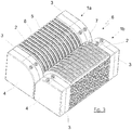
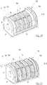
- FIG Figure 1 One possible embodiment of a first connecting link 1a is shown in FIG Figure 1 shown.
- the electrical contacts 2 are surrounded by two magnetic elements 3.
- the magnetic elements 3 are located at the two front ends of the connecting link 1a.
- the connecting member 1a has a cross-sectional area 4 in the form of a square with a rounded corner.
- the cross-sectional area 4 resembles a segment of a circle, more precisely a quarter circle segment.
- the magnetic elements 3 are designed as permanent magnets 3 and can be made from a cylinder magnet, for example.
- the magnetic elements 3 can thus have poles N, S separated in the axial direction.
- the number of contacts 2 that a connecting member 1a has can be arbitrary, preferably greater than two and less than a hundred, particularly preferably between two and fifty, very particularly preferably between ten and twenty. In the embodiment of Figure 1 thirteen contacts 2 are provided. Depressions 5 are provided between the contacts 2 in order to enable a mechanical demonstration, preferably a rough guide. The contacts 2 themselves are individually set back within electrically insulated framing elements 8.
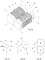
- FIG 2 a second link 1b is shown.
- This connecting member 1b is designed to be magnetically and electrically connected to the first connecting member 1a Figure 1 to be able to form a pair of connections 6.
- the thirteen contacts 2 are again surrounded by two magnetic elements 3, which are designed as permanent magnets 3.
- the two permanent magnets 3 each have a north and a south pole and are arranged at the ends of the connecting member 1b in such a way that one end of the connecting member 1b has a polarity N and the other end of the connecting member 1b has a polarity S.
- the distribution of the poles N, S is chosen to be complementary to that of the magnetic elements 3 of the first connecting member 1a.
- the arrangement of the magnetic elements 3 has the effect that the magnetic force supports the contacting of the connecting links 1a, 1b in only one orientation.
- dome-like framing elements 7 are shown for mechanical demonstration, in particular for rough guidance, in an embodiment as protruding, dome-like framing elements 7, such that the framing elements 7 of the connecting member 1b of the Figure 2 in the correspondingly formed recesses 5 of the connecting member 1 a of Figure 1 fit, it being possible to provide a certain amount of play here, so that a rough guide is preferably provided.
- the dome-like framing elements 7 each comprise an electrical contact 2 of the second connecting member 1b of the Figure 2 .
- the electrical contacts 2 are set back slightly and are preferably supported by spring elements.
- the dome-like framing elements 7 are designed in such a way that they penetrate into the recesses 5 of the connecting member 1a and thereby encompass the framing elements 8 of the contacts 2 of the connecting member 1a.
- a possible assembly of the magnetic elements 3 on the connecting links 1a, 1b or the contact part of the connecting links 1a, 1b is shown in the form of a dovetail connection 9. Another connection or fastening can also be provided here.
- the connecting links 1a, 1b of Figures 1 and 2 can be found in the dimensions AE as an example. Although the proportions of the components to one another are not to be understood as being restricted as a result and all dimensions can be scaled as required, some particularly advantageous dimensions are mentioned below.
- the height or width A of the cross-sectional area 4 or the end face of the connecting link 1a can be approximately 8 mm.
- the height or width of the cross-sectional area 4 or the end face of the connecting member 1b including the dome-like framing elements 7 protruding in height and in width is likewise approximately 8 mm. That is to say, the magnetic elements 3 of the second connecting member 1b have a height or width that is less than the height or width of the protrusion of the dome-like framing elements 7 than the magnetic elements 3 of the first connecting member 1a.
- the length B of the connecting links 1a, 1b can be approximately 20 mm.
- the distance C between the center lines of two contacts 2 can be approximately 1.05 mm.
- the width D of a contact 2, which can be arranged slightly set back in the electrically insulating frame element 8, is preferably approximately 0.3 mm.
- the width E of the electrical contact 2 of the second link 1b, the is preferably mounted radially spring-loaded and surrounded by the dome-like framing element 7, can for example be approximately 0.2 mm.
- FIG 3 is shown how the connecting links 1a, 1b of the Figures 1 and 2 form a pair of connections 6.
- the dovetail connection 9 for attaching the magnetic elements 3 to the connecting links 1a, 1b is not shown; this can be any.
- One possible implementation can also be done by gluing, for example.
- the connecting members 1a, 1b are magnetically and electrically connected to one another.
- a mechanical demonstration, in the exemplary embodiment a rough guide is provided which, however, does not hold the connecting links 1a, 1b together, but only takes on a guiding function and prevents axial movement.
- the connecting links 1a, 1b can initially be roughly approximated, whereby the magnetic elements 3, given the correct orientation, which are shown in FIG Figure 3 is shown, make the final contact exactly.
- the coding of the connecting links 1a, 1b with the aid of the magnetic poles N, S of the magnetic elements 3 ensures that the connecting links 1a, 1b only make contact in a predetermined orientation and can then be rotated with respect to one another or can roll over one another.
- the magnetic and electrical connection between the connecting members 1a, 1b of a pair of connections takes place via their jacket surface or a partial surface of the jacket surface. This is shown accordingly in all the exemplary embodiments. While the connecting links 1a, 1b roll over one another, the axes of the connecting links 1a, 1b preferably continue to run parallel to one another.
- FIG. 13 is a simplified view of the interconnection of the links of FIG Figures 1a and 2a shown, whereby the fastening of the magnetic elements 3 by means of a dovetail connection 9 - shown there - can take place.
- the connecting member 1a according to FIGS Figures 1 and 1a preferably has a housing 50, preferably made of plastic, which forms the framing elements 8.
- the housing 50 is in Figure 1a designated.
- the connecting member 1b according to FIGS Figures 2 and 2a preferably has a housing 70, preferably made of plastic, which is shown in Figure 2a is designated.
- the housing 70 preferably forms the dome-like framing elements 7.
- the Figure 4a shows the side view of a pair of connections 6. Due to the illustrated cross-sectional areas 4 of the connecting links 1a, 1b, it is possible to roll them off one another in the form of a circular movement. The course of such a movement is in the following Figures 4b and 4c indicated.
- the Figure 4a shows an orientation of zero angular degrees of the connecting links 1a, 1b relative to one another, the Figure 4b an orientation greater than ninety degrees and the Figure 4c an alignment of one hundred and eighty degrees after the full rolling motion is complete.
- the movement is of course reversible and can be repeated as often as required.
- the rotation can also be stopped permanently at any angular position. According to the invention, the magnetic or electrical contact is not lost.
- the axes of the connecting links 1a, 1b remain aligned parallel to one another while the connecting links 1a, 1b roll over one another.
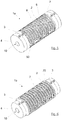
- a second embodiment show Figures 5, 6 and 7th .
- the contacts 2 are surrounded by the magnetic elements 3.
- the magnetic elements 3 are arranged at the front ends of the connecting links 1a, 1b.
- the connecting links 1a, 1b now have a cross-sectional area 4 in the form of a complete circle.
- the attachment of the magnetic elements 3 to the contact parts of the connecting links 1 a, 1 b is implemented by a connection or fastening 10, which can be designed as a round plug connection 10.
- a connection or fastening 10 which can be designed as a round plug connection 10.
- the second connecting member 1b shown has dome-like framing elements 7 in the form of circular areas with larger radii than the cross-sectional area 4.
- magnetic elements 3 are according to the Figures 1 and 2 arranged. Exactly to the contacts 2 of the connecting member 1a of the Figure 5 are in the Figure 6 corresponding contacts 2 distributed and preferably sprung.
- a resulting pair of connections 6 is spatially in the Figure 7 shown; the Figure 8 shows a side view.
- the connection pair As an extension of the exemplary embodiments according to Figures 1 to 4 it is with the connection pair after Figure 7 Due to the complete circular cross-section, it is possible to roll the connecting links 1a, 1b completely, that is to say by up to three hundred and sixty degrees and beyond, on one another.
- the connecting links 1a and 1b only roll or roll over one another over 180 degrees, this simplifies the connection of the contacts 2 of the connecting links 1a, 1b to further units.
- the contacts 2 of the connecting member 1 a are at least partially surrounded by framing elements 8.
- the framing elements 8 are encompassed by the dome-like framing elements 7 of the connecting member 1b when the dome-like framing elements 7 penetrate into the depressions 5.
- At least one contact 2 of each contact pair is preferably spring-loaded; in principle, both contacts of a contact pair 2 can also be spring-loaded.
- the connecting member 1 a preferably has a housing 50, preferably made of plastic, which forms the framing elements 8.
- the connecting member 1b preferably has a housing 70, preferably made of plastic, which forms the dome-like framing elements 7.
- FIG. 5 to 7 an arrangement of the two magnet elements 3 is shown in such a way that the first connecting member 1a has a north pole at one end and a south pole at the other end.
- the second connecting member 1b has a correspondingly complementary south pole at one end and a north pole at the other end.
- the connecting links 1a, 1b can only be closed in one orientation with magnetic support.
- the magnetic elements 3 are arranged in such a way that the first connecting member 1a has a south pole or a north pole at both end faces and the second connecting member 1b is designed in a correspondingly complementary manner, in this case a connection of the connecting members 1a, 1b is in two orientations, which around 180 degrees are rotated to each other, possible. This may be suitable for certain embodiments.
- the connecting members 1a, 1b are preferably connected to an electronic unit 11a, 11b or arranged on this or connectable to it.
- a mobile phone, a tablet or an electronic unit can preferably also be connected to a shell, a docking station, a housing, a cover, a base or a receiving part.
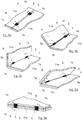
- FIGS. 9a to 9e show an exemplary application of the invention.
- Two units 11a, 11b are shown, each of which preferably has two connecting members 1a, 1b.
- the connecting links 1a, 1b preferably have two magnetic elements 3, which are preferably arranged on the front side of the connecting links 1a, 1b.
- the first unit 11a has a first connecting member 1a and a second connecting member 1b; the second unit 11b has a complementary structure.
- connection pairs 6 A total of two connection pairs 6 are formed.
- the connecting links 1a, 1b shown are preferably those of the first exemplary embodiment, ie there is a cross-section 4 in the form of a square rounded at one end. However, it can also be the connecting links 1a, 1b of the second or third exemplary embodiment.
- the units 11a, 11b shown can be identical units or else different units.
- a connection can be established between two identical or different mobile telephones, a mobile computer and a keyboard or docking station or the like.
- the Figure 13 shows a connection between two identical cell phones 12 or tablets.
- connection device makes the connection of the two units 11a, 11b flexible in an advantageous manner.
- the units 11a, 11b can be rotated relative to one another or pivoted to one another in the manner of a hinge or joint.
- One possible turning movement is beginning in its sequence in Figure 9a and ending at Figure 9e shown.
- a rotation of up to one hundred and eighty degrees of the elements 11a, 11b relative to one another is possible.
- the number of connecting links 1a, 1b in the units 11a, 11b can be arbitrary. It is also possible to use only one connecting link 1a or 1b per unit or even more than two connecting links 1a, 1b.
- By appropriately arranging the connecting links 1a, 1b, preferably symmetrically or optionally asymmetrically, and a corresponding arrangement of the magnetic elements 3 on the connecting links 1a, 1b it can be achieved that the magnetic connecting device only supports the connection of the units 11a, 11b in one orientation or a connection is also possible in two orientations (rotated by 180 angular degrees to one another) so that the alignment of the units 11a, 11b can be varied, whereby in both cases a rotation of the units 11a, 11b to one another (as in Figures 9a to 9e shown) is possible.
- the unit 11a can have connecting members 1a or connecting members 1b or a mixture, as already described above, of the connecting members 1a, 1b.
- the unit 11b can be equipped in a correspondingly complementary manner.
- each unit has a connecting member 1a and a connecting member 1b so that the units can be connected together.
- the Figure 10 shows a third embodiment for a first connecting member 1a.
- a cross-sectional area 4 in the form of a square with a rounded corner is used again.
- the contacts 2 are magnetic elements 3.
- the contact or magnetic elements 2, 3 are surrounded by a mechanical demonstration, preferably a rough guide 13, which can also serve as a frame for the simultaneous protection of all contacts 2 from short circuits.
- An embodiment with four contacts 2 is shown. This embodiment is particularly suitable for forming a USB plug connection.
- the counterpart to the in Figure 10 The first link 1a shown, the second link 1b, is shown in FIG Figure 11 shown.
- the second connecting member 1b is designed in such a way that its mechanical and magnetic guidance is complementary to that of the first connecting member 1a.
- the contacts 2 or magnetic elements 3 on the respective connecting links 1a, 1b are each equally oriented such that the north and south poles of all magnetic elements 3 of a connecting link 1a and 1b are on the same side.
- Other configurations are also possible here in order to achieve a different coding.
- not all contacts 2 are made magnetic. It can be particularly advantageous if only the power or ground contacts are made magnetic in order to avoid interference.
- other data or signal contacts in particular if slow data transmission is provided and interference is less likely, can also be designed to be magnetic.
- further magnet elements 3, which are not provided for electrical contacting can also be used in the embodiment according to FIGS Figures 10 to 12 can be added.
- the mechanical coarse guide 13 for prepositioning or for coarse positioning is provided in order to avoid an axial movement of the connecting members 1a, 1b with respect to one another.
- the axial positioning can thus be taken over in a simple manner by the mechanical rough guide, while the holding force between the connecting members 1a, 1b, in particular in the radial direction, is taken over by the magnetic force.
- the elements of the connecting links 1 a, 1 b, which form the mechanical coarse guide 13, are designed as partially annular elevations 14.
- the partially annular elevations 14 essentially follow the curved course of the jacket or surface of the connecting links 1a, 1b, ie they have an arcuate course (partially annular) which ends in a straight line at the ends.
- the two partially annular elevations 14 of the first connecting member 1a are formed on the front ends of the connecting member.
- the two partially annular elevations 14 of the second connecting member 1b are moved inwards from the end faces approximately by the thickness of the partially annular elevations 14 of the first connecting member 1a, so that the partially annular elevations 14 of the two connecting members 1a, 1b are side by side when the connecting members 1a , 1b are electrically and magnetically connected to one another.
- the formation of two such mechanical connection pairs prevents a displacement of the connecting links 1a, 1b in both axial directions of movement.
- the height and width F of the cross-sectional area 4 of the first connecting member 1a can be approximately 7.5 mm, for example.
- the height and width F of the cross-sectional area 4 of the second connecting member 1b is also approximately 7.5 mm.
- the length G of a link 1a, 1b can be approximately 15 mm.
- the distance H between the center line of two contacts 2 or magnetic elements 3 can be approximately 2.5 mm.
- the width I of a contact 2 or magnetic element 3 can be approximately 1.5 mm.
- the protrusion J by which the partially annular elevation 14 protrudes over the jacket surface can preferably be approximately 1 mm.
- the distance is selected such that when the two connecting links 1a, 1b are plugged together, the contacts 2 of the connecting links 1a, 1b make contact with one another. This is supported by a magnetic configuration of the contacts 2. Furthermore, it can be provided that one or both contacts 2 of a contact pair 2 are mounted radially spring-loaded.
- the dimensions are particularly advantageous, but the explanations are not limited to them.
- the dimensions can differ in particular +/- 80%, preferably +/- 50% and very particularly preferably +/- 20%.
- Figure 12 is the formation of a connecting pair 6 of the connecting links 1a, 1b of the third embodiment of FIG Figures 10 and 11 shown as an example.
- the illustrated units 11a, 11b can also be equipped with the connecting members 1a, 1b of the third embodiment, in particular also with the number of contacts 2 selected there.
- FIG 13 it is shown how a connection between two cell phones 12 or two tablets by two connection pairs 6 can look like.
- An embodiment is shown in which the connecting links 1a, 1b have a cross-section 4 according to the first or third embodiment of the connecting links 1a, 1b, and four contacts 2 are surrounded by magnet elements 3 arranged at the end.
- it is possible to move the cell phones 12 towards one another in the direction of the arrow.
Landscapes
- Engineering & Computer Science (AREA)
- Theoretical Computer Science (AREA)
- Computer Hardware Design (AREA)
- Human Computer Interaction (AREA)
- Physics & Mathematics (AREA)
- General Engineering & Computer Science (AREA)
- General Physics & Mathematics (AREA)
- Signal Processing (AREA)
- Computer Networks & Wireless Communication (AREA)
- Details Of Connecting Devices For Male And Female Coupling (AREA)
- Telephone Set Structure (AREA)
Claims (14)
- Dispositif de liaison magnétique pour relier deux unités, dans lequel au moins un premier élément de liaison (1a) est affecté à une première unité (11a) et au moins un second élément de liaison (1b) est affecté à une seconde unité (11b), dans lequel un premier élément de liaison (1a) et un second élément de liaison (1b) forment une paire d'éléments de liaison (6), dans lequel les éléments de liaison (1a, 1b) d'une paire d'éléments de liaison (6) présentent chacun une pluralité de contacts (2), dans lequel les éléments de liaison (1a, 1b) d'une paire d'éléments de liaison (6) sont disposés avec leurs axes parallèles et en contact magnétique l'un avec l'autre et dans lequel les éléments de liaison (1a, 1b) d'une paire d'éléments de liaison (6) peuvent pivoter l'un par rapport à l'autre lorsqu'ils sont en contact, caractérisé en ce que,
les éléments de liaison (1a, 1b) d'une paire d'éléments de liaison (6) présentent un guidage mécanique (5, 7 ou 13) agencé pour limiter un déplacement axial des éléments de liaison (1a, 1b) lorsqu'ils sont en contact, et dans lequel le guidage mécanique (5, 7 ou 13) est réalisé sous la forme d'un guidage mécanique approximatif, de sorte que le guidage mécanique approximatif permette une mise en place aisée des éléments de liaison l'un sur l'autre, et l'alignement exact et précis s'effectue alors magnétiquement. - Dispositif de liaison magnétique selon la revendication 1,
caractérisé en ce que,
les éléments de liaison (1a, 1b) d'une paire d'éléments de liaison (6) comportent chacun au moins un élément magnétique (3) pour la mise en contact magnétique et au moins un élément magnétique (3) d'une paire d'éléments de liaison (6) est réalisé sous la forme d'un aimant permanent. - Dispositif de liaison magnétique selon la revendication 2,
caractérisé en ce que,
les éléments de liaison (1a, 1b), les éléments magnétiques (3) et les contacts (2) d'une paire d'éléments de liaison (6) sont agencés de sorte que, dans le cas d'une mise en contact magnétique, les contacts (2) des éléments de liaison (1a, 1b) respectifs entrent en contact électrique les uns avec les autres. - Dispositif de liaison magnétique selon la revendication 2, ou 3,
caractérisé en ce que,
les éléments magnétiques (3) sont agencés de sorte que les éléments de liaison (1a, 1b) d'une paire d'éléments de liaison (6) peuvent entrer en contact électrique et magnétique dans au moins une orientation prédéfinie et qu'ils s'attirent magnétiquement dans cette orientation, dans lequel les éléments de liaison (1a, 1b) d'une paire d'éléments de liaison (6) sont agencés de sorte que, lorsqu'ils sont en contact, les éléments de liaison (1a, 1b) d'une paire d'éléments de liaison (6) peuvent, lors d'une rotation relative de l'un par rapport à l'autre, rouler l'un sur l'autre sur au moins une surface partielle de la surface externe des éléments de liaison (1a, 1b), le contact électrique et magnétique restant établi. - Dispositif de liaison magnétique selon l'une des revendications 2 à 4,
caractérisé en ce que,
les éléments magnétiques (3) des éléments de liaison (1a, 1b) d'une paire d'éléments de liaison (6) sont alignés en ce qui concerne leur polarité de telle sorte que les éléments de liaison (1a, 1b) d'une paire d'éléments de liaison (6) ne s'attirent magnétiquement que dans une orientation de la première unité (11a) vers la seconde unité (11b). - Dispositif de liaison magnétique selon l'une des revendications 2 à 5,
caractérisé en ce que,
chaque élément de liaison (1a, 1b) d'une paire d'éléments de liaison (6) est pourvu d'au moins deux éléments magnétiques (3). - Dispositif de liaison magnétique selon l'une des revendications 4 à 6,
caractérisé en ce que,
au moins une surface partielle des surfaces externes des éléments de liaison (1a, 1b), sur lesquelles les éléments de liaison (1a, 1b) d'une paire d'éléments de liaison (6) peuvent rouler l'un sur l'autre, est courbe et/ou arquée et/ou présente un rayon. - Dispositif de liaison magnétique selon la revendication 7,
caractérisé en ce que,
les éléments de liaison (1a, 1b) d'une paire d'éléments de liaison (6) sont en forme de tige. - Dispositif de liaison magnétique selon la revendication 8,
caractérisé en ce que,
les éléments de liaison (1a, 1b) en forme de tige sont pourvus à chacune de leurs extrémités frontales d'un élément magnétique (3) et en ce qu'une pluralité de contacts (2) est disposée entre les éléments magnétiques (3). - Dispositif de liaison magnétique selon l'une des revendications 4 à 9,
caractérisé en ce que,
les contacts (2) et/ou les éléments magnétiques (3) sont courbes et/ou arqués et/ou présentent un rayon au moins sur la longueur de la surface partielle dans la direction du pivotement des éléments de liaison (1a, 1b). - Dispositif de liaison magnétique selon l'une des revendications 2 à 10,
caractérisé en ce que,
les éléments magnétiques (3) sont réalisés en forme de cylindre et/ou de disque et/ou d'anneau et/ou d'une partie d'anneau. - Dispositif de liaison magnétique selon l'une des revendications 1 à 11,
caractérisé en ce que,
au moins une partie des contacts électriques (2) des éléments de liaison (1a, 1b) d'une paire d'éléments de liaison (6), alignés et en contact électrique, établissent un contact magnétique les uns avec les autres. - Dispositif de liaison magnétique selon la revendication 12,
caractérisé en ce que,
au moins une partie des contacts (2) est réalisée sous la forme d'éléments magnétiques (3). - Système électronique avec au moins une première unité (11a), une seconde unité (11b) et un dispositif de liaison magnétique selon l'une des revendications 1 à 13,
caractérisé en ce que,
les unités (11a, 11b) sont reliées par l'intermédiaire du dispositif de liaison magnétique.
Applications Claiming Priority (3)
| Application Number | Priority Date | Filing Date | Title |
|---|---|---|---|
| DE102014116948 | 2014-11-19 | ||
| DE102015116490.6A DE102015116490A1 (de) | 2014-11-19 | 2015-09-29 | Magnetische Verbindungsvorrichtung |
| PCT/EP2015/076145 WO2016078962A1 (fr) | 2014-11-19 | 2015-11-10 | Dispositif de liaison magnétique |
Publications (2)
| Publication Number | Publication Date |
|---|---|
| EP3221929A1 EP3221929A1 (fr) | 2017-09-27 |
| EP3221929B1 true EP3221929B1 (fr) | 2022-01-05 |
Family
ID=55855489
Family Applications (1)
| Application Number | Title | Priority Date | Filing Date |
|---|---|---|---|
| EP15791307.0A Active EP3221929B1 (fr) | 2014-11-19 | 2015-11-10 | Dispositif de liaison magnétique |
Country Status (9)
| Country | Link |
|---|---|
| US (1) | US10177490B2 (fr) |
| EP (1) | EP3221929B1 (fr) |
| JP (1) | JP2017536671A (fr) |
| KR (1) | KR20170083034A (fr) |
| CN (1) | CN107112686B (fr) |
| CA (1) | CA2965419A1 (fr) |
| DE (3) | DE102015116490A1 (fr) |
| TW (1) | TWI691125B (fr) |
| WO (1) | WO2016078962A1 (fr) |
Families Citing this family (11)
| Publication number | Priority date | Publication date | Assignee | Title |
|---|---|---|---|---|
| WO2015070321A1 (fr) * | 2013-11-13 | 2015-05-21 | Szeto Timothy Jing Yin | Connecteurs magnétiques |
| DE102015116490A1 (de) * | 2014-11-19 | 2016-05-19 | Rosenberger Hochfrequenztechnik Gmbh & Co. Kg | Magnetische Verbindungsvorrichtung |
| KR20170058081A (ko) * | 2015-11-18 | 2017-05-26 | 삼성전자주식회사 | 자석으로 연결되는 장치 |
| KR102435011B1 (ko) * | 2017-05-22 | 2022-08-23 | 삼성전자주식회사 | 액세사리를 포함하는 전자 장치 |
| TWI675282B (zh) * | 2018-05-14 | 2019-10-21 | 緯創資通股份有限公司 | 具有樞軸結構之電子裝置及其訊號連接單元的製造方法 |
| JP7413998B2 (ja) * | 2018-05-31 | 2024-01-16 | 日本ゼオン株式会社 | 連結ユニット |
| US10931058B2 (en) * | 2018-09-24 | 2021-02-23 | Apple Inc. | Gaskets for sealing spring-loaded contacts |
| US20200150728A1 (en) * | 2018-11-13 | 2020-05-14 | Microsoft Technology Licensing, Llc | Hinged device |
| CN110043555A (zh) * | 2019-03-29 | 2019-07-23 | 努比亚技术有限公司 | 一种转轴 |
| DE102019113924B4 (de) * | 2019-05-24 | 2026-01-22 | BohnenIT GmbH | Ausrichthilfe für Bildschirme |
| CN111594514A (zh) * | 2020-06-24 | 2020-08-28 | 京东方科技集团股份有限公司 | 电子显示牌系统、电子显示牌及支撑台 |
Family Cites Families (35)
| Publication number | Priority date | Publication date | Assignee | Title |
|---|---|---|---|---|
| US531515A (en) * | 1894-12-25 | Hinge for electric apparatus | ||
| JPS6079681A (ja) * | 1983-09-28 | 1985-05-07 | モレツクス・インコ−ポレ−テツド | ヒンジ付電気コネクタ− |
| JPS60166985U (ja) * | 1984-04-12 | 1985-11-06 | 星電器製造株式会社 | プリント基板接続用コネクタ |
| US4863387A (en) * | 1987-12-22 | 1989-09-05 | Snaper Alvin A | Printer circuit board separable connector |
| US4850882A (en) * | 1987-12-28 | 1989-07-25 | Wenli Yu | Rotatably mounted printed circuit board test support and connector |
| JPH067594Y2 (ja) * | 1988-03-31 | 1994-02-23 | アンプ インコーポレーテッド | 電気ヒンジコネクター |
| US4863388A (en) * | 1988-05-04 | 1989-09-05 | Ag Communication Systems Corporation | Rotating contact ZIF connector |
| US5941714A (en) * | 1997-09-23 | 1999-08-24 | Massachusetts Institute Of Technology | Digital communication, programmable functioning and data transfer using modular, hinged processor elements |
| US6272324B1 (en) * | 1998-09-28 | 2001-08-07 | Ericsson Inc. | Electrical connection for telephone with hinged cover |
| TW520809U (en) * | 2001-09-28 | 2003-02-11 | Molex Inc | Hand-held electronic device |
| CN100511875C (zh) * | 2002-05-24 | 2009-07-08 | 莫列斯公司 | 用于电子设备的铰链连接器 |
| JP3680171B2 (ja) * | 2002-07-15 | 2005-08-10 | 日本航空電子工業株式会社 | セルフ−アライメント磁石コネクタ |
| US6722892B1 (en) * | 2002-12-19 | 2004-04-20 | General Electric Company | Multi-plane adjustable connector |
| EP1704703B1 (fr) * | 2004-01-14 | 2013-08-28 | J.M. Stanneck, Limited Liability Company | Appareil a configuration variable |
| PL1674344T3 (pl) * | 2004-12-27 | 2009-06-30 | Nexans | Układ zasilania energią elektryczną odbiorników elektrycznych zainstalowanych w pojeździe mechanicznym |
| JP2006210269A (ja) * | 2005-01-31 | 2006-08-10 | Sanyo Electric Co Ltd | コネクタ |
| DE202008013600U1 (de) | 2008-08-12 | 2008-12-24 | Magcode Ag | Vorrichtung zur Herstellung einer Verbindung |
| US8323040B2 (en) * | 2008-09-05 | 2012-12-04 | Apple Inc. | Docking station with moveable connector for hand-held electronic device |
| US8187006B2 (en) * | 2009-02-02 | 2012-05-29 | Apex Technologies, Inc | Flexible magnetic interconnects |
| CN101995911B (zh) * | 2009-08-11 | 2012-10-10 | 鸿富锦精密工业(深圳)有限公司 | 笔记本电脑 |
| US20110070747A1 (en) * | 2009-09-22 | 2011-03-24 | Med-El Elektromedizinische Geraete Gmbh | Communications/Audio Interface with Self-Orienting Magnet Attachment System |
| CN201781112U (zh) * | 2010-07-22 | 2011-03-30 | 番禺得意精密电子工业有限公司 | 电连接器 |
| US8753128B2 (en) * | 2011-03-31 | 2014-06-17 | Motorola Mobility Llc | Method and apparatus for coupling portable communication devices |
| MX2014001670A (es) * | 2011-09-16 | 2014-05-27 | Framatome Connectors Int | Ensamble de conector giratorio. |
| CN103178387B (zh) * | 2011-12-21 | 2015-02-25 | 英业达股份有限公司 | 基座 |
| KR101850818B1 (ko) * | 2012-01-03 | 2018-04-23 | 삼성전자주식회사 | 모바일 기기 |
| US20140132550A1 (en) * | 2012-03-02 | 2014-05-15 | Microsoft Corporation | Electrical Contacts and Connectors |
| JP2016507841A (ja) * | 2013-01-30 | 2016-03-10 | マイクロソフト テクノロジー ライセンシング,エルエルシー | 電気接点及びコネクタ |
| US9559456B2 (en) * | 2013-03-15 | 2017-01-31 | Google Technology Holdings LLC | Magnetic electrical connection system for an electronic device |
| TWI487466B (zh) * | 2013-05-22 | 2015-06-01 | Wistron Corp | 樞紐機構及其相關電子裝置 |
| CN203445280U (zh) * | 2013-07-26 | 2014-02-19 | 富士康(昆山)电脑接插件有限公司 | 电连接器 |
| US9466920B2 (en) * | 2013-12-30 | 2016-10-11 | Foxconn Interconnect Technology Limited | Magnetic connector for electronic device |
| US20160022030A1 (en) * | 2014-07-28 | 2016-01-28 | Group Dekko, Inc. | Desktop receptacle with flip cover |
| EP3210262A4 (fr) * | 2014-10-20 | 2018-04-11 | Nanoport Technology Inc. | Connecteurs à composants magnétiques mobiles et procédé de connexion de dispositifs |
| DE102015116490A1 (de) * | 2014-11-19 | 2016-05-19 | Rosenberger Hochfrequenztechnik Gmbh & Co. Kg | Magnetische Verbindungsvorrichtung |
-
2015
- 2015-09-29 DE DE102015116490.6A patent/DE102015116490A1/de active Pending
- 2015-09-29 DE DE202015009066.4U patent/DE202015009066U1/de not_active Expired - Lifetime
- 2015-09-29 DE DE202015009067.2U patent/DE202015009067U1/de not_active Expired - Lifetime
- 2015-11-10 CA CA2965419A patent/CA2965419A1/fr not_active Abandoned
- 2015-11-10 CN CN201580058967.8A patent/CN107112686B/zh active Active
- 2015-11-10 EP EP15791307.0A patent/EP3221929B1/fr active Active
- 2015-11-10 WO PCT/EP2015/076145 patent/WO2016078962A1/fr not_active Ceased
- 2015-11-10 KR KR1020177011486A patent/KR20170083034A/ko not_active Withdrawn
- 2015-11-10 US US15/523,549 patent/US10177490B2/en active Active
- 2015-11-10 JP JP2017526936A patent/JP2017536671A/ja active Pending
- 2015-11-19 TW TW104138221A patent/TWI691125B/zh not_active IP Right Cessation
Also Published As
| Publication number | Publication date |
|---|---|
| DE102015116490A1 (de) | 2016-05-19 |
| DE202015009066U1 (de) | 2016-08-24 |
| JP2017536671A (ja) | 2017-12-07 |
| CA2965419A1 (fr) | 2016-05-26 |
| WO2016078962A1 (fr) | 2016-05-26 |
| CN107112686B (zh) | 2019-06-14 |
| CN107112686A (zh) | 2017-08-29 |
| US20170310042A1 (en) | 2017-10-26 |
| TW201630270A (zh) | 2016-08-16 |
| US10177490B2 (en) | 2019-01-08 |
| KR20170083034A (ko) | 2017-07-17 |
| TWI691125B (zh) | 2020-04-11 |
| DE202015009067U1 (de) | 2016-08-24 |
| EP3221929A1 (fr) | 2017-09-27 |
Similar Documents
| Publication | Publication Date | Title |
|---|---|---|
| EP3221929B1 (fr) | Dispositif de liaison magnétique | |
| EP3345258B1 (fr) | Armature de support pour connecteur modulaire | |
| DE102018127720B3 (de) | Hochstromsteckverbinder und Steckverbindersystem | |
| DE102013108383B4 (de) | Steckverbindermodul | |
| DE102008038641A1 (de) | Vorrichtung zur Herstellung einer Verbindung | |
| EP3014707B2 (fr) | Module de connecteur enfichable | |
| DE102008038649A1 (de) | Vorrichtung zur Herstellung einer Verbindung | |
| EP3863124B1 (fr) | Cadre de retenue pour un connecteur industriel | |
| EP2592634A2 (fr) | Appareil et procédé pour tenir des pièces magnétiques pendant la magnétisation et pour déposer les pièces magnétiques magnétisées dans un élément d'un système magnétique | |
| DE102017106946A1 (de) | Intercom-Steckverbinder für Audio-Verbindungen | |
| DE202008014989U1 (de) | Vorrichtung zur Herstellung einer Verbindung | |
| EP4010949B1 (fr) | Connecteur électrique mâle | |
| EP3849028A1 (fr) | Dispositif de connecteur enfichable et connecteur enfichable électrique | |
| WO2017206989A1 (fr) | Fiche | |
| WO2025223614A1 (fr) | Module adaptateur pour connecteur industriel modulaire | |
| DE112010004997T5 (de) | Verbindungsstruktur | |
| DE202015105134U1 (de) | Magnetische Verbindungsvorrichtung | |
| DE202019106239U1 (de) | Hochfrequenz-Prüfstiftvorrichtung | |
| WO2002043191A1 (fr) | Dispositif de chargement | |
| DE60310937T2 (de) | Anschlussvorrichtung zum Anschluss mindestens eines Geräts an eine Steckdose | |
| DE102009006048B4 (de) | Drehscharnier mit integriertem elektrischem Kontakt | |
| DE19618611C2 (de) | Selbstverstärkendes Steckverbindungselement | |
| EP4057450B1 (fr) | Appareil électrique avec un capuchon de protection intégrant un moyen de contact magnétique | |
| EP3336974A1 (fr) | Connecteur enfichable d'intercommunication pour connexions audio | |
| DE10231715A1 (de) | Symmetrischer Steckverbinder |
Legal Events
| Date | Code | Title | Description |
|---|---|---|---|
| STAA | Information on the status of an ep patent application or granted ep patent |
Free format text: STATUS: THE INTERNATIONAL PUBLICATION HAS BEEN MADE |
|
| PUAI | Public reference made under article 153(3) epc to a published international application that has entered the european phase |
Free format text: ORIGINAL CODE: 0009012 |
|
| STAA | Information on the status of an ep patent application or granted ep patent |
Free format text: STATUS: REQUEST FOR EXAMINATION WAS MADE |
|
| 17P | Request for examination filed |
Effective date: 20170421 |
|
| AK | Designated contracting states |
Kind code of ref document: A1 Designated state(s): AL AT BE BG CH CY CZ DE DK EE ES FI FR GB GR HR HU IE IS IT LI LT LU LV MC MK MT NL NO PL PT RO RS SE SI SK SM TR |
|
| AX | Request for extension of the european patent |
Extension state: BA ME |
|
| DAV | Request for validation of the european patent (deleted) | ||
| DAX | Request for extension of the european patent (deleted) | ||
| STAA | Information on the status of an ep patent application or granted ep patent |
Free format text: STATUS: EXAMINATION IS IN PROGRESS |
|
| 17Q | First examination report despatched |
Effective date: 20180724 |
|
| GRAP | Despatch of communication of intention to grant a patent |
Free format text: ORIGINAL CODE: EPIDOSNIGR1 |
|
| STAA | Information on the status of an ep patent application or granted ep patent |
Free format text: STATUS: GRANT OF PATENT IS INTENDED |
|
| GRAJ | Information related to disapproval of communication of intention to grant by the applicant or resumption of examination proceedings by the epo deleted |
Free format text: ORIGINAL CODE: EPIDOSDIGR1 |
|
| STAA | Information on the status of an ep patent application or granted ep patent |
Free format text: STATUS: EXAMINATION IS IN PROGRESS |
|
| INTG | Intention to grant announced |
Effective date: 20210706 |
|
| INTC | Intention to grant announced (deleted) | ||
| GRAP | Despatch of communication of intention to grant a patent |
Free format text: ORIGINAL CODE: EPIDOSNIGR1 |
|
| STAA | Information on the status of an ep patent application or granted ep patent |
Free format text: STATUS: GRANT OF PATENT IS INTENDED |
|
| GRAS | Grant fee paid |
Free format text: ORIGINAL CODE: EPIDOSNIGR3 |
|
| INTG | Intention to grant announced |
Effective date: 20211004 |
|
| GRAA | (expected) grant |
Free format text: ORIGINAL CODE: 0009210 |
|
| STAA | Information on the status of an ep patent application or granted ep patent |
Free format text: STATUS: THE PATENT HAS BEEN GRANTED |
|
| AK | Designated contracting states |
Kind code of ref document: B1 Designated state(s): AL AT BE BG CH CY CZ DE DK EE ES FI FR GB GR HR HU IE IS IT LI LT LU LV MC MK MT NL NO PL PT RO RS SE SI SK SM TR |
|
| REG | Reference to a national code |
Ref country code: GB Ref legal event code: FG4D Free format text: NOT ENGLISH |
|
| REG | Reference to a national code |
Ref country code: CH Ref legal event code: EP |
|
| REG | Reference to a national code |
Ref country code: AT Ref legal event code: REF Ref document number: 1461417 Country of ref document: AT Kind code of ref document: T Effective date: 20220115 |
|
| REG | Reference to a national code |
Ref country code: DE Ref legal event code: R096 Ref document number: 502015015558 Country of ref document: DE |
|
| REG | Reference to a national code |
Ref country code: IE Ref legal event code: FG4D Free format text: LANGUAGE OF EP DOCUMENT: GERMAN |
|
| REG | Reference to a national code |
Ref country code: FI Ref legal event code: FGE |
|
| REG | Reference to a national code |
Ref country code: SE Ref legal event code: TRGR |
|
| REG | Reference to a national code |
Ref country code: LT Ref legal event code: MG9D |
|
| REG | Reference to a national code |
Ref country code: NL Ref legal event code: MP Effective date: 20220105 |
|
| PG25 | Lapsed in a contracting state [announced via postgrant information from national office to epo] |
Ref country code: NL Free format text: LAPSE BECAUSE OF FAILURE TO SUBMIT A TRANSLATION OF THE DESCRIPTION OR TO PAY THE FEE WITHIN THE PRESCRIBED TIME-LIMIT Effective date: 20220105 |
|
| PG25 | Lapsed in a contracting state [announced via postgrant information from national office to epo] |
Ref country code: RS Free format text: LAPSE BECAUSE OF FAILURE TO SUBMIT A TRANSLATION OF THE DESCRIPTION OR TO PAY THE FEE WITHIN THE PRESCRIBED TIME-LIMIT Effective date: 20220105 Ref country code: PT Free format text: LAPSE BECAUSE OF FAILURE TO SUBMIT A TRANSLATION OF THE DESCRIPTION OR TO PAY THE FEE WITHIN THE PRESCRIBED TIME-LIMIT Effective date: 20220505 Ref country code: NO Free format text: LAPSE BECAUSE OF FAILURE TO SUBMIT A TRANSLATION OF THE DESCRIPTION OR TO PAY THE FEE WITHIN THE PRESCRIBED TIME-LIMIT Effective date: 20220405 Ref country code: LT Free format text: LAPSE BECAUSE OF FAILURE TO SUBMIT A TRANSLATION OF THE DESCRIPTION OR TO PAY THE FEE WITHIN THE PRESCRIBED TIME-LIMIT Effective date: 20220105 Ref country code: HR Free format text: LAPSE BECAUSE OF FAILURE TO SUBMIT A TRANSLATION OF THE DESCRIPTION OR TO PAY THE FEE WITHIN THE PRESCRIBED TIME-LIMIT Effective date: 20220105 Ref country code: ES Free format text: LAPSE BECAUSE OF FAILURE TO SUBMIT A TRANSLATION OF THE DESCRIPTION OR TO PAY THE FEE WITHIN THE PRESCRIBED TIME-LIMIT Effective date: 20220105 Ref country code: BG Free format text: LAPSE BECAUSE OF FAILURE TO SUBMIT A TRANSLATION OF THE DESCRIPTION OR TO PAY THE FEE WITHIN THE PRESCRIBED TIME-LIMIT Effective date: 20220405 |
|
| PG25 | Lapsed in a contracting state [announced via postgrant information from national office to epo] |
Ref country code: PL Free format text: LAPSE BECAUSE OF FAILURE TO SUBMIT A TRANSLATION OF THE DESCRIPTION OR TO PAY THE FEE WITHIN THE PRESCRIBED TIME-LIMIT Effective date: 20220105 Ref country code: LV Free format text: LAPSE BECAUSE OF FAILURE TO SUBMIT A TRANSLATION OF THE DESCRIPTION OR TO PAY THE FEE WITHIN THE PRESCRIBED TIME-LIMIT Effective date: 20220105 Ref country code: GR Free format text: LAPSE BECAUSE OF FAILURE TO SUBMIT A TRANSLATION OF THE DESCRIPTION OR TO PAY THE FEE WITHIN THE PRESCRIBED TIME-LIMIT Effective date: 20220406 |
|
| PG25 | Lapsed in a contracting state [announced via postgrant information from national office to epo] |
Ref country code: IS Free format text: LAPSE BECAUSE OF FAILURE TO SUBMIT A TRANSLATION OF THE DESCRIPTION OR TO PAY THE FEE WITHIN THE PRESCRIBED TIME-LIMIT Effective date: 20220505 |
|
| REG | Reference to a national code |
Ref country code: DE Ref legal event code: R097 Ref document number: 502015015558 Country of ref document: DE |
|
| PG25 | Lapsed in a contracting state [announced via postgrant information from national office to epo] |
Ref country code: SM Free format text: LAPSE BECAUSE OF FAILURE TO SUBMIT A TRANSLATION OF THE DESCRIPTION OR TO PAY THE FEE WITHIN THE PRESCRIBED TIME-LIMIT Effective date: 20220105 Ref country code: SK Free format text: LAPSE BECAUSE OF FAILURE TO SUBMIT A TRANSLATION OF THE DESCRIPTION OR TO PAY THE FEE WITHIN THE PRESCRIBED TIME-LIMIT Effective date: 20220105 Ref country code: RO Free format text: LAPSE BECAUSE OF FAILURE TO SUBMIT A TRANSLATION OF THE DESCRIPTION OR TO PAY THE FEE WITHIN THE PRESCRIBED TIME-LIMIT Effective date: 20220105 Ref country code: EE Free format text: LAPSE BECAUSE OF FAILURE TO SUBMIT A TRANSLATION OF THE DESCRIPTION OR TO PAY THE FEE WITHIN THE PRESCRIBED TIME-LIMIT Effective date: 20220105 Ref country code: DK Free format text: LAPSE BECAUSE OF FAILURE TO SUBMIT A TRANSLATION OF THE DESCRIPTION OR TO PAY THE FEE WITHIN THE PRESCRIBED TIME-LIMIT Effective date: 20220105 Ref country code: CZ Free format text: LAPSE BECAUSE OF FAILURE TO SUBMIT A TRANSLATION OF THE DESCRIPTION OR TO PAY THE FEE WITHIN THE PRESCRIBED TIME-LIMIT Effective date: 20220105 |
|
| PLBE | No opposition filed within time limit |
Free format text: ORIGINAL CODE: 0009261 |
|
| STAA | Information on the status of an ep patent application or granted ep patent |
Free format text: STATUS: NO OPPOSITION FILED WITHIN TIME LIMIT |
|
| PG25 | Lapsed in a contracting state [announced via postgrant information from national office to epo] |
Ref country code: AL Free format text: LAPSE BECAUSE OF FAILURE TO SUBMIT A TRANSLATION OF THE DESCRIPTION OR TO PAY THE FEE WITHIN THE PRESCRIBED TIME-LIMIT Effective date: 20220105 |
|
| 26N | No opposition filed |
Effective date: 20221006 |
|
| PG25 | Lapsed in a contracting state [announced via postgrant information from national office to epo] |
Ref country code: SI Free format text: LAPSE BECAUSE OF FAILURE TO SUBMIT A TRANSLATION OF THE DESCRIPTION OR TO PAY THE FEE WITHIN THE PRESCRIBED TIME-LIMIT Effective date: 20220105 |
|
| P01 | Opt-out of the competence of the unified patent court (upc) registered |
Effective date: 20230515 |
|
| PG25 | Lapsed in a contracting state [announced via postgrant information from national office to epo] |
Ref country code: MC Free format text: LAPSE BECAUSE OF FAILURE TO SUBMIT A TRANSLATION OF THE DESCRIPTION OR TO PAY THE FEE WITHIN THE PRESCRIBED TIME-LIMIT Effective date: 20220105 |
|
| REG | Reference to a national code |
Ref country code: BE Ref legal event code: MM Effective date: 20221130 |
|
| PG25 | Lapsed in a contracting state [announced via postgrant information from national office to epo] |
Ref country code: LU Free format text: LAPSE BECAUSE OF NON-PAYMENT OF DUE FEES Effective date: 20221110 |
|
| PG25 | Lapsed in a contracting state [announced via postgrant information from national office to epo] |
Ref country code: IE Free format text: LAPSE BECAUSE OF NON-PAYMENT OF DUE FEES Effective date: 20221110 |
|
| PG25 | Lapsed in a contracting state [announced via postgrant information from national office to epo] |
Ref country code: BE Free format text: LAPSE BECAUSE OF NON-PAYMENT OF DUE FEES Effective date: 20221130 |
|
| REG | Reference to a national code |
Ref country code: AT Ref legal event code: MM01 Ref document number: 1461417 Country of ref document: AT Kind code of ref document: T Effective date: 20221110 |
|
| PG25 | Lapsed in a contracting state [announced via postgrant information from national office to epo] |
Ref country code: AT Free format text: LAPSE BECAUSE OF NON-PAYMENT OF DUE FEES Effective date: 20221110 |
|
| PG25 | Lapsed in a contracting state [announced via postgrant information from national office to epo] |
Ref country code: HU Free format text: LAPSE BECAUSE OF FAILURE TO SUBMIT A TRANSLATION OF THE DESCRIPTION OR TO PAY THE FEE WITHIN THE PRESCRIBED TIME-LIMIT; INVALID AB INITIO Effective date: 20151110 |
|
| PG25 | Lapsed in a contracting state [announced via postgrant information from national office to epo] |
Ref country code: CY Free format text: LAPSE BECAUSE OF FAILURE TO SUBMIT A TRANSLATION OF THE DESCRIPTION OR TO PAY THE FEE WITHIN THE PRESCRIBED TIME-LIMIT Effective date: 20220105 |
|
| PG25 | Lapsed in a contracting state [announced via postgrant information from national office to epo] |
Ref country code: MK Free format text: LAPSE BECAUSE OF FAILURE TO SUBMIT A TRANSLATION OF THE DESCRIPTION OR TO PAY THE FEE WITHIN THE PRESCRIBED TIME-LIMIT Effective date: 20220105 |
|
| PG25 | Lapsed in a contracting state [announced via postgrant information from national office to epo] |
Ref country code: MT Free format text: LAPSE BECAUSE OF FAILURE TO SUBMIT A TRANSLATION OF THE DESCRIPTION OR TO PAY THE FEE WITHIN THE PRESCRIBED TIME-LIMIT Effective date: 20220105 |
|
| PGFP | Annual fee paid to national office [announced via postgrant information from national office to epo] |
Ref country code: DE Payment date: 20241128 Year of fee payment: 10 |
|
| PGFP | Annual fee paid to national office [announced via postgrant information from national office to epo] |
Ref country code: FI Payment date: 20241126 Year of fee payment: 10 |
|
| PGFP | Annual fee paid to national office [announced via postgrant information from national office to epo] |
Ref country code: GB Payment date: 20241126 Year of fee payment: 10 |
|
| PGFP | Annual fee paid to national office [announced via postgrant information from national office to epo] |
Ref country code: FR Payment date: 20241126 Year of fee payment: 10 |
|
| PGFP | Annual fee paid to national office [announced via postgrant information from national office to epo] |
Ref country code: IT Payment date: 20241125 Year of fee payment: 10 |
|
| PGFP | Annual fee paid to national office [announced via postgrant information from national office to epo] |
Ref country code: SE Payment date: 20241126 Year of fee payment: 10 |
|
| PGFP | Annual fee paid to national office [announced via postgrant information from national office to epo] |
Ref country code: CH Payment date: 20241201 Year of fee payment: 10 |
|
| PG25 | Lapsed in a contracting state [announced via postgrant information from national office to epo] |
Ref country code: TR Free format text: LAPSE BECAUSE OF FAILURE TO SUBMIT A TRANSLATION OF THE DESCRIPTION OR TO PAY THE FEE WITHIN THE PRESCRIBED TIME-LIMIT Effective date: 20220105 |