EP2592634A2 - Appareil et procédé pour tenir des pièces magnétiques pendant la magnétisation et pour déposer les pièces magnétiques magnétisées dans un élément d'un système magnétique - Google Patents
Appareil et procédé pour tenir des pièces magnétiques pendant la magnétisation et pour déposer les pièces magnétiques magnétisées dans un élément d'un système magnétique Download PDFInfo
- Publication number
- EP2592634A2 EP2592634A2 EP12191828.8A EP12191828A EP2592634A2 EP 2592634 A2 EP2592634 A2 EP 2592634A2 EP 12191828 A EP12191828 A EP 12191828A EP 2592634 A2 EP2592634 A2 EP 2592634A2
- Authority
- EP
- European Patent Office
- Prior art keywords
- magazine
- magnetic
- elements
- cavity
- component
- Prior art date
- Legal status (The legal status is an assumption and is not a legal conclusion. Google has not performed a legal analysis and makes no representation as to the accuracy of the status listed.)
- Granted
Links
Images







Classifications
-
- H—ELECTRICITY
- H01—ELECTRIC ELEMENTS
- H01F—MAGNETS; INDUCTANCES; TRANSFORMERS; SELECTION OF MATERIALS FOR THEIR MAGNETIC PROPERTIES
- H01F13/00—Apparatus or processes for magnetising or demagnetising
- H01F13/003—Methods and devices for magnetising permanent magnets
Definitions
- the invention relates to a device and a method for holding magnetic bodies during their magnetization and for introducing the magnetized magnetic body into a component of a magnetic system such as an electromagnetic drive, a magnetic path or angle system or the like.
- the invention further relates to a handling system for magnetic body having such a device and an associated magnetization arrangement such as a coil arrangement for magnetizing the magnet body accommodated in the magazine.
- the invention has for its object to reduce the time and cost in the production of a magnetic system such as an electromagnetic drive, a magnetic path or angle system or the like, which include permanent magnets.
- the device according to the invention is characterized in that it is designed as a magazine with a plurality of cavities each for receiving at least one magnetic body, wherein the magazine has a plurality of interconnected and mutually movable magazine elements. In this case, a single magazine element has at least one cavity for receiving a magnetic body.
- the handling of the magnetic bodies to be magnetized and to be introduced into a component of a magnetic system is substantially simplified. Due to the design of the magazine with a plurality of mutually movable magazine elements with a plurality of magnetic bodies received in the cavities, the device or its magazine elements can be optimally aligned both for magnetization, as well as for the subsequent introduction of the magnetized magnetic body in the component of the magnetic system , For example, a rotor or rotor of a permanent magnet generator. In this way, in particular, an automation of the necessary work steps can be provided, which represents a considerable production time and cost savings.
- a respective cavity in the magazine does not have to represent a closed cavity, but can also have or as a rule have at least one opening, in particular for the introduction and removal of the magnetic body associated with this cavity.
- a cavity can also be formed by a slot or groove in the magazine or a magazine element, this groove or slot providing a cavity for receiving at least one magnet body.
- a said cavity in a magazine or a magazine element can be designed to receive a magnet body shaped in a certain way, for example for receiving cuboid or cylindrical magnet bodies, wherein the cavity can be adapted to the shape of the magnetic body to be accommodated.
- Such an adaptation can in particular consist in that a received magnetic body rests at least in sections on the inner wall of the cavity.
- a magazine element can also have a plurality of, for example, two or three cavities, wherein each cavity in turn can accommodate a single magnetic body or even a plurality of magnetic bodies depending on the particular special application.
- the magazine may be formed of a non-magnetic material such as an austenitic steel, whereby the mobility of the magnetic body within the cavities of the magazine, for example, when inserting and / or deploying the magnetic body simplified because the magnetized magnetic body is not magnetically connected to the material of Magazine can interact.
- a non-magnetic material such as an austenitic steel
- the magazine may expediently be formed straight from magnetizable material or comprise such, for example in order to optimize the magnetizing field during magnetization of the magnet body accommodated in the cavities of the magazine.
- magazine elements of the device are connected to each other like a chain or limb, such that at least one magazine element is in each case movably connected to two adjacent magazine elements.
- each magazine element is a single link of this chain.
- exactly one individual degree of freedom of movement is provided between two directly adjacent magazine elements, which facilitates the handling of the magazine.
- This degree of freedom is provided in the simplest case by an axis of rotation about which adjacent magazine elements are arranged rotatably relative to each other.
- the former may be particularly advantageous in the magnetization of the magnetic body held in the magazine, in particular by a linear coil for the magnetization can be used.
- a formability of the magazine such that a circular or circular segment shape is adjustable may be particularly useful if after magnetization, the magnetic body in a generally circular rotor or rotor must be introduced, which can be simulated due to the mobility of the individual magazine elements to each other ,
- This "replica" of the rotor has the consequence that a plurality of cavities of the magazine with cavities of the rotor can be aligned with each other, so that the transfer of stored in the cavities of the magazine magnetic body in associated cavities of the rotor greatly simplified.
- the magazine according to the invention further facilitates the handling of the magazine, in particular in order to carry out the transfer of the magazine from a first shape to a second shape.
- a magazine according to the invention Due to the two degrees of freedom between adjacent magazine elements relative movability of the two adjacent magazine elements is increased to each other, so that such a magazine according to the invention is particularly easy to bring in the form of a straight chain or in a circular or circular segment shape to magnetize, for example held in the magazine magnets when the magazine has the shape of a linear chain and the magnet body after magnetization in a magnet system when the magazine is converted into a circular segment shape, as has been explained above with reference to a magazine according to the invention, in which a single Degree of freedom between two adjacent magazine elements is provided.
- the provision of two degrees of freedom between two adjacent magazine elements can be realized in that between adjacent magazine elements an elongate connecting element is arranged, which is hinged to both adjacent magazine elements rotatably, where appropriate, both associated axes of rotation can be oriented parallel to each other.
- the elongated connecting element is rigidly designed to limit the movement between two adjacent magazine elements exactly to the two said degrees of freedom.
- the arrangement of the elongated connecting element between adjacent magazine elements can be designed such that after adjusting the circular or circular segment shape of the magazine axes of rotation, in particular all axes of rotation for coupling the respective connecting elements to the magazine elements on a Circle or circular section lie, wherein the circumferential spacing of the two axes of rotation of a magazine element is smaller than half of the entire circumferential extent of a magazine element.
- the two axes of rotation of a magazine element extend through it, wherein the circumferential distance between these axes of rotation is limited as indicated.
- a cavity of a magazine element for receiving a magnetic body on an extension edge which is oriented approximately parallel to the axis of rotation of the interconnected and adjacent magazine elements.
- other orientations of the cavity relative to the axis of rotation of the connected and adjacent magazine elements may be expedient, for example, in those cases in which the magnetic body must be transferred from the magazine into a rotor, in which the cavities do not run parallel to the axis of the rotor, but tilts to this.
- adjacent magazine elements have cooperating stop surfaces for defining mutual orientation layers, in particular for fixing two end positions in the mutual movement of two adjacent and connected magazine elements.
- a multiplicity of connecting devices can be used to connect two adjacent magazine elements. The only condition is that this connection means allows relative movement of the interconnected magazine elements.
- a particularly simple design of such a connecting device provides a Hinge connection.
- a cavity of a magazine element expediently has an opening which in most applications does not have to be designed to be closable.
- the latter expediently has a support, in particular opposite to the opening.
- such a cavity in a magazine element can also be open on two sides, in particular on opposite sides, for example in those cases in which the material arranged to the surrounding cavity can be magnetized so that the magnetic body is magnetically held in the cavity.
- two adjacent and interconnected magazine elements each have complementary locking devices for locking at least one mutual Location of the two magazine elements.
- a lock can be realized, for example, by means of a resilient latching element which is attached to one of the magazine elements, which snaps into each other in an assigned orientation of the adjacent magazine elements in an associated latching recess on the adjacent magazine element.
- the latching can be suitably designed so that it can be repealed with an increased effort and the two adjacent and latched magazine elements are again freely movable to each other.
- the main body of the magazine elements may be connected in a chain-like manner, such that at least one main body of a magazine element is movably connected to the two basic bodies of the adjacent magazine elements.
- two degrees of freedom of movement are provided between the basic bodies of adjacent magazine elements, wherein the two degrees of freedom of movement are rotary degrees of freedom.
- an elongated connecting element can be arranged between the basic bodies of two adjacent magazine elements, which is pivotably articulated on both adjacent basic bodies, wherein both associated axes of rotation are oriented parallel to one another.
- the magazine is expediently brought into the form of a substantially rectilinear chain by aligning the base body of the magazine elements which is movable relative to one another and / or into a circular or circular segment shape, so that the device according to the invention for the magnetization and / or the introduction of the magnetic body into the magnetic system Optimized is customizable.
- the movement of the magnetic body sensor arranged rotatably relative to the main body can be realized in different ways according to the invention.
- the Magnetoresierillon to the main body can be arranged manually rotatable to the main body.
- the provision of a respective controllable electrical or mechanical drive is possible.
- Particularly useful is a design in which a Magnet Economicsaufêt is motion-coupled to the main body of an adjacent magazine element, said motion coupling can be designed such that with the orientation of the mutually movable base body adjacent magazine elements automatically the Magnet Economicsaufstream is rotated to its main body.
- this movement coupling can be designed such that when setting a linear chain of the magazine, the held magnetic bodies are aligned in a predetermined manner to the magnetizing field and / or when setting a second shape of the magazine such as a circular segment shape, the held magnetic body with respect to their magnetization optimized for insertion into the component of the magnetic system are oriented.
- the magazine recorded magnetic body need not be magnetized in all embodiments simultaneously. It is also possible, for example, to introduce the magazine in sections and in a clocked manner into a magnetization device, so that in a plurality of steps the magnetic bodies held in the magazine are magnetized. In this case, a shape of the magazine assigned to the magazine section located in the magnetization device can also be set at each cycle.
- the loading of the magazine with a plurality of magnetic bodies on the one hand comprise the introduction of the respective magnetic body in the respectively associated cavity in the magazine.
- this step may include the introduction and solidification of magnetic particles in the cavities of the magazine, so that in this embodiment of the method according to the invention also the production of the magnetic body takes place in the magazine.
- metal powders and plastic binders can be introduced in this embodiment, the magnetic bodies then solidify in the cavity and can subsequently be subjected to the magnetization step and ultimately converted into a component of a magnetic system.
- the step of magnetizing the magnetic bodies held in the magazine comprises at least inserting the loaded magazine into a magnetizing coil, energizing the magnetizing coil to generate the magnetizing field, and removing the magazine from the magnetizing coil.
- the step of transferring the magnetized magnetic bodies into a component may be suitably performed of a magnetic system, at least aligning the populated magazine in its second shape with the component of the magnetic system, and deploying the magnetic bodies from the respective cavities in the magazine and inserting the magnetic bodies into associated cavities in the component of the magnetic system.
- alignment may be provided, for example, by aligning the openings of the cavities of the magazine with openings of associated cavities in said component of the magnetic system by orienting the magazine in its second shape to the component.
- each magnet body can be transferred individually from a cavity in the magazine into the associated cavity of the component of the magnetic system, for example by means of a push finger.
- a great saving of time results when using a thrust temple with a plurality of fingers, which are aligned in each case a cavity in the magazine and on which in a single operation a plurality of magnetic bodies, particularly suitably all magnetic body simultaneously transferred to the component of the magnetic system, in particular be moved.
- the use of two or more of the magazines described above may also be provided.
- the magnetization of the magnetic body in the different magazines may be different and held in the two magazines magnetic bodies in succession be introduced into the component of a magnetic system.
- the invention further relates to a handling system for magnetic bodies comprising a magazine according to the above configurations and a magnetization arrangement such as a coil arrangement for magnetizing the magnetic body accommodated in the magazine.
- a magnetization arrangement such as a coil arrangement for magnetizing the magnetic body accommodated in the magazine.
- this magnetization arrangement is formed on the geometry of the magazine, in particular the orientation of the magnetic body accommodated in the magazine for generating a predetermined and directed magnetization.
- the handling system expediently also comprises a device for transferring the magnetized magnet body from the magazine into the component of the magnetic system, for example in the form of a thrust temple with a multiplicity of fingers, which are each associated with a cavity in order to place the magnet bodies in associated cavities in the component of the magnetic system to transfer, for example, to move.
- a device for transferring the magnetized magnet body from the magazine into the component of the magnetic system for example in the form of a thrust temple with a multiplicity of fingers, which are each associated with a cavity in order to place the magnet bodies in associated cavities in the component of the magnetic system to transfer, for example, to move.
- this has a plate-shaped guide device with a guide groove.
- This guide groove comprises at least two sections merging into one another, wherein the guide groove is circular in a first section and circular in a second section, wherein a magazine in the guide groove is forcibly guided to sequentially adjust the first and second shapes of the magazine.
- the magazine has projections which engage in the guide groove of the guide device and thus the magazine is forcibly guided.
- the positive guidance can be such that the magazine is driven, in particular by a motor, by a first shape, for example a linear chain, in which the magnetization of the magnetic body takes place, in a second shape, for example, a circular or circular segment-shaped shape can be converted, in which the magnetic body can be converted into a component of a magnetic system, such as a rotor of an electric motor.
- a first shape for example a linear chain
- a second shape for example, a circular or circular segment-shaped shape
- the magnetic body can be converted into a component of a magnetic system, such as a rotor of an electric motor.
- the projections are arranged at the location of the axes of rotation of the mutually movable magazine elements, wherein the projections may extend parallel to the axis of rotation, in particular in the form of extensions of a rotation axis as Drehachszapfen.
- a magazine element of the magazine two axes of rotation are assigned, via which the magazine element is respectively coupled to a connecting element, which may be elongated and is coupled at its other end by means of a rotation axis to an adjacent magazine element.
- a particularly expedient embodiment of a trained handling system is designed in such a plate-shaped guide means two spaced guide grooves, each comprising at least two merging sections are designed, both guide grooves in a first section straight and parallel to each other and in a second section circular can run with opposite direction of rotation to each other.
- a design for example, the simultaneous handling, in particular the introduction and magnetization of magnetic bodies in two spaced-apart magazines, which can be provided by the transfer of the magazines in the second shape due to the opposite rotational sense, magnetic body with mutually offset by 180 degrees magnetization , which successively into a component of a electrical system such as a rotor of an electric motor can be transferred. It is expedient if both forcibly guided in the guide means magazines are moved by means of a single drive device which simultaneously acts on both magazines.
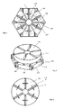
- FIG. 1 shows an inventively designed magazine 1 in a plan that is composed of a plurality of magazine elements 100 whose shape from the FIGS. 2a-c is reproduced, wherein the FIGS. 2a, b a perspective view and Figure 2 c a plan view of the front side 102 of the magazine element 100 represents.
- Each magazine element 100 is made entirely of austenitic steel, for example by means of wire eroding or milling, and has an approximately triangular base area.
- the base of a magazine element 100 in the illustrated embodiment is an approximately three-sided triangle, so that each two intersecting sides have an angle of 60 °.
- each of the magazine elements 100 Run approximately centrally and perpendicular to the base surface 108, each of the magazine elements 100 on a receptacle or cavity 101 for receiving a magnetic body 2.
- the open cavity extends over the entire thickness of the magazine element, ie between the front side 102 and the rear side 103 of the element.
- This support ring 140 is formed in the embodiment described also from a non-magnetic steel and screwed, for example via a circumferentially mounted on the support ring external thread in an associated flat thread on the back 103 of the magazine element 100.
- the support ring can also be easily glued to the back 103 of the magazine element 100, in turn such that a introduced into the cavity 101 magnetic body 2 is supported.
- each magazine element side surfaces 106, 107 and 108 shows, in the described embodiment, each magazine element side surfaces 106, 107 and 108, wherein at least the first two serve in the handling of the magazine as abutment surfaces, hereinafter, in particular, with reference to FIG. 4 , will be discussed in more detail.
- FIG. 2 has a magazine element 100 at the two corners of the side of the triangular base, to which the cavity 101 is perpendicular, complementary trained connecting elements, via which two directly adjacent magazine elements are movably connected.
- the coupling is realized via a hinge connection between the individual magazine elements 100.
- magazine elements 100 comprise at one of the two end points of said side two spaced hinge legs 110, 120, which each have mutually aligned bores 112.
- a single, also perforated hinge leg 130 is provided. This is arranged so that it can be inserted between the two legs 110, 120 of an adjacent magazine element, wherein the bore in the leg 130 then aligned with the holes in the legs 110, 120 of the adjacent magazine element, such that by means of a rivet bolt 3, please refer FIG. 1 that can complete mobile coupling of adjacent magazine elements.
- the magazine according to the invention can be constructed by the juxtaposition of a plurality of magazine elements 100, which are arranged as links of a chain.
- the magazine 6 according to the invention has six magazine elements 100 which, as described, each have a base area of an equilateral triangle, which will be discussed in greater detail below.
- the entire magazine can ultimately be converted into any desired number of design forms by the relative movement of all magazine elements to its respective neighbors.
- each magazine element in the described embodiment in addition to the already indicated abutment surfaces 106, 107 even more stop surfaces in the region of the hinge legs, which are provided with the reference numerals 115, 125 and 135.
- this relates, on the one hand, to the lateral end faces 115, 125 of the two adjacent hinge legs 110, 120 as well as those on both sides of the hinge leg 130 in the illustration according to FIG Figure 2c perpendicular to the drawing plane extending stop surfaces 135th As from the Figure 2c shows, only one of these two stop surfaces 135 is visible, the underlying in the drawing figure stop surface is covered by the leg 130.
- the magazine according to the invention can be easily in a first, predetermined and in FIG. 1 transfer shown shape, in which the magnetic body 2 are each oriented perpendicular to the longitudinal axis of the link chain.
- the magnetic bodies are produced by means of a known powder metallurgical process, which will not be discussed in more detail below.
- the shape is cuboidal in accordance with the cavity 101, wherein the dimensions are slightly smaller than that of the cavity, so that no jamming of the magnetic body can occur in the cavity.
- the magnetic bodies are completely received by the cavity 101, i. they do not protrude beyond the front side 102 of the magazine element 100. In other embodiments this is not the case, i. the magnetic body has a greater extent in the direction between the front and back of the magazine element than the magazine element is thick.
- each with an associated magnetic body 2 and the setting of in FIG. 1 illustrated shape of the magazine 1 may include in an associated coil assembly 5 six individual coils 5a - 5f are introduced.
- the spacing of these individual coils is designed such that the respective magnetic body is arranged approximately axially in the center of its associated coil and thus "sees" a homogeneous magnetic field for the predetermined alignment of the elementary magnets.
- Plotted arrows indicate the respective direction of the magnetic field H for the sub-coils 5a - 5f. Due to the different, in FIG. 3 specified current directions in the coil sections adjacent magnet body are magnetized opposite each other in the magazine. It is understood that this magnetization direction can be selected as desired depending on the application, in particular by adjusting the current direction in the coils.
- the latter can be removed from the magnet assembly 5 and transferred from the first shape to a second shape to transmit the magnetized magnetic body 2, for example in cavities of a rotor, which represents the rotor of a permanent magnet generator.
- This second configuration of the chain 1 shows FIG. 4 , As indicated, adjacent magazine elements 100 are tilted against each other such that the respective abutment surfaces 106, 107 abut against each other and thus the six members having an equilateral base occupy together a closed annular shape.
- the respective magnetization B of magnetic particles adjacent to the magazine runs in opposite directions due to the above-described current directions in adjacent coils 5a-5f.
- FIG. 5 shows that according to FIG. 4 set magazine 100 below a rotor 150 with cavities 151, in which the magazine held by the magnetized magnet body are transferred.
- the rotor 150 and the magazine 100 are aligned axially with each other.
- This situation shows FIG. 5 , Since the geometry of the magazine or the relative position of the cavities are adapted to each other in the described second shape of the magazine shape to the relative position of the cavities of the rotor, the cavities of both devices 100, 150 can bring to cover.
- the magnetized magnetic body 2 by simple, in the present case, axial displacement of the magnetic body from the cavities 101 of the magazine in the cavities 151 of the rotor can be transferred.
- the magnetized magnet bodies 2 are pressed by the rear side 103 of the magazine elements 100 in the direction of the front side 102 and ultimately pushed out of the respective cavity 101 and pushed into the associated cavity 151.
- This process can be carried out in particular by means not shown, which is designed as a punch with a plurality of fingers, which moves by moving the punch axially to the magazine 100 and the rotor 150, the magnetized magnet body in the cavities 151 of the rotor.
- the stamping device described can be designed in such a way that all magnetic bodies are simultaneously transferred from their respective cavities 101 into the associated cavities 151 in the rotor 150 in one operation.
- the assembled rotor 150 shows FIG. 6 .
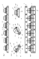
- FIGS. 7-12 show a second embodiment of the invention, which will be discussed below to avoid repetition alone on the differences. Accordingly, the same features are provided with the same reference numerals in the figures.
- the magazine 1 ' again six magazine elements 100', each magazine element 100 '
- two separate cavities 101 ', 101 " which run parallel and differently spaced to the side surface 108. Both cavities 101', 101" are in turn open to the front 102 of the magazine element 100 ', on the back is the support ring 140, which blocked back openings of the cavities 101 ', 101 "and thus the two imported magnetic body 2', 2" carries.
- the further design of the magazine 1 'or of the magazine elements 100' does not differ from that of the first embodiment.
- FIG. 9 shows that in FIG. 7
- the magnet arrangement 5 'or its coil windings are oriented in such a way that the alternating magnetic field H, indicated in the longitudinal direction of the coil arrangement, is introduced in a first embodiment. which is symbolized by the illustrated arrows, in a corresponding manner, the elementary magnets are aligned in the magnetic bodies.
- FIG. 10 shows the magazine in its second by relatively moving the magazine elements 100 'converted shape shape, which also represents a closed circular shape in this embodiment in the plan view.
- the magnetization B of the magnetic bodies 2 ', 2 "in the second shape of the shape of the magazine is in the radial direction while being tangent in the first embodiment.
- FIG. 11 again shows the orientation of the cavities 151 ', 151 "of the rotor 150' to the cavities 101 ', 101" of the magazine 100' for transmitting the magnetic magnet body accommodated in the magazine in the rotor.
- the assembled rotor 150 ' shows FIG. 12 .
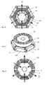
- FIGS. 13 to 18 show a third embodiment of the invention, wherein in turn below essentially addresses the differences from the above-described embodiments. Again, the same components are provided with identical reference numerals.
- the magazine 1 "exactly three magazine elements 100", each magazine element 100 "similar to the magazine 1 according to FIG. 1 a single cavity 101 ", whose longitudinal axis in turn is substantially perpendicular and central to the side surface 108, see FIG. 14 a) to c) runs.
- the two side legs 106, 107 together form in contrast to the magazine element according to FIG. 1 an angle of 120 °.
- the cavity 101 is in turn open towards the front side 102 of the magazine element 100", on the rear side 103 there is the support ring 140 which blocks the rear opening of the cavity 101 "and thus carries an inserted magnet body " of the FIG. 13 is connected to its adjacent magazine elements, which are constructed identically to the central magazine element, again by means of the hinge connection explained with reference to the above embodiments. Also in the third embodiment, associated abutment surfaces on adjacent magazine elements 100 "cooperate for easy adjustment of predetermined pivotal positions of the individual magazine elements 100".
- FIGS. 15 a), b) each show a in FIG. 13 illustrated magazine which is inserted into an associated coil assembly 5 "a and 5" b in its first shape.
- the two coils 5 "a and 5" b differ with respect to the field direction, so that the magnetization of the magnetic bodies accommodated in the cavities 101 "of the magazines (which in the interests of simplicity are incorporated into the magazines) FIGS. 13-15 not yet shown) in mutually opposite directions.
- This different orientation of the magnetization in the two in FIG. 15 illustrated, otherwise identical magazines goes out of the FIGS.
- FIGS. 17 a), b) again show the respective orientation of the cavities 151 of the rotor 150 to the cavities 101 "of the respective magazine 100" for the transmission of the magnetized magnet bodies 2 "a, 2" b accommodated in the two magazines into the rotor.
- a first transfer step the magnetic bodies 2 "a contained in the one magazine are transferred from the magazine to the rotor 150, as already described with reference to the first two embodiments, showing the result of the first transfer step FIG. 18 a) .
- the equipped with the magnetic bodies 2 "a rotor is raised to the second magazine, which carries the magnetized magnetic body 2" b, see FIGS. 16 b), 17 b).
- FIG. 18 b) shown end result ie the fully equipped with the magnetic bodies 2 "a, 2" b rotor 150th
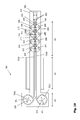
- FIGS. 19 to 24 show first a plan view of the handling system 300, which has a flat, elongated guide plate 310 in the described embodiment. Approximately symmetrical to the center, two spaced guide grooves 312a, b are arranged, which extend in the sections A1, A2 in a straight line with a constant distance parallel to each other. Within the section A3, the two guide grooves in each case in a circular shape with opposite direction of rotation over.
- the guide plate is made of a plastic, but it may for example also be made of a composite material or metal.
- Each of the two guide grooves 312a, b is associated with a magazine 199, which in the given embodiment each comprises four magazine elements 200 each having a single cavity 201 for receiving a magnetic body. Magazine elements 200 which are directly adjacent to one another are each coupled to one another by means of a connecting element designed as a pivoting arm 215. For this purpose, bores are provided in the magazine element 200 through which respective pin axes 210, 211 extends, wherein in the described embodiment, a pin axis further extends through associated bores at each end of the pivot arm 215 so that it is rotatably hinged to the magazine element 200.
- the magazine elements and the pivot arms are made of metal.
- the two magazines 199 which each comprise four magazine elements 200 in the described embodiment, are each articulated by means of a coupling arm 220 to a coupling element 230 in the form of a cuboid element, the coupling arm 220 on a magazine element 200 in the figure right in the manner already described hinged, as described for the connecting elements respectively pivoting arms 215 above.
- a pin axis 231 through an associated hole in the coupling element 230 passes, whereby the coupling arm 220 is rotatably hinged to the coupling element 230.
- the articulation of the coupling arm 220 to a magazine element and the coupling element 230 is therefore equal to the articulation of a pivot arm 215 to two adjacent magazine elements, wherein the axial length of a coupling arm 220 and a pivot arm 215 may be different.
- all pivot arms 215 have the same axial length between the magazine elements.
- all pivot arms can be identical, like all magazine elements.
- the specified pin axes 210, 211 and 231 respectively extend in the direction of the guide plate 310 into the guide grooves 212a and 212b. They protrude with axle journal in the respective guide groove, so that both magazines are positively guided in the guide grooves when moving the coupling element 230.
- move the coupling element 230 in the plane parallel to the guide grooves to the left move the two magazines with their magazine elements in the sections A1 and A2 initially in the form of a linear chain, said after entering the area A3, this linear chain due to the design the two guide grooves 312a, b is converted into a circular shape.
- the magazine elements and the coupling element can each rest with a flat end face on the flat plate and are moved slightly to move the magazines on the plate due to low adhesion and sliding friction between the guide plate 310 and the magazine elements 200.
- the materials of the magazine elements and the guide plate are selected adapted.
- the handling system according to Fig. 19 has in section A2 a linear coil assembly 250, which is shown cut in the figure. Inside by one of the two Guide grooves 312a, b formed circle in the guide plate each have a central bore 320 and 4 circumferentially equidistantly spaced holes 321 are arranged, the latter are on an imaginary circle centric to the central bore 320.
- FIG. 20 shows the design of a single magazine element 200 in a perspective view.
- all the magazine elements are identical, wherein the magazine elements 200 of the two magazines 199 merge into one another by rotation of 180 ° about an axis, wherein this axis is perpendicular to the axes 210, 211.
- the magazine elements have a crescent-shaped basic shape, wherein a cavity 201 for receiving a magnetic body extends through the volume of the magazine element 200 therethrough.
- Holes 203a, 203b and 204a, 204b are provided parallel to the longitudinal extension of the cavity 201, which correspond in each case to one another and are spaced apart from one another by a recess 202 in the body of the magazine element 200.
- this recess protrude in FIG. 19 illustrated pivot arms 215 into it or the element 220 in the magazine element 200, which is arranged directly adjacent to the coupling element 230.
- FIG. 21 A perspective view of the in FIG. 19 shown handling system is in FIG. 21 played.
- the magnetization coil assembly 250 is different from the illustration in FIG. 19 not cut, but completely stated. In the simplest embodiment, it may be formed as a linear coil.
- the drive for moving the two magazines to the coupling element 230 hinged drive, for example in the form of a linear drive, is not shown for the sake of simplicity.
- the respective cavities 201 of the eight magazine elements 200 can be occupied with magnetic bodies. This can be realized for example so that the individual cavities 201 are successively populated from above with magnetic bodies.
- a magnetic body feed arranged in the section A1 above the two magazines is again provided, from which the magnetic bodies can be introduced simultaneously into all cavities of the magazine elements, ie with a single working step. In each case, a magnetic body is placed over an associated cavity 201 and all magnetic bodies are simultaneously transferred, each with an associated facial expression, into the cavities 201 of the magazine elements. After fitting the magazine elements within the section A1, see FIG.
- Both magazines are transferred by means of the described positive guidance in the magnetization device in the form of a coil assembly 250, which is arranged in the section A2.
- the coil assembly is designed as a simple linear coil which generates an axial magnetic field, whereby the arranged in the cavities 201 of the magazine elements magnetic body of both magazines are magnetized simultaneously.
- the magnetization bodies used are exemplified in the described embodiment, such anisotropic design that they alone in the in FIG. 21 can be magnetized with the reference character U magnetization axis or - orientation.
- U magnetization axis or - orientation
- the reference character U magnetization axis or - orientation
- these directions are at an angle to the coil axis, which defines the magnetic field direction in the axial coil arrangement used.
- the component of the field generated by the coil arrangement which is parallel to the possible direction of magnetization U, acts. Since the angle between the possible directions of magnetization and the field direction is comparatively small, the magnetic field generated by the coil arrangement 250 is sufficient to magnetize the inserted magnetic bodies.
- FIG. 22 shows the situation or position of the coupled magazines, in which both magazines and the magazine elements 200 of both magazines within the coil, that is arranged in the section A2 for performing the magnetization.
- the coupling element 230 and thus both magazines in the figure is moved to the left on the drive, not shown, so that both magazines in the section A3, see FIG. 19 be transferred.
- the respective linear shape of the magazines merges into a circular, as in FIG. 23 is shown in a perspective view. Due to the transfer of the two magazines in a circular shape with different rotation, the orientation of the magnetization of the magnetic body in the described embodiment for both magazines is rotated by 180 degrees.
- Fig. 23 in each case only one of the magazine elements is equipped with a magnet body 4 or 4 'in both magazines, the opposite magnetization M1 or M2 of this magnet body being indicated.
- FIG. 24 shows this situation the Fig. 23 in a plan view, again showing the coil assembly 250 cut to simplify the illustration.
- the section A3 provides a transfer section in which the magnetized magnetic bodies held in both magazines can be converted into a component of a magnetic system such as a rotor of an electric motor.
- the magnet bodies stored and magnetized in the cavities 201 can be pushed out of the cavity and as described above for the reference to FIGS FIGS. 10 to 12 or 16 to 18 described embodiment are transferred. How out FIG.
- both magazines are transferred by the positive guide in the guide plate in a circular shape, in which abut the four magazine elements of a magazine with associated contact surfaces circumferentially, wherein the two, a magazine element associated axes of rotation defined by the arrangement of the two pin axes 230th , 231, have a circumferential distance ⁇ that is less than half the circumferential extent ⁇ of a single magazine.
- the transfer of the magnetic body is initially carried out on one of the two magazines, wherein all magnetic body of the magazine have the same direction of magnetization.
- the component is linearly guided over the second magazine and the stored there and reversed to the first magazine magnetized magnet body transferred into the component, so that the magnetization direction of the arranged in the component magnet body is realized alternately, as required for example in a rotor of an electric motor can.
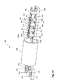
- FIGS. 25 and 26 Another embodiment of a magazine designed according to the invention will be described with reference to FIGS Figures 25 and 26 explained.
- this embodiment of a magazine is similar to that with reference to FIGS FIGS. 19-24 designed magazine designed.
- this magazine has 399 Magazine elements 400, which are composed of a base body 400a and a recorded from the main body Magnetoresier 400b, which is cylindrical in the described embodiment and rotatably arranged to this base body.
- Base body 400a adjacent magazine elements are in turn coupled to each other via pivot arms 415, which are each rotatably articulated to a base body, see FIG. 25 , which shows a magazine element designed in this way, which is transferred in the illustration shown in a first design form of a linear chain.
- the Magnetoresierillon 400b is cylindrical, with a respective cavity 401 extending parallel to the cylinder axis, see Fig. 26 ,
- FIG. 25 shown inventively designed magazine is designed so that in a transformation of the magazine of the in FIG. 25 indicated linear shape, the cavities 401 and thus the magazine body contained therein are automatically brought into a predetermined orientation.
- a rigid rotary arm 417 is pivotably connected via a pin axis 418 to the Magnet Economicsaufillon 400b, said rotary arm on the adjacent magazine element 400 and its base 400a is articulated, see Fig. 25 ,
- the articulation of the rotary arm 417 on the adjacent magazine element 400 on the same pin axis 410, at which the pivot arm 415 for connecting to the adjacent Body is hinged.
- FIG. 25 specified magazine 399 similar as in the FIGS. 21-24 shown for the magazine described therein, forcibly guided by means of a guide plate that pins of the pin axes engage in the guide plate, arises when setting a particular shape of the magazine by the coupling of a Magnet Economicsaufillons 400b with the base 400a of the adjacent magazine element 400 a predetermined orientation of the cavity 401 and thus a recorded there magnetic body.
- the respective desired orientation can be adjusted by a corresponding geometric arrangement and articulation of the rotary arm 417 to the Magnet Economicsaufillon or the main body. This in FIG.
- 25 illustrated magazine 399 has the advantage that automatically adjust the respective orientations of the magnetic body without a manual rotation of the Magnet Economicsetzêt within the respective magazine element, in particular for the magnetization of the magnetic body and / or for the introduction of the magnetic body in a component of a magnetic Systems such as a rotor must be performed.
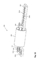
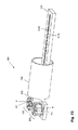
- FIG. 26 For clarity of illustration shows FIG. 26 a single magazine element 400 of the magazine according to FIG. 25 , This in FIG. 26 illustrated magazine element is different from that in FIG. 20
- the base body 400a has a cylindrical recess in which the magnet body receiver 400b rotatably extends.
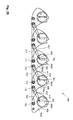
- FIGS. 27a, b, c show in schematic representations exemplary embodiments of magazines according to the invention, all have been converted into a circular shape and which differ by the respective orientation of the cavities or the magnetization of the magnetic body contained therein.
- Such magnet body arrangements are easily realizable, which can then be transferred as described, for example, in a rotor of an electromagnetic drive.
Landscapes
- Engineering & Computer Science (AREA)
- Power Engineering (AREA)
- Permanent Field Magnets Of Synchronous Machinery (AREA)
- Feeding Of Articles To Conveyors (AREA)
Applications Claiming Priority (1)
| Application Number | Priority Date | Filing Date | Title |
|---|---|---|---|
| DE201110086214 DE102011086214A1 (de) | 2011-11-11 | 2011-11-11 | Verfahren und Vorrichtung zum Halten von Magnetkörpern während ihrer Magnetisierung und zum Einbringen der magnetisierten Magnetkörpern in ein Bauteil eines magnetischen Systems |
Publications (3)
| Publication Number | Publication Date |
|---|---|
| EP2592634A2 true EP2592634A2 (fr) | 2013-05-15 |
| EP2592634A3 EP2592634A3 (fr) | 2014-01-08 |
| EP2592634B1 EP2592634B1 (fr) | 2016-06-08 |
Family
ID=47294668
Family Applications (1)
| Application Number | Title | Priority Date | Filing Date |
|---|---|---|---|
| EP12191828.8A Active EP2592634B1 (fr) | 2011-11-11 | 2012-11-08 | Appareil et procede pour tenir des pieces magnetiques pendant la magnetisation et pour deposer les pieces magnetiques magnetisees dans un element d'un systeme magnetique |
Country Status (3)
| Country | Link |
|---|---|
| US (1) | US9013257B2 (fr) |
| EP (1) | EP2592634B1 (fr) |
| DE (1) | DE102011086214A1 (fr) |
Families Citing this family (13)
| Publication number | Priority date | Publication date | Assignee | Title |
|---|---|---|---|---|
| US9673684B2 (en) | 2015-10-02 | 2017-06-06 | E-Circuit Motors, Inc. | Structures and methods for thermal management in printed circuit board stators |
| US11527933B2 (en) | 2015-10-02 | 2022-12-13 | E-Circuit Motors, Inc. | Stator and rotor design for periodic torque requirements |
| US9859763B2 (en) | 2015-10-02 | 2018-01-02 | E-Circuit Motors, Inc. | Structures and methods for controlling losses in printed circuit boards |
| US11121614B2 (en) | 2017-06-05 | 2021-09-14 | E-Circuit Motors, Inc. | Pre-warped rotors for control of magnet-stator gap in axial flux machines |
| US10170953B2 (en) | 2015-10-02 | 2019-01-01 | E-Circuit Motors, Inc. | Planar composite structures and assemblies for axial flux motors and generators |
| US9673688B2 (en) | 2015-10-02 | 2017-06-06 | E-Circuit Motors, Inc. | Apparatus and method for forming a magnet assembly |
| US9800109B2 (en) | 2015-10-02 | 2017-10-24 | E-Circuit Motors, Inc. | Structures and methods for controlling losses in printed circuit boards |
| US11005322B2 (en) | 2017-06-05 | 2021-05-11 | E-Circuit Motors, Inc. | Rotor assemblies for axial flux machines |
| US11831211B2 (en) | 2017-06-05 | 2023-11-28 | E-Circuit Motors, Inc. | Stator and rotor design for periodic torque requirements |
| JP7784674B2 (ja) | 2021-02-17 | 2025-12-12 | イー-サーキット モーターズ, インコーポレイテッド | 軸方向磁束機械のための平面固定子構成 |
| MX2024001426A (es) | 2021-07-30 | 2024-05-14 | E Circuit Motors Inc | Placas de circuito impreso rellenas de material magnetico y estatores de placas de circuito impreso. |
| US11336130B1 (en) | 2021-08-17 | 2022-05-17 | E-Circuit Motors, Inc. | Low-loss planar winding configurations for an axial flux machine |
| JP7567851B2 (ja) * | 2022-04-04 | 2024-10-16 | 横河電機株式会社 | 磁石保持装置、磁化装置および着磁方法 |
Citations (1)
| Publication number | Priority date | Publication date | Assignee | Title |
|---|---|---|---|---|
| DE102009028881A1 (de) | 2009-08-26 | 2011-03-03 | Robert Bosch Gmbh | Verfahren und Vorrichtung zur Herstellung eines Magneten |
Family Cites Families (6)
| Publication number | Priority date | Publication date | Assignee | Title |
|---|---|---|---|---|
| JPS6037698B2 (ja) * | 1979-02-19 | 1985-08-28 | ソニー株式会社 | マグネツト自動插入装置 |
| US4444550A (en) * | 1982-10-20 | 1984-04-24 | Loubier Robert J | Permanent magnet mold apparatus for injection molding plastic bonded magnets |
| DE3807368A1 (de) * | 1988-03-07 | 1989-09-21 | Fischer Artur Werke Gmbh | Magazin mit mehreren spreizduebeln |
| JP2004270544A (ja) * | 2003-03-07 | 2004-09-30 | Matsushita Electric Ind Co Ltd | 着磁治具および電動圧縮機ならびに回転子の組み立て方法および電動圧縮機の組み立て方法 |
| JP2010147214A (ja) * | 2008-12-18 | 2010-07-01 | Alps Electric Co Ltd | 永久磁石の着磁方法 |
| DE102009048343B4 (de) * | 2009-10-07 | 2014-02-20 | Deckel Maho Seebach Gmbh | Werkzeug-Kettenmagazin |
-
2011
- 2011-11-11 DE DE201110086214 patent/DE102011086214A1/de not_active Ceased
-
2012
- 2012-11-08 EP EP12191828.8A patent/EP2592634B1/fr active Active
- 2012-11-09 US US13/673,388 patent/US9013257B2/en active Active
Patent Citations (1)
| Publication number | Priority date | Publication date | Assignee | Title |
|---|---|---|---|---|
| DE102009028881A1 (de) | 2009-08-26 | 2011-03-03 | Robert Bosch Gmbh | Verfahren und Vorrichtung zur Herstellung eines Magneten |
Also Published As
| Publication number | Publication date |
|---|---|
| US9013257B2 (en) | 2015-04-21 |
| US20130141193A1 (en) | 2013-06-06 |
| EP2592634A3 (fr) | 2014-01-08 |
| DE102011086214A1 (de) | 2013-05-16 |
| EP2592634B1 (fr) | 2016-06-08 |
Similar Documents
| Publication | Publication Date | Title |
|---|---|---|
| EP2592634B1 (fr) | Appareil et procede pour tenir des pieces magnetiques pendant la magnetisation et pour deposer les pieces magnetiques magnetisees dans un element d'un systeme magnetique | |
| EP3221929B1 (fr) | Dispositif de liaison magnétique | |
| EP1843454B1 (fr) | Unité d'engrenage et support d'outil doté d'une telle unité d'engrenage | |
| DE202008016179U1 (de) | Verbindungsmittel zum Herstellen einer Verbindung eines ersten Bauteils und eines zweiten Bauteils | |
| DE202008016178U1 (de) | Verbindungsmittel zum Herstellen einer Verbindung eines ersten Bauteils und eines zweiten Bauteils | |
| EP1816727A2 (fr) | Moteur électrique | |
| EP3646438B1 (fr) | Moteur à excitation par aimants permanents, doté de tiges magnétiques rotatives | |
| EP3234967B1 (fr) | Dispositif et procédé de magnétisation d'aimants permanents | |
| DE102015014628A1 (de) | Rotorbauelement, Drehachse, Rotor, Motor und Werkzeugmaschine | |
| EP2829860B1 (fr) | Dispositif de fixation de contrepoids pour l'équilibrage de balourd | |
| DE2208034A1 (de) | Selbsteinmittende Lagerung unter Verwendung von Permanentmagneten | |
| DE102009053727A1 (de) | Zykloidgetriebe | |
| DE102012108031A1 (de) | Halter für eine Fügevorrichtung | |
| DE2931093C2 (fr) | ||
| DE102016219480A1 (de) | Montagevorrichtung zum gleichzeitigen Einführen von Kupferstäben | |
| DE102011089985A1 (de) | Verfahren zur Herstellung eines Rotors einer Transversalflussmaschine | |
| EP2084805A2 (fr) | Stator de moteur électrique | |
| EP2172121B1 (fr) | Clip | |
| EP3841659B1 (fr) | Station de fabrication compacte pour assembler un stator pour moteur électrique à partir de segments de stator | |
| DE102012101824A1 (de) | Kleinmotor und Lageranordnung | |
| DE102017207546A1 (de) | Gekrümmter magnet und herstellungsverfahren | |
| DE102010029681B4 (de) | Magnetische Haltevorrichtung | |
| DE102021131130A1 (de) | Klemmvorrichtung und -verfahren | |
| DE202021101548U1 (de) | Drehmomentscharnier und Vorrichtung mit Drehmomentscharnier | |
| DE3005921A1 (de) | Monostabiles drehankersystem |
Legal Events
| Date | Code | Title | Description |
|---|---|---|---|
| PUAI | Public reference made under article 153(3) epc to a published international application that has entered the european phase |
Free format text: ORIGINAL CODE: 0009012 |
|
| AK | Designated contracting states |
Kind code of ref document: A2 Designated state(s): AL AT BE BG CH CY CZ DE DK EE ES FI FR GB GR HR HU IE IS IT LI LT LU LV MC MK MT NL NO PL PT RO RS SE SI SK SM TR |
|
| AX | Request for extension of the european patent |
Extension state: BA ME |
|
| PUAL | Search report despatched |
Free format text: ORIGINAL CODE: 0009013 |
|
| AK | Designated contracting states |
Kind code of ref document: A3 Designated state(s): AL AT BE BG CH CY CZ DE DK EE ES FI FR GB GR HR HU IE IS IT LI LT LU LV MC MK MT NL NO PL PT RO RS SE SI SK SM TR |
|
| AX | Request for extension of the european patent |
Extension state: BA ME |
|
| RIC1 | Information provided on ipc code assigned before grant |
Ipc: H01F 13/00 20060101AFI20131202BHEP |
|
| 17P | Request for examination filed |
Effective date: 20140708 |
|
| RBV | Designated contracting states (corrected) |
Designated state(s): AL AT BE BG CH CY CZ DE DK EE ES FI FR GB GR HR HU IE IS IT LI LT LU LV MC MK MT NL NO PL PT RO RS SE SI SK SM TR |
|
| GRAP | Despatch of communication of intention to grant a patent |
Free format text: ORIGINAL CODE: EPIDOSNIGR1 |
|
| INTG | Intention to grant announced |
Effective date: 20160308 |
|
| GRAS | Grant fee paid |
Free format text: ORIGINAL CODE: EPIDOSNIGR3 |
|
| GRAA | (expected) grant |
Free format text: ORIGINAL CODE: 0009210 |
|
| AK | Designated contracting states |
Kind code of ref document: B1 Designated state(s): AL AT BE BG CH CY CZ DE DK EE ES FI FR GB GR HR HU IE IS IT LI LT LU LV MC MK MT NL NO PL PT RO RS SE SI SK SM TR |
|
| REG | Reference to a national code |
Ref country code: GB Ref legal event code: FG4D Free format text: NOT ENGLISH |
|
| REG | Reference to a national code |
Ref country code: CH Ref legal event code: EP |
|
| REG | Reference to a national code |
Ref country code: IE Ref legal event code: FG4D Free format text: LANGUAGE OF EP DOCUMENT: GERMAN |
|
| REG | Reference to a national code |
Ref country code: AT Ref legal event code: REF Ref document number: 805747 Country of ref document: AT Kind code of ref document: T Effective date: 20160715 |
|
| REG | Reference to a national code |
Ref country code: DE Ref legal event code: R096 Ref document number: 502012007347 Country of ref document: DE |
|
| REG | Reference to a national code |
Ref country code: NL Ref legal event code: MP Effective date: 20160608 |
|
| REG | Reference to a national code |
Ref country code: LT Ref legal event code: MG4D |
|
| PG25 | Lapsed in a contracting state [announced via postgrant information from national office to epo] |
Ref country code: LT Free format text: LAPSE BECAUSE OF FAILURE TO SUBMIT A TRANSLATION OF THE DESCRIPTION OR TO PAY THE FEE WITHIN THE PRESCRIBED TIME-LIMIT Effective date: 20160608 Ref country code: FI Free format text: LAPSE BECAUSE OF FAILURE TO SUBMIT A TRANSLATION OF THE DESCRIPTION OR TO PAY THE FEE WITHIN THE PRESCRIBED TIME-LIMIT Effective date: 20160608 Ref country code: NL Free format text: LAPSE BECAUSE OF FAILURE TO SUBMIT A TRANSLATION OF THE DESCRIPTION OR TO PAY THE FEE WITHIN THE PRESCRIBED TIME-LIMIT Effective date: 20160608 Ref country code: NO Free format text: LAPSE BECAUSE OF FAILURE TO SUBMIT A TRANSLATION OF THE DESCRIPTION OR TO PAY THE FEE WITHIN THE PRESCRIBED TIME-LIMIT Effective date: 20160908 |
|
| REG | Reference to a national code |
Ref country code: FR Ref legal event code: PLFP Year of fee payment: 5 |
|
| PG25 | Lapsed in a contracting state [announced via postgrant information from national office to epo] |
Ref country code: RS Free format text: LAPSE BECAUSE OF FAILURE TO SUBMIT A TRANSLATION OF THE DESCRIPTION OR TO PAY THE FEE WITHIN THE PRESCRIBED TIME-LIMIT Effective date: 20160608 Ref country code: ES Free format text: LAPSE BECAUSE OF FAILURE TO SUBMIT A TRANSLATION OF THE DESCRIPTION OR TO PAY THE FEE WITHIN THE PRESCRIBED TIME-LIMIT Effective date: 20160608 Ref country code: SE Free format text: LAPSE BECAUSE OF FAILURE TO SUBMIT A TRANSLATION OF THE DESCRIPTION OR TO PAY THE FEE WITHIN THE PRESCRIBED TIME-LIMIT Effective date: 20160608 Ref country code: LV Free format text: LAPSE BECAUSE OF FAILURE TO SUBMIT A TRANSLATION OF THE DESCRIPTION OR TO PAY THE FEE WITHIN THE PRESCRIBED TIME-LIMIT Effective date: 20160608 Ref country code: HR Free format text: LAPSE BECAUSE OF FAILURE TO SUBMIT A TRANSLATION OF THE DESCRIPTION OR TO PAY THE FEE WITHIN THE PRESCRIBED TIME-LIMIT Effective date: 20160608 Ref country code: GR Free format text: LAPSE BECAUSE OF FAILURE TO SUBMIT A TRANSLATION OF THE DESCRIPTION OR TO PAY THE FEE WITHIN THE PRESCRIBED TIME-LIMIT Effective date: 20160909 |
|
| PG25 | Lapsed in a contracting state [announced via postgrant information from national office to epo] |
Ref country code: CZ Free format text: LAPSE BECAUSE OF FAILURE TO SUBMIT A TRANSLATION OF THE DESCRIPTION OR TO PAY THE FEE WITHIN THE PRESCRIBED TIME-LIMIT Effective date: 20160608 Ref country code: IT Free format text: LAPSE BECAUSE OF FAILURE TO SUBMIT A TRANSLATION OF THE DESCRIPTION OR TO PAY THE FEE WITHIN THE PRESCRIBED TIME-LIMIT Effective date: 20160608 Ref country code: RO Free format text: LAPSE BECAUSE OF FAILURE TO SUBMIT A TRANSLATION OF THE DESCRIPTION OR TO PAY THE FEE WITHIN THE PRESCRIBED TIME-LIMIT Effective date: 20160608 Ref country code: EE Free format text: LAPSE BECAUSE OF FAILURE TO SUBMIT A TRANSLATION OF THE DESCRIPTION OR TO PAY THE FEE WITHIN THE PRESCRIBED TIME-LIMIT Effective date: 20160608 Ref country code: SK Free format text: LAPSE BECAUSE OF FAILURE TO SUBMIT A TRANSLATION OF THE DESCRIPTION OR TO PAY THE FEE WITHIN THE PRESCRIBED TIME-LIMIT Effective date: 20160608 Ref country code: IS Free format text: LAPSE BECAUSE OF FAILURE TO SUBMIT A TRANSLATION OF THE DESCRIPTION OR TO PAY THE FEE WITHIN THE PRESCRIBED TIME-LIMIT Effective date: 20161008 |
|
| PGFP | Annual fee paid to national office [announced via postgrant information from national office to epo] |
Ref country code: FR Payment date: 20161124 Year of fee payment: 5 Ref country code: GB Payment date: 20161124 Year of fee payment: 5 |
|
| PG25 | Lapsed in a contracting state [announced via postgrant information from national office to epo] |
Ref country code: BE Free format text: LAPSE BECAUSE OF NON-PAYMENT OF DUE FEES Effective date: 20161130 Ref country code: PL Free format text: LAPSE BECAUSE OF FAILURE TO SUBMIT A TRANSLATION OF THE DESCRIPTION OR TO PAY THE FEE WITHIN THE PRESCRIBED TIME-LIMIT Effective date: 20160608 Ref country code: SM Free format text: LAPSE BECAUSE OF FAILURE TO SUBMIT A TRANSLATION OF THE DESCRIPTION OR TO PAY THE FEE WITHIN THE PRESCRIBED TIME-LIMIT Effective date: 20160608 Ref country code: PT Free format text: LAPSE BECAUSE OF FAILURE TO SUBMIT A TRANSLATION OF THE DESCRIPTION OR TO PAY THE FEE WITHIN THE PRESCRIBED TIME-LIMIT Effective date: 20161010 |
|
| REG | Reference to a national code |
Ref country code: DE Ref legal event code: R097 Ref document number: 502012007347 Country of ref document: DE |
|
| PLBE | No opposition filed within time limit |
Free format text: ORIGINAL CODE: 0009261 |
|
| STAA | Information on the status of an ep patent application or granted ep patent |
Free format text: STATUS: NO OPPOSITION FILED WITHIN TIME LIMIT |
|
| 26N | No opposition filed |
Effective date: 20170309 |
|
| PG25 | Lapsed in a contracting state [announced via postgrant information from national office to epo] |
Ref country code: SI Free format text: LAPSE BECAUSE OF FAILURE TO SUBMIT A TRANSLATION OF THE DESCRIPTION OR TO PAY THE FEE WITHIN THE PRESCRIBED TIME-LIMIT Effective date: 20160608 Ref country code: DK Free format text: LAPSE BECAUSE OF FAILURE TO SUBMIT A TRANSLATION OF THE DESCRIPTION OR TO PAY THE FEE WITHIN THE PRESCRIBED TIME-LIMIT Effective date: 20160608 |
|
| REG | Reference to a national code |
Ref country code: CH Ref legal event code: PL |
|
| PG25 | Lapsed in a contracting state [announced via postgrant information from national office to epo] |
Ref country code: LI Free format text: LAPSE BECAUSE OF NON-PAYMENT OF DUE FEES Effective date: 20161130 Ref country code: CH Free format text: LAPSE BECAUSE OF NON-PAYMENT OF DUE FEES Effective date: 20161130 |
|
| REG | Reference to a national code |
Ref country code: IE Ref legal event code: MM4A |
|
| PG25 | Lapsed in a contracting state [announced via postgrant information from national office to epo] |
Ref country code: LU Free format text: LAPSE BECAUSE OF NON-PAYMENT OF DUE FEES Effective date: 20161130 |
|
| PG25 | Lapsed in a contracting state [announced via postgrant information from national office to epo] |
Ref country code: IE Free format text: LAPSE BECAUSE OF NON-PAYMENT OF DUE FEES Effective date: 20161108 |
|
| REG | Reference to a national code |
Ref country code: BE Ref legal event code: MM Effective date: 20161130 |
|
| PG25 | Lapsed in a contracting state [announced via postgrant information from national office to epo] |
Ref country code: HU Free format text: LAPSE BECAUSE OF FAILURE TO SUBMIT A TRANSLATION OF THE DESCRIPTION OR TO PAY THE FEE WITHIN THE PRESCRIBED TIME-LIMIT; INVALID AB INITIO Effective date: 20121108 Ref country code: CY Free format text: LAPSE BECAUSE OF FAILURE TO SUBMIT A TRANSLATION OF THE DESCRIPTION OR TO PAY THE FEE WITHIN THE PRESCRIBED TIME-LIMIT Effective date: 20160608 |
|
| PG25 | Lapsed in a contracting state [announced via postgrant information from national office to epo] |
Ref country code: MK Free format text: LAPSE BECAUSE OF FAILURE TO SUBMIT A TRANSLATION OF THE DESCRIPTION OR TO PAY THE FEE WITHIN THE PRESCRIBED TIME-LIMIT Effective date: 20160608 Ref country code: MC Free format text: LAPSE BECAUSE OF FAILURE TO SUBMIT A TRANSLATION OF THE DESCRIPTION OR TO PAY THE FEE WITHIN THE PRESCRIBED TIME-LIMIT Effective date: 20160608 Ref country code: TR Free format text: LAPSE BECAUSE OF FAILURE TO SUBMIT A TRANSLATION OF THE DESCRIPTION OR TO PAY THE FEE WITHIN THE PRESCRIBED TIME-LIMIT Effective date: 20160608 |
|
| GBPC | Gb: european patent ceased through non-payment of renewal fee |
Effective date: 20171108 |
|
| PG25 | Lapsed in a contracting state [announced via postgrant information from national office to epo] |
Ref country code: BG Free format text: LAPSE BECAUSE OF FAILURE TO SUBMIT A TRANSLATION OF THE DESCRIPTION OR TO PAY THE FEE WITHIN THE PRESCRIBED TIME-LIMIT Effective date: 20160608 |
|
| REG | Reference to a national code |
Ref country code: FR Ref legal event code: ST Effective date: 20180731 |
|
| PG25 | Lapsed in a contracting state [announced via postgrant information from national office to epo] |
Ref country code: MT Free format text: LAPSE BECAUSE OF FAILURE TO SUBMIT A TRANSLATION OF THE DESCRIPTION OR TO PAY THE FEE WITHIN THE PRESCRIBED TIME-LIMIT Effective date: 20160608 |
|
| PG25 | Lapsed in a contracting state [announced via postgrant information from national office to epo] |
Ref country code: FR Free format text: LAPSE BECAUSE OF NON-PAYMENT OF DUE FEES Effective date: 20171130 Ref country code: AL Free format text: LAPSE BECAUSE OF FAILURE TO SUBMIT A TRANSLATION OF THE DESCRIPTION OR TO PAY THE FEE WITHIN THE PRESCRIBED TIME-LIMIT Effective date: 20160608 |
|
| PG25 | Lapsed in a contracting state [announced via postgrant information from national office to epo] |
Ref country code: GB Free format text: LAPSE BECAUSE OF NON-PAYMENT OF DUE FEES Effective date: 20171108 |
|
| REG | Reference to a national code |
Ref country code: AT Ref legal event code: MM01 Ref document number: 805747 Country of ref document: AT Kind code of ref document: T Effective date: 20171108 |
|
| PG25 | Lapsed in a contracting state [announced via postgrant information from national office to epo] |
Ref country code: AT Free format text: LAPSE BECAUSE OF NON-PAYMENT OF DUE FEES Effective date: 20171108 |
|
| PGFP | Annual fee paid to national office [announced via postgrant information from national office to epo] |
Ref country code: DE Payment date: 20260128 Year of fee payment: 14 |