EP3222373A1 - Verfahren und anlage zur additiven fertigung metallischer formkörper - Google Patents
Verfahren und anlage zur additiven fertigung metallischer formkörper Download PDFInfo
- Publication number
- EP3222373A1 EP3222373A1 EP17160904.3A EP17160904A EP3222373A1 EP 3222373 A1 EP3222373 A1 EP 3222373A1 EP 17160904 A EP17160904 A EP 17160904A EP 3222373 A1 EP3222373 A1 EP 3222373A1
- Authority
- EP
- European Patent Office
- Prior art keywords
- granules
- cooling
- heat transfer
- transfer fluid
- space
- Prior art date
- Legal status (The legal status is an assumption and is not a legal conclusion. Google has not performed a legal analysis and makes no representation as to the accuracy of the status listed.)
- Granted
Links
Images

Classifications
-
- B—PERFORMING OPERATIONS; TRANSPORTING
- B23—MACHINE TOOLS; METAL-WORKING NOT OTHERWISE PROVIDED FOR
- B23K—SOLDERING OR UNSOLDERING; WELDING; CLADDING OR PLATING BY SOLDERING OR WELDING; CUTTING BY APPLYING HEAT LOCALLY, e.g. FLAME CUTTING; WORKING BY LASER BEAM
- B23K9/00—Arc welding or cutting
- B23K9/04—Welding for other purposes than joining, e.g. built-up welding
- B23K9/042—Built-up welding on planar surfaces
-
- B—PERFORMING OPERATIONS; TRANSPORTING
- B22—CASTING; POWDER METALLURGY
- B22F—WORKING METALLIC POWDER; MANUFACTURE OF ARTICLES FROM METALLIC POWDER; MAKING METALLIC POWDER; APPARATUS OR DEVICES SPECIALLY ADAPTED FOR METALLIC POWDER
- B22F10/00—Additive manufacturing of workpieces or articles from metallic powder
- B22F10/20—Direct sintering or melting
- B22F10/22—Direct deposition of molten metal
-
- B—PERFORMING OPERATIONS; TRANSPORTING
- B22—CASTING; POWDER METALLURGY
- B22F—WORKING METALLIC POWDER; MANUFACTURE OF ARTICLES FROM METALLIC POWDER; MAKING METALLIC POWDER; APPARATUS OR DEVICES SPECIALLY ADAPTED FOR METALLIC POWDER
- B22F12/00—Apparatus or devices specially adapted for additive manufacturing; Auxiliary means for additive manufacturing; Combinations of additive manufacturing apparatus or devices with other processing apparatus or devices
- B22F12/20—Cooling means
-
- B—PERFORMING OPERATIONS; TRANSPORTING
- B22—CASTING; POWDER METALLURGY
- B22F—WORKING METALLIC POWDER; MANUFACTURE OF ARTICLES FROM METALLIC POWDER; MAKING METALLIC POWDER; APPARATUS OR DEVICES SPECIALLY ADAPTED FOR METALLIC POWDER
- B22F3/00—Manufacture of workpieces or articles from metallic powder characterised by the manner of compacting or sintering; Apparatus specially adapted therefor ; Presses and furnaces
- B22F3/115—Manufacture of workpieces or articles from metallic powder characterised by the manner of compacting or sintering; Apparatus specially adapted therefor ; Presses and furnaces by spraying molten metal, i.e. spray sintering, spray casting
-
- B—PERFORMING OPERATIONS; TRANSPORTING
- B23—MACHINE TOOLS; METAL-WORKING NOT OTHERWISE PROVIDED FOR
- B23K—SOLDERING OR UNSOLDERING; WELDING; CLADDING OR PLATING BY SOLDERING OR WELDING; CUTTING BY APPLYING HEAT LOCALLY, e.g. FLAME CUTTING; WORKING BY LASER BEAM
- B23K26/00—Working by laser beam, e.g. welding, cutting or boring
- B23K26/0006—Working by laser beam, e.g. welding, cutting or boring taking account of the properties of the material involved
-
- B—PERFORMING OPERATIONS; TRANSPORTING
- B23—MACHINE TOOLS; METAL-WORKING NOT OTHERWISE PROVIDED FOR
- B23K—SOLDERING OR UNSOLDERING; WELDING; CLADDING OR PLATING BY SOLDERING OR WELDING; CUTTING BY APPLYING HEAT LOCALLY, e.g. FLAME CUTTING; WORKING BY LASER BEAM
- B23K26/00—Working by laser beam, e.g. welding, cutting or boring
- B23K26/12—Working by laser beam, e.g. welding, cutting or boring in a special environment or atmosphere, e.g. in an enclosure
- B23K26/1224—Working by laser beam, e.g. welding, cutting or boring in a special environment or atmosphere, e.g. in an enclosure in vacuum
-
- B—PERFORMING OPERATIONS; TRANSPORTING
- B23—MACHINE TOOLS; METAL-WORKING NOT OTHERWISE PROVIDED FOR
- B23K—SOLDERING OR UNSOLDERING; WELDING; CLADDING OR PLATING BY SOLDERING OR WELDING; CUTTING BY APPLYING HEAT LOCALLY, e.g. FLAME CUTTING; WORKING BY LASER BEAM
- B23K26/00—Working by laser beam, e.g. welding, cutting or boring
- B23K26/12—Working by laser beam, e.g. welding, cutting or boring in a special environment or atmosphere, e.g. in an enclosure
- B23K26/127—Working by laser beam, e.g. welding, cutting or boring in a special environment or atmosphere, e.g. in an enclosure in an enclosure
-
- B—PERFORMING OPERATIONS; TRANSPORTING
- B23—MACHINE TOOLS; METAL-WORKING NOT OTHERWISE PROVIDED FOR
- B23K—SOLDERING OR UNSOLDERING; WELDING; CLADDING OR PLATING BY SOLDERING OR WELDING; CUTTING BY APPLYING HEAT LOCALLY, e.g. FLAME CUTTING; WORKING BY LASER BEAM
- B23K26/00—Working by laser beam, e.g. welding, cutting or boring
- B23K26/34—Laser welding for purposes other than joining
- B23K26/342—Build-up welding
-
- B—PERFORMING OPERATIONS; TRANSPORTING
- B23—MACHINE TOOLS; METAL-WORKING NOT OTHERWISE PROVIDED FOR
- B23K—SOLDERING OR UNSOLDERING; WELDING; CLADDING OR PLATING BY SOLDERING OR WELDING; CUTTING BY APPLYING HEAT LOCALLY, e.g. FLAME CUTTING; WORKING BY LASER BEAM
- B23K26/00—Working by laser beam, e.g. welding, cutting or boring
- B23K26/70—Auxiliary operations or equipment
- B23K26/702—Auxiliary equipment
-
- B—PERFORMING OPERATIONS; TRANSPORTING
- B23—MACHINE TOOLS; METAL-WORKING NOT OTHERWISE PROVIDED FOR
- B23K—SOLDERING OR UNSOLDERING; WELDING; CLADDING OR PLATING BY SOLDERING OR WELDING; CUTTING BY APPLYING HEAT LOCALLY, e.g. FLAME CUTTING; WORKING BY LASER BEAM
- B23K9/00—Arc welding or cutting
- B23K9/23—Arc welding or cutting taking account of the properties of the materials to be welded
-
- B—PERFORMING OPERATIONS; TRANSPORTING
- B23—MACHINE TOOLS; METAL-WORKING NOT OTHERWISE PROVIDED FOR
- B23K—SOLDERING OR UNSOLDERING; WELDING; CLADDING OR PLATING BY SOLDERING OR WELDING; CUTTING BY APPLYING HEAT LOCALLY, e.g. FLAME CUTTING; WORKING BY LASER BEAM
- B23K9/00—Arc welding or cutting
- B23K9/32—Accessories
-
- B—PERFORMING OPERATIONS; TRANSPORTING
- B29—WORKING OF PLASTICS; WORKING OF SUBSTANCES IN A PLASTIC STATE IN GENERAL
- B29C—SHAPING OR JOINING OF PLASTICS; SHAPING OF MATERIAL IN A PLASTIC STATE, NOT OTHERWISE PROVIDED FOR; AFTER-TREATMENT OF THE SHAPED PRODUCTS, e.g. REPAIRING
- B29C64/00—Additive manufacturing, i.e. manufacturing of three-dimensional [3D] objects by additive deposition, additive agglomeration or additive layering, e.g. by 3D printing, stereolithography or selective laser sintering
- B29C64/10—Processes of additive manufacturing
- B29C64/141—Processes of additive manufacturing using only solid materials
- B29C64/153—Processes of additive manufacturing using only solid materials using layers of powder being selectively joined, e.g. by selective laser sintering or melting
-
- B—PERFORMING OPERATIONS; TRANSPORTING
- B29—WORKING OF PLASTICS; WORKING OF SUBSTANCES IN A PLASTIC STATE IN GENERAL
- B29C—SHAPING OR JOINING OF PLASTICS; SHAPING OF MATERIAL IN A PLASTIC STATE, NOT OTHERWISE PROVIDED FOR; AFTER-TREATMENT OF THE SHAPED PRODUCTS, e.g. REPAIRING
- B29C64/00—Additive manufacturing, i.e. manufacturing of three-dimensional [3D] objects by additive deposition, additive agglomeration or additive layering, e.g. by 3D printing, stereolithography or selective laser sintering
- B29C64/20—Apparatus for additive manufacturing; Details thereof or accessories therefor
- B29C64/245—Platforms or substrates
-
- B—PERFORMING OPERATIONS; TRANSPORTING
- B33—ADDITIVE MANUFACTURING TECHNOLOGY
- B33Y—ADDITIVE MANUFACTURING, i.e. MANUFACTURING OF THREE-DIMENSIONAL [3D] OBJECTS BY ADDITIVE DEPOSITION, ADDITIVE AGGLOMERATION OR ADDITIVE LAYERING, e.g. BY 3D PRINTING, STEREOLITHOGRAPHY OR SELECTIVE LASER SINTERING
- B33Y10/00—Processes of additive manufacturing
-
- B—PERFORMING OPERATIONS; TRANSPORTING
- B33—ADDITIVE MANUFACTURING TECHNOLOGY
- B33Y—ADDITIVE MANUFACTURING, i.e. MANUFACTURING OF THREE-DIMENSIONAL [3D] OBJECTS BY ADDITIVE DEPOSITION, ADDITIVE AGGLOMERATION OR ADDITIVE LAYERING, e.g. BY 3D PRINTING, STEREOLITHOGRAPHY OR SELECTIVE LASER SINTERING
- B33Y30/00—Apparatus for additive manufacturing; Details thereof or accessories therefor
-
- B—PERFORMING OPERATIONS; TRANSPORTING
- B33—ADDITIVE MANUFACTURING TECHNOLOGY
- B33Y—ADDITIVE MANUFACTURING, i.e. MANUFACTURING OF THREE-DIMENSIONAL [3D] OBJECTS BY ADDITIVE DEPOSITION, ADDITIVE AGGLOMERATION OR ADDITIVE LAYERING, e.g. BY 3D PRINTING, STEREOLITHOGRAPHY OR SELECTIVE LASER SINTERING
- B33Y40/00—Auxiliary operations or equipment, e.g. for material handling
-
- B—PERFORMING OPERATIONS; TRANSPORTING
- B22—CASTING; POWDER METALLURGY
- B22F—WORKING METALLIC POWDER; MANUFACTURE OF ARTICLES FROM METALLIC POWDER; MAKING METALLIC POWDER; APPARATUS OR DEVICES SPECIALLY ADAPTED FOR METALLIC POWDER
- B22F10/00—Additive manufacturing of workpieces or articles from metallic powder
- B22F10/70—Recycling
-
- B—PERFORMING OPERATIONS; TRANSPORTING
- B22—CASTING; POWDER METALLURGY
- B22F—WORKING METALLIC POWDER; MANUFACTURE OF ARTICLES FROM METALLIC POWDER; MAKING METALLIC POWDER; APPARATUS OR DEVICES SPECIALLY ADAPTED FOR METALLIC POWDER
- B22F2999/00—Aspects linked to processes or compositions used in powder metallurgy
-
- B—PERFORMING OPERATIONS; TRANSPORTING
- B29—WORKING OF PLASTICS; WORKING OF SUBSTANCES IN A PLASTIC STATE IN GENERAL
- B29C—SHAPING OR JOINING OF PLASTICS; SHAPING OF MATERIAL IN A PLASTIC STATE, NOT OTHERWISE PROVIDED FOR; AFTER-TREATMENT OF THE SHAPED PRODUCTS, e.g. REPAIRING
- B29C64/00—Additive manufacturing, i.e. manufacturing of three-dimensional [3D] objects by additive deposition, additive agglomeration or additive layering, e.g. by 3D printing, stereolithography or selective laser sintering
- B29C64/20—Apparatus for additive manufacturing; Details thereof or accessories therefor
- B29C64/25—Housings, e.g. machine housings
-
- C—CHEMISTRY; METALLURGY
- C04—CEMENTS; CONCRETE; ARTIFICIAL STONE; CERAMICS; REFRACTORIES
- C04B—LIME, MAGNESIA; SLAG; CEMENTS; COMPOSITIONS THEREOF, e.g. MORTARS, CONCRETE OR LIKE BUILDING MATERIALS; ARTIFICIAL STONE; CERAMICS; REFRACTORIES; TREATMENT OF NATURAL STONE
- C04B2235/00—Aspects relating to ceramic starting mixtures or sintered ceramic products
- C04B2235/60—Aspects relating to the preparation, properties or mechanical treatment of green bodies or pre-forms
- C04B2235/602—Making the green bodies or pre-forms by moulding
- C04B2235/6026—Computer aided shaping, e.g. rapid prototyping
-
- Y—GENERAL TAGGING OF NEW TECHNOLOGICAL DEVELOPMENTS; GENERAL TAGGING OF CROSS-SECTIONAL TECHNOLOGIES SPANNING OVER SEVERAL SECTIONS OF THE IPC; TECHNICAL SUBJECTS COVERED BY FORMER USPC CROSS-REFERENCE ART COLLECTIONS [XRACs] AND DIGESTS
- Y02—TECHNOLOGIES OR APPLICATIONS FOR MITIGATION OR ADAPTATION AGAINST CLIMATE CHANGE
- Y02P—CLIMATE CHANGE MITIGATION TECHNOLOGIES IN THE PRODUCTION OR PROCESSING OF GOODS
- Y02P10/00—Technologies related to metal processing
- Y02P10/25—Process efficiency
Definitions
- the invention relates to a method and a system for producing metallic moldings by means of an additive manufacturing process in which the layered structure by melting a preferably wire-shaped material, wherein for the purpose of an increased build-up rate of the molded body during manufacture effective cooling of the body in the process of construction is possible.
- Additive-additive manufacturing processes already occupy an important position within manufacturing technologies today. Since generative manufacturing processes, such as selective laser melting (SLM) or build-up welding, melt the material before or during deposition, very high process temperatures can occur. This applies in particular to the use of metallic materials, in which the melting temperatures are usually at about 1500 ° C, wherein z. B. when using an arc also significantly higher temperatures can be achieved. Thus, the limiting factor in the production speed is often the heat dissipation from the finished layers of the molding.
- SLM selective laser melting
- build-up welding melt the material before or during deposition
- very high process temperatures can occur. This applies in particular to the use of metallic materials, in which the melting temperatures are usually at about 1500 ° C, wherein z. B. when using an arc also significantly higher temperatures can be achieved.
- the limiting factor in the production speed is often the heat dissipation from the finished layers of the molding.
- this is disclosed DE 10 2013 022 056 A1 a device for welding by means of arc, the z. B. generated with a ring nozzle a cold gas flow around the arc, which also constricts the same.
- gases -. B. compared to liquids - have only low heat capacity and thus cooling capacity, so the gas flow has to be very strong for a cooling effect, whereby it can interfere with the protective gas effect in the layer deposition or even the arc itself.
- cooling liquid heat transfer fluids are thus to be preferred, wherein the shaped body, for example by immersion in a cooling liquid, as in US 2015/0108095 A1 described or by means of a permanently flowing fluid, as in DE 10 2007 009 273 A1 disclosed, tempered.
- the object of the invention is to provide a method and a device for the additive-generative production of a metallic molded body, by means of which an effective cooling of the layered structure to be built up, in particular above 1000 ° C, possible and the temperature control in a wide Defined temperature range should be controllable, so that a high build-up rate is made possible, ie a molded body can be made reproducible with reduced in comparison to the prior art time required.
- an additive manufacturing method for producing a metallic shaped body, preferably a wire-shaped material to be melted at the wire tip while supplying energy, during which a temperature control, comprising cooling with a solid, free-flowing cooling medium, of the already completed parts of the shaped body takes place ,
- wire-shaped material can be supplied by means of a material feed the position at which it is melted.
- the energy supply for melting can be done with an arc, a laser or an electron beam.
- cooling granules The solid, free-flowing cooling medium is referred to below as "cooling granules", wherein this cooling granules consists of individual granules.
- the granules of the granules may all have the same geometry and size.
- steel balls may be used as granules.
- granules are used with different sizes, mainly in a range of 1 mm to 10 mm.
- the geometry of the granules can be spheroidal, z. B. spherical, be. However, preferred are Dahlflächner, z. B. octahedron used, since such granules can contact each other or the side walls of the molding surface and so (due to the larger contact area) allow a higher heat transport compared to balls.
- the granules are at least on their surface of a material which is inert to the material of the molded article to be produced. Preferably, they also have a high thermal conductivity of z. B. more than 10 W m -1 K -1 .
- the material from which the granules of the cooling granules are made usually be different from the material of the molded article to be produced.
- the cooling granules can be used in conjunction with a liquid, flowable or gaseous heat transfer fluid, wherein the heat transfer fluid is preferably less corrosive and difficult to ignite.
- a liquid, flowable or gaseous heat transfer fluid wherein the heat transfer fluid is preferably less corrosive and difficult to ignite.
- an inert gas, a process gas or a cryogenic liquid i.e., a gas liquefied at a temperature below -150 ° C
- a gel, a flowable solid coolant for.
- carbon dioxide snow or to use an aerosol as a heat transfer fluid.
- shielding gas all kinds of gas capable of preventing the oxidation of molten metal (for example, a noble gas such as argon, a process gas such as carbon dioxide or an inert gas such as nitrogen) are referred to as a "shielding gas”.
- production level used below is understood to mean that layer of the shaped body located in the (layered) structure which is currently being processed or constructed, ie. H. in the directly the heat input by the energy supply to the melting or the molten deposited material takes place.
- the cooling granules are filled in a space in which the molding is produced, and optionally the heat transfer fluid initiated.
- the space is only partially filled with cooling granules, wherein the upper portion of the molding, ie the production level, protrudes from thedegranulat thoroughlyung.
- the height of the cooling granulate bed is adjusted to a few millimeters (eg about 10 mm) below the production level, but preferably it amounts to at least 50% of the height of the already constructed shaped body part.
- the advantage of cooling using cooling granules is the faster removal of heat from the molding due to the high thermal conductivity of the cooling granules, i. that is, the amount of heat dissipatable from the molded body per unit of time can be increased by at least two orders of magnitude compared to cooling with gas.
- the cooling granules remain fully functional even at process temperatures well above 1000 ° C, d. h., Its cooling capacity is not, such. B. due to steam cavitation in liquid coolants limited.
- the granules consist of at least two different materials, wherein a core of a material having a high specific heat capacity of z. B. more than 2 kJ ⁇ kg -1 ⁇ K -1 of a sheath of a material having a high thermal conductivity of preferably more than 10 W m -1 K -1 is wrapped.
- the sheath may further be coated with a material which is inert to the material of the shaped body and the heat transfer fluid surrounding the granules. Furthermore, the coating material may be elastically deformable and have a low coefficient of friction.
- granule bodies having a core of a phase change material ie, a material that changes phase at a material specific phase transition temperature with latent heat pickup
- the phase change material has a phase transition temperature that is less than or equal to that during the is to be maintained to additive manufacturing temperature.
- the heat transfer fluid is exchanged with the cooling granules during the additive manufacturing in predetermined (periodic or aperiodic) time intervals or continuously.
- This is particularly advantageous when using granules with a phase change material, since the phase change material can be regenerated after removal of the granules from the space used for manufacturing, d. H. the phase change material by means of cooling changes its phase state while releasing the amount of heat absorbed in the installation space again.
- the invention may be configured such that the cooling granules largely at least partially surrounds the molded body, while the (liquid or gaseous) heat transfer fluid flows through the cooling granules and in this case absorbs the heat dissipated by the cooling granules from the molded body and dissipates it from the structural space.
- flowable heat transfer fluid is sprayed onto the cooling granules or the cooling granules are sprinkled with the heat transfer fluid, the heat transfer fluid evaporating or sublimating while absorbing latent heat.
- the resulting gas is then removed and may possibly be re-liquefied or solidified by cooling.
- cooling granules of at least two different materials of which one material is an additive or welding assistant, for example carbon, which reacts with the starting material of the shaped body, so that it is possible to influence the surface of the shaped article to be produced.
- one material is an additive or welding assistant, for example carbon, which reacts with the starting material of the shaped body, so that it is possible to influence the surface of the shaped article to be produced.
- the invention is applicable to known additive processes (such as build-up welding using a laser or an arc, forming welding, US welding, etc.), by means of which individual layers can be produced by depositing molten materials, wherein layering builds up a metallic material is not limited to these types of additive manufacturing.
- a plant for additive manufacturing hereinafter referred to as manufacturing plant, which has a space and a material feeding device for feeding z.
- B. includes a welding wire.
- the installation space is preferably tub-shaped or box-shaped, wherein it can be open at the top or also completely closed (that is, the space can be sealed off from the environment). Furthermore, it can be provided that in the space a protective gas atmosphere prevails.
- the production plant furthermore comprises a printing platform arranged in the installation space, on which the molding is constructed, it being possible for the printing platform to be moved downward in the vertical direction after completion of a respective layer by the height of this layer. It can also be provided that the material feeding device of the production plant is tracked in height in accordance with the layerwise growth of the shaped body while the printing platform is stationary.
- the cooling granules and the heat transfer fluid are introduced into the construction space in which the molding is produced.
- the production plant has a controllable cooling granulate feed and a cooling granulate storage container connected thereto.
- the manufacturing plant further comprises a preferably connected to the bottom plate of the space Rittelvoriques by means of which the entire space or only the bottom plate is vibrated.
- a preferably connected to the bottom plate of the space Rittelvoriques by means of which the entire space or only the bottom plate is vibrated.
- At least the printing platform is preferably suspended by vibration from one of the base plate of the installation space by means of one or more decoupling elements.
- the walls of the installation space can have heat transfer fluid inlet openings, through which the heat transfer fluid enters the installation space, and heat transfer fluid exit openings, through which the heat transfer fluid emerges from the installation space.
- it can also be provided to introduce one or more heat transfer fluid supply lines from above into the (eg upwardly open installation space).
- Individually controllable valves for opening or closing the openings may be provided at the inlet and outlet openings for the heat transfer fluid.
- fluid outlet openings can be introduced, through which the heat transfer fluid and / or gases or welding fumes produced during production are sucked off.
- the heat transfer fluid inlet openings and in particular the outlet openings may in this case have filters or membranes which allow only the heat transfer fluid to pass.
- inlet openings and outlet openings are both permeable to the heat transfer fluid as well as permeable to the cooling granules designed so that both the heat transfer fluid through the space flows as well as the cooling granules (continuously or at predetermined intervals) in the space introduced oramarinbar out of the space, ie, interchangeable, is.
- the space may also have only provided for the cooling granules outlet openings, wherein the production plant z. B. comprises a cooling granules discharge device.
- a closed heat transfer fluid and / or cooling granulate circuit can be realized, wherein the heat transfer fluid or the cooling granulate is tempered outside the installation space and / or cleaned
- a controllable fluid supply device with heat transfer fluid lines comprising outlet openings or nozzles, through which the heat transfer fluid (from above) can be distributed to the cooling granules, is arranged.
- the outlet openings or nozzles by an appropriate arrangement of the outlet openings or nozzles, an inflow ofmégranulat thoroughlyung be selectively, partially or over a large area feasible by the heat transfer fluid.
- each of the outlet openings or nozzles can be controllably opened or closed by means of a valve or mass flow controller that can be controlled individually in each case. So it is z. For example, it is possible to flow only coolant from each of the nozzles which, because of their positioning and orientation, spray the heat transfer fluid onto the cooling granules (and not the molding).
- the control of the fluid supply device ie the specific definition of the surface area to be irradiated with the fluid as well as the fluid mass flow flowing out of the nozzles, takes place, for example, in FIG. B.
- web generated, ie, fluid mass flow as well as the shape and position of the surface area to be irradiated are determined on the basis of the programmed during the production path of the Generierwirkortes within the layers to be built up layers.
- the fluid supply device can supply both a flowable heat transfer fluid and a process or inert gas, wherein both the heat transfer fluid and the gas flows during operation of the manufacturing plant from the fluid supply device, d. that is, heat transfer fluid flows from a part of the nozzles, and process gas or inert gas flows from the remaining part of the nozzles.
- each of the nozzles can be connected to a respective individually controllable changeover valve, wherein the changeover valves are each connected to a heat transfer fluid supply line and a process or inert gas supply line.
- the shaped body can be selectively flown with inert gas, while the cooling granules surrounding the shaped body is sprayed with the heat transfer fluid.
- the invention may be further designed such that the manufacturing plant, a suction device, for. B. in the form of a suction pipe, by means of which the vaporized or sublimated heat transfer fluid is trappable, for example, (after cleaning and / or cooling) to use again for cooling.
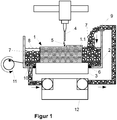
- the molded body 1 is, as in FIG. 1 shown in the space 2 on the printing platform 3 constructed in layers, by the metal wire 4 by means of the arc 5 dropwise metal melted and deposited in the production level 1.1.
- the liquid heat transfer fluid 8 is permanently introduced with the cooling granules 7 in the space 2; through the discharge 10, both are removed and cleaned (not shown) in the controllable cooling control device 12 with integrated granular cooling reservoir, cooled to a predetermined temperature and introduced again in the required amount via the feed 9 in the space 2.
- the space 2 is also connected to the vibrator 11, by means of which the filled via the feed 9 in the space 2 cooling granules 7 is evenly distributed and compacted.
- the decoupling elements 6 decouple the printing platform 3 from the vibrations.
- the dry cooling granules 7 is introduced via the feed 9 in the space 2, wherein the vibrator 11 ensures a uniform distribution with the greatest possible packing density.
- the liquid heat transfer fluid 8 is selectively sprayed by the nozzles 14 adjacent to the molded body 1 on the cooling granules 7, the same cools with evaporation of the heat transfer fluid 8.
Landscapes
- Engineering & Computer Science (AREA)
- Mechanical Engineering (AREA)
- Physics & Mathematics (AREA)
- Chemical & Material Sciences (AREA)
- Materials Engineering (AREA)
- Manufacturing & Machinery (AREA)
- Plasma & Fusion (AREA)
- Optics & Photonics (AREA)
- Powder Metallurgy (AREA)
Abstract
Description
- Die Erfindung betrifft ein Verfahren und eine Anlage zum Herstellen von metallischen Formkörpern mittels eines additiven Fertigungsverfahrens, bei welchem der schichtweise Aufbau durch Abschmelzen eines vorzugsweise drahtförmigen Werkstoffes erfolgt, wobei zum Zweck einer erhöhten Aufbaurate des Formkörpers während der Fertigung eine effektive Kühlung des im Aufbau befindlichen Formkörpers ermöglicht wird.
- Additiv-generative Fertigungsverfahren nehmen bereits heute eine bedeutende Stellung innerhalb der Fertigungstechnologien ein. Da bei generativen Fertigungsverfahren, wie dem selektiven Laserschmelzen (SLM) oder dem Auftragschweißen, der Werkstoff vor bzw. während des Abscheidens aufgeschmolzen wird, können sehr hohe Prozesstemperaturen auftreten. Dies trifft insbesondere auf die Verwendung metallischer Werkstoffe zu, bei denen die Schmelztemperaturen in der Regel bei etwa 1500°C liegen, wobei z. B. bei Verwendung eines Lichtbogens auch deutlich höhere Temperaturen erreicht werden können. Somit ist der limitierende Faktor in der Fertigungsgeschwindigkeit oftmals die Wärmeabfuhr aus den fertiggestellten Schichten des Formkörpers. Bei unzureichender Kühlung entsteht zum einen eine erhebliche Erwärmung des Gesamtsystems resultierend in veränderten Gefügeeigenschaften der abgeschiedenen Metallschichten und zum anderen tritt eine erhöhte Oxidationsneigung auf, die wiederum die Eigenschaften des generierten Bauteiles, insbesondere in den Randzonen, beeinflussen kann.
- Aus dem Stand der Technik ist bekannt, das Bauteil während seiner generativen Fertigung mittels eines Wärmeübertragungsfluids aktiv zu kühlen.
- Dies umfasst die Kühlung mit einem starken Gasstrom. Hierzu offenbart beispielsweise
DE 10 2013 022 056 A1 eine Vorrichtung zum Schweißen mittels Lichtbogens, die z. B. mit einer Ringdüse einen Kaltgasstrom um den Lichtbogen erzeugt, der denselben auch einschnürt. Nachteilig daran ist, dass Gase eine - z. B. im Vergleich zu Flüssigkeiten - nur geringe Wärmekapazität und damit Kühlvermögen aufweisen, sodass der Gasstrom für eine Kühlwirkung sehr stark sein muss, wobei er die Schutzgaswirkung bei der Schichtabscheidung oder sogar den Lichtbogen selbst stören kann. - Für eine effektivere Kühlung sind somit flüssige Wärmeübertragungsfluide zu bevorzugen, wobei der Formkörper beispielsweise mittels Eintauchens in eine Kühlflüssigkeit, wie in
US 2015/0108095 A1 beschrieben, oder mittels eines permanent strömenden Fluids, wie inDE 10 2007 009 273 A1 offenbart, temperiert wird. - Diese Lösungen zur Kühlung besitzen jedoch den Nachteil dass das gesamte Bauteil zum Schluss von Flüssigkeit umschlossen ist. Außerdem weist eine Wärmeabführung mittels einer Flüssigkeit den Nachteil auf, dass eine effektive Kühlung nur bei Temperaturen unterhalb der Verdampfungstemperatur der eingesetzten Flüssigkeit erfolgen kann, wobei auch bereits bei Temperaturen unterhalb der Verdampfungstemperatur das Auftreten von Siedebläschen (Dampfkavitation) an den Seitenwänden des Formkörpers die Wärmeabfuhr signifikant verschlechtern kann.
- Auch das aus anderen Verfahren (z. B. der mechanischen Bearbeitung) bekannte Aufspritzen von Flüssigkeiten zur Erzielung einer schnellen Abkühlung weist diese Nachteile auf. Hier kommt nachteilig hinzu, dass den nachfolgenden Schweißprozess störende Rückstände der aufgespritzten Flüssigkeiten auf der Oberfläche verbleiben.
- Weiterhin wird vorgeschlagen, mit einer gekühlten (verlorenen oder wiederverwendbaren) Druckplattform zu arbeiten. Hier ist der aufgrund der Kühlung des Bauteils nur von seiner mit der Druckplattform im thermischen Kontakt stehenden Wand bzw. Aufstandsfläche begrenzte Wärmeabtransport, der bei großen Bauteilen über sehr große Distanzen erfolgen muss, ein großer Nachteil.
- Aufgabe der Erfindung ist es, ein Verfahren und eine Vorrichtung zur additiv-generativen Fertigung eines metallischen Formkörpers zur Verfügung zu stellen, mittels deren eine effektive Kühlung des schichtweise aufzubauenden Formkörpers, insbesondere oberhalb von 1000°C, möglich und die Temperaturführung in einem weiten Temperaturbereich definiert steuerbar sein soll, sodass eine hohe Aufbaurate ermöglicht wird, d. h. ein Formkörper mit im Vergleich zum Stand der Technik verkürztem Zeitaufwand reproduzierbar hergestellt werden kann.
- Die Lösung dieser Aufgabe erfolgt durch ein Verfahren zur additiven Fertigung metallischer Formkörper gemäß dem Anspruch 1 sowie eine Anlage gemäß dem Anspruch 11. Zweckmäßige Weiterbildungen der Erfindung sind Gegenstand der Unteransprüche.
- Erfindungsgemäß wird ein additives Fertigungsverfahren zur Herstellung eines metallischen Formkörpers, vorzugsweise aus einem drahtförmigen, an der Drahtspitze unter Energiezufuhr abzuschmelzenden Werkstoff, bereitgestellt, wobei während der Herstellung eine Temperierung, umfassend die Kühlung mit einem festen, schüttfähigen Kühlmedium, der bereits fertiggestellten Teile des Formkörpers erfolgt. Der beispielsweise drahtförmige Werkstoff kann mittels einer Werkstoffzuführeinrichtung der Position, an welcher er abgeschmolzen wird, zugeführt werden. Die Energiezufuhr zum Abschmelzen kann mit einem Lichtbogen, einem Laser oder einem Elektronenstrahl erfolgen.
- Das feste, schüttfähige Kühlmedium wird im Folgenden als "Kühlgranulat" bezeichnet, wobei dieses Kühlgranulat aus einzelnen Granulatkörpern besteht.
- Die Granulatkörper des Kühlgranulats können alle dieselbe Geometrie und dieselbe Größe aufweisen. Zum Beispiel können Stahlkugeln als Granulatkörper eingesetzt sein. Vorzugsweise werden Granulatkörper mit unterschiedlichen Größen, vornehmlich in einem Bereich von 1 mm bis 10 mm, verwendet.
- Die Geometrie der Granulatkörper kann sphäroidisch, z. B. kugelförmig, sein. Bevorzugt werden jedoch Vielflächner, z. B. Oktaeder, eingesetzt, da derartige Granulatkörper sich gegenseitig bzw. die Seitenwände des Formkörpers flächig kontaktieren können und so (aufgrund der größeren Kontaktfläche) einen im Vergleich zu Kugeln höheren Wärmetransport erlauben.
- Die Granulatkörper bestehen zumindest an ihrer Oberfläche aus einem Material, welches gegenüber dem Werkstoff des herzustellenden Formkörpers inert ist. Bevorzugt weisen sie außerdem eine hohe Wärmeleitfähigkeit von z. B. mehr als 10 W m-1 K-1 auf.
- Um das Kühlgranulat universell während der Fertigung von Formkörpern aus beliebigen Werkstoffen einsetzen zu können, wird das Material, aus dem die Granulatkörper des Kühlgranulats bestehen, in der Regel unterschiedlich zu dem Werkstoff des zu fertigenden Formkörpers sein.
- Gemäß der Erfindung kann für die Temperierung, insbesondere die Kühlung, das Kühlgranulat in Verbindung mit einem flüssigen, fließfähigen oder gasförmigen Wärmeübertragungsfluid verwendet werden, wobei das Wärmeübertragungsfluid vorzugsweise wenig korrosiv und schwer entzündlich ist. Beispielsweise kann ein Schutzgas, ein Prozessgas oder eine kryogene Flüssigkeit (d. h. ein bei einer Temperatur unterhalb von -150°C verflüssigtes Gas) verwendet werden. Es kann jedoch auch vorgesehen sein, ein Gel, ein fließfähiges festes Kühlmittel, z. B. Kohlendioxidschnee, oder ein Aerosol als Wärmeübertragungsfluid einzusetzen.
- Im Folgenden werden alle Arten von Gas, welche geeignet sind, die Oxidation von schmelzflüssigem Metall zu verhindern (beispielsweise ein Edelgas wie Argon, ein Prozessgas wie Kohlendioxid oder ein Inertgas wie Stickstoff) als "Schutzgas" bezeichnet.
- Unter dem nachfolgend verwendeten Begriff "Fertigungsebene" ist diejenige Schicht des im (schichtweisen) Aufbau befindlichen Formkörpers zu verstehen, die gerade bearbeitet bzw. aufgebaut wird, d. h. in die unmittelbar der Wärmeeintrag durch die Energiezufuhr zum Aufschmelzen bzw. den schmelzflüssig aufgebrachten Werkstoff erfolgt.
- Nach Maßgabe der Erfindung werden also in einen Bauraum, in welchem der Formkörper hergestellt wird, das Kühlgranulat eingefüllt und gegebenenfalls das Wärmeübertragungsfluid eingeleitet. Hierbei wird der Bauraum nur teilweise mit Kühlgranulat gefüllt, wobei der obere Bereich des Formkörpers, d. h. die Fertigungsebene, aus der Kühlgranulatschüttung herausragt.
- Vorzugsweise wird die Höhe der Kühlgranulatschüttung auf wenige Millimeter (z. B. etwa 10 mm) unterhalb der Fertigungsebene eingestellt, wobei sie jedoch bevorzugt mindestens 50% der Höhe des bereits aufgebauten Formkörperteils beträgt.
- Mit dem sukzessiven Aufbau des Formkörpers wird sodann weiteres Kühlgranulat zugeschüttet, d. h. die bereits aufgebauten Teile des Formkörpers werden von dem Kühlgranulat umschlossen. Gemäß der Erfindung bleibt somit der Abstand in lotrechter Richtung zwischen Oberkante der Kühlgranulatschüttung und Fertigungsebene während der Fertigung weitestgehend konstant.
- Der Vorteil der Kühlung unter Verwendung von Kühlgranulat ist die aufgrund der hohen Wärmeleitfähigkeit des Kühlgranulats beschleunigte Wärmeabfuhr aus dem Formkörper, d. h., die pro Zeiteinheit aus dem Formkörper abführbare Wärmemenge kann gegenüber Kühlung mit Gas um wenigstens zwei Größenordnungen gesteigert werden. Hierbei bleibt das Kühlgranulat auch bei Prozesstemperaturen weit über 1000°C voll "funktionsfähig", d. h., seine Kühlleistung ist nicht, wie z. B. aufgrund von Dampfkavitation bei flüssigen Kühlmitteln, eingeschränkt.
- Gemäß einer Ausgestaltung der Erfindung bestehen die Granulatkörper aus wenigstens zwei unterschiedlichen Materialien, wobei ein Kern aus einem Material mit einer hohen spezifischen Wärmekapazität von z. B. mehr als 2 kJ·kg-1·K-1 von einer Ummantelung aus einem Material mit einer hohen Wärmeleitfähigkeit von bevorzugt mehr als 10 W m-1 K-1 umhüllt ist.
- Die Ummantelung kann weiterhin mit einem Material beschichtet sein, welches inert ist gegenüber dem Werkstoff des Formkörpers und dem Wärmeübertragungsfluid, welches die Granulatkörper umgibt. Weiterhin kann das Beschichtungsmaterial elastisch verformbar sein und einen geringen Reibkoeffizienten aufweisen.
- In einer weiteren Ausgestaltung werden Granulatkörper mit einem Kern aus einem Phasenwechselmaterial (d. h. einem Material, das seinen Phasenzustand bei einer materialspezifischen Phasenübergangstemperatur unter Aufnahme bzw. Abgabe von latenter Wärme ändert) verwendet, wobei das Phasenwechselmaterial eine Phasenübergangstemperatur aufweist, die kleiner oder gleich der während der additiven Fertigung einzuhaltenden Bearbeitungstemperatur ist.
- Weiterhin kann vorgesehen sein, dass das Wärmeübertragungsfluid mit dem Kühlgranulat während der additiven Fertigung in vorgegebenen (periodischen oder aperiodischen) Zeitabständen oder fortwährend ausgetauscht wird. Dies ist insbesondere bei Verwendung von Granulatkörpern mit einem Phasenwechselmaterial von Vorteil, da das Phasenwechselmaterial nach Entnahme der Granulatkörper aus dem für die Fertigung verwendeten Bauraum regeneriert werden kann, d. h. das Phasenwechselmaterial mittels Kühlung seinen Phasenzustand unter Abgabe der im Bauraum aufgenommenen Wärmemenge wieder ändert.
- Ferner kann die Erfindung derart ausgestaltet sein, dass das Kühlgranulat weitestgehend unbewegt den Formkörper (zumindest teilweise) umgibt, während das (flüssige oder gasförmige) Wärmeübertragungsfluid durch das Kühlgranulat strömt und hierbei die durch das Kühlgranulat vom Formkörper abgeführte Wärme aufnimmt und aus dem Bauraum abführt.
- Gemäß einer weiteren Ausgestaltung wird fließfähiges Wärmeübertragungsfluid auf das Kühlgranulat gesprüht bzw. das Kühlgranulat mit dem Wärmeübertragungsfluid berieselt, wobei das Wärmeübertragungsfluid unter Aufnahme von latenter Wärme verdampft bzw. sublimiert. Das entstandene Gas wird sodann abgeführt und kann ggf. durch Kühlung wieder verflüssigt bzw. verfestigt werden.
- Auch kann vorgesehen sein, Kühlgranulat aus wenigstens zwei unterschiedlichen Materialien zu verwenden, wovon ein Material ein mit dem Ausgangswerkstoff des Formkörpers reagierender Zusatz- bzw. Schweißhilfsstoff, zum Beispiel Kohlenstoff, ist, sodass eine Oberflächenbeeinflussung des herzustellenden Formkörpers ermöglicht ist.
- Die Erfindung ist anwendbar auf bekannte additive Verfahren (wie z. B. Auftragschweißen unter Verwendung eines Lasers oder eines Lichtbogens, formgebendes Schweißen, US-Schweißen etc.), mittels der einzelne Schichten durch Abscheiden schmelzflüssiger Werkstoffe erzeugt werden können, wobei das schichtweise Aufbauen aus einem metallischen Werkstoff nicht auf diese Arten des additiven Fertigens eingeschränkt ist.
- Zur Durchführung des Verfahrens wird eine Anlage zur additiven Fertigung, im Folgenden Fertigungsanlage genannt, verwendet, die einen Bauraum und eine Werkstoffzuführeinrichtung zur Zuführung z. B. eines Schweißdrahtes umfasst.
- Der Bauraum ist bevorzugt wannen- oder kastenförmigen, wobei er nach oben hin offen oder auch vollständig abgeschlossenen (d. h., der Bauraum ist gegen die Umgebung abgedichtet) sein kann. Weiterhin kann vorgesehen sein, dass in dem Bauraum eine Schutzgasatmosphäre herrscht.
- Die Fertigungsanlage umfasst weiterhin eine in dem Bauraum angeordnete Druckplattform, auf welcher der Formkörper aufgebaut wird, wobei vorgesehen sein kann, dass die Druckplattform nach Fertigstellung jeweils einer Schicht um die Höhe dieser Schicht in vertikaler Richtung nach unten bewegt wird. Es kann auch vorgesehen sein, dass die Werkstoffzuführeinrichtung der Fertigungsanlage entsprechend des schichtweisen Wachsens des Formkörpers in der Höhe nachgeführt wird, während die Druckplattform unbewegt ist.
- Erfindungsgemäß werden in den Bauraum, in welchem der Formkörper hergestellt wird, das Kühlgranulat und das Wärmeübertragungsfluid eingeleitet. Um das Kühlgranulat mit dem sukzessiven Aufbau des Formkörpers jeweils hinzuschütten zu können, weist die Fertigungsanlage eine steuerbare Kühlgranulat-Zuführung und einen mit dieser verbundenen Kühlgranulat-Vorratsbehälter auf.
- Die Fertigungsanlage umfasst weiterhin eine vorzugsweise mit der Bodenplatte des Bauraumes verbundene Rüttelvorrichtung, mittels welcher der gesamte Bauraum oder nur dessen Bodenplatte in Vibration versetzbar ist. Somit kann durch permanentes oder in periodischen Abständen durchgeführtes Rütteln die Kühlgranulatschüttung kompaktiert werden, d. h. die Kontaktbereiche zwischen den einzelnen Granulatkörpern vergrößert werden.
- Zur Entkoppelung eines zu fertigenden Formkörpers von der Rüttelvorrichtung ist vorzugsweise zumindest die Druckplattform mittels eines oder mehrerer Entkopplungs-Elemente von der Bodenplatte des Bauraumes vibrationstechnisch abgehängt.
- Um das (flüssige oder gasförmige) Wärmeübertragungsfluid durch den Bauraum strömen zu lassen, können die Wandungen des Bauraums Wärmeübertragungsfluid-Eintrittsöffnungen, durch welche das Wärmeübertragungsfluid in den Bauraum eintritt, und Wärmeübertragungsfluid-Austrittsöffnungen, durch welche das Wärmeübertragungsfluid aus dem Bauraum heraustritt, aufweisen. Es kann aber auch vorgesehen sein, eine oder mehrere Wärmeübertragungsfluid-Zuführleitungen von oben in den (z. B. nach oben offenen Bauraum) einzuführen. An den Eintritts- und Austrittsöffnungen für das Wärmeübertragungsfluid können einzeln ansteuerbare Ventile zum Öffnen bzw. Schließen der Öffnungen vorgesehen sein.
- Ebenso können im Bodenbereich des Bauraums Fluid-Austrittsöffnungen eingebracht sein, durch welche das Wärmeübertragungsfluid und/oder bei der Fertigung entstehende Gase oder Schweißrauch abgesaugt werden.
- Die Wärmeübertragungsfluid-Eintrittsöffnungen und insbesondere die Austrittsöffnungen können hierbei Filter oder Membranen aufweisen, die nur das Wärmeübertragungsfluid passieren lassen.
- Gemäß einer Ausgestaltung können in den Wänden, der Decke und/oder den Boden des Bauraumes eingebrachte Eintrittsöffnungen und Austrittsöffnungen sowohl durchlässig für das Wärmeübertragungsfluid als auch durchlässig für das Kühlgranulat gestaltet sein, sodass sowohl das Wärmeübertragungsfluid durch den Bauraum strömt, als auch das Kühlgranulat (kontinuierlich oder in vorgegebenen Zeitabständen) in den Bauraum einbringbar bzw. aus dem Bauraum herausführbar, d. h. austauschbar, ist.
- Der Bauraum kann aber auch nur für das Kühlgranulat vorgesehene Austrittsöffnungen aufweisen, wobei die Fertigungsanlage z. B. eine Kühlgranulat-Abfuhreinrichtung umfasst.
- Mittels entsprechender Leitungen kann hierbei ein geschlossener Wärmeübertragungsfluid- und/oder Kühlgranulat-Kreislauf realisiert werden, wobei das Wärmeübertragungsfluid bzw. das Kühlgranulat außerhalb des Bauraums temperiert und/oder gereinigt wird
- Weiterhin kann vorgesehen sein, dass im oberen Bereich des Bauraumes eine steuerbare Fluidzuführungseinrichtung mit Wärmeübertragungsfluidleitungen, aufweisend Austrittsöffnungen oder Düsen, durch welche das Wärmeübertragungsfluid (von oben) auf das Kühlgranulat verteilbar ist, angeordnet ist. Hierbei kann durch eine entsprechende Anordnung der Austrittsöffnungen oder Düsen eine Anströmung der Kühlgranulatschüttung durch das Wärmeübertragungsfluid punktuell, partiell oder großflächig durchführbar sein.
- Insbesondere kann vorgesehen sein, dass jede der Austrittsöffnungen oder Düsen mittels eines jeweils einzeln ansteuerbaren Ventiles oder Massestromkontrollers regelbar geöffnet oder geschlossen werden kann. So ist es z. B. möglich, nur jeweils aus derjenigen Düse Kühlmittel strömen zu lassen, die aufgrund ihrer Positionierung und Ausrichtung das Wärmeübertragungsfluid auf das Kühlgranulat (und nicht den Formkörper) sprüht.
- Die Ansteuerung der Fluidzuführungseinrichtung, d. h. die konkrete Festlegung des mit dem Fluid zu bestrahlenden Oberflächenbereiches sowie der aus den Düsen ausströmende Fluidmassestrom, erfolgt z. B. bahngeneriert, d. h., Fluidmassestrom sowie Form und Position des zu bestrahlenden Oberflächenbereiches werden aufgrund der bei der Fertigung programmierten Bahn des Generierwirkortes innerhalb der lagenweise aufzubauenden Schichten festgelegt.
- Es kann auch vorgesehen sein, dass die Fluidzuführungseinrichtung sowohl ein fließfähiges Wärmeübertragungsfluid als auch ein Prozess- oder Schutzgas zuführen kann, wobei während des Betriebes der Fertigungsanlage aus der Fluidzuführungseinrichtung sowohl das Wärmeübertragungsfluid als auch das Gas strömt, d. h., aus einem Teil der Düsen strömt Wärmeübertragungsfluid und aus dem restlichen Teil der Düsen strömt Prozess- oder Schutzgas. Hierfür kann jede der Düsen mit einem jeweils einzeln ansteuerbaren Umschaltventil verbunden sein, wobei die Umschaltventile jeweils mit einer Wärmeübertragungsfluidzufuhrleitung und einer Prozess- bzw. Schutzgaszufuhrleitung verbunden sind. So kann der Formkörper selektiv mit Schutzgas angeströmt werden, während das den Formkörper umgebende Kühlgranulat mit dem Wärmeübertragungsfluid besprüht wird.
- Die Erfindung kann weiter derart ausgebildet sein, dass die Fertigungsanlage eine Absaugvorrichtung, z. B. in Form eines Saugrüssels, umfasst, mittels derer das verdampfte oder sublimierte Wärmeübertragungsfluid auffangbar ist, um es beispielsweise (nach Reinigung und/oder Abkühlung) erneut zur Kühlung zu verwenden.
- Die Erfindung wird nachfolgend anhand von Ausführungsbeispielen näher erläutert, wobei gleiche oder ähnliche Merkmale mit gleichen Bezugszeichen versehen sind. Dazu zeigen in schematischer Darstellung die
-
Figur 1 : eine erste Ausgestaltungsvariante der Fertigungsanlage; und -
Figur 2 : eine zweite Ausgestaltungsvariante der Fertigungsanlage. - Der Formkörper 1 wird, wie in
Figur 1 gezeigt, in dem Bauraum 2 auf der Druckplattform 3 schichtweise aufgebaut, indem von dem Metalldraht 4 mittels des Lichtbogens 5 tröpfchenweise Metall abgeschmolzen und in der Fertigungsebene 1.1 abgeschieden wird. - In den Bauraum 2 ist eine Mischung aus dem Kühlgranulat 7 und dem flüssigen Wärmeübertragungsfluid 8 eingefüllt, wobei die Fertigungsebene 1.1 des Formkörpers 1 aus dem flüssigen Wärmeübertragungsfluid 8 bzw. dem Kühlgranulat 7 herausragt, d. h. unbedeckt bleibt.
- Durch die Zuführung 9 wird permanent das flüssige Wärmeübertragungsfluid 8 mit dem Kühlgranulat 7 in den Bauraum 2 eingeführt; durch die Abführung 10 werden beide entnommen und in der steuerbaren Kühlregeleinrichtung 12 mit integriertem Kühlgranulat-Vorratsbehälter (nicht dargestellt) gereinigt, auf eine vorgegebene Temperatur abgekühlt und in der benötigten Menge wieder über die Zuführung 9 in den Bauraum 2 eingeleitet.
- Der Bauraum 2 ist außerdem mit der Rütteleinrichtung 11 verbunden, mittels der das über die Zuführung 9 in den Bauraum 2 eingefüllte Kühlgranulat 7 gleichmäßig verteilbar und kompaktierbar ist. Die Entkopplungs-Elemente 6 entkoppeln die Druckplattform 3 von den Vibrationen.
- Gemäß der in
Figur 2 dargestellten Variante der Fertigungsanlage wird das trockene Kühlgranulat 7 über die Zuführung 9 in den Bauraum 2 eingeführt, wobei die Rütteleinrichtung 11 für eine gleichmäßige Verteilung bei größtmöglicher Packungsdichte sorgt. - Mittels der Wärmeübertragungsfluid-Zuführungseinrichtung 13 wird das flüssige Wärmeübertragungsfluid 8 durch die Düsen 14 gezielt neben den Formkörper 1 auf das Kühlgranulat 7 gesprüht, wobei selbiges unter Verdampfung des Wärmeübertragungsfluids 8 abkühlt.
-
- 1
- Formkörper
- 1.1
- Fertigungsebene
- 2
- Bauraum
- 3
- Druckplattform
- 4
- Metalldraht / Ausgangswerkstoff
- 5
- Lichtbogen
- 6
- Entkopplungs-Element
- 7
- Kühlgranulat
- 8
- Wärmeübertragungsfluid
- 9
- Zuführung
- 10
- Abführung
- 11
- Rütteleinrichtung
- 12
- Kühlregeleinrichtung
- 13
- Wärmeübertragungsfluid-Zuführungseinrichtung
- 14
- Düse
Claims (13)
- Verfahren zur additiven Fertigung metallischer Formkörper, wobei in einem Bauraum (2) ein Formkörper (1) durch Aufschmelzen von mindestens einem mittels einer Werkstoffzuführeinrichtung zugeführten Ausgangswerkstoff (4) mittels Energiezufuhr und Abscheiden des schmelzförmigen Ausgangswerkstoffs (4) in einzelnen aufeinanderfolgenden Schichten hergestellt wird,
dadurch gekennzeichnet, dass
die während des Abscheidens entstehende Prozesswärme mittels eines die bereits fertiggestellten Teile des Formkörpers (1) zumindest teilweise umschließenden und kontaktierenden, schüttfähigen Kühlgranulats (7) abgeführt wird. - Verfahren nach Anspruch 1, dadurch gekennzeichnet, dass die von dem Kühlgranulats (7) aufgenommene Prozesswärme mittels eines mit dem Kühlgranulat (7) in thermischer Wechselwirkung stehenden Wärmeübertragungsfluids (8) abgeführt wird.
- Verfahren nach Anspruch 2, dadurch gekennzeichnet, dass das Wärmeübertragungsfluid (8) vor dem Einleiten in den Bauraum (2) temperiert wird.
- Verfahren nach einem der Ansprüche 2 oder 3, dadurch gekennzeichnet, dass das Kühlgranulat (7) während der Fertigung von dem Wärmeübertragungsfluid (8) durchströmt wird.
- Verfahren nach einem der vorstehenden Ansprüche, dadurch gekennzeichnet, dass das im Bauraum (2) befindliche Kühlgranulat (7) kontinuierlich oder in vorgegebenen Zeitabständen ausgetauscht wird.
- Verfahren nach einem der vorstehenden Ansprüche, dadurch gekennzeichnet, dass Kühlgranulat (7) mit Granulatkörpern mit einem Granulatkörperkern aus Phasenwechselmaterial und einer Granulatkörperummantelung aus einem metallischen oder keramischen Werkstoff mit einer Wärmeleitfähigkeit von
wenigstens 10 W m-1 K-1 verwendet wird. - Verfahren nach einem der Ansprüche 2 bis 6, dadurch gekennzeichnet, dass gasförmiges Wärmeübertragungsfluid (8) verwendet wird, wobei dieses im unteren Bereich des Bauraumes (2) in denselben eingeleitet wird und das Kühlgranulat (7) von unten nach oben durchströmt.
- Verfahren nach einem der vorstehenden Ansprüche 2 bis 6, dadurch gekennzeichnet, dass im unteren Bereich des Bauraumes (2) eine Absaugung von durch das Kühlgranulat (7) strömenden Gasen erfolgt.
- Verfahren nach einem der vorstehenden Ansprüche, dadurch gekennzeichnet, dass Kühlgranulat (7) mit mindestens zwei Arten von Granulatkörpern verwendet wird, wovon eine aus einem Schweißhilfsstoff besteht.
- Verfahren nach einem der vorstehenden Ansprüche, dadurch gekennzeichnet, dass Kühlgranulat (7) mit Granulatkörpern unterschiedlicher Korngrößen und/oder unterschiedlicher geometrischer Formen verwendet wird.
- Anlage zur additiven Fertigung metallischer Formkörper (1) durch Abscheiden eines schmelzbaren blech-, draht- oder pulverförmigen Ausgangswerkstoffes (4) in einzelnen, jeweils aufeinanderfolgenden Schichten gemäß des Verfahrens nach einem der vorstehenden Ansprüche, aufweisend einen kasten- oder wannenförmigen Bauraum (2) und eine darin angeordnete Druckplattform (3), dadurch gekennzeichnet, dass die Anlage eine Zuführung (9) zum Einfüllen von festem, schüttbarem Kühlgranulat (7) in den Bauraum (2) und eine mit wenigstens der Bodenplatte des Bauraumes (2) verbundene Rütteleinrichtung (11) umfasst, wobei die Druckplattform (3) mittels eines oder mehrerer Entkopplungs-Elemente (6) von der Rütteleinrichtung (11) entkoppelt ist.
- Anlage nach Anspruch 11, dadurch gekennzeichnet, dass sie eine Wärmeübertragungsfluid-Zuführungseinrichtung (13) mit Durchflussreglern und Düsen (14) umfasst, mittels welcher das Kühlgranulat (7) mit Wärmeübertragungsfluid (8) beaufschlagbar ist, wobei für jede Düse (14) ein durch sie strömender Fluidmassestrom jeweils mittels eines Masseflussreglers separat steuerbar ist.
- Anlage nach Anspruch 12, dadurch gekennzeichnet, dass jede der Düsen (14) mittels eines Umschaltventils und/oder Mischers jeweils mit einer Zuleitung für Schutzgas und einer Zuleitung für flüssiges Wärmeübertragungsfluid (8) verbunden ist.
Priority Applications (1)
| Application Number | Priority Date | Filing Date | Title |
|---|---|---|---|
| PL17160904T PL3222373T3 (pl) | 2016-03-21 | 2017-03-14 | Sposób i urządzenie do wytwarzania addytywnego metalowych elementów kształtowych |
Applications Claiming Priority (1)
| Application Number | Priority Date | Filing Date | Title |
|---|---|---|---|
| DE102016105162.4A DE102016105162A1 (de) | 2016-03-21 | 2016-03-21 | Verfahren und Anlage zur additiven Fertigung metallischer Formkörper |
Publications (2)
| Publication Number | Publication Date |
|---|---|
| EP3222373A1 true EP3222373A1 (de) | 2017-09-27 |
| EP3222373B1 EP3222373B1 (de) | 2019-01-09 |
Family
ID=58387629
Family Applications (1)
| Application Number | Title | Priority Date | Filing Date |
|---|---|---|---|
| EP17160904.3A Not-in-force EP3222373B1 (de) | 2016-03-21 | 2017-03-14 | Verfahren und anlage zur additiven fertigung metallischer formkörper |
Country Status (4)
| Country | Link |
|---|---|
| EP (1) | EP3222373B1 (de) |
| DE (1) | DE102016105162A1 (de) |
| ES (1) | ES2718414T3 (de) |
| PL (1) | PL3222373T3 (de) |
Cited By (8)
| Publication number | Priority date | Publication date | Assignee | Title |
|---|---|---|---|---|
| CN107598335A (zh) * | 2017-11-13 | 2018-01-19 | 山东建筑大学 | 一种实现丝材电弧熔铸增材制造的装置 |
| CN107803568A (zh) * | 2017-11-13 | 2018-03-16 | 山东建筑大学 | 一种提高丝材电弧增材制造精度及成形效率的方法 |
| CN108994426A (zh) * | 2018-09-06 | 2018-12-14 | 西南交通大学 | 金属构件电弧填丝增材制造实时降温装置与方法 |
| CN109604808A (zh) * | 2018-12-11 | 2019-04-12 | 东北大学 | 一种施加冷却的搅拌摩擦增材制造装置及方法 |
| JP2019081187A (ja) * | 2017-10-30 | 2019-05-30 | 株式会社神戸製鋼所 | 積層造形物の製造方法 |
| EP3549708A1 (de) * | 2018-04-06 | 2019-10-09 | Linde Aktiengesellschaft | Homogene kühlung für schweissverfahren, insbesondere waam |
| CN116423036A (zh) * | 2023-05-22 | 2023-07-14 | 南京航空航天大学 | 一种复杂构件搅拌摩擦增材制造精准冷却控温装置及方法 |
| CN118060676A (zh) * | 2024-04-22 | 2024-05-24 | 烟台大学 | 一种高温合金稀土元素增材制造装备及方法 |
Families Citing this family (6)
| Publication number | Priority date | Publication date | Assignee | Title |
|---|---|---|---|---|
| DE102017200945B3 (de) * | 2017-01-20 | 2018-05-09 | Ford Global Technologies, Llc | Verfahren zur Herstellung von Hybrid- Leichtbau- Bremsscheiben |
| DE102017220763A1 (de) * | 2017-11-21 | 2019-05-23 | Siemens Aktiengesellschaft | Auftragschweißen mit pulverförmigem Zusatzwerkstoff unter Wasser |
| DE102018210397A1 (de) * | 2018-06-26 | 2020-01-02 | Siemens Aktiengesellschaft | Verfahren zur additiven Herstellung einer Struktur mit Kühlmittelführung, Bauteil und Vorrichtung |
| CN111185694B (zh) * | 2020-02-14 | 2022-01-07 | 荆门宏图特种飞行器制造有限公司 | 管板堆焊机及其防变形装置、堆焊方法 |
| CN113695573B (zh) * | 2020-05-07 | 2023-05-02 | 昆山晶微新材料研究院有限公司 | 一种用于液态金属3d打印的连续供液打印系统及方法 |
| DE102021205815A1 (de) | 2021-06-09 | 2022-12-15 | Siemens Energy Global GmbH & Co. KG | Konvektionskühler für Wire Arc Additiv Manufacturing |
Citations (8)
| Publication number | Priority date | Publication date | Assignee | Title |
|---|---|---|---|---|
| EP1316408A1 (de) * | 2001-11-28 | 2003-06-04 | Concept Laser GmbH | Vorrichtung zum Herstellen und/oder Bearbeiten von Bauteilen aus Pulverteilchen |
| EP1669143A1 (de) * | 2004-12-07 | 2006-06-14 | 3D Systems, Inc. | Verfahren zum kontrollierten Kühlen eines lasergesinterten Pulvergegenstandes und Vorrichtung dafür |
| DE102007009273A1 (de) | 2007-02-26 | 2007-08-16 | Daimlerchrysler Ag | Verfahren und Vorrichtung zur Herstellung eines dreidimensionalen Gegenstandes aus einem verfestigbaren Material |
| US20110165339A1 (en) * | 2008-09-05 | 2011-07-07 | Peter Skoglund | Method of producing objects containing nano metal or composite metal |
| CN104399978A (zh) * | 2014-11-27 | 2015-03-11 | 华南理工大学 | 一种大尺寸复杂形状多孔非晶合金零件的3d成形方法 |
| US20150108095A1 (en) | 2013-10-18 | 2015-04-23 | +Mfg, LLC | Method and apparatus for fabrication of articles by molten and semi-molten deposition |
| DE102013022056A1 (de) | 2013-12-23 | 2015-06-25 | Christian Bürkner | Verfahren und Vorrichtung zur Konditionierung eines Schweiß- oder Schneidprozesses |
| EP2992986A1 (de) * | 2014-09-03 | 2016-03-09 | SLM Solutions Group AG | Vorrichtung zur Herstellung von 3D-Werkstücken durch schichtweises Aufbauverfahren mit einer Trockenvorrichtung |
Family Cites Families (3)
| Publication number | Priority date | Publication date | Assignee | Title |
|---|---|---|---|---|
| SE530323C2 (sv) * | 2006-09-26 | 2008-05-06 | Foersvarets Materielverk | Sätt att framställa föremål av amorf metall |
| EP2286982B1 (de) * | 2009-08-20 | 2013-09-25 | Matthias Fockele | Vorrichtung zur Herstellung von Formkörpern durch schichtweises Aufbauen aus Werkstoffpulver |
| DE102012216515A1 (de) * | 2012-09-17 | 2014-03-20 | Evonik Industries Ag | Verfahren zur schichtweisen Herstellung von verzugsarmen dreidimensionalen Objekten mittels Kühlelementen |
-
2016
- 2016-03-21 DE DE102016105162.4A patent/DE102016105162A1/de not_active Withdrawn
-
2017
- 2017-03-14 ES ES17160904T patent/ES2718414T3/es active Active
- 2017-03-14 PL PL17160904T patent/PL3222373T3/pl unknown
- 2017-03-14 EP EP17160904.3A patent/EP3222373B1/de not_active Not-in-force
Patent Citations (8)
| Publication number | Priority date | Publication date | Assignee | Title |
|---|---|---|---|---|
| EP1316408A1 (de) * | 2001-11-28 | 2003-06-04 | Concept Laser GmbH | Vorrichtung zum Herstellen und/oder Bearbeiten von Bauteilen aus Pulverteilchen |
| EP1669143A1 (de) * | 2004-12-07 | 2006-06-14 | 3D Systems, Inc. | Verfahren zum kontrollierten Kühlen eines lasergesinterten Pulvergegenstandes und Vorrichtung dafür |
| DE102007009273A1 (de) | 2007-02-26 | 2007-08-16 | Daimlerchrysler Ag | Verfahren und Vorrichtung zur Herstellung eines dreidimensionalen Gegenstandes aus einem verfestigbaren Material |
| US20110165339A1 (en) * | 2008-09-05 | 2011-07-07 | Peter Skoglund | Method of producing objects containing nano metal or composite metal |
| US20150108095A1 (en) | 2013-10-18 | 2015-04-23 | +Mfg, LLC | Method and apparatus for fabrication of articles by molten and semi-molten deposition |
| DE102013022056A1 (de) | 2013-12-23 | 2015-06-25 | Christian Bürkner | Verfahren und Vorrichtung zur Konditionierung eines Schweiß- oder Schneidprozesses |
| EP2992986A1 (de) * | 2014-09-03 | 2016-03-09 | SLM Solutions Group AG | Vorrichtung zur Herstellung von 3D-Werkstücken durch schichtweises Aufbauverfahren mit einer Trockenvorrichtung |
| CN104399978A (zh) * | 2014-11-27 | 2015-03-11 | 华南理工大学 | 一种大尺寸复杂形状多孔非晶合金零件的3d成形方法 |
Cited By (12)
| Publication number | Priority date | Publication date | Assignee | Title |
|---|---|---|---|---|
| JP2019081187A (ja) * | 2017-10-30 | 2019-05-30 | 株式会社神戸製鋼所 | 積層造形物の製造方法 |
| CN107598335A (zh) * | 2017-11-13 | 2018-01-19 | 山东建筑大学 | 一种实现丝材电弧熔铸增材制造的装置 |
| CN107803568A (zh) * | 2017-11-13 | 2018-03-16 | 山东建筑大学 | 一种提高丝材电弧增材制造精度及成形效率的方法 |
| EP3549708A1 (de) * | 2018-04-06 | 2019-10-09 | Linde Aktiengesellschaft | Homogene kühlung für schweissverfahren, insbesondere waam |
| WO2019192755A1 (de) * | 2018-04-06 | 2019-10-10 | Linde Aktiengesellschaft | Homogene kühlung für schweissverfahren, insbesondere waam |
| CN111936258A (zh) * | 2018-04-06 | 2020-11-13 | 林德有限责任公司 | 用于焊接工艺,特别是电弧增材制造工艺的均匀冷却装置 |
| CN108994426A (zh) * | 2018-09-06 | 2018-12-14 | 西南交通大学 | 金属构件电弧填丝增材制造实时降温装置与方法 |
| CN109604808A (zh) * | 2018-12-11 | 2019-04-12 | 东北大学 | 一种施加冷却的搅拌摩擦增材制造装置及方法 |
| CN109604808B (zh) * | 2018-12-11 | 2020-10-09 | 东北大学 | 一种施加冷却的搅拌摩擦增材制造装置及方法 |
| CN116423036A (zh) * | 2023-05-22 | 2023-07-14 | 南京航空航天大学 | 一种复杂构件搅拌摩擦增材制造精准冷却控温装置及方法 |
| CN116423036B (zh) * | 2023-05-22 | 2026-01-30 | 南京航空航天大学 | 一种复杂构件搅拌摩擦增材制造精准冷却控温装置及方法 |
| CN118060676A (zh) * | 2024-04-22 | 2024-05-24 | 烟台大学 | 一种高温合金稀土元素增材制造装备及方法 |
Also Published As
| Publication number | Publication date |
|---|---|
| PL3222373T3 (pl) | 2019-08-30 |
| EP3222373B1 (de) | 2019-01-09 |
| DE102016105162A1 (de) | 2017-09-21 |
| ES2718414T3 (es) | 2019-07-01 |
Similar Documents
| Publication | Publication Date | Title |
|---|---|---|
| EP3222373B1 (de) | Verfahren und anlage zur additiven fertigung metallischer formkörper | |
| EP3359320B1 (de) | Bearbeitungsmodul für eine vorrichtung zur additiven fertigung und verwendung dieses bearbeitungsmoduls zur additiven fertigung eines formkörpers | |
| DE102015113792B4 (de) | Laserbasiertes additives fertigungsverfahren | |
| EP3069816B1 (de) | Verfahren und anlage zur additiven fertigung unter verwendung eines drahtförmigen werkstoffs | |
| DE69229707T2 (de) | Kontrolliertes Verfahren zur Erzeugung eines pulverisierten Metalltropfenstrahls | |
| EP2340925B1 (de) | Verfahren zum generativen Herstellen eines dreidimensionalen Objekts mit kontinuierlicher Wärmezufuhr | |
| DE102007009273B4 (de) | Verfahren und Vorrichtung zur Herstellung eines dreidimensionalen Gegenstandes aus einem verfestigbaren Material | |
| DE102015115963B4 (de) | Verfahren zur additiven Fertigung eines Formkörpers aus einem metallischen Werkstoffgemisch | |
| EP3219413A1 (de) | Verfahren und vorrichtung zum generativen fertigen eines dreidimensionalen bauteils | |
| EP3579998B1 (de) | Erhöhung der oberflächenqualität | |
| DE102015108131A1 (de) | Verfahren und Vorrichtung zur additiven Fertigung | |
| DE69202728T2 (de) | Metallische spritzung mittels mehrerer düsen. | |
| EP3069804B1 (de) | Verfahren zur additiven fertigung eines formkörpers | |
| DE3730147A1 (de) | Verfahren zur herstellung von pulvern aus geschmolzenen stoffen | |
| DE102017211381A1 (de) | Verfahren zum Abkühlen und Abkühlvorrichtung | |
| DE3942049A1 (de) | Verfahren und vorrichtung zum erzeugen von einspeisungsmaterialstroemen mittels transversallaserstrahlduesen | |
| DE102007057450A1 (de) | Verfahren und Vorrichtung zur Herstellung eines dreidimensionalen Gegenstandes aus einem verfestigbaren Material | |
| EP4065344B1 (de) | Verfahren und vorrichtung zum herstellen von 3d-formteilen mittels hochleistungsstrahler | |
| DE102021103870A1 (de) | Additive fertigung mit drehbarem abscheidekopf | |
| EP2708348A1 (de) | Verfahren und Vorrichtung zur schichtweisen Herstellung von verzugsarmen dreidimensionalen Objekten mittels Kühlelementen | |
| EP3228407B1 (de) | Arbeitstisch für die additive fertigung | |
| WO2023209107A1 (de) | Filtersystem mit individuell abtrennbaren filterkammern | |
| EP3219415A1 (de) | Verfahren und vorrichtung zum generativen fertigen eines dreidimensionalen bauteils | |
| DE3231316A1 (de) | Verfahren und vorrichtung zur steuerung des abgiessens einer schmelze aus einem schmelzenbehaelter mit einer bodenoeffnung | |
| DE602005000770T2 (de) | Verfahren und Einrichtung zum Recycling von Inertgasen |
Legal Events
| Date | Code | Title | Description |
|---|---|---|---|
| PUAI | Public reference made under article 153(3) epc to a published international application that has entered the european phase |
Free format text: ORIGINAL CODE: 0009012 |
|
| STAA | Information on the status of an ep patent application or granted ep patent |
Free format text: STATUS: THE APPLICATION HAS BEEN PUBLISHED |
|
| AK | Designated contracting states |
Kind code of ref document: A1 Designated state(s): AL AT BE BG CH CY CZ DE DK EE ES FI FR GB GR HR HU IE IS IT LI LT LU LV MC MK MT NL NO PL PT RO RS SE SI SK SM TR |
|
| AX | Request for extension of the european patent |
Extension state: BA ME |
|
| STAA | Information on the status of an ep patent application or granted ep patent |
Free format text: STATUS: REQUEST FOR EXAMINATION WAS MADE |
|
| 17P | Request for examination filed |
Effective date: 20180314 |
|
| RBV | Designated contracting states (corrected) |
Designated state(s): AL AT BE BG CH CY CZ DE DK EE ES FI FR GB GR HR HU IE IS IT LI LT LU LV MC MK MT NL NO PL PT RO RS SE SI SK SM TR |
|
| GRAP | Despatch of communication of intention to grant a patent |
Free format text: ORIGINAL CODE: EPIDOSNIGR1 |
|
| STAA | Information on the status of an ep patent application or granted ep patent |
Free format text: STATUS: GRANT OF PATENT IS INTENDED |
|
| RIC1 | Information provided on ipc code assigned before grant |
Ipc: B33Y 30/00 20150101ALI20180709BHEP Ipc: B23K 26/12 20140101ALI20180709BHEP Ipc: B33Y 10/00 20150101ALI20180709BHEP Ipc: B29C 64/245 20170101ALI20180709BHEP Ipc: B23K 26/00 20140101ALI20180709BHEP Ipc: B23K 26/70 20140101ALI20180709BHEP Ipc: B29C 64/153 20170101ALI20180709BHEP Ipc: B23K 9/32 20060101ALI20180709BHEP Ipc: B29C 64/25 20170101ALN20180709BHEP Ipc: B23K 9/04 20060101ALI20180709BHEP Ipc: B23K 9/23 20060101ALI20180709BHEP Ipc: B33Y 40/00 20150101ALI20180709BHEP Ipc: B23K 26/122 20140101ALI20180709BHEP Ipc: B22F 3/105 20060101AFI20180709BHEP Ipc: B23K 26/342 20140101ALI20180709BHEP Ipc: B22F 3/115 20060101ALI20180709BHEP |
|
| INTG | Intention to grant announced |
Effective date: 20180725 |
|
| RIC1 | Information provided on ipc code assigned before grant |
Ipc: B23K 26/00 20140101ALI20180713BHEP Ipc: B23K 26/12 20140101ALI20180713BHEP Ipc: B33Y 10/00 20150101ALI20180713BHEP Ipc: B23K 26/342 20140101ALI20180713BHEP Ipc: B33Y 30/00 20150101ALI20180713BHEP Ipc: B23K 9/23 20060101ALI20180713BHEP Ipc: B22F 3/105 20060101AFI20180713BHEP Ipc: B33Y 40/00 20150101ALI20180713BHEP Ipc: B23K 26/122 20140101ALI20180713BHEP Ipc: B29C 64/153 20170101ALI20180713BHEP Ipc: B23K 9/32 20060101ALI20180713BHEP Ipc: B29C 64/25 20170101ALN20180713BHEP Ipc: B22F 3/115 20060101ALI20180713BHEP Ipc: B23K 9/04 20060101ALI20180713BHEP Ipc: B29C 64/245 20170101ALI20180713BHEP Ipc: B23K 26/70 20140101ALI20180713BHEP |
|
| GRAS | Grant fee paid |
Free format text: ORIGINAL CODE: EPIDOSNIGR3 |
|
| GRAA | (expected) grant |
Free format text: ORIGINAL CODE: 0009210 |
|
| STAA | Information on the status of an ep patent application or granted ep patent |
Free format text: STATUS: THE PATENT HAS BEEN GRANTED |
|
| RIN1 | Information on inventor provided before grant (corrected) |
Inventor name: HASCHKE, IGOR Inventor name: ROEHRICH, TOBIAS Inventor name: FISCHER, GEORG |
|
| AK | Designated contracting states |
Kind code of ref document: B1 Designated state(s): AL AT BE BG CH CY CZ DE DK EE ES FI FR GB GR HR HU IE IS IT LI LT LU LV MC MK MT NL NO PL PT RO RS SE SI SK SM TR |
|
| REG | Reference to a national code |
Ref country code: GB Ref legal event code: FG4D Free format text: NOT ENGLISH |
|
| REG | Reference to a national code |
Ref country code: CH Ref legal event code: EP Ref country code: AT Ref legal event code: REF Ref document number: 1086681 Country of ref document: AT Kind code of ref document: T Effective date: 20190115 |
|
| REG | Reference to a national code |
Ref country code: DE Ref legal event code: R096 Ref document number: 502017000630 Country of ref document: DE |
|
| REG | Reference to a national code |
Ref country code: IE Ref legal event code: FG4D Free format text: LANGUAGE OF EP DOCUMENT: GERMAN |
|
| REG | Reference to a national code |
Ref country code: NL Ref legal event code: FP |
|
| REG | Reference to a national code |
Ref country code: LT Ref legal event code: MG4D |
|
| PGFP | Annual fee paid to national office [announced via postgrant information from national office to epo] |
Ref country code: BE Payment date: 20190321 Year of fee payment: 3 |
|
| REG | Reference to a national code |
Ref country code: ES Ref legal event code: FG2A Ref document number: 2718414 Country of ref document: ES Kind code of ref document: T3 Effective date: 20190701 |
|
| PG25 | Lapsed in a contracting state [announced via postgrant information from national office to epo] |
Ref country code: PT Free format text: LAPSE BECAUSE OF FAILURE TO SUBMIT A TRANSLATION OF THE DESCRIPTION OR TO PAY THE FEE WITHIN THE PRESCRIBED TIME-LIMIT Effective date: 20190509 Ref country code: LT Free format text: LAPSE BECAUSE OF FAILURE TO SUBMIT A TRANSLATION OF THE DESCRIPTION OR TO PAY THE FEE WITHIN THE PRESCRIBED TIME-LIMIT Effective date: 20190109 Ref country code: NO Free format text: LAPSE BECAUSE OF FAILURE TO SUBMIT A TRANSLATION OF THE DESCRIPTION OR TO PAY THE FEE WITHIN THE PRESCRIBED TIME-LIMIT Effective date: 20190409 Ref country code: SE Free format text: LAPSE BECAUSE OF FAILURE TO SUBMIT A TRANSLATION OF THE DESCRIPTION OR TO PAY THE FEE WITHIN THE PRESCRIBED TIME-LIMIT Effective date: 20190109 Ref country code: FI Free format text: LAPSE BECAUSE OF FAILURE TO SUBMIT A TRANSLATION OF THE DESCRIPTION OR TO PAY THE FEE WITHIN THE PRESCRIBED TIME-LIMIT Effective date: 20190109 |
|
| PGFP | Annual fee paid to national office [announced via postgrant information from national office to epo] |
Ref country code: PL Payment date: 20190612 Year of fee payment: 3 Ref country code: ES Payment date: 20190424 Year of fee payment: 3 |
|
| PG25 | Lapsed in a contracting state [announced via postgrant information from national office to epo] |
Ref country code: IS Free format text: LAPSE BECAUSE OF FAILURE TO SUBMIT A TRANSLATION OF THE DESCRIPTION OR TO PAY THE FEE WITHIN THE PRESCRIBED TIME-LIMIT Effective date: 20190509 Ref country code: BG Free format text: LAPSE BECAUSE OF FAILURE TO SUBMIT A TRANSLATION OF THE DESCRIPTION OR TO PAY THE FEE WITHIN THE PRESCRIBED TIME-LIMIT Effective date: 20190409 Ref country code: RS Free format text: LAPSE BECAUSE OF FAILURE TO SUBMIT A TRANSLATION OF THE DESCRIPTION OR TO PAY THE FEE WITHIN THE PRESCRIBED TIME-LIMIT Effective date: 20190109 Ref country code: GR Free format text: LAPSE BECAUSE OF FAILURE TO SUBMIT A TRANSLATION OF THE DESCRIPTION OR TO PAY THE FEE WITHIN THE PRESCRIBED TIME-LIMIT Effective date: 20190410 Ref country code: LV Free format text: LAPSE BECAUSE OF FAILURE TO SUBMIT A TRANSLATION OF THE DESCRIPTION OR TO PAY THE FEE WITHIN THE PRESCRIBED TIME-LIMIT Effective date: 20190109 Ref country code: HR Free format text: LAPSE BECAUSE OF FAILURE TO SUBMIT A TRANSLATION OF THE DESCRIPTION OR TO PAY THE FEE WITHIN THE PRESCRIBED TIME-LIMIT Effective date: 20190109 |
|
| REG | Reference to a national code |
Ref country code: DE Ref legal event code: R097 Ref document number: 502017000630 Country of ref document: DE |
|
| PG25 | Lapsed in a contracting state [announced via postgrant information from national office to epo] |
Ref country code: SK Free format text: LAPSE BECAUSE OF FAILURE TO SUBMIT A TRANSLATION OF THE DESCRIPTION OR TO PAY THE FEE WITHIN THE PRESCRIBED TIME-LIMIT Effective date: 20190109 Ref country code: RO Free format text: LAPSE BECAUSE OF FAILURE TO SUBMIT A TRANSLATION OF THE DESCRIPTION OR TO PAY THE FEE WITHIN THE PRESCRIBED TIME-LIMIT Effective date: 20190109 Ref country code: IT Free format text: LAPSE BECAUSE OF FAILURE TO SUBMIT A TRANSLATION OF THE DESCRIPTION OR TO PAY THE FEE WITHIN THE PRESCRIBED TIME-LIMIT Effective date: 20190109 Ref country code: MC Free format text: LAPSE BECAUSE OF FAILURE TO SUBMIT A TRANSLATION OF THE DESCRIPTION OR TO PAY THE FEE WITHIN THE PRESCRIBED TIME-LIMIT Effective date: 20190109 Ref country code: AL Free format text: LAPSE BECAUSE OF FAILURE TO SUBMIT A TRANSLATION OF THE DESCRIPTION OR TO PAY THE FEE WITHIN THE PRESCRIBED TIME-LIMIT Effective date: 20190109 Ref country code: DK Free format text: LAPSE BECAUSE OF FAILURE TO SUBMIT A TRANSLATION OF THE DESCRIPTION OR TO PAY THE FEE WITHIN THE PRESCRIBED TIME-LIMIT Effective date: 20190109 Ref country code: EE Free format text: LAPSE BECAUSE OF FAILURE TO SUBMIT A TRANSLATION OF THE DESCRIPTION OR TO PAY THE FEE WITHIN THE PRESCRIBED TIME-LIMIT Effective date: 20190109 Ref country code: CZ Free format text: LAPSE BECAUSE OF FAILURE TO SUBMIT A TRANSLATION OF THE DESCRIPTION OR TO PAY THE FEE WITHIN THE PRESCRIBED TIME-LIMIT Effective date: 20190109 |
|
| PLBE | No opposition filed within time limit |
Free format text: ORIGINAL CODE: 0009261 |
|
| STAA | Information on the status of an ep patent application or granted ep patent |
Free format text: STATUS: NO OPPOSITION FILED WITHIN TIME LIMIT |
|
| PG25 | Lapsed in a contracting state [announced via postgrant information from national office to epo] |
Ref country code: LU Free format text: LAPSE BECAUSE OF NON-PAYMENT OF DUE FEES Effective date: 20190314 |
|
| 26N | No opposition filed |
Effective date: 20191010 |
|
| PG25 | Lapsed in a contracting state [announced via postgrant information from national office to epo] |
Ref country code: IE Free format text: LAPSE BECAUSE OF NON-PAYMENT OF DUE FEES Effective date: 20190314 |
|
| PG25 | Lapsed in a contracting state [announced via postgrant information from national office to epo] |
Ref country code: SI Free format text: LAPSE BECAUSE OF FAILURE TO SUBMIT A TRANSLATION OF THE DESCRIPTION OR TO PAY THE FEE WITHIN THE PRESCRIBED TIME-LIMIT Effective date: 20190109 |
|
| PG25 | Lapsed in a contracting state [announced via postgrant information from national office to epo] |
Ref country code: TR Free format text: LAPSE BECAUSE OF FAILURE TO SUBMIT A TRANSLATION OF THE DESCRIPTION OR TO PAY THE FEE WITHIN THE PRESCRIBED TIME-LIMIT Effective date: 20190109 |
|
| PG25 | Lapsed in a contracting state [announced via postgrant information from national office to epo] |
Ref country code: MT Free format text: LAPSE BECAUSE OF FAILURE TO SUBMIT A TRANSLATION OF THE DESCRIPTION OR TO PAY THE FEE WITHIN THE PRESCRIBED TIME-LIMIT Effective date: 20190109 |
|
| REG | Reference to a national code |
Ref country code: CH Ref legal event code: PL |
|
| REG | Reference to a national code |
Ref country code: NL Ref legal event code: MM Effective date: 20200401 |
|
| REG | Reference to a national code |
Ref country code: BE Ref legal event code: MM Effective date: 20200331 |
|
| PG25 | Lapsed in a contracting state [announced via postgrant information from national office to epo] |
Ref country code: NL Free format text: LAPSE BECAUSE OF NON-PAYMENT OF DUE FEES Effective date: 20200401 |
|
| PG25 | Lapsed in a contracting state [announced via postgrant information from national office to epo] |
Ref country code: CH Free format text: LAPSE BECAUSE OF NON-PAYMENT OF DUE FEES Effective date: 20200331 Ref country code: LI Free format text: LAPSE BECAUSE OF NON-PAYMENT OF DUE FEES Effective date: 20200331 |
|
| PG25 | Lapsed in a contracting state [announced via postgrant information from national office to epo] |
Ref country code: BE Free format text: LAPSE BECAUSE OF NON-PAYMENT OF DUE FEES Effective date: 20200331 |
|
| PG25 | Lapsed in a contracting state [announced via postgrant information from national office to epo] |
Ref country code: CY Free format text: LAPSE BECAUSE OF FAILURE TO SUBMIT A TRANSLATION OF THE DESCRIPTION OR TO PAY THE FEE WITHIN THE PRESCRIBED TIME-LIMIT Effective date: 20190109 |
|
| PG25 | Lapsed in a contracting state [announced via postgrant information from national office to epo] |
Ref country code: SM Free format text: LAPSE BECAUSE OF FAILURE TO SUBMIT A TRANSLATION OF THE DESCRIPTION OR TO PAY THE FEE WITHIN THE PRESCRIBED TIME-LIMIT Effective date: 20190109 |
|
| REG | Reference to a national code |
Ref country code: ES Ref legal event code: FD2A Effective date: 20210727 |
|
| PG25 | Lapsed in a contracting state [announced via postgrant information from national office to epo] |
Ref country code: HU Free format text: LAPSE BECAUSE OF FAILURE TO SUBMIT A TRANSLATION OF THE DESCRIPTION OR TO PAY THE FEE WITHIN THE PRESCRIBED TIME-LIMIT; INVALID AB INITIO Effective date: 20170314 |
|
| GBPC | Gb: european patent ceased through non-payment of renewal fee |
Effective date: 20210314 |
|
| PG25 | Lapsed in a contracting state [announced via postgrant information from national office to epo] |
Ref country code: ES Free format text: LAPSE BECAUSE OF NON-PAYMENT OF DUE FEES Effective date: 20200315 |
|
| PG25 | Lapsed in a contracting state [announced via postgrant information from national office to epo] |
Ref country code: GB Free format text: LAPSE BECAUSE OF NON-PAYMENT OF DUE FEES Effective date: 20210314 |
|
| REG | Reference to a national code |
Ref country code: DE Ref legal event code: R082 Ref document number: 502017000630 Country of ref document: DE Representative=s name: WERNER, ANDRE, DR., DE |
|
| PG25 | Lapsed in a contracting state [announced via postgrant information from national office to epo] |
Ref country code: MK Free format text: LAPSE BECAUSE OF FAILURE TO SUBMIT A TRANSLATION OF THE DESCRIPTION OR TO PAY THE FEE WITHIN THE PRESCRIBED TIME-LIMIT Effective date: 20190109 |
|
| PG25 | Lapsed in a contracting state [announced via postgrant information from national office to epo] |
Ref country code: PL Free format text: LAPSE BECAUSE OF NON-PAYMENT OF DUE FEES Effective date: 20200314 |
|
| P01 | Opt-out of the competence of the unified patent court (upc) registered |
Effective date: 20230403 |
|
| PGFP | Annual fee paid to national office [announced via postgrant information from national office to epo] |
Ref country code: AT Payment date: 20240326 Year of fee payment: 8 |
|
| PGFP | Annual fee paid to national office [announced via postgrant information from national office to epo] |
Ref country code: DE Payment date: 20240321 Year of fee payment: 8 |
|
| PGFP | Annual fee paid to national office [announced via postgrant information from national office to epo] |
Ref country code: FR Payment date: 20240327 Year of fee payment: 8 |
|
| REG | Reference to a national code |
Ref country code: DE Ref legal event code: R119 Ref document number: 502017000630 Country of ref document: DE |
|
| REG | Reference to a national code |
Ref country code: AT Ref legal event code: MM01 Ref document number: 1086681 Country of ref document: AT Kind code of ref document: T Effective date: 20250314 |
|
| PG25 | Lapsed in a contracting state [announced via postgrant information from national office to epo] |
Ref country code: DE Free format text: LAPSE BECAUSE OF NON-PAYMENT OF DUE FEES Effective date: 20251001 |
|
| PG25 | Lapsed in a contracting state [announced via postgrant information from national office to epo] |
Ref country code: AT Free format text: LAPSE BECAUSE OF NON-PAYMENT OF DUE FEES Effective date: 20250314 |
|
| PG25 | Lapsed in a contracting state [announced via postgrant information from national office to epo] |
Ref country code: FR Free format text: LAPSE BECAUSE OF NON-PAYMENT OF DUE FEES Effective date: 20250331 |