EP3222445A1 - Motorisierte hydraulikgruppe für die niveauregulierung eines kraftfahrzeugs - Google Patents
Motorisierte hydraulikgruppe für die niveauregulierung eines kraftfahrzeugs Download PDFInfo
- Publication number
- EP3222445A1 EP3222445A1 EP17157302.5A EP17157302A EP3222445A1 EP 3222445 A1 EP3222445 A1 EP 3222445A1 EP 17157302 A EP17157302 A EP 17157302A EP 3222445 A1 EP3222445 A1 EP 3222445A1
- Authority
- EP
- European Patent Office
- Prior art keywords
- piston
- vehicle
- hydraulic unit
- cylinder
- ring
- Prior art date
- Legal status (The legal status is an assumption and is not a legal conclusion. Google has not performed a legal analysis and makes no representation as to the accuracy of the status listed.)
- Withdrawn
Links
- 239000012530 fluid Substances 0.000 claims abstract description 31
- 239000000725 suspension Substances 0.000 claims description 25
- 238000006073 displacement reaction Methods 0.000 description 3
- 239000002184 metal Substances 0.000 description 2
- 238000004891 communication Methods 0.000 description 1
- 239000002131 composite material Substances 0.000 description 1
- 239000007943 implant Substances 0.000 description 1
- 238000002513 implantation Methods 0.000 description 1
- 230000002427 irreversible effect Effects 0.000 description 1
- 238000004519 manufacturing process Methods 0.000 description 1
- 238000007789 sealing Methods 0.000 description 1
Images
Classifications
-
- B—PERFORMING OPERATIONS; TRANSPORTING
- B60—VEHICLES IN GENERAL
- B60G—VEHICLE SUSPENSION ARRANGEMENTS
- B60G17/00—Resilient suspensions having means for adjusting the spring or vibration-damper characteristics, for regulating the distance between a supporting surface and a sprung part of vehicle or for locking suspension during use to meet varying vehicular or surface conditions, e.g. due to speed or load
- B60G17/02—Spring characteristics, e.g. mechanical springs and mechanical adjusting means
- B60G17/027—Mechanical springs regulated by fluid means
-
- F—MECHANICAL ENGINEERING; LIGHTING; HEATING; WEAPONS; BLASTING
- F15—FLUID-PRESSURE ACTUATORS; HYDRAULICS OR PNEUMATICS IN GENERAL
- F15B—SYSTEMS ACTING BY MEANS OF FLUIDS IN GENERAL; FLUID-PRESSURE ACTUATORS, e.g. SERVOMOTORS; DETAILS OF FLUID-PRESSURE SYSTEMS, NOT OTHERWISE PROVIDED FOR
- F15B7/00—Systems in which the movement produced is definitely related to the output of a volumetric pump; Telemotors
- F15B7/005—With rotary or crank input
-
- F—MECHANICAL ENGINEERING; LIGHTING; HEATING; WEAPONS; BLASTING
- F15—FLUID-PRESSURE ACTUATORS; HYDRAULICS OR PNEUMATICS IN GENERAL
- F15B—SYSTEMS ACTING BY MEANS OF FLUIDS IN GENERAL; FLUID-PRESSURE ACTUATORS, e.g. SERVOMOTORS; DETAILS OF FLUID-PRESSURE SYSTEMS, NOT OTHERWISE PROVIDED FOR
- F15B7/00—Systems in which the movement produced is definitely related to the output of a volumetric pump; Telemotors
- F15B7/06—Details
- F15B7/08—Input units; Master units
-
- B—PERFORMING OPERATIONS; TRANSPORTING
- B60—VEHICLES IN GENERAL
- B60G—VEHICLE SUSPENSION ARRANGEMENTS
- B60G2202/00—Indexing codes relating to the type of spring, damper or actuator
- B60G2202/30—Spring/Damper and/or actuator Units
- B60G2202/32—The spring being in series with the damper and/or actuator
-
- B—PERFORMING OPERATIONS; TRANSPORTING
- B60—VEHICLES IN GENERAL
- B60G—VEHICLE SUSPENSION ARRANGEMENTS
- B60G2202/00—Indexing codes relating to the type of spring, damper or actuator
- B60G2202/40—Type of actuator
- B60G2202/41—Fluid actuator
- B60G2202/413—Hydraulic actuator
-
- B—PERFORMING OPERATIONS; TRANSPORTING
- B60—VEHICLES IN GENERAL
- B60G—VEHICLE SUSPENSION ARRANGEMENTS
- B60G2204/00—Indexing codes related to suspensions per se or to auxiliary parts
- B60G2204/40—Auxiliary suspension parts; Adjustment of suspensions
- B60G2204/418—Bearings, e.g. ball or roller bearings
-
- B—PERFORMING OPERATIONS; TRANSPORTING
- B60—VEHICLES IN GENERAL
- B60G—VEHICLE SUSPENSION ARRANGEMENTS
- B60G2204/00—Indexing codes related to suspensions per se or to auxiliary parts
- B60G2204/40—Auxiliary suspension parts; Adjustment of suspensions
- B60G2204/419—Gears
-
- B—PERFORMING OPERATIONS; TRANSPORTING
- B60—VEHICLES IN GENERAL
- B60G—VEHICLE SUSPENSION ARRANGEMENTS
- B60G2500/00—Indexing codes relating to the regulated action or device
- B60G2500/30—Height or ground clearance
Definitions
- the present invention relates to a motorized hydraulic unit for the trim correction of a motor vehicle.
- Hydraulic or hydropneumatic trim devices for motor vehicles are known, each using a hydraulic unit essentially comprising a reservoir, a volumetric pump driven by an electric motor, a distribution solenoid valve connected to at least one of the elements of the suspension. of the vehicle, as well as a calculator.
- Such a hydraulic unit has the disadvantage of being of a relatively complex structure because of the multitude of its components and, therefore, is relatively expensive. This set often leads to a centralized system that powers the various receivers of the suspension, including the suspension cylinders of the front and / or rear wheel train of the vehicle.
- the architecture of such a hydraulic unit has the disadvantage of requiring a set of complex hydraulic lines, in particular between the distribution solenoid valve and the pressure source, thus posing problems of implantation of this relatively hydraulic unit. front and / or rear wheel sets of the vehicle.
- this hydraulic group poses a problem of assembly time to the vehicle on the production line as well as a problem of reliability due to the presence of multiple connections that can cause risks of leakage of the hydraulic fluid.
- the document FR 2 689 818 discloses a trim correction device for a motor vehicle comprising a jack associated with each wheel of the vehicle, two compensation cylinders each of which comprises a chamber in communication with a chamber of the suspension cylinder of one of the wheels, two movable integral cams. on each side of a gear wheel meshing with a toothed gear wedged on the shaft of an electric motor.
- the two movable cams are each connected to the movable element, body or piston, of one of the compensation cylinders.
- Such a device is of an extremely complex structure, expensive and difficult to implant relative to the wheel train front or rear of the vehicle.
- the present invention aims to overcome the above disadvantages of the prior art.
- the invention proposes a motorized hydraulic unit able to supply hydraulic energy to a receiver and which is characterized in that it comprises a single-acting cylinder comprising a body, a piston movable in translation in the body of the cylinder delimiting with the latter a chamber of pressurized hydraulic fluid able to communicate with the receiver, an electric motor, the driving shaft of which, coaxial with the piston, is connected to a mechanism housed in the cylinder body opposite the piston opposite the hydraulic fluid chamber under pressure and allowing, according to the direction of rotation of the electric motor, to move in translation the piston in the cylinder body in a direction of escape of the hydraulic fluid under pressure of the receiver in the cylinder chamber or inlet of hydraulic fluid under pressure of the cylinder chamber in the receiver.
- the translational movement mechanism of the piston comprises a ring housed in the body of the jack and whose central portion is coupled to the motor shaft of the electric motor by a connection allowing rotation of the ring and its translation along the the motor shaft in the cylinder body so as to allow the ring to exert a thrust force in translation of the piston in the cylinder body.
- the ring is threaded on its outer periphery and screwed into an internally threaded portion of the cylinder body.
- the mechanism for translational movement of the piston comprises a circular ball raceway is interposed between the ring and the end of the skirt of the piston.
- connection between the central portion of the ring and the motor shaft of the electric motor is of the spline type or the prismatic type.
- the electric motor is part of a geared motor assembly.
- the receiver is part of a vehicle attitude correction device, including automotive.
- the invention also relates to a vehicle, in particular an automobile, comprising, associated with a wheel set of the vehicle, a suspension and a correction device of the vehicle, which suspension comprises for each wheel a hydropneumatic suspension damper and a suspension spring and which is characterized in that the vehicle attitude correction device is equipped with the motorized hydraulic unit as defined above and which is integral with the chassis of the vehicle.
- the motorized hydraulic unit is connected by a line to the hydropneumatic suspension damper adapted to provide a trim of the vehicle.
- the motorized hydraulic unit is connected by a pipe to an annular hydraulic jack mounted concentrically on the body of the damper and able to move in translation relative to the body of the damper under the control of the hydraulic unit a support cup of the lower end of the suspension spring to ensure a trim of the vehicle.
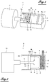
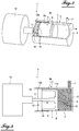
- FIG. 1 denotes a hydraulic unit according to the invention for supplying hydraulic power to a receiver (not shown) that can be part of a vehicle attitude correction device as will be seen later.
- the hydraulic unit 1 comprises a single-acting cylinder 2 comprising a cylindrical body 3, a piston 4 movable in translation in the body 3 of the cylinder 2, delimiting with an end wall 5 of the body 3 an internal chamber 6, which is filled hydraulic fluid under pressure (oil).
- the inner chamber 6 communicates with a radially outer tubular connector 7 connectable via a hydraulic line (not shown) to the receiver.
- the piston 4 comprises a high-pressure annular seal 8 in sliding contact with the internal face of the cylindrical body 3 of the jack 2 and has its skirt 9 directed into the body 3 in the opposite direction to the internal chamber 6.
- the annular seal sealing can be made of composite material.
- the hydraulic unit 1 also comprises an electric motor 10, preferably forming part of a geared motor assembly, and whose driving shaft 11 extends into the cylindrical body 3 of the jack 2 coaxially with the piston 4.
- the drive shaft 11 has its free end portion 11a T-shaped.
- the motor shaft 11 is connected to a mechanism 12,14 housed in the body 3 of the cylinder 2 opposite the skirt 9 of the piston 4, opposite the inner chamber 6 and which allows, according to the direction of rotation of the electric motor 10, to move in translation the piston 4 in the body 3 of the cylinder 2 in a direction of admission of the hydraulic fluid under pressure from the chamber 6 to and into the receiver through the connector 7 and the pipe hydraulic or in a direction of escape of the hydraulic fluid under pressure of the receiver in the chamber 6 through the hydraulic pipe and the connection 7.
- the mechanism for translational movement of the piston 4 in the body 3 of the jack 2 comprises a massive cylindrical ring 12 housed in the body 3 of the jack 2 perpendicular to the longitudinal axis of symmetry of the body 3 and whose central portion 13 in the form of through orifice is coupled to the motor shaft 11 of the electric motor 10 by a connection allowing a rotation of the ring 12 and its translation the along the drive shaft 11 in the body 3 of the jack 2 so as to allow the ring 12 to exert a thrust force in translation of the piston 4 in the body 3 of the jack 2 during the intake phase of the hydraulic fluid under pressure from the inner chamber 6 to and into the receiver.
- the ring 12 is threaded externally on its outer periphery and its entire width as referenced 12a and screwed into an internally threaded portion 3a of the body 3 of the cylinder 2.
- the threaded portion 3a of the body 3 extends over a portion of length of the body 3 allowing the ring 12 to occupy two end positions of end of admission of the hydraulic fluid represented in FIGS. Figures 1 and 2 and exhaust end of the hydraulic fluid shown in Figures 3 and 4 .
- the ring 12 At the extreme position of the end of admission of Figures 1 and 2 the ring 12 is in abutment against an internal annular shoulder 3b of the cylindrical body 3 of the jack 2 and at the end position of the exhaust end of the Figures 3 and 4 , the ring 12 is approximately in the vicinity of the free open end of the cylindrical body 3 of the jack 2 directed towards the electric motor 10.
- the mechanism for translational movement of the piston 4 comprises a circular ball raceway 14 interposed between the ring 12 and the annular end of the skirt 9 of the piston 4 to allow the translation of the latter without rotating it during the translational movement of the ring 12 with the piston 4 in the direction of admission of the hydraulic fluid under pressure in the receiver.
- connection between the central portion 13 of the ring 12 and the drive shaft 11 of the electric motor 10 may be of the spline type or, according to an alternative embodiment, of the prismatic type.
- the electric motor 10 and the jack 2, in use, are fixed relative to each other.
- the electric motor 10 When it is desired to supply hydraulic fluid under pressure to the receiver from the extreme end-of-exhaust position shown in FIGS. Figures 3 and 4 , the electric motor 10 is driven in a direction of rotation of the motor shaft 11 allowing the rotation and translation of the ring 12 in the body 3 of the cylinder 2 along the drive shaft 11 to the wall 5 of the body 3 of the cylinder 2, which ring 12 then exerts a thrust force on the piston 4 by the intermediate ball raceway 14 to move the piston 4 to the end wall 5 of the body 3 of the cylinder 2 and, therefore, provide fluid under hydraulic pressure to the receiver until the ring 12 comes in bearing on the circular shoulder 3b of the body 3 of the jack 2 as shown in FIGS. Figures 1 and 2 .
- the displacement of the piston 4 generates a certain flow rate of the hydraulic fluid at the operating pressure of the circuit supplying the receiver.
- the hydraulic unit 1 of the invention operates as a positive displacement pump with a flow rate limited by the cylinder capacity of the cylinder 2 at the operating pressure of the hydraulic circuit.
- the electric motor 10 is fed in the opposite direction to rotate the motor shaft 11 which rotates and moves the ring 12 in translation in the body 3 of the cylinder 2. along the motor shaft 11 in the opposite direction to the end wall 5 of the body 3.
- the pressure of the fluid exerted on the head 15 of the piston 4 displaces the latter to maintain it constantly bearing on the ring 12 by the intermediate ball raceway 14.
- the head 15 of the piston 4 again rests against the T-shaped end of the drive shaft 11 as shown in FIGS. Figures 3 and 4 .
- the pitch of the thread of the ring 12 is defined to retain the force exerted by the hydraulic fluid under pressure on the piston 4 to thereby make the displacement of the piston 4 irreversible.
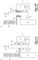
- the hydraulic unit 1 will now be described in its application to a trim correction device of a motor vehicle with reference to Figures 5A and 5B .
- FIGS 5A and 5B represent a part of a suspension associated with a wheel set of a motor vehicle, which suspension comprises for each wheel R a hydropneumatic suspension damper 20 whose body 21 has its lower end fixed to a support 22 of the wheel R and the rod 23 is integral with the body or chassis C of the vehicle and a metal suspension spring 24 interposed between the body C of the vehicle and a cup 25 forming part of the body 21 of the damper 20 and on which bears the end lower spring 24.
- the damper 20 is also equipped with a vehicle attitude correction device, to which belongs the hydraulic unit 1, and constituted in the present case by an annular jack 26 mounted concentrically on the body 21 of the damper 20, the annular cylinder 26 constituting the receiver to which is connected hydraulically the hydraulic unit 1 to perform the vehicle attitude correction.
- the annular jack 26 comprises a fixed portion 27 in the form of a circular wall, integral with the body 21 of the damper 20 and a movable cylindrical portion 28 surrounding the body 21 of the damper 20 and the fixed part 27 which defines in the movable cylindrical portion 28 two chambers of hydraulic fluid under pressure.
- the upper chamber of the annular cylinder 26 communicates with the chamber 6 of the hydraulic unit 1 via a hydraulic pipe 29 and the lower chamber of this jack communicates with a pipe, not shown, for recovering the hydraulic fluid.
- the cup 25 is integral with the movable cylindrical portion 28 of the annular jack 26 extending substantially perpendicularly to one side of the body 21 of the damper 20.
- the Figure 5A represents the situation in which the suspension spring 24 occupies its most relaxed position corresponding to a relatively low position of the cup 25 relative to the body 21 of the damper 20, that is to say that the movable cylindrical portion 28 of the annular jack 26 occupies its lowest position relative to its fixed portion 27.
- the piston 4 of the hydraulic unit 1 occupies its end position of exhaust end of Figures 3 and 4 corresponding to the low position of the movable cylindrical part 28.
- the electric motor 10 of the hydraulic unit 1 is controlled to move, by means of the drive shaft 11, the ring 12 and the ball raceway 14, the piston 4 in the body 3 of the cylinder 2 and supply in the upper chamber of the annular cylinder 26 hydraulic fluid under pressure to move vertically upwards the cup 25 as shown in FIG. Figure 5B .
- the electric motor 10 is controlled by a computer taking into account various parameters, such as the reference height of the vehicle body relative to the ground, to send hydraulic fluid under pressure in the annular jack 26 to maintain the the vehicle's attitude to its requested position.
- the design of the hydraulic unit 1 as described above is adapted to the type of application described above with reference to the Figures 5A and 5B , to the extent that a finite volume of hydraulic fluid is required at the pressure given by the load carried to maintain the attitude of the vehicle during quasi-static variations of the loading thereof.
- the hydraulic unit 1 is secured to the chassis of the vehicle.
- the hydraulic unit 1 can be connected by a pipe to the hydropneumatic suspension damper 20 designed to allow a trim of the vehicle, such a hydropneumatic damper being known per se for this purpose.
- a hydraulic unit 1 can be associated with each wheel of the vehicle, but it is also possible to envisage a hydraulic group per axle or vehicle wheel set to ensure a trim correction corresponding to a common pressure on this axle, the left distribution - right being controlled by an anti-roll bar of the vehicle.
- the above described hydraulic unit of the invention is of a much simpler structure than that of previously known hydraulic units and therefore much less expensive. It can easily adapt to any system of trim of a vehicle by its modularity while being easily integrated into the body to be controlled, which results in ease of assembly in the factory.
Landscapes
- Engineering & Computer Science (AREA)
- Mechanical Engineering (AREA)
- Physics & Mathematics (AREA)
- Fluid Mechanics (AREA)
- General Engineering & Computer Science (AREA)
- Vehicle Body Suspensions (AREA)
- Vehicle Cleaning, Maintenance, Repair, Refitting, And Outriggers (AREA)
- Arrangement Or Mounting Of Propulsion Units For Vehicles (AREA)
- Actuator (AREA)
Applications Claiming Priority (1)
| Application Number | Priority Date | Filing Date | Title |
|---|---|---|---|
| FR1652467A FR3049230B1 (fr) | 2016-03-23 | 2016-03-23 | Groupe hydraulique motorise destine a la correction d'assiette d'un vehicule automobile |
Publications (1)
| Publication Number | Publication Date |
|---|---|
| EP3222445A1 true EP3222445A1 (de) | 2017-09-27 |
Family
ID=56119553
Family Applications (1)
| Application Number | Title | Priority Date | Filing Date |
|---|---|---|---|
| EP17157302.5A Withdrawn EP3222445A1 (de) | 2016-03-23 | 2017-02-22 | Motorisierte hydraulikgruppe für die niveauregulierung eines kraftfahrzeugs |
Country Status (2)
| Country | Link |
|---|---|
| EP (1) | EP3222445A1 (de) |
| FR (1) | FR3049230B1 (de) |
Citations (5)
| Publication number | Priority date | Publication date | Assignee | Title |
|---|---|---|---|---|
| FR2689818A1 (fr) | 1992-04-08 | 1993-10-15 | Peugeot | Dispositif de correction d'assiette pour vehicule automobile. |
| US20090200761A1 (en) * | 2005-01-23 | 2009-08-13 | Stevens James C | Apparatus and method for shifting the center of gravity in a vehicle |
| US20110101632A1 (en) * | 2008-12-24 | 2011-05-05 | Kayaba Industry Co., Ltd. | Vehicle height adjusting device |
| EP2610090A2 (de) * | 2011-12-29 | 2013-07-03 | Robert Bosch Gmbh | Federbein eines Kraftfahrzeugs |
| US20140091552A1 (en) * | 2012-09-28 | 2014-04-03 | Kayaba Industry Co., Ltd. | Motorcycle |
-
2016
- 2016-03-23 FR FR1652467A patent/FR3049230B1/fr active Active
-
2017
- 2017-02-22 EP EP17157302.5A patent/EP3222445A1/de not_active Withdrawn
Patent Citations (5)
| Publication number | Priority date | Publication date | Assignee | Title |
|---|---|---|---|---|
| FR2689818A1 (fr) | 1992-04-08 | 1993-10-15 | Peugeot | Dispositif de correction d'assiette pour vehicule automobile. |
| US20090200761A1 (en) * | 2005-01-23 | 2009-08-13 | Stevens James C | Apparatus and method for shifting the center of gravity in a vehicle |
| US20110101632A1 (en) * | 2008-12-24 | 2011-05-05 | Kayaba Industry Co., Ltd. | Vehicle height adjusting device |
| EP2610090A2 (de) * | 2011-12-29 | 2013-07-03 | Robert Bosch Gmbh | Federbein eines Kraftfahrzeugs |
| US20140091552A1 (en) * | 2012-09-28 | 2014-04-03 | Kayaba Industry Co., Ltd. | Motorcycle |
Also Published As
| Publication number | Publication date |
|---|---|
| FR3049230A1 (fr) | 2017-09-29 |
| FR3049230B1 (fr) | 2019-04-26 |
Similar Documents
| Publication | Publication Date | Title |
|---|---|---|
| CA2923212C (fr) | Dispositif d'alimentation en fluide hydraulique d'un verin et mecanisme de commande de pas des pales d'une helice de turbomoteur comportant le verin | |
| FR2685902A1 (fr) | Amortisseur de train d'atterrissage d'aeronef. | |
| EP2698302B1 (de) | Hydraulische Lenkung von selbst fahrenden Fahrzeugen und Maschinen | |
| FR3050496A1 (fr) | Systeme de suspension hydraulique d'un vehicule | |
| FR3029977A1 (fr) | Dispositif de transmission d'un moteur, notamment pour un moteur a taux de compression et/ou a cylindree variable. | |
| FR2530571A1 (fr) | Dispositif de cylindre et piston, engrenage de direction assistee utilisant ce dispositif et procede de fabrication d'un piston pour ce dispositif | |
| FR2831934A1 (fr) | Boite de transmission basculante avec dispositif de rattrapage de jeu selon l'axe de basculement | |
| EP3222445A1 (de) | Motorisierte hydraulikgruppe für die niveauregulierung eines kraftfahrzeugs | |
| EP3060801A1 (de) | Hydraulische maschine mit einem durch einen konvexen, kreisförmigen teil gestützten kugellager | |
| FR2859770A1 (fr) | Actionneur a deux modes de fonctionnement | |
| FR2868381A1 (fr) | Soupape, notamment pour la production d'une pression controlee de fluide sous pression pour une direction assistee hydraulique | |
| FR2598983A1 (fr) | Systeme de regulation de la vitesse de croisiere pour vehicule automobile. | |
| EP0430746B1 (de) | Abstützvorrichtung, insbesondere für die Achse einer Hinterradaufhängung an der Karosserie eines Kraftfahrzeuges | |
| EP2570331B1 (de) | Lenkvorrichtung eines selbstfahrenden Fahrzeugs | |
| FR2473423A1 (fr) | Roue a diametre variable du type roue spherique et son application aux vehicules a transmission hydrostatique | |
| EP0379430A1 (de) | Lenkvorrichtung für mindestens einen Radsatz eines Fahrzeuges | |
| FR3103449A3 (fr) | Systeme de reglage d'un effort resistant s'opposant a un mouvement relatif de translation entre deux elements telescopiques | |
| FR2647062A1 (fr) | Train de roues a verin hydraulique et vehicule de transport lourd en faisant application | |
| EP0425329B1 (de) | Hydraulischer Zylinder mit veränderbarer Druckkraft und Lenkhilfe für ein mit solch einem Zylinder ausgestattetes Kraftfahrzeug | |
| EP4056448B1 (de) | Bedienungsvorrichtung in einem wagen eines schienenfahrzeugs | |
| FR2657563A1 (fr) | Essieu arriere de vehicule automobile comportant une traverse montee pivotante par rapport a la caisse et vehicule equipe d'un tel essieu. | |
| EP0418115A1 (de) | Steuerung einer Hinterradlenkung für ein Kraftfahrzeug mit vier lenkbaren Rädern | |
| FR2889150A1 (fr) | Dispositif de restitution d'effort au volant dans un systeme de direction decouplee d'un vehicule automobile | |
| EP0524094A1 (de) | Servoeinrichtung für Servolenkung eines Fahrzeuges | |
| WO2016139211A1 (fr) | Actionneur pour commande hydraulique d'embrayage |
Legal Events
| Date | Code | Title | Description |
|---|---|---|---|
| PUAI | Public reference made under article 153(3) epc to a published international application that has entered the european phase |
Free format text: ORIGINAL CODE: 0009012 |
|
| AK | Designated contracting states |
Kind code of ref document: A1 Designated state(s): AL AT BE BG CH CY CZ DE DK EE ES FI FR GB GR HR HU IE IS IT LI LT LU LV MC MK MT NL NO PL PT RO RS SE SI SK SM TR |
|
| AX | Request for extension of the european patent |
Extension state: BA ME |
|
| 17P | Request for examination filed |
Effective date: 20180312 |
|
| RBV | Designated contracting states (corrected) |
Designated state(s): AL AT BE BG CH CY CZ DE DK EE ES FI FR GB GR HR HU IE IS IT LI LT LU LV MC MK MT NL NO PL PT RO RS SE SI SK SM TR |
|
| GRAP | Despatch of communication of intention to grant a patent |
Free format text: ORIGINAL CODE: EPIDOSNIGR1 |
|
| INTG | Intention to grant announced |
Effective date: 20180608 |
|
| RIC1 | Information provided on ipc code assigned before grant |
Ipc: B66F 3/44 20060101ALI20180528BHEP Ipc: B60G 17/027 20060101AFI20180528BHEP |
|
| STAA | Information on the status of an ep patent application or granted ep patent |
Free format text: STATUS: THE APPLICATION IS DEEMED TO BE WITHDRAWN |
|
| 18D | Application deemed to be withdrawn |
Effective date: 20181019 |