EP3222785A2 - Dispositif de rinçage destiné à recevoir une solution de rinçage provenant d'une conduite et procédé de rinçage d'une conduite - Google Patents
Dispositif de rinçage destiné à recevoir une solution de rinçage provenant d'une conduite et procédé de rinçage d'une conduite Download PDFInfo
- Publication number
- EP3222785A2 EP3222785A2 EP17153802.8A EP17153802A EP3222785A2 EP 3222785 A2 EP3222785 A2 EP 3222785A2 EP 17153802 A EP17153802 A EP 17153802A EP 3222785 A2 EP3222785 A2 EP 3222785A2
- Authority
- EP
- European Patent Office
- Prior art keywords
- solution
- chlorine dioxide
- flushing
- rinsing
- flushing device
- Prior art date
- Legal status (The legal status is an assumption and is not a legal conclusion. Google has not performed a legal analysis and makes no representation as to the accuracy of the status listed.)
- Granted
Links
Images

Classifications
-
- E—FIXED CONSTRUCTIONS
- E03—WATER SUPPLY; SEWERAGE
- E03B—INSTALLATIONS OR METHODS FOR OBTAINING, COLLECTING, OR DISTRIBUTING WATER
- E03B7/00—Water main or service pipe systems
- E03B7/07—Arrangement of devices, e.g. filters, flow controls, measuring devices, siphons or valves, in the pipe systems
- E03B7/08—Arrangement of draining devices, e.g. manual shut-off valves
-
- E—FIXED CONSTRUCTIONS
- E04—BUILDING
- E04H—BUILDINGS OR LIKE STRUCTURES FOR PARTICULAR PURPOSES; SWIMMING OR SPLASH BATHS OR POOLS; MASTS; FENCING; TENTS OR CANOPIES, IN GENERAL
- E04H4/00—Swimming or splash baths or pools
- E04H4/12—Devices or arrangements for circulating water, i.e. devices for removal of polluted water, cleaning baths or for water treatment
- E04H4/1281—Devices for distributing chemical products in the water of swimming pools
-
- E—FIXED CONSTRUCTIONS
- E04—BUILDING
- E04H—BUILDINGS OR LIKE STRUCTURES FOR PARTICULAR PURPOSES; SWIMMING OR SPLASH BATHS OR POOLS; MASTS; FENCING; TENTS OR CANOPIES, IN GENERAL
- E04H4/00—Swimming or splash baths or pools
- E04H4/12—Devices or arrangements for circulating water, i.e. devices for removal of polluted water, cleaning baths or for water treatment
- E04H4/1209—Treatment of water for swimming pools
Definitions
- the invention relates to a flushing device for receiving a rinsing solution from a pipeline and a method for flushing a pipeline with the rinsing solution.
- the invention will be described in connection with the flushing of a drinking water system and may advantageously also be used with other pipelines carrying any fluid.
- a drinking water system which has a pipe and at least one tapping point for dispensing water or drinking water, with a chemical and / or biological solution (rinse solution) to flush (cleaning), in particular to counteract microbial contamination of the drinking water system.
- rinsing solution chemical and / or biological solution
- the object is achieved according to a first aspect of the invention by a flushing device for receiving a rinsing solution from a pipeline. Further, the object is achieved according to a second aspect of the invention by a method for purging a pipeline. Preferred developments form the respective subject matter of the dependent claims.
- the flushing device is configured to receive a flushing solution from at least one piping.
- the flushing device has a base element with an interior for receiving the rinse solution and a particular cup-shaped wall for limiting the interior space from the environment.
- the flushing device has at least one passage connection element which is permeable to the flushing solution and which is arranged in the wall and designed for connection to a supply line carrying the flushing solution, which can have a particularly funnel-shaped inlet opening for the flushing solution.
- the flushing device has a particular annular sealing element, which is mechanically connected to the wall and configured to limit a space between the base element and a drain, in which the rinse solution can be transferred from the interior to the environment, preferably seal.
- the flushing device With the flushing device according to the first aspect, it is possible to transfer the rinsing solution from the interior into the drain through the space between the base element and the drain which is limited by the sealing element from the environment, wherein the sealing element causes an uncontrolled escape of the rinsing solution from the interior the environment instead of in the drain can meet.
- the rinsing device can be used to counteract leakage of a gaseous part of the rinsing solution, in particular, to health problems of the user or third parties and / or the formation of stains by bleaching by the rinsing solution.
- the flushing device can advantageously be adapted to different outlets occurring in practice.
- the flushing device according to the invention can be operated with different rinsing solutions. Preferably, however, the use of the flushing device according to the invention is carried out with a chlorine dioxide solution.
- Aqueous chlorine dioxide solutions (ClO 2 ) are used because of the high oxidizing power of the chlorine dioxide, for example for disinfecting and deodorizing, especially in water treatment technology.
- the rinsing solution can be transferred from the interior through the limited space between the drain and the base element from the sealing element to the environment in the drain.
- the sealing element can encounter an uncontrolled escape of the rinsing solution from the interior into the environment instead of directly into the drain.
- the process can be used to counteract the escape of a gaseous part, potentially hazardous gases from the rinse solution, and / or the formation of stains by bleaching by the rinse solution. This is particularly advantageous when using a chlorine dioxide solution as a rinse solution.
- the method according to the invention for purging a pipeline is carried out by first supplying a flushing agent to the pipeline.
- the rinse may be any suitable rinse, depending on the particular application. The person skilled in the art will select the appropriate washing agent for the particular application in a suitable manner.
- the detergent is ideally fed as possible at the beginning of the pipe system to be cleaned. This can be done batchwise or continuously. For example, if the pipeline of a private household to be cleaned, the detergent is advantageously fed directly after the municipal water meter. Mixing the rinsing agent with the water passing through the pipe results in the rinsing solution. Due to this dilution, the concentration of the active ingredient in the rinse itself is naturally higher than in the rinse. By choosing the concentration of the active ingredient in the rinse, the amount or volume flow of rinse used, and the volume flow of water to which the rinse is added, the initial concentration of the active ingredient in the rinse may be adjusted. During the passage of the rinse solution through the tubing and the associated cleaning, disinfection, deodorization or removal of biofilms, legionella and other germs within the tubing, the active ingredient is gradually consumed and its concentration in the rinse solution decreases.
- the concentration of the active ingredient during the passage through the pipeline is no longer significantly reduced.
- the concentration of the active ingredient during the passage through the pipeline is no longer significantly reduced. According to the invention can thus be determined by comparison of the initial concentration of the active ingredient in the rinse solution (for example, directly after addition of the rinse and mixing with the guided through the pipe water over a defined mixing distance) with the concentration of the active ingredient after exiting the pipeline when the Cleaning, disinfection, deodorization or removal of biofilms, Legionella and other germs in the pipeline is completed and the rinsing can be stopped.
- the flushing device according to the invention is proposed. This is between the tap (for example, a faucet of a washbasin), where the rinse solution exits, and the drain (for example, the drain of a sink) arranged so that the rinse solution does not come into contact with the environment.
- the tap for example, a faucet of a washbasin
- the drain for example, the drain of a sink
- all taps of the pipe system to be cleaned are ideally provided with the flushing device according to the invention.
- the flushing device according to the invention preferably comprises more than one (for example, two) line connection elements.
- the base element is substantially rotationally symmetrical or cylindrical. This development can offer the advantage of lower manufacturing costs.
- the sealing element is designed to be elastically deformed between the base element or its wall and the surface having the drainage.
- the sealing element may be formed with a polymer foam or with an elastomer.
- the particular annular sealing element is dimensioned to completely surround the drain.
- the inner diameter of the sealing element may be larger than the diameter of the drain.
- the wall of the base element has a drain opening for the flushing solution.
- the drain opening may be disposed on the wall such that the drain opening is adjacent and facing the drain when flushing the tubing (use condition).
- the wall preferably forms a flat, particularly preferably annular, section around the discharge opening.
- the base element has one, two, three or more closable removal openings which are respectively arranged in the wall and through which a sample of the flushing solution can be taken from the interior.
- the at least one closable removal opening can advantageously point upwards in the use state, so that the solution located in the interior can not unintentionally escape from the interior when the removal opening is opened.
- the removal opening can be advantageously closed by a stopper.
- the base element has a first connecting element for supporting the sealing element, in particular in the use state of the flushing device, wherein the first connecting element extends adjacent to the drainage opening.
- the first connection element may extend with a closed contour, in particular a circular ring, around the discharge opening and out of the wall into the environment.
- the first connecting element extends as a web or rib from the wall.
- the first connection element may have at least two or three projections each extending out of the wall into the environment, against which the sealing element may abut.
- the connecting element counteract an unintentional displacement of the sealing element relative to the base element, in particular its state of use.
- the diameter of a ring-shaped extending first connecting element may be between 50 and 70 mm, preferably about 60 mm.
- the flushing device has a supplementary element which has a base surface and is mechanically connectable to the base element such that the base surface and a base surface of the base element are arranged in a common plane when the supplementary element is mechanically connected to the base element.
- the Supplementary element may have a locking means for mechanical connection with the base element.
- a flat contact surface of the supplementary element, which is arranged essentially perpendicular to the base surface, serves for touching or for contacting the base element, in particular in the state of use, in particular when the supplementary element is mechanically connected to the base element.
- the supplementary element may be formed as a hollow body, whereby material can be saved.
- the flushing device has a second connecting element, which is designed to support the sealing element and extends along the base surface and the base surface.
- the second connection element can have all the properties and configurations of the first connection element.
- the second connecting element differs in that a first portion of the second connecting element extends along the base surface and a second portion of the second connecting element along the base surface.
- the first portion and the second portion of the second connecting element together form an annular ridge or rib.
- the second connecting element can advantageously be configured for supporting a sealing element whose diameter is greater than that of a sealing element which can be supported by the first connecting element, in particular for larger outflows.
- the diameter of an annularly extending second connecting element may be between 110 and 130 mm, preferably about 120 mm.
- the flushing device has at least one permeable core element for the flushing solution, which can be inserted into the supply line.
- the core element may be formed as a pipe section or as a truncated cone with a fluid-permeable in particular for the rinse solution channel, so that a fluid can pass through the core element into the interior.
- the core element can be used to support the Serving lead, in particular when the supply line is formed with a hose, and / or to counteract an undesirable deformation of the supply line.
- the core element may have at least one circumferential bead, in particular for connection to the line connection element.
- the line connection element has at least one, two, three or more pipe sockets, which each extend from the wall of the base element into the environment and which can each receive a first end of the supply line.
- the at least one pipe stub is configured with a channel that is in particular fluid-permeable for the rinsing solution, so that a fluid or the rinsing solution can reach the interior through the pipe stub.
- the pipe socket and the core element can be configured in common for clamping the pipe or as pinch system for the pipeline.
- the pipe socket can have at least one peripheral recess for connection to the core element, in particular with its bead, in particular for engagement of the bead.
- the flushing device has a dividing wall, which can be fluid-tightly connected to the wall and configured to subdivide the interior into at least a first partial space and a second partial space.
- the partition wall is arranged in the interior.
- the dividing wall may be formed as a body extending substantially perpendicular to the base surface, in particular in the direction of the at least one line connection element, in particular as a web or rib.
- the partition may have three or more interconnected partition sections which may divide the interior into three or more subspaces.
- the rinsing solution can be stowed in front of an obstacle or web which extends from the wall into the interior.
- This can be the Partial chambers advantageous samples of the rinse solution can be taken separately from different supply lines and examined.
- the flushing device has at least one fluid guide element, which is designed to redirect the flushing solution entering the interior through the line connection element and is arranged in the interior.
- the fluid guide element serves in particular for deflecting the entering rinse solution in the direction of the wall of the base element.
- the fluid guide element may be connected to the wall and / or partition wall mechanically, preferably cohesively.
- the fluid guide element can have a baffle surface for the fluid entering the interior, which can preferably form an angle between 80 ° and 20 ° with a cross-sectional area or inlet opening of the line connection element or with a longitudinal axis of the pipe socket, particularly preferably about 45 °.
- the baffle surface can be inclined up to about 50 ° with respect to the horizontal.
- the baffle is arranged in the use state approximately horizontally.
- the flushing device preferably has a separate fluid-conducting element for each incoming flushing solution flow or for each line connection element.
- the at least one fluid guiding element can shield the discharge opening in such a way that the entering rinsing solution flow is deflected by means of the fluid guiding element in the direction of the wall of the basic element.
- the fluid guiding element can promote a minimum fill level of the rinsing solution in the interior or subspace, whereby the removal of a sample can be simplified.
- the base element has an independent or separate cover element which can be mechanically connected to the base element for closing the interior or the wall, in particular a pot-shaped wall, in particular by latching means.
- the at least one line connection element is arranged on the cover element and the at least one removal opening can be arranged on the cover element.
- the pipe socket (s) may extend from the cover element into the environment.
- the flushing device has the supply line, which is configured to guide the flushing solution, which is fluid-conductively connectable to the pipeline and the line connection element, which is designed to counteract an escape of the flushing solution out of the pipeline into the environment, which may be tubular can.
- the supply line may be formed as a section of a film tube, whereby the flushing device can be advantageously adapted to the local conditions, which advantageously the distance between the base element and the tap can be compensated.
- the flushing device has a plurality of these supply lines, which are each fluid-conductively connectable to different line connection elements or tapping points. This development can be advantageously adapted to various pipes or taps occurring in practice.
- the flushing device has at least one support device, which is designed to support the base element with respect to a surface having the outflow.
- the support means in particular a first leg of the support means, is mechanically connectable to the wall, preferably latching or form-fitting.
- the support device in particular a second leg formed in one piece with the first leg, may have an adhesive element which is configured for detachably connecting the support device to the surface having the outflow, which is formed in particular with at least one suction cup.
- the support means in particular a second leg, can be loaded with a weight which serves for detachably connecting the support means to the surface having the outflow, in particular if the surface having the outflow is rougher.
- the self-weight of the support means itself may serve to releasably connect the support means to the drainage-bearing surface, particularly if the drainage-bearing surface is rougher.
- the support means is threaded to adjust the distance between the base member and the drainage surface and / or to conform to the geometry of the drain having surface, which may be curved.
- the support means extends from a portion of the wall, which lies in the use state opposite the drain.
- the flushing device may have a plurality, in particular two or three, of these support devices, which may preferably be arranged uniformly spaced along the wall.
- the at least one supporting device can be used to counteract the escape of a gaseous part of the rinsing solution in particular and the formation of stains by bleaching by the rinsing solution.
- the support means can be combined with the supplementary element.
- the flushing device has at least one adhesive element, in particular at least one suction cup, which is connectable in particular to the base surface of the base element.
- This adhesive element serves to connect the flushing device to the drainage surface.
- the rinsing device may have two or three of these adhesive elements for improved connection of the rinsing device to the drainage surface.
- the rinsing device can have two adhesive elements lying opposite each other with respect to a longitudinal axis of the base element or with respect to the discharge opening.
- step S5 can be advantageously counteracted leakage of a particular gaseous portion of the rinse solution into the environment and the formation of stains by bleaching by the rinse solution.
- the step S11 may offer the advantage that unintentional displacement of the sealing element with respect to the base body has occurred. This can be used to counteract the escape of a particular gaseous part of the rinse solution and / or the formation of stains by bleaching by the rinse solution.
- step S12 can advantageously be used to check the chemical composition and / or the microbial contamination of the rinsing solution after it leaves the pipeline. If step S12 takes place during or after step S16, then it can advantageously be determined whether there are still residues of the rinsing solution in the pipeline.
- step S13 an undesired deformation of the supply line can be counteracted and / or the clamping of the supply line can be prepared.
- the step S14 serves, in particular together with step S13, to simplify the connection of the supply line to the line connection element.
- the feed line can be cut from a film tube such that the length of the feed line is adapted to the distance between the tap point and the power connection element.
- a first end of the feed line may be inserted into the pipe socket, in particular after step S13.
- a second end of the supply line can be slipped over the tapping point and fastened in particular with a cable tie.
- step S15 offers the advantage that the flushing device can be prepared for a drain with a larger diameter.
- a larger sealing element can be supported by the base surface and the base surface.
- step S16 is performed instead of step S3, then residues of the rinse solution or residues of a constituent of the rinse solution can advantageously be removed from the pipeline.
- step S16 may take place instead of step S3. The removal of residues of the rinse solution from the pipeline with step S16 can be checked by the particular repeated implementation of step S12.
- step S3 In order to be able to diffuse an active substance of the rinsing agent or the rinsing solution as far as possible into dead lines which are not constantly perfused, the concentration of active substance at the entrance of a dead line must remain as high as possible. For this purpose, always new rinse solution must be replenished.
- step S17 Preferably, step S17 lasts several minutes, followed by step S3, in particular below At sight.
- an inadvertent irretrievable flushing solution outlet can be counteracted.
- the rinsing solution in the pipeline can act on the pipeline to improve the result of the cleaning.
- advantageous parts of the rinse solution can diffuse into dead arms of the pipeline and contribute to their cleaning.
- the time interval At, during which step S3 is interrupted can be between 10 s and 600 s, preferably between 60 s and 180 s. This allows the rinse solution to better affect the pipeline.
- the method for flushing a pipeline with the flushing device according to the invention can be carried out with any suitable flushing solution or with any suitable flushing agent, depending on the specific application.
- the person skilled in the art will select a suitable rinsing solution or a suitable rinsing agent for the respective application in a suitable manner.
- the rinsing solution or the rinsing agent may comprise an oxidizing agent or disinfectant, surface-active, alkaline or acidic as well as complexing cleaning agents.
- the rinsing solution or the rinsing agent may contain as active ingredient advantageously one or more substances selected from the group, for example chlorine dioxide, hydrogen peroxide, ozone, potassium permanganate, hypochlorite or chlorine and nonionic, cationic or anionic surfactants, bases such as sodium hydroxide or acids such as citric acid, complexing agents such as amidosulfonic acid, EDTA, NTA, etc ...
- the rinse solution or the rinsing agent contains chlorine dioxide (ClO 2).
- Aqueous solutions of chlorine dioxide are used for bleaching, disinfecting and deodorizing, especially in water treatment technology, due to the high oxidizing power of chlorine dioxide.
- chlorine dioxide solutions for the above-mentioned applications have not usually been sold as ready-made solutions, but have been freshly prepared and applied on-site, ie on-site.
- the flushing agent used is a chlorine dioxide solution which contains chlorine dioxide in an amount of about 0.1 to about 4.5% by weight, preferably in the range of about 0.3 to about 2% by weight preferably in the range of about 0.3 to about 0.6 wt% or in the range of about 0.6 to about 1 wt%.
- This chlorine dioxide solution may be prepared, for example, by a process which comprises (a) providing chlorite, (b) providing peroxodisulfate, and (c) combining chlorite and peroxodisulfate in an aqueous system and in a molar ratio of peroxodisulfate to Chlorite [S 2 O 8 2- ] / [ClO 2 - ] greater than 1 to form the aqueous chlorine dioxide solution, with no additional buffer being added to produce the aqueous chlorine dioxide solution.
- This chlorine dioxide solution as a rinse to the piping, the rinse solution is obtained.
- the present invention further relates to the use of the flushing device according to the invention with a rinse solution containing chlorine dioxide.
- a rinse solution containing chlorine dioxide can be used as a rinse.
- the chlorine dioxide-containing rinse is a chlorine dioxide solution containing chlorine dioxide in an amount of about 0.1 to about 4.5 weight percent, preferably in the range of about 0.3 to about 2 weight percent, more preferably in the range from about 0.3 to about 0.6 wt% or in the range of about 0.6 to about 1 wt%.
- the chlorine dioxide-containing rinse solution (ie the rinse together with the water from the pipeline) is a chlorine dioxide solution containing chlorine dioxide in an amount of about 1 to about 2000 mg / l, preferably from about 6 to about 100 mg / more preferably in the range of about 10 to about 70 mg / l.
- a development is a use for disinfection, in particular for disinfection of drinking and bathing water, for the oxidation, deodorizing, for the treatment of industrial and waste water and / or for the removal of biofilms, Legionella or other germs in drinking water systems, air conditioning, recooling, water treatment plants, boilers or pools preferred.
- the rinse agent may be added from a portable container or drum into the tubing. This can advantageously be facilitated the provision of the detergent at the point of cleaning.
- the rinsing agent may be given an opportunity to act on the pipeline during a time interval of about 120 seconds to 720 seconds, and in particular for diffusion of an active ingredient of the rinsing agent into a dead line.
- the cleaning of the pipeline, in particular the dead line be improved.
- the chlorine dioxide concentration K1 in the rinsing solution directly after addition of the rinsing agent represents the initial chlorine dioxide concentration before the rinsing process. This can be determined from the amount or the volume flow and the concentration of the chlorine dioxide rinse added and the volume flow of the water in the pipeline to be cleaned be calculated. Alternatively, the chlorine dioxide concentration can also be determined experimentally.
- a sample of the rinse solution is taken at the beginning of the pipeline and examined by suitable measurement methods. Preferably, the sampling takes place after a defined mixing distance (for example 1 m) according to the location of the addition of the rinsing agent.
- the chlorine dioxide concentration of the rinse solution K1 is preferably 1 to 2000 mg / L, more preferably 6 to 100 mg / L, even more preferably 10 to 70 mg / L.
- a mixing line in which the chlorine dioxide-containing detergent is added.
- Step S29 may include rinsing with a reduced flow rate of the rinse solution compared to step S26.
- the duration of rinsing can be proportional to one of the chlorine dioxide concentrations K1, K2.
- the rinsing can be done for several hours. This development of step S29 can be achieved by diffusing chlorine dioxide into regions of the pipeline, which can not be flowed through directly by the rinsing solution, for example dead lines, an improved cleaning of the pipeline.
- FIG. 1 shows schematically and in perspective a further development of the flushing device 1.
- the base member 2 has a cup-shaped wall 4 and a cover member 21 which is in particular positively connected to the wall, in particular with at least one locking means.
- This formation of the base allows manufacturing by an injection molding process or a three-dimensional printing process.
- the basic element can thread, holes and / or locking elements for the supplementary element, for supporting devices, for a Threaded rod to be produced for adhesive elements, etc., which may allow a more cost-effective completion of the flushing device.
- the first connecting element 9 extend as an annular web and a portion of the second connecting element 13 likewise embodied as a web.
- the base surface faces an outflow and the cover element is arranged at the upper end of the base element.
- the first connection element surrounds the discharge opening 7 in the base area of the base element.
- Two or more support means 22, 22a can be connected to the wall with locking means.
- the support means may comprise suction cups. Threaded rods can be guided by internal threads of the support means.
- the support means may be made by an injection molding process or by a three-dimensional printing process. In prototyping of the support element, threads, holes and / or latching elements for a threaded rod, for adhesive elements, etc., can be generated, which may allow a more cost-effective completion of the flushing device.
- the supplementary element 10 is mechanically connectable to the base element, in particular with latching means, and has a portion of the second connecting element 13. If the supplementary element is mechanically connected to the base element, then the base of the base element and the base surface of the supplementary element extend in the same plane and the second connecting element 13 forms an annular web with a larger inner diameter than that of the first connecting element.
- Two pipe connection elements 15 designed as line connection elements extend from the cover element.
- the cover element also has two removal openings 8, 8a.
- Two core elements 14, 14 a have beads, which can engage 15 for clamping a supply line in not shown recesses of the pipe socket.
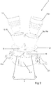
- FIG. 2 schematically shows another view of the flushing of the FIG. 1 , The following is especially in the FIG. 1 invisible components of the flushing received.
- interior 3 of the basic element is the partition wall arranged, which divides the interior into two subspaces and fluid-tight, in particular cohesively connected to the wall.
- the flushing device has two fluid guide elements 18, which are arranged in the interior adjacent to the pipe socket.
- the fluid guide elements can be mechanically, in particular materially connected, connected to the wall of the base element and / or the partition wall.
- the fluid guide elements each have a baffle surface and this baffle surface forms an angle between 80 ° and 20 ° with a cross-sectional area, the inlet opening or the longitudinal axis of the adjacent pipe socket.
- the baffle surface can be inclined up to about 50 ° with respect to the horizontal.
- the baffle is arranged in the use state approximately horizontally.
- An obstacle or web can extend around the discharge opening in the interior, which serves for damming up the rinsing solution and / or for removing a sample of the rinsing solution.
- a portion of the flowing rinsing solution can be continuously accumulated in the rinsing device, which can then be sucked out for sampling, for example by syringe.
- the flushing device can be placed close to a drain, so that the flushing solution emerging through a hole in the bottom of the base element can flow directly into the drain without contact with the environment.
- a sink is pressed from the bottom of the base member designed as a flexible foam-like plastic ring sealing element on the sink.
- the plastic ring must be soft enough to adapt to the individual shape of the respective sink.
- the contact pressure can be built up by the fact that the flushing device sucks on the surface of the washbasin by means of suction cups.
- the basic element or the support device, in particular the second leg, can be loaded with a weight, which serves for detachably connecting the support device to the surface having the outflow.
- the self-weight of the support means itself may serve to releasably connect the support means to the drainage-bearing surface, particularly if the drainage-bearing surface is rougher.
- a feed line designed as a flexible film tube is applied between tapping point and the pipe socket.
- the film tube is pulled over the tapping point (for example, completely over a shower head) and fixed by means of cable ties.
- the other end of the film tube is squeezed with the core element in the pipe socket.
- the basic element may have three storage chambers or partial spaces and the cover element may have three inlet funnels or pipe sockets.
- the complete collection of the sampling points is important. At all outlets, an outlet system is required to encapsulate the water withdrawal. In this case also take-off points are to be taken into account, which may have already been dismantled or are no longer subject to regular use.
- the encapsulation is carried out with a flexible hose system, here with a PE film hose, which is clamped in our specially made connection system.
- the dosing station is installed directly behind the water meter.
- the station is equipped with a system separator, dosing lance and mixing section in accordance with the requirements of the drinking water purifier when dealing with drinking water.
- the heater Before starting the flushing, the heater is turned off for hot water preparation.
- the method can also be used at higher temperatures.
- the incoming fresh water is supplied to the city water meter in the dosing station with chlorine dioxide.
- the farthest extraction points are opened in the first step and allowed to run water until chlorine dioxide is to be measured.
- the chlorine dioxide is added to the water flow proportionally proportional, the mixture is homogenized in a mixing line and then fed to the sampling points.
- Blending is e.g. a commercial 0.6% chlorine dioxide solution with the trade name Clorious2 from a 200 liter storage drum or 30 liter container.
- the fixed concentration is determined photometrically. It is a measure of the concentration that should be recovered after passing through the pipeline network at the sampling points. Subsequently, photometric measurements are taken at all tapping points (cold and hot water) at regular intervals, until the disinfectant solution without food can be found everywhere at all sampling points. The taps are closed again after the yellow disinfectant solution has been tapped, then opened every few minutes. Occurs then the disinfectant solution then, in part only after repeated repetition, without consumption from a tap, it can be concluded that the system has no more food, so the ingredients of the water like microorganisms and biofilm have reacted in the line with the chlorine dioxide and thus oxidized (removed at best).
- the above-described flushing method in all drinking water systems applicable, for example, on ships, boats, in vehicles, trains, aircraft, but also drinking water tanks or power lines, sewer systems, service networks, cooling systems, etc ..
- the disposal of the rinse water can easily via the sewer into the Drains take place. Even at high residual concentrations of chlorine dioxide, the water poses no danger to the sewage system. Residual amounts of oxidizing agent are quickly consumed there. Wastewater treatment plants are not affected. After consumption, chloride and sulfate are formed in very small amounts.
Landscapes
- Engineering & Computer Science (AREA)
- Water Supply & Treatment (AREA)
- Architecture (AREA)
- Civil Engineering (AREA)
- Structural Engineering (AREA)
- Health & Medical Sciences (AREA)
- Life Sciences & Earth Sciences (AREA)
- Hydrology & Water Resources (AREA)
- Public Health (AREA)
- Cleaning By Liquid Or Steam (AREA)
- Cleaning In General (AREA)
Applications Claiming Priority (1)
| Application Number | Priority Date | Filing Date | Title |
|---|---|---|---|
| DE102016103675.7A DE102016103675A1 (de) | 2016-03-01 | 2016-03-01 | Spülvorrichtung zum Aufnehmen einer Spüllösung aus einer Rohrleitung sowie Verfahren zum Spülen der Rohrleitung |
Publications (3)
| Publication Number | Publication Date |
|---|---|
| EP3222785A2 true EP3222785A2 (fr) | 2017-09-27 |
| EP3222785A3 EP3222785A3 (fr) | 2017-12-20 |
| EP3222785B1 EP3222785B1 (fr) | 2020-04-29 |
Family
ID=57944322
Family Applications (1)
| Application Number | Title | Priority Date | Filing Date |
|---|---|---|---|
| EP17153802.8A Active EP3222785B1 (fr) | 2016-03-01 | 2017-01-30 | Dispositif de rinçage destiné à recevoir une solution de rinçage provenant d'une conduite et procédé de rinçage d'une conduite |
Country Status (3)
| Country | Link |
|---|---|
| EP (1) | EP3222785B1 (fr) |
| DE (1) | DE102016103675A1 (fr) |
| ES (1) | ES2798824T3 (fr) |
Families Citing this family (3)
| Publication number | Priority date | Publication date | Assignee | Title |
|---|---|---|---|---|
| DE102017217019A1 (de) * | 2017-09-26 | 2019-03-28 | Siemens Aktiengesellschaft | Verfahren zum Austragen von Füllmaterial aus einem hohlen Bauteil, Reinigungsvorrichtung zum Austragen von Füllmaterial, Verfahren zu deren Herstellung und Programm zur Durchführung dieses Verfahrens |
| PL3527727T3 (pl) * | 2018-02-14 | 2022-08-01 | A.P.F. Aqua System Ag | Urządzenie do przeprowadzania fluidu do przeprowadzania roztworu płuczącego z przewodu rurowego |
| FR3140001A1 (fr) * | 2022-09-23 | 2024-03-29 | Suez International | procédé de nettoyage d’une canalisation polluée |
Citations (1)
| Publication number | Priority date | Publication date | Assignee | Title |
|---|---|---|---|---|
| WO2012084247A1 (fr) | 2010-12-23 | 2012-06-28 | A.P.F. Aqua System Ag | Procédé de fabrication d'une solution aqueuse, stable, de dioxyde de chlore |
Family Cites Families (8)
| Publication number | Priority date | Publication date | Assignee | Title |
|---|---|---|---|---|
| US3688907A (en) * | 1970-12-11 | 1972-09-05 | August J Oravec | Automatically self-cleaning self-aerating tropical fishaquarium |
| US4718129A (en) * | 1987-05-01 | 1988-01-12 | Miller Robert E | Improved swimming pool vacuum apparatus |
| US4740307A (en) * | 1987-10-13 | 1988-04-26 | Buelteman Vernon P | Swimming pool water skimming and vacuuming apparatus |
| EP0487214A1 (fr) * | 1990-11-19 | 1992-05-27 | The Commonwealth Industrial Gases Limited | Appareil de nettoyage pour distributeur de boisson |
| FR2714099A1 (fr) * | 1993-12-21 | 1995-06-23 | Julien Bernard | Dispositif d'aspiration et de filtrage de tous types de déchets gros et importants en volume pour bassins et piscines. |
| US6374848B1 (en) * | 1999-04-15 | 2002-04-23 | Mcghee John D. | Automatic mechanism for cut-off and drainage of under low-freezing ambient temperature conditions |
| US6391122B1 (en) * | 1999-11-23 | 2002-05-21 | Diversey Lever, Inc. | Segmented process for cleaning-in-place |
| EP1964983B1 (fr) * | 2007-03-01 | 2010-10-13 | Geberit International AG | Dispositif destiné au lavage automatique de conduites d'eau |
-
2016
- 2016-03-01 DE DE102016103675.7A patent/DE102016103675A1/de not_active Withdrawn
-
2017
- 2017-01-30 ES ES17153802T patent/ES2798824T3/es active Active
- 2017-01-30 EP EP17153802.8A patent/EP3222785B1/fr active Active
Patent Citations (1)
| Publication number | Priority date | Publication date | Assignee | Title |
|---|---|---|---|---|
| WO2012084247A1 (fr) | 2010-12-23 | 2012-06-28 | A.P.F. Aqua System Ag | Procédé de fabrication d'une solution aqueuse, stable, de dioxyde de chlore |
Also Published As
| Publication number | Publication date |
|---|---|
| ES2798824T3 (es) | 2020-12-14 |
| EP3222785A3 (fr) | 2017-12-20 |
| DE102016103675A1 (de) | 2017-09-07 |
| EP3222785B1 (fr) | 2020-04-29 |
| HK1244040A1 (zh) | 2018-07-27 |
Similar Documents
| Publication | Publication Date | Title |
|---|---|---|
| EP2585643B1 (fr) | Système de stérilisation de douche et son procédé d'utilisation | |
| DE60301067T2 (de) | Automatisches endoskopnachbehandlungsgerät | |
| CH709194A2 (de) | Wärmetauscher für eine Dusche oder Badewanne. | |
| EP3222785B1 (fr) | Dispositif de rinçage destiné à recevoir une solution de rinçage provenant d'une conduite et procédé de rinçage d'une conduite | |
| DE102018112362A1 (de) | Vorrichtung und Verfahren zur Reinigung einer Trinkwasseraufbereitungsanlage | |
| EP2078174B1 (fr) | Système de traitement de l'eau | |
| JPH09182684A (ja) | 薬剤徐放装置を備える水槽 | |
| HK1244040B (en) | Flushing device for holding a flushing liquid from a conduit and method for flushing the pipeline | |
| DE19528160C2 (de) | Rohr- und Schlauchinstallation an und in Mediensäulen für die Behandlung von Körperflüssigkeiten, insbesondere für ein Dialysegerät | |
| EP0027980A1 (fr) | Procédé et installation pour rincer, nettoyer, désinfecter et pour le revêtement intérieur d'une conduite, en particulier une conduite d'eau dans une nouvelle construction | |
| DE102007016819A1 (de) | Toilettensystem mit integrierter Vorrichtung zur Abgabe von Sanitärzusätzen | |
| DE102011076222A1 (de) | Verfahren zur Überwachung einer Reinigung und/oder Desinfektion mindestens eines Teils einer Prozessanlage | |
| EP3527727B1 (fr) | Dispositif de transfert de fluide destiné à transférer une solution de rinçage d'une conduite | |
| US20110278236A1 (en) | Water treatment device | |
| KR20010045414A (ko) | 정, 배수지의 소독방법 | |
| DE102010025818A1 (de) | Dosiervorrichtung zur Abgabe von Duft-Desinfektions- oder Reinigungsmittel in Speicherbehälter | |
| EP1901860B1 (fr) | Dispositif et procede de nettoyage et / ou de desinfection de filtres | |
| DE102005031232B4 (de) | Vorrichtung und Verfahren zur Reinigung und/oder Desinfektion von Filtern | |
| DE202015105537U1 (de) | Reinigungsvorrichtung zur Desinfektion und Spülung von Trinkwasserarmaturen | |
| EP2954960A2 (fr) | Unité de désinfection et/ou de nettoyage de tuyaux, en particulier de conduites d'eau potable et procédé de désinfection et/ou de nettoyage de telles conduites | |
| WO2007057940A1 (fr) | Appareil et procédé de désinfection d’eau | |
| AT515901B1 (de) | Wasserinstallation | |
| DE202025101371U1 (de) | Einrichtung zur Zuleitung von Grauwasser von einem Grauwassererzeuger zu einem Grauwasserabnehmer und System zur Grauwasserverwendung | |
| DE10244323B4 (de) | Vorrichtung für die Behandlung von fetthaltigem Abwasser vor dessen Einleitung in das Abwasserleitungsnetz | |
| DE2636223C3 (de) | Geruchverschluß |
Legal Events
| Date | Code | Title | Description |
|---|---|---|---|
| PUAI | Public reference made under article 153(3) epc to a published international application that has entered the european phase |
Free format text: ORIGINAL CODE: 0009012 |
|
| STAA | Information on the status of an ep patent application or granted ep patent |
Free format text: STATUS: THE APPLICATION HAS BEEN PUBLISHED |
|
| AK | Designated contracting states |
Kind code of ref document: A2 Designated state(s): AL AT BE BG CH CY CZ DE DK EE ES FI FR GB GR HR HU IE IS IT LI LT LU LV MC MK MT NL NO PL PT RO RS SE SI SK SM TR |
|
| AX | Request for extension of the european patent |
Extension state: BA ME |
|
| PUAL | Search report despatched |
Free format text: ORIGINAL CODE: 0009013 |
|
| AK | Designated contracting states |
Kind code of ref document: A3 Designated state(s): AL AT BE BG CH CY CZ DE DK EE ES FI FR GB GR HR HU IE IS IT LI LT LU LV MC MK MT NL NO PL PT RO RS SE SI SK SM TR |
|
| AX | Request for extension of the european patent |
Extension state: BA ME |
|
| RIC1 | Information provided on ipc code assigned before grant |
Ipc: E04H 4/16 20060101ALI20171116BHEP Ipc: E03B 7/08 20060101AFI20171116BHEP |
|
| STAA | Information on the status of an ep patent application or granted ep patent |
Free format text: STATUS: REQUEST FOR EXAMINATION WAS MADE |
|
| 17P | Request for examination filed |
Effective date: 20180615 |
|
| RBV | Designated contracting states (corrected) |
Designated state(s): AL AT BE BG CH CY CZ DE DK EE ES FI FR GB GR HR HU IE IS IT LI LT LU LV MC MK MT NL NO PL PT RO RS SE SI SK SM TR |
|
| REG | Reference to a national code |
Ref country code: HK Ref legal event code: DE Ref document number: 1244040 Country of ref document: HK |
|
| GRAP | Despatch of communication of intention to grant a patent |
Free format text: ORIGINAL CODE: EPIDOSNIGR1 |
|
| STAA | Information on the status of an ep patent application or granted ep patent |
Free format text: STATUS: GRANT OF PATENT IS INTENDED |
|
| INTG | Intention to grant announced |
Effective date: 20191203 |
|
| GRAS | Grant fee paid |
Free format text: ORIGINAL CODE: EPIDOSNIGR3 |
|
| GRAA | (expected) grant |
Free format text: ORIGINAL CODE: 0009210 |
|
| STAA | Information on the status of an ep patent application or granted ep patent |
Free format text: STATUS: THE PATENT HAS BEEN GRANTED |
|
| AK | Designated contracting states |
Kind code of ref document: B1 Designated state(s): AL AT BE BG CH CY CZ DE DK EE ES FI FR GB GR HR HU IE IS IT LI LT LU LV MC MK MT NL NO PL PT RO RS SE SI SK SM TR |
|
| REG | Reference to a national code |
Ref country code: GB Ref legal event code: FG4D Free format text: NOT ENGLISH |
|
| REG | Reference to a national code |
Ref country code: CH Ref legal event code: EP |
|
| REG | Reference to a national code |
Ref country code: AT Ref legal event code: REF Ref document number: 1263480 Country of ref document: AT Kind code of ref document: T Effective date: 20200515 |
|
| REG | Reference to a national code |
Ref country code: DE Ref legal event code: R096 Ref document number: 502017004921 Country of ref document: DE |
|
| REG | Reference to a national code |
Ref country code: IE Ref legal event code: FG4D Free format text: LANGUAGE OF EP DOCUMENT: GERMAN |
|
| REG | Reference to a national code |
Ref country code: CH Ref legal event code: NV Representative=s name: PATENTANWAELTE SCHAAD, BALASS, MENZL AND PARTN, CH |
|
| REG | Reference to a national code |
Ref country code: NL Ref legal event code: FP |
|
| REG | Reference to a national code |
Ref country code: LT Ref legal event code: MG4D |
|
| PG25 | Lapsed in a contracting state [announced via postgrant information from national office to epo] |
Ref country code: NO Free format text: LAPSE BECAUSE OF FAILURE TO SUBMIT A TRANSLATION OF THE DESCRIPTION OR TO PAY THE FEE WITHIN THE PRESCRIBED TIME-LIMIT Effective date: 20200729 Ref country code: LT Free format text: LAPSE BECAUSE OF FAILURE TO SUBMIT A TRANSLATION OF THE DESCRIPTION OR TO PAY THE FEE WITHIN THE PRESCRIBED TIME-LIMIT Effective date: 20200429 Ref country code: SE Free format text: LAPSE BECAUSE OF FAILURE TO SUBMIT A TRANSLATION OF THE DESCRIPTION OR TO PAY THE FEE WITHIN THE PRESCRIBED TIME-LIMIT Effective date: 20200429 Ref country code: GR Free format text: LAPSE BECAUSE OF FAILURE TO SUBMIT A TRANSLATION OF THE DESCRIPTION OR TO PAY THE FEE WITHIN THE PRESCRIBED TIME-LIMIT Effective date: 20200730 Ref country code: FI Free format text: LAPSE BECAUSE OF FAILURE TO SUBMIT A TRANSLATION OF THE DESCRIPTION OR TO PAY THE FEE WITHIN THE PRESCRIBED TIME-LIMIT Effective date: 20200429 Ref country code: PT Free format text: LAPSE BECAUSE OF FAILURE TO SUBMIT A TRANSLATION OF THE DESCRIPTION OR TO PAY THE FEE WITHIN THE PRESCRIBED TIME-LIMIT Effective date: 20200831 Ref country code: IS Free format text: LAPSE BECAUSE OF FAILURE TO SUBMIT A TRANSLATION OF THE DESCRIPTION OR TO PAY THE FEE WITHIN THE PRESCRIBED TIME-LIMIT Effective date: 20200829 |
|
| PG25 | Lapsed in a contracting state [announced via postgrant information from national office to epo] |
Ref country code: HR Free format text: LAPSE BECAUSE OF FAILURE TO SUBMIT A TRANSLATION OF THE DESCRIPTION OR TO PAY THE FEE WITHIN THE PRESCRIBED TIME-LIMIT Effective date: 20200429 Ref country code: RS Free format text: LAPSE BECAUSE OF FAILURE TO SUBMIT A TRANSLATION OF THE DESCRIPTION OR TO PAY THE FEE WITHIN THE PRESCRIBED TIME-LIMIT Effective date: 20200429 Ref country code: LV Free format text: LAPSE BECAUSE OF FAILURE TO SUBMIT A TRANSLATION OF THE DESCRIPTION OR TO PAY THE FEE WITHIN THE PRESCRIBED TIME-LIMIT Effective date: 20200429 Ref country code: BG Free format text: LAPSE BECAUSE OF FAILURE TO SUBMIT A TRANSLATION OF THE DESCRIPTION OR TO PAY THE FEE WITHIN THE PRESCRIBED TIME-LIMIT Effective date: 20200729 |
|
| REG | Reference to a national code |
Ref country code: ES Ref legal event code: FG2A Ref document number: 2798824 Country of ref document: ES Kind code of ref document: T3 Effective date: 20201214 |
|
| PG25 | Lapsed in a contracting state [announced via postgrant information from national office to epo] |
Ref country code: AL Free format text: LAPSE BECAUSE OF FAILURE TO SUBMIT A TRANSLATION OF THE DESCRIPTION OR TO PAY THE FEE WITHIN THE PRESCRIBED TIME-LIMIT Effective date: 20200429 |
|
| PG25 | Lapsed in a contracting state [announced via postgrant information from national office to epo] |
Ref country code: RO Free format text: LAPSE BECAUSE OF FAILURE TO SUBMIT A TRANSLATION OF THE DESCRIPTION OR TO PAY THE FEE WITHIN THE PRESCRIBED TIME-LIMIT Effective date: 20200429 Ref country code: CZ Free format text: LAPSE BECAUSE OF FAILURE TO SUBMIT A TRANSLATION OF THE DESCRIPTION OR TO PAY THE FEE WITHIN THE PRESCRIBED TIME-LIMIT Effective date: 20200429 Ref country code: EE Free format text: LAPSE BECAUSE OF FAILURE TO SUBMIT A TRANSLATION OF THE DESCRIPTION OR TO PAY THE FEE WITHIN THE PRESCRIBED TIME-LIMIT Effective date: 20200429 Ref country code: SM Free format text: LAPSE BECAUSE OF FAILURE TO SUBMIT A TRANSLATION OF THE DESCRIPTION OR TO PAY THE FEE WITHIN THE PRESCRIBED TIME-LIMIT Effective date: 20200429 Ref country code: DK Free format text: LAPSE BECAUSE OF FAILURE TO SUBMIT A TRANSLATION OF THE DESCRIPTION OR TO PAY THE FEE WITHIN THE PRESCRIBED TIME-LIMIT Effective date: 20200429 |
|
| REG | Reference to a national code |
Ref country code: DE Ref legal event code: R097 Ref document number: 502017004921 Country of ref document: DE |
|
| PG25 | Lapsed in a contracting state [announced via postgrant information from national office to epo] |
Ref country code: SK Free format text: LAPSE BECAUSE OF FAILURE TO SUBMIT A TRANSLATION OF THE DESCRIPTION OR TO PAY THE FEE WITHIN THE PRESCRIBED TIME-LIMIT Effective date: 20200429 Ref country code: PL Free format text: LAPSE BECAUSE OF FAILURE TO SUBMIT A TRANSLATION OF THE DESCRIPTION OR TO PAY THE FEE WITHIN THE PRESCRIBED TIME-LIMIT Effective date: 20200429 |
|
| PLBE | No opposition filed within time limit |
Free format text: ORIGINAL CODE: 0009261 |
|
| STAA | Information on the status of an ep patent application or granted ep patent |
Free format text: STATUS: NO OPPOSITION FILED WITHIN TIME LIMIT |
|
| 26N | No opposition filed |
Effective date: 20210201 |
|
| PG25 | Lapsed in a contracting state [announced via postgrant information from national office to epo] |
Ref country code: SI Free format text: LAPSE BECAUSE OF FAILURE TO SUBMIT A TRANSLATION OF THE DESCRIPTION OR TO PAY THE FEE WITHIN THE PRESCRIBED TIME-LIMIT Effective date: 20200429 |
|
| PG25 | Lapsed in a contracting state [announced via postgrant information from national office to epo] |
Ref country code: MC Free format text: LAPSE BECAUSE OF FAILURE TO SUBMIT A TRANSLATION OF THE DESCRIPTION OR TO PAY THE FEE WITHIN THE PRESCRIBED TIME-LIMIT Effective date: 20200429 |
|
| PG25 | Lapsed in a contracting state [announced via postgrant information from national office to epo] |
Ref country code: LU Free format text: LAPSE BECAUSE OF NON-PAYMENT OF DUE FEES Effective date: 20210130 |
|
| REG | Reference to a national code |
Ref country code: BE Ref legal event code: MM Effective date: 20210131 |
|
| PG25 | Lapsed in a contracting state [announced via postgrant information from national office to epo] |
Ref country code: IE Free format text: LAPSE BECAUSE OF NON-PAYMENT OF DUE FEES Effective date: 20210130 |
|
| PG25 | Lapsed in a contracting state [announced via postgrant information from national office to epo] |
Ref country code: BE Free format text: LAPSE BECAUSE OF NON-PAYMENT OF DUE FEES Effective date: 20210131 |
|
| PG25 | Lapsed in a contracting state [announced via postgrant information from national office to epo] |
Ref country code: HU Free format text: LAPSE BECAUSE OF FAILURE TO SUBMIT A TRANSLATION OF THE DESCRIPTION OR TO PAY THE FEE WITHIN THE PRESCRIBED TIME-LIMIT; INVALID AB INITIO Effective date: 20170130 |
|
| P01 | Opt-out of the competence of the unified patent court (upc) registered |
Effective date: 20230523 |
|
| PG25 | Lapsed in a contracting state [announced via postgrant information from national office to epo] |
Ref country code: CY Free format text: LAPSE BECAUSE OF FAILURE TO SUBMIT A TRANSLATION OF THE DESCRIPTION OR TO PAY THE FEE WITHIN THE PRESCRIBED TIME-LIMIT Effective date: 20200429 |
|
| PG25 | Lapsed in a contracting state [announced via postgrant information from national office to epo] |
Ref country code: MK Free format text: LAPSE BECAUSE OF FAILURE TO SUBMIT A TRANSLATION OF THE DESCRIPTION OR TO PAY THE FEE WITHIN THE PRESCRIBED TIME-LIMIT Effective date: 20200429 |
|
| PG25 | Lapsed in a contracting state [announced via postgrant information from national office to epo] |
Ref country code: TR Free format text: LAPSE BECAUSE OF FAILURE TO SUBMIT A TRANSLATION OF THE DESCRIPTION OR TO PAY THE FEE WITHIN THE PRESCRIBED TIME-LIMIT Effective date: 20200429 |
|
| PG25 | Lapsed in a contracting state [announced via postgrant information from national office to epo] |
Ref country code: MT Free format text: LAPSE BECAUSE OF FAILURE TO SUBMIT A TRANSLATION OF THE DESCRIPTION OR TO PAY THE FEE WITHIN THE PRESCRIBED TIME-LIMIT Effective date: 20200429 |
|
| REG | Reference to a national code |
Ref country code: CH Ref legal event code: U11 Free format text: ST27 STATUS EVENT CODE: U-0-0-U10-U11 (AS PROVIDED BY THE NATIONAL OFFICE) Effective date: 20260201 |
|
| PGFP | Annual fee paid to national office [announced via postgrant information from national office to epo] |
Ref country code: NL Payment date: 20260121 Year of fee payment: 10 |
|
| PGFP | Annual fee paid to national office [announced via postgrant information from national office to epo] |
Ref country code: GB Payment date: 20260122 Year of fee payment: 10 |
|
| PGFP | Annual fee paid to national office [announced via postgrant information from national office to epo] |
Ref country code: ES Payment date: 20260217 Year of fee payment: 10 |
|
| PGFP | Annual fee paid to national office [announced via postgrant information from national office to epo] |
Ref country code: DE Payment date: 20260120 Year of fee payment: 10 |
|
| PGFP | Annual fee paid to national office [announced via postgrant information from national office to epo] |
Ref country code: AT Payment date: 20260119 Year of fee payment: 10 |
|
| PGFP | Annual fee paid to national office [announced via postgrant information from national office to epo] |
Ref country code: IT Payment date: 20260130 Year of fee payment: 10 |
|
| PGFP | Annual fee paid to national office [announced via postgrant information from national office to epo] |
Ref country code: FR Payment date: 20260127 Year of fee payment: 10 |
|
| PGFP | Annual fee paid to national office [announced via postgrant information from national office to epo] |
Ref country code: CH Payment date: 20260201 Year of fee payment: 10 |