EP3222803B1 - Dispositif de guidage pour des éléments de bâtiment plats, coulissants - Google Patents
Dispositif de guidage pour des éléments de bâtiment plats, coulissants Download PDFInfo
- Publication number
- EP3222803B1 EP3222803B1 EP17160389.7A EP17160389A EP3222803B1 EP 3222803 B1 EP3222803 B1 EP 3222803B1 EP 17160389 A EP17160389 A EP 17160389A EP 3222803 B1 EP3222803 B1 EP 3222803B1
- Authority
- EP
- European Patent Office
- Prior art keywords
- guide
- elements
- guide device
- spring
- basic body
- Prior art date
- Legal status (The legal status is an assumption and is not a legal conclusion. Google has not performed a legal analysis and makes no representation as to the accuracy of the status listed.)
- Active
Links
Images



Classifications
-
- E—FIXED CONSTRUCTIONS
- E05—LOCKS; KEYS; WINDOW OR DOOR FITTINGS; SAFES
- E05D—HINGES OR SUSPENSION DEVICES FOR DOORS, WINDOWS OR WINGS
- E05D15/00—Suspension arrangements for wings
- E05D15/06—Suspension arrangements for wings for wings sliding horizontally more or less in their own plane
- E05D15/0621—Details, e.g. suspension or supporting guides
- E05D15/0626—Details, e.g. suspension or supporting guides for wings suspended at the top
- E05D15/0656—Bottom guides
-
- E—FIXED CONSTRUCTIONS
- E05—LOCKS; KEYS; WINDOW OR DOOR FITTINGS; SAFES
- E05D—HINGES OR SUSPENSION DEVICES FOR DOORS, WINDOWS OR WINGS
- E05D15/00—Suspension arrangements for wings
- E05D15/06—Suspension arrangements for wings for wings sliding horizontally more or less in their own plane
Definitions
- the invention relates to a guide device for flat, movable building elements, in particular doors, windows, partitions or shutters, comprising at least one closure plate with basic body and guide elements.
- Guide devices are required for large, sliding building elements, so that they can be guided without tilting in a movement and, for example, can perform no lateral pendulum motion.
- These may be door elements, window elements or even partitions or optionally shutters, which generally have a large surface area and are mounted on guide rods with rollers or guide rails with carriage in the upper area.
- these building elements are carried out over the entire height of the premises and thus have a not inconsiderable size, there is a risk that the movable building elements perform a pendulum motion and possibly fall out of the upper guide.
- the displaceable building elements are to be inserted behind a cladding, it is important in this case that there is perfect guidance so that the building elements can not strike against the cladding.
- EP 0 675 252 A1 is also a device for guiding displaceable elements known, in which case a guide web of a screw-on base body is mounted within a groove in a first embodiment.
- the guide web can in this case be equipped by a pivotable pressure element with a spring which comes into contact with the groove wall, so that there is a non-positive guidance.
- a spring element is plugged onto the guide web, which rests with two spherical side walls on the inner surfaces of the groove or two spring-biased rollers can be used, which are guided laterally along the building elements and frictionally applied by means of pressure springs.
- a floor guide for sliding glass doors which has a guide roller and a guide element in a common housing, wherein the housing forms a guide rail for the sliding glass door into which the guide roller and the guide element protrude.
- a vertical or horizontal adjustability is not disclosed.
- a guide element for a sliding door with a fixable on the bottom bearing body and a U-shaped support body with two legs, wherein the legs form a guide groove and the support body is held with its guide on the bearing body.
- the known embodiments of a floor guide do not allow automatic adaptation to different building elements and also do not allow any wear in the course of the period of use to compensate.
- the present invention has for its object to press the guide elements with low pressure to the flat building elements to ensure a low-maintenance and safe leadership function.
- the guide elements have a tapered guide surface and with this guide surface on a corresponding guide surface of a receiving element abut the guide device or a base body and are stored under spring bias within the receiving element or the base body, wherein a vertical movement is performed by the spring bias and on the beveled guide surfaces at the same time a horizontal movement takes place towards each other.
- the guide elements are mounted movably, in particular vertically movably, within the base body, it is possible to press them directly against the planar building elements with a low pressure, to the extent that a direct contact is ensured by means of the spring bias, but the spring force is not This leads to the guide elements leaving sanding marks on the building elements.
- the vertically movable guide elements ensures that the building elements are sufficiently fixed and the pendulum movements are avoided.
- a perfect sliding is achieved because the building elements are suspended in the upper region and safely guided in the lower region by the guide means non-positively on the guide elements in a vertical position, whereby a trouble-free gliding is possible.
- the guide device with guide elements is in this case placed in the lower region of the building elements such that the building elements are always detected by a guide device.
- the displaceability of the building elements is limited for example by stops, the attacks allow complete closure of, for example, partitions or door elements, but when opening these can only be opened up to a certain end position.
- the guide device with the guide elements is in this case arranged so that when completely open the building elements come to rest within the guide means and in the opposite case, with completely closed door also the building elements still remain within the guide device.
- the guide is accompanied both during opening and closing by the guide means.
- two guide devices could be used.
- the guide elements are vertically movable upwards by at least one spring element, the guide elements are raised against the force of gravity by the spring element, wherein at least one spring element is sufficient, but if necessary, a plurality of spring elements with a smaller Spring constants are used to prevent tilting of the guide elements within the body.
- the guide elements have a beveled guide surface.
- the beveled guide surface serves to push the guide elements by the spring force on the one hand upwards, but at the same time perform a horizontal movement and thus move the guide elements toward each other. This measure ensures that the Guide elements bear directly against the sliding building elements, thus achieving a positive spring-loaded guide.
- the invention is provided in a further embodiment, that the guide elements are equipped at the end faces, each with a guide pin.
- the guide pins are used to prevent possible tilting of the guide elements within the body, so that a supported vertical lifting movement with simultaneous horizontal offset is possible.
- the guide elements are accommodated with their guide pins in each case in a groove of the base body. Due to the guide pins, which eino in the groove of the body, this tilting of the guide elements is excluded, so that due to the existing spring bias a uniform lifting movement of the guide elements can be done within the body to keep in this way the pressure against the building elements constant. To guide the building elements safely, it is sufficient in this case that the guide elements rest with a small pressure surface on the moving building elements.
- the guide elements are designed, for example, crowned on the wall elements facing side.
- the closure plate is connected to the main body, the guide elements and spring element, for example, a clip closure is sufficient, but also the possibility using at least one screw or rivet a firm connection between the main body and the closure plate so that a pre-assembly can take place.
- the body can be screwed to the ground with the help of screws.
- a first embodiment provides that the base body is formed in one piece and has a U-shaped cross-section, wherein in each case an inwardly directed rectangular recess is present in the lateral legs.
- the lower end of the movable building elements is in this case taken up by the U-shaped cross section and guided by means of the guide elements.
- the guide elements are received in the rectangular recesses, wherein in a further embodiment, the recess has a beveled guide surface and two parallel to the guide surface grooves. Due to the spring-loaded not only a displacement of the guide elements vertically upward, but also horizontally in the direction of the movable building elements via the tapered guide surface which is formed corresponding to the tapered surface of the guide elements.
- the guide elements are always in frictional contact with the building elements, wherein the contact force is determined by the spring force.
- two grooves are additionally provided, which run parallel to the guide surface and serve to receive the integrally formed on the guide elements guide pin.
- the basic body is formed in several parts and has a U-shaped cross-section, wherein in each case an inwardly directed recess is provided in the lateral legs, in which a receiving element can be inserted.
- the base body is in turn screwed with closure plates and serves to receive the two receiving elements which have a leading edge on the end faces, which are each received in a groove of the base body, so that the receiving elements are held by the base body form-fitting and stationary.
- the receiving elements themselves further serve to receive a respective guide element and for this purpose have a rectangular recess with a bevelled guide surface and two grooves running parallel to the guide surface.
- the guide elements have two guide pins, which are received in the grooves and reach with a tapered guide surface of the guide elements for abutment with the tapered guide surface of the receiving elements, so that under the action of a spring bias the guide elements are in turn vertically movable and the beveled surfaces simultaneously a horizontal movement Run to the longitudinal center axis of the body.
- the distance between the two guide elements is reduced to a clear width, which is determined by the highest position of the guide elements.
- the closure plate for receiving the base body in this case has at least two receiving pockets for the spring elements, which are vertically aligned.
- the two receiving pockets are arranged in each case on the left and right sides of the longitudinal axis, with the possibility that instead of two receiving pockets optionally three or four receiving pockets are used to increase the number of springs and thus the contact pressure of the guide elements to the building elements increase.
- the guide device is kept relatively small, usually enough two receiving pockets with corresponding spring elements, but if large and heavy building elements are to be performed, the guide device may need to be made correspondingly long and therefore it is possible to use several spring elements, moreover the possibility exists that a plurality of guide devices can be arranged next to each other at a distance.
- the present invention is characterized in that a readjustment of the guide elements is not necessary, because they are designed to readjust due to existing springs that move the guide elements horizontally over a beveled surface not only vertically but also horizontally, in the direction of the longitudinal center axis of the base body, so that guided in the U-shaped body basic building elements are centered within the body and allow due to the existing spring force and the pressure force thereby achieved a non-positive guidance of the building elements. Any signs of wear both in the spring elements and in the building elements here balanced by the spring force and the horizontal displacement of the guide elements.
- the guide means consisting of body, guide elements, spring elements and closure plate can be pre-assembled and screwed by means of screws on the ground.
- FIG. 1 shows in an exploration drawing a guide device 1, which consists of a closure plate 2, a base body 3, two receiving elements 4, 5 and two guide elements 6, 7 and two spring elements 8, 9.
- the base plate shows a flat structure which is provided, for example, for mounting on a floor and has substantially the shape of the letter H.
- a central part 10 is provided with a bore to allow pre-assembly.
- Two lateral webs 11, 12 each have a receiving pocket 13, 14, in which the two spring elements 8, 9 are positioned vertically.
- the main body 3 has a U-shaped cross-section with two lateral legs 15, 16.
- a recess 17 is incorporated, in which the receiving elements 4, 5 can be inserted opposite.
- the recess 17 has a groove 18 in the rear region, in which guide webs 19, 20 of the receiving elements 4, 5 are received.
- the main body 3 is in this case constructed so that the receiving elements 4, 5 can be inserted from below into the main body 3 and fixed after placing on the closure plate 2. For example, by at least one screw or a rivet.
- the base body 3 can be screwed in addition by existing holes 21 with a recess 22 with the substrate, after which the base body 3 has been placed on the closure plate 2 and connected thereto.
- the two receiving elements 4, 5 also have a recess 30 which has a beveled guide surface 31 and parallel to the guide surface 31 extending grooves 32.
- a second recess 33 is provided, which together with the grooves 32 a tilt-free guidance of the guide elements 6, 7 in the receiving elements 4, 5 allows.
- the two Receiving elements 4, 5 are constructed identically and mirror-symmetrically received in the base body 3.
- the two guide elements 6, 7 also have a beveled guide surface 35 and end guide pins 36, 37.
- the beveled guide surface 35 is formed corresponding to the tapered guide surface 31 of the receiving elements 4, 5, so that at a vertical movement of the guide elements 6, 7 within the base body 3 at the same time a displacement inwards to the longitudinal central axis of the base body 3.
- the guide elements 6, 7 are each performed in triplicate and allow a safe tilt-free lifting movement with simultaneous horizontal displacement by the spring elements 8, 9.
- the guide elements 6, 7 are further equipped with a spherical contact surface 39, which is provided directly to rest against the building elements.
- FIG. 2 shows in an exploration drawing also the guide device 1 after partial assembly.
- the two guide elements 6, 7 are already inserted in this case in the two receiving elements 4, 5.
- the receiving elements 4, 5 there is the need to insert the receiving elements 4, 5 in the existing recess 17 of the base body 3 in order to subsequently connect this with the closure plate 2.
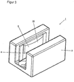
- FIG. 3 shows in a perspective view of the guide device 1 after installation, so that for example the spring elements 8, 9 are no longer visible due to the perspective of the drawing, but only the U-shaped Grundköper 3 with the receiving elements 4, 5 and in the receiving elements. 4 5 inserted guide elements 6, 7. From this view, it is already clear that the spherical contact surfaces 39 opposite protrude the legs 15, 16 of the base body 3 and in the intermediate space, formed by the two legs 15, 16 protrude.
- the guide elements 6, 7 are pressed by the spring elements 8, 9 in the uppermost position and only at the introduction of the building element they are apart and on the beveled guide surfaces 31, 35 simultaneously against the Spring force pressed down so that the guide elements 6, 7 can always rest under bias on the building elements.
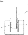
- FIG. 4 shows in a side view, the guide device 1 after the assembly and a recorded building element 40, which is in direct contact with the spherical contact surface 39 of the two guide elements 6, 7, so that a maintenance-free guidance is present solely by the existing spring force without any Nachjustier products.
- FIG. 5 shows in a plan view of the guide device 1 with base 3 and building element 40, which is received between the convex contact surfaces 39 clamped, which bear against the building element 40 under spring tension.
Landscapes
- Engineering & Computer Science (AREA)
- Mechanical Engineering (AREA)
- Buildings Adapted To Withstand Abnormal External Influences (AREA)
- Power-Operated Mechanisms For Wings (AREA)
Claims (12)
- Dispositif de guidage (1) pour éléments de bâtiment plats coulissants (40), en particulier des portes, des fenêtres, des cloisons ou des volets, comprenant au moins une plaque de fermeture (2) avec un corps de base (3) présentant une section en forme de U et avec des éléments de guidage (6, 7),
caractérisé en ce que
les éléments de guidage (6, 7) présentent une surface de guidage en biais (35) et s'appuient avec cette surface de guidage contre une surface de guidage (31) correspondante d'un élément de logement (4, 5) du dispositif de guidage ou du corps de base (3) et sont montés sous précontrainte élastique à l'intérieur de l'élément de logement (4, 5) ou du corps de base (3), dans lequel par l'intermédiaire de la précontrainte élastique un déplacement vertical est effectué et permet en même temps un déplacement horizontal au-dessus des surfaces de guidage en biais (31, 35) les uns sur les autres. - Dispositif de guidage (1) selon la revendication 1,
caractérisé en ce que
les éléments de guidage (6, 7) sont chacun déplaçables verticalement vers le haut par le biais d'au moins un élément élastique (8, 9). - Dispositif de guidage (1) selon une des revendications 1 ou 2,
caractérisé en ce que
les éléments de guidage (6, 7) sont munis d'un tenon de guidage (36, 37) au niveau des surfaces frontales. - Dispositif de guidage (1) selon une des revendications 1 à 3,
caractérisé en ce que
les éléments de guidage (6, 7) sont logés avec leurs tenons de guidage (36, 37) respectivement dans une rainure (32) du corps de base (3) ou des éléments de logement (4, 5). - Dispositif de guidage (1) selon une des revendications 1 à 4,
caractérisé en ce que
les éléments de guidage (6, 7) sont réalisés de manière sphérique sur leur face orientée vers les éléments de paroi. - Dispositif de guidage (1) selon une des revendications 1 à 5,
caractérisé en ce que
le corps de base (3) peut être appliqué sur la plaque de fermeture (2) et être vissé sur le support à l'aide de vis, ou en ce que le corps de base (3), les éléments élastiques (6, 7) et la plaque de fermeture (2) peuvent être prémontés et être vissés sur le support à l'aide de vis. - Dispositif de guidage (1) selon une des revendications 1 à 6, caractérisé en ce que
le corps de base (3) est réalisé d'un seul tenant et présente une section en forme de U, un évidement rectangulaire (17) orienté vers l'intérieur étant présent respectivement dans les branches latérales (15, 16). - Dispositif de guidage (1) selon la revendication 7,
caractérisé en ce que
l'évidement (30) présente une surface de guidage en biais (31) et deux rainures (32) s'étendant parallèlement vers la surface de guidage (31). - Dispositif de guidage (1) selon une des revendications 1 à 8,
caractérisé en ce que
le corps de base (3) est réalisé en plusieurs parties et présente une section en forme de U, un évidement rectangulaire (17) orienté vers l'intérieur, dans lequel un élément de logement (4, 5) peut être inséré, étant présent respectivement dans les branches latérales (15, 16). - Dispositif de guidage (1) selon une ou plusieurs des revendications 1 à 9,
caractérisé en ce que
les élément de logement (4, 5) présentent respectivement sur les surfaces frontales une traverse de guidage (19, 20) qui est logée respectivement dans une rainure (18) du corps de base (3). - Dispositif de guidage (1) selon la revendication 10,
caractérisé en ce que
les éléments de logement (4, 5) présentent un évidement rectangulaire (30) avec une surface de guidage en biais et deux rainures (32) s'étendant parallèlement vers la surface de guidage (31). - Dispositif de guidage (1) selon une ou plusieurs des revendications 1 à 11,
caractérisé en ce que
la plaque de fermeture (2) présente au moins deux poches de logement (13, 14) pour les éléments élastiques (8, 9).
Priority Applications (1)
| Application Number | Priority Date | Filing Date | Title |
|---|---|---|---|
| PL17160389T PL3222803T3 (pl) | 2016-03-15 | 2017-03-10 | Prowadnica do płaskich, przesuwnych elementów budynku |
Applications Claiming Priority (1)
| Application Number | Priority Date | Filing Date | Title |
|---|---|---|---|
| DE102016003099.2A DE102016003099B3 (de) | 2016-03-15 | 2016-03-15 | Führungseinrichtung für flächige, verschiebbare Gebäudeelemente |
Publications (2)
| Publication Number | Publication Date |
|---|---|
| EP3222803A1 EP3222803A1 (fr) | 2017-09-27 |
| EP3222803B1 true EP3222803B1 (fr) | 2018-03-21 |
Family
ID=58266515
Family Applications (1)
| Application Number | Title | Priority Date | Filing Date |
|---|---|---|---|
| EP17160389.7A Active EP3222803B1 (fr) | 2016-03-15 | 2017-03-10 | Dispositif de guidage pour des éléments de bâtiment plats, coulissants |
Country Status (4)
| Country | Link |
|---|---|
| EP (1) | EP3222803B1 (fr) |
| DE (1) | DE102016003099B3 (fr) |
| ES (1) | ES2675145T3 (fr) |
| PL (1) | PL3222803T3 (fr) |
Cited By (1)
| Publication number | Priority date | Publication date | Assignee | Title |
|---|---|---|---|---|
| US20240344377A1 (en) * | 2022-10-12 | 2024-10-17 | Kohler Co. | Removable Center Guide for Shower Doors |
Families Citing this family (1)
| Publication number | Priority date | Publication date | Assignee | Title |
|---|---|---|---|---|
| CN113605799B (zh) * | 2021-07-20 | 2025-05-30 | 福建省德牧卫浴科技有限公司 | 一种移门导向组件和移门装置 |
Family Cites Families (6)
| Publication number | Priority date | Publication date | Assignee | Title |
|---|---|---|---|---|
| DE59509120D1 (de) * | 1994-03-28 | 2001-05-03 | Hawa Ag Mettmenstetten | Vorrichtung zur Führung von verschiebbaren Elementen |
| JPH07331949A (ja) * | 1994-06-14 | 1995-12-19 | Yuusuten:Kk | 引き戸の開閉支持構造 |
| EP1394347B1 (fr) * | 2002-09-02 | 2006-06-21 | Hawa Ag | Dispositif de guidage pour partitions coulissantes et élément de guidage élastique |
| DE102007029557C5 (de) * | 2007-06-26 | 2020-03-19 | Geze Gmbh | Führungsvorrichtung für einen Schiebeflügel |
| DE102009057248A1 (de) * | 2009-12-08 | 2011-06-09 | Dorma Gmbh + Co. Kg | Führungselement für eine Schiebetür, insbesondere eine Ganzglasschiebetür |
| DE202012004752U1 (de) * | 2012-05-14 | 2013-08-20 | Gebr. Willach Gmbh | Bodenführung für Glasschiebetüren |
-
2016
- 2016-03-15 DE DE102016003099.2A patent/DE102016003099B3/de not_active Expired - Fee Related
-
2017
- 2017-03-10 EP EP17160389.7A patent/EP3222803B1/fr active Active
- 2017-03-10 PL PL17160389T patent/PL3222803T3/pl unknown
- 2017-03-10 ES ES17160389.7T patent/ES2675145T3/es active Active
Non-Patent Citations (1)
| Title |
|---|
| None * |
Cited By (1)
| Publication number | Priority date | Publication date | Assignee | Title |
|---|---|---|---|---|
| US20240344377A1 (en) * | 2022-10-12 | 2024-10-17 | Kohler Co. | Removable Center Guide for Shower Doors |
Also Published As
| Publication number | Publication date |
|---|---|
| EP3222803A1 (fr) | 2017-09-27 |
| ES2675145T3 (es) | 2018-07-09 |
| DE102016003099B3 (de) | 2017-08-31 |
| PL3222803T3 (pl) | 2018-08-31 |
Similar Documents
| Publication | Publication Date | Title |
|---|---|---|
| EP3452680B1 (fr) | Dispositif d'étanchéité | |
| EP3380692B1 (fr) | Dispositif de paroi coulissante avec élément de recouvrement | |
| EP2992156B1 (fr) | Système de guidage d'une porte coulissante, porte coulissante et meuble | |
| DE102017117573B4 (de) | Anordnung einer Dichtungsvorrichtung sowie damit versehene Schiebetür | |
| DE4445793C1 (de) | Fenster, Tür od. ähnlicher Öffnungsverschluß | |
| EP3222803B1 (fr) | Dispositif de guidage pour des éléments de bâtiment plats, coulissants | |
| EP4027836B1 (fr) | Glissière de tiroir | |
| EP4071328B1 (fr) | Dispositif à paroi coulissante pourvu d'élément de recouvrement | |
| EP3201413B1 (fr) | Ensemble de ferrures | |
| EP3859105B1 (fr) | Dispositif de fermeture | |
| EP2951374A1 (fr) | Pièce coulissante servant à guider une partie de meuble dans un sens de guidage sur une glissière et ferrure de meuble | |
| EP2402546A2 (fr) | Installation de porte | |
| EP3371402B1 (fr) | Agencement de ferrure pour élément à soulèvement et coulissement avec elément de réglage monté sur cadre | |
| DE10323695B4 (de) | Schiebetürprofil | |
| DE19742780B4 (de) | Laufrollen- und Führungsanordnung für Schiebetüren | |
| DE102018200582B3 (de) | Teleskopschiebetürsystem | |
| EP3085281B1 (fr) | Élement coulissant destine a ranger par coulissement un rideau ou une bache | |
| DE102012222200B4 (de) | Bewegungsbegrenzer für einen Flügel einer Schiebetür | |
| EP2504513A1 (fr) | Mécanisme de roulement pour une porte coulissante | |
| WO2025153412A2 (fr) | Dispositif d'étanchéité | |
| EP1038488A2 (fr) | Cloison de douche | |
| DE202004005162U1 (de) | Bodendichtung mit Federband | |
| EP3516149B1 (fr) | Combinaison d'un châssis de battant et d'un châssis dormant | |
| EP4174268A1 (fr) | Ferrure roulante de porte coulissante et agencement de porte coulissante associé | |
| DE102010030785B4 (de) | Schiebetüranlage |
Legal Events
| Date | Code | Title | Description |
|---|---|---|---|
| PUAI | Public reference made under article 153(3) epc to a published international application that has entered the european phase |
Free format text: ORIGINAL CODE: 0009012 |
|
| STAA | Information on the status of an ep patent application or granted ep patent |
Free format text: STATUS: THE APPLICATION HAS BEEN PUBLISHED |
|
| AK | Designated contracting states |
Kind code of ref document: A1 Designated state(s): AL AT BE BG CH CY CZ DE DK EE ES FI FR GB GR HR HU IE IS IT LI LT LU LV MC MK MT NL NO PL PT RO RS SE SI SK SM TR |
|
| AX | Request for extension of the european patent |
Extension state: BA ME |
|
| STAA | Information on the status of an ep patent application or granted ep patent |
Free format text: STATUS: REQUEST FOR EXAMINATION WAS MADE |
|
| 17P | Request for examination filed |
Effective date: 20170926 |
|
| RBV | Designated contracting states (corrected) |
Designated state(s): AL AT BE BG CH CY CZ DE DK EE ES FI FR GB GR HR HU IE IS IT LI LT LU LV MC MK MT NL NO PL PT RO RS SE SI SK SM TR |
|
| GRAP | Despatch of communication of intention to grant a patent |
Free format text: ORIGINAL CODE: EPIDOSNIGR1 |
|
| STAA | Information on the status of an ep patent application or granted ep patent |
Free format text: STATUS: GRANT OF PATENT IS INTENDED |
|
| RIC1 | Information provided on ipc code assigned before grant |
Ipc: E05D 15/06 20060101AFI20171031BHEP |
|
| INTG | Intention to grant announced |
Effective date: 20171204 |
|
| GRAS | Grant fee paid |
Free format text: ORIGINAL CODE: EPIDOSNIGR3 |
|
| GRAA | (expected) grant |
Free format text: ORIGINAL CODE: 0009210 |
|
| STAA | Information on the status of an ep patent application or granted ep patent |
Free format text: STATUS: THE PATENT HAS BEEN GRANTED |
|
| AK | Designated contracting states |
Kind code of ref document: B1 Designated state(s): AL AT BE BG CH CY CZ DE DK EE ES FI FR GB GR HR HU IE IS IT LI LT LU LV MC MK MT NL NO PL PT RO RS SE SI SK SM TR |
|
| REG | Reference to a national code |
Ref country code: GB Ref legal event code: FG4D Free format text: NOT ENGLISH |
|
| REG | Reference to a national code |
Ref country code: CH Ref legal event code: EP |
|
| REG | Reference to a national code |
Ref country code: AT Ref legal event code: REF Ref document number: 981291 Country of ref document: AT Kind code of ref document: T Effective date: 20180415 |
|
| REG | Reference to a national code |
Ref country code: IE Ref legal event code: FG4D Free format text: LANGUAGE OF EP DOCUMENT: GERMAN |
|
| REG | Reference to a national code |
Ref country code: DE Ref legal event code: R096 Ref document number: 502017000012 Country of ref document: DE |
|
| REG | Reference to a national code |
Ref country code: ES Ref legal event code: FG2A Ref document number: 2675145 Country of ref document: ES Kind code of ref document: T3 Effective date: 20180709 |
|
| REG | Reference to a national code |
Ref country code: NL Ref legal event code: FP |
|
| PG25 | Lapsed in a contracting state [announced via postgrant information from national office to epo] |
Ref country code: CY Free format text: LAPSE BECAUSE OF FAILURE TO SUBMIT A TRANSLATION OF THE DESCRIPTION OR TO PAY THE FEE WITHIN THE PRESCRIBED TIME-LIMIT Effective date: 20180321 Ref country code: NO Free format text: LAPSE BECAUSE OF FAILURE TO SUBMIT A TRANSLATION OF THE DESCRIPTION OR TO PAY THE FEE WITHIN THE PRESCRIBED TIME-LIMIT Effective date: 20180621 Ref country code: LT Free format text: LAPSE BECAUSE OF FAILURE TO SUBMIT A TRANSLATION OF THE DESCRIPTION OR TO PAY THE FEE WITHIN THE PRESCRIBED TIME-LIMIT Effective date: 20180321 Ref country code: HR Free format text: LAPSE BECAUSE OF FAILURE TO SUBMIT A TRANSLATION OF THE DESCRIPTION OR TO PAY THE FEE WITHIN THE PRESCRIBED TIME-LIMIT Effective date: 20180321 Ref country code: FI Free format text: LAPSE BECAUSE OF FAILURE TO SUBMIT A TRANSLATION OF THE DESCRIPTION OR TO PAY THE FEE WITHIN THE PRESCRIBED TIME-LIMIT Effective date: 20180321 |
|
| REG | Reference to a national code |
Ref country code: LT Ref legal event code: MG4D |
|
| PG25 | Lapsed in a contracting state [announced via postgrant information from national office to epo] |
Ref country code: LV Free format text: LAPSE BECAUSE OF FAILURE TO SUBMIT A TRANSLATION OF THE DESCRIPTION OR TO PAY THE FEE WITHIN THE PRESCRIBED TIME-LIMIT Effective date: 20180321 Ref country code: SE Free format text: LAPSE BECAUSE OF FAILURE TO SUBMIT A TRANSLATION OF THE DESCRIPTION OR TO PAY THE FEE WITHIN THE PRESCRIBED TIME-LIMIT Effective date: 20180321 Ref country code: BG Free format text: LAPSE BECAUSE OF FAILURE TO SUBMIT A TRANSLATION OF THE DESCRIPTION OR TO PAY THE FEE WITHIN THE PRESCRIBED TIME-LIMIT Effective date: 20180621 Ref country code: GR Free format text: LAPSE BECAUSE OF FAILURE TO SUBMIT A TRANSLATION OF THE DESCRIPTION OR TO PAY THE FEE WITHIN THE PRESCRIBED TIME-LIMIT Effective date: 20180622 Ref country code: RS Free format text: LAPSE BECAUSE OF FAILURE TO SUBMIT A TRANSLATION OF THE DESCRIPTION OR TO PAY THE FEE WITHIN THE PRESCRIBED TIME-LIMIT Effective date: 20180321 |
|
| PG25 | Lapsed in a contracting state [announced via postgrant information from national office to epo] |
Ref country code: MT Free format text: LAPSE BECAUSE OF FAILURE TO SUBMIT A TRANSLATION OF THE DESCRIPTION OR TO PAY THE FEE WITHIN THE PRESCRIBED TIME-LIMIT Effective date: 20180321 |
|
| PG25 | Lapsed in a contracting state [announced via postgrant information from national office to epo] |
Ref country code: EE Free format text: LAPSE BECAUSE OF FAILURE TO SUBMIT A TRANSLATION OF THE DESCRIPTION OR TO PAY THE FEE WITHIN THE PRESCRIBED TIME-LIMIT Effective date: 20180321 Ref country code: AL Free format text: LAPSE BECAUSE OF FAILURE TO SUBMIT A TRANSLATION OF THE DESCRIPTION OR TO PAY THE FEE WITHIN THE PRESCRIBED TIME-LIMIT Effective date: 20180321 Ref country code: RO Free format text: LAPSE BECAUSE OF FAILURE TO SUBMIT A TRANSLATION OF THE DESCRIPTION OR TO PAY THE FEE WITHIN THE PRESCRIBED TIME-LIMIT Effective date: 20180321 |
|
| PG25 | Lapsed in a contracting state [announced via postgrant information from national office to epo] |
Ref country code: SM Free format text: LAPSE BECAUSE OF FAILURE TO SUBMIT A TRANSLATION OF THE DESCRIPTION OR TO PAY THE FEE WITHIN THE PRESCRIBED TIME-LIMIT Effective date: 20180321 Ref country code: SK Free format text: LAPSE BECAUSE OF FAILURE TO SUBMIT A TRANSLATION OF THE DESCRIPTION OR TO PAY THE FEE WITHIN THE PRESCRIBED TIME-LIMIT Effective date: 20180321 Ref country code: CZ Free format text: LAPSE BECAUSE OF FAILURE TO SUBMIT A TRANSLATION OF THE DESCRIPTION OR TO PAY THE FEE WITHIN THE PRESCRIBED TIME-LIMIT Effective date: 20180321 |
|
| PG25 | Lapsed in a contracting state [announced via postgrant information from national office to epo] |
Ref country code: PT Free format text: LAPSE BECAUSE OF FAILURE TO SUBMIT A TRANSLATION OF THE DESCRIPTION OR TO PAY THE FEE WITHIN THE PRESCRIBED TIME-LIMIT Effective date: 20180723 |
|
| REG | Reference to a national code |
Ref country code: DE Ref legal event code: R097 Ref document number: 502017000012 Country of ref document: DE |
|
| PLBE | No opposition filed within time limit |
Free format text: ORIGINAL CODE: 0009261 |
|
| STAA | Information on the status of an ep patent application or granted ep patent |
Free format text: STATUS: NO OPPOSITION FILED WITHIN TIME LIMIT |
|
| PG25 | Lapsed in a contracting state [announced via postgrant information from national office to epo] |
Ref country code: DK Free format text: LAPSE BECAUSE OF FAILURE TO SUBMIT A TRANSLATION OF THE DESCRIPTION OR TO PAY THE FEE WITHIN THE PRESCRIBED TIME-LIMIT Effective date: 20180321 |
|
| 26N | No opposition filed |
Effective date: 20190102 |
|
| PG25 | Lapsed in a contracting state [announced via postgrant information from national office to epo] |
Ref country code: MC Free format text: LAPSE BECAUSE OF FAILURE TO SUBMIT A TRANSLATION OF THE DESCRIPTION OR TO PAY THE FEE WITHIN THE PRESCRIBED TIME-LIMIT Effective date: 20180321 |
|
| PG25 | Lapsed in a contracting state [announced via postgrant information from national office to epo] |
Ref country code: LU Free format text: LAPSE BECAUSE OF NON-PAYMENT OF DUE FEES Effective date: 20190310 |
|
| PG25 | Lapsed in a contracting state [announced via postgrant information from national office to epo] |
Ref country code: IE Free format text: LAPSE BECAUSE OF NON-PAYMENT OF DUE FEES Effective date: 20190310 |
|
| PG25 | Lapsed in a contracting state [announced via postgrant information from national office to epo] |
Ref country code: TR Free format text: LAPSE BECAUSE OF FAILURE TO SUBMIT A TRANSLATION OF THE DESCRIPTION OR TO PAY THE FEE WITHIN THE PRESCRIBED TIME-LIMIT Effective date: 20180321 |
|
| PG25 | Lapsed in a contracting state [announced via postgrant information from national office to epo] |
Ref country code: IS Free format text: LAPSE BECAUSE OF FAILURE TO SUBMIT A TRANSLATION OF THE DESCRIPTION OR TO PAY THE FEE WITHIN THE PRESCRIBED TIME-LIMIT Effective date: 20180721 |
|
| PG25 | Lapsed in a contracting state [announced via postgrant information from national office to epo] |
Ref country code: HU Free format text: LAPSE BECAUSE OF FAILURE TO SUBMIT A TRANSLATION OF THE DESCRIPTION OR TO PAY THE FEE WITHIN THE PRESCRIBED TIME-LIMIT; INVALID AB INITIO Effective date: 20170310 |
|
| PG25 | Lapsed in a contracting state [announced via postgrant information from national office to epo] |
Ref country code: SI Free format text: LAPSE BECAUSE OF FAILURE TO SUBMIT A TRANSLATION OF THE DESCRIPTION OR TO PAY THE FEE WITHIN THE PRESCRIBED TIME-LIMIT Effective date: 20180321 |
|
| PG25 | Lapsed in a contracting state [announced via postgrant information from national office to epo] |
Ref country code: MK Free format text: LAPSE BECAUSE OF FAILURE TO SUBMIT A TRANSLATION OF THE DESCRIPTION OR TO PAY THE FEE WITHIN THE PRESCRIBED TIME-LIMIT Effective date: 20180321 |
|
| REG | Reference to a national code |
Ref country code: DE Ref legal event code: R082 Ref document number: 502017000012 Country of ref document: DE Representative=s name: SEYER & NOBBE PATENTANWAELTE PARTNERSCHAFTSGES, DE |
|
| PGFP | Annual fee paid to national office [announced via postgrant information from national office to epo] |
Ref country code: ES Payment date: 20250416 Year of fee payment: 9 |
|
| PGFP | Annual fee paid to national office [announced via postgrant information from national office to epo] |
Ref country code: IT Payment date: 20250331 Year of fee payment: 9 |
|
| PGFP | Annual fee paid to national office [announced via postgrant information from national office to epo] |
Ref country code: CH Payment date: 20250401 Year of fee payment: 9 |
|
| REG | Reference to a national code |
Ref country code: CH Ref legal event code: U11 Free format text: ST27 STATUS EVENT CODE: U-0-0-U10-U11 (AS PROVIDED BY THE NATIONAL OFFICE) Effective date: 20260401 |
|
| PGFP | Annual fee paid to national office [announced via postgrant information from national office to epo] |
Ref country code: GB Payment date: 20260324 Year of fee payment: 10 |
|
| PGFP | Annual fee paid to national office [announced via postgrant information from national office to epo] |
Ref country code: DE Payment date: 20260204 Year of fee payment: 10 |
|
| PGFP | Annual fee paid to national office [announced via postgrant information from national office to epo] |
Ref country code: AT Payment date: 20260319 Year of fee payment: 10 |
|
| PGFP | Annual fee paid to national office [announced via postgrant information from national office to epo] |
Ref country code: BE Payment date: 20260323 Year of fee payment: 10 |
|
| PGFP | Annual fee paid to national office [announced via postgrant information from national office to epo] |
Ref country code: NL Payment date: 20260323 Year of fee payment: 10 |
|
| PGFP | Annual fee paid to national office [announced via postgrant information from national office to epo] |
Ref country code: FR Payment date: 20260325 Year of fee payment: 10 |
|
| PGFP | Annual fee paid to national office [announced via postgrant information from national office to epo] |
Ref country code: PL Payment date: 20260205 Year of fee payment: 10 |