EP3222838A1 - Système de génération de puissance pour moteur à combustion interne - Google Patents
Système de génération de puissance pour moteur à combustion interne Download PDFInfo
- Publication number
- EP3222838A1 EP3222838A1 EP17160629.6A EP17160629A EP3222838A1 EP 3222838 A1 EP3222838 A1 EP 3222838A1 EP 17160629 A EP17160629 A EP 17160629A EP 3222838 A1 EP3222838 A1 EP 3222838A1
- Authority
- EP
- European Patent Office
- Prior art keywords
- power generation
- power
- instruction value
- turbocharger
- magnitude relationship
- Prior art date
- Legal status (The legal status is an assumption and is not a legal conclusion. Google has not performed a legal analysis and makes no representation as to the accuracy of the status listed.)
- Withdrawn
Links
- 238000010248 power generation Methods 0.000 title claims abstract description 294
- 238000002485 combustion reaction Methods 0.000 title claims abstract description 50
- 238000005086 pumping Methods 0.000 claims abstract description 17
- 230000008901 benefit Effects 0.000 description 19
- 101710186160 S-adenosylmethionine synthase 3 Proteins 0.000 description 17
- 230000005540 biological transmission Effects 0.000 description 2
- 230000007246 mechanism Effects 0.000 description 2
- 238000000034 method Methods 0.000 description 2
- 230000001133 acceleration Effects 0.000 description 1
- 239000003054 catalyst Substances 0.000 description 1
- 230000008859 change Effects 0.000 description 1
- 239000000470 constituent Substances 0.000 description 1
- 238000010586 diagram Methods 0.000 description 1
- 239000000446 fuel Substances 0.000 description 1
- 230000007704 transition Effects 0.000 description 1
- 238000011144 upstream manufacturing Methods 0.000 description 1
Images



Classifications
-
- F—MECHANICAL ENGINEERING; LIGHTING; HEATING; WEAPONS; BLASTING
- F01—MACHINES OR ENGINES IN GENERAL; ENGINE PLANTS IN GENERAL; STEAM ENGINES
- F01D—NON-POSITIVE DISPLACEMENT MACHINES OR ENGINES, e.g. STEAM TURBINES
- F01D5/00—Blades; Blade-carrying members; Heating, heat-insulating, cooling or antivibration means on the blades or the members
- F01D5/02—Blade-carrying members, e.g. rotors
- F01D5/04—Blade-carrying members, e.g. rotors for radial-flow machines or engines
-
- B—PERFORMING OPERATIONS; TRANSPORTING
- B60—VEHICLES IN GENERAL
- B60W—CONJOINT CONTROL OF VEHICLE SUB-UNITS OF DIFFERENT TYPE OR DIFFERENT FUNCTION; CONTROL SYSTEMS SPECIALLY ADAPTED FOR HYBRID VEHICLES; ROAD VEHICLE DRIVE CONTROL SYSTEMS FOR PURPOSES NOT RELATED TO THE CONTROL OF A PARTICULAR SUB-UNIT
- B60W10/00—Conjoint control of vehicle sub-units of different type or different function
- B60W10/04—Conjoint control of vehicle sub-units of different type or different function including control of propulsion units
- B60W10/06—Conjoint control of vehicle sub-units of different type or different function including control of propulsion units including control of combustion engines
-
- B—PERFORMING OPERATIONS; TRANSPORTING
- B60—VEHICLES IN GENERAL
- B60W—CONJOINT CONTROL OF VEHICLE SUB-UNITS OF DIFFERENT TYPE OR DIFFERENT FUNCTION; CONTROL SYSTEMS SPECIALLY ADAPTED FOR HYBRID VEHICLES; ROAD VEHICLE DRIVE CONTROL SYSTEMS FOR PURPOSES NOT RELATED TO THE CONTROL OF A PARTICULAR SUB-UNIT
- B60W10/00—Conjoint control of vehicle sub-units of different type or different function
- B60W10/04—Conjoint control of vehicle sub-units of different type or different function including control of propulsion units
- B60W10/08—Conjoint control of vehicle sub-units of different type or different function including control of propulsion units including control of electric propulsion units, e.g. motors or generators
-
- B—PERFORMING OPERATIONS; TRANSPORTING
- B60—VEHICLES IN GENERAL
- B60W—CONJOINT CONTROL OF VEHICLE SUB-UNITS OF DIFFERENT TYPE OR DIFFERENT FUNCTION; CONTROL SYSTEMS SPECIALLY ADAPTED FOR HYBRID VEHICLES; ROAD VEHICLE DRIVE CONTROL SYSTEMS FOR PURPOSES NOT RELATED TO THE CONTROL OF A PARTICULAR SUB-UNIT
- B60W10/00—Conjoint control of vehicle sub-units of different type or different function
- B60W10/30—Conjoint control of vehicle sub-units of different type or different function including control of auxiliary equipment, e.g. air-conditioning compressors or oil pumps
-
- B—PERFORMING OPERATIONS; TRANSPORTING
- B60—VEHICLES IN GENERAL
- B60W—CONJOINT CONTROL OF VEHICLE SUB-UNITS OF DIFFERENT TYPE OR DIFFERENT FUNCTION; CONTROL SYSTEMS SPECIALLY ADAPTED FOR HYBRID VEHICLES; ROAD VEHICLE DRIVE CONTROL SYSTEMS FOR PURPOSES NOT RELATED TO THE CONTROL OF A PARTICULAR SUB-UNIT
- B60W30/00—Purposes of road vehicle drive control systems not related to the control of a particular sub-unit, e.g. of systems using conjoint control of vehicle sub-units
- B60W30/18—Propelling the vehicle
- B60W30/188—Controlling power parameters of the driveline, e.g. determining the required power
- B60W30/1882—Controlling power parameters of the driveline, e.g. determining the required power characterised by the working point of the engine, e.g. by using engine output chart
-
- F—MECHANICAL ENGINEERING; LIGHTING; HEATING; WEAPONS; BLASTING
- F01—MACHINES OR ENGINES IN GENERAL; ENGINE PLANTS IN GENERAL; STEAM ENGINES
- F01D—NON-POSITIVE DISPLACEMENT MACHINES OR ENGINES, e.g. STEAM TURBINES
- F01D15/00—Adaptations of machines or engines for special use; Combinations of engines with devices driven thereby
- F01D15/10—Adaptations for driving, or combinations with, electric generators
-
- F—MECHANICAL ENGINEERING; LIGHTING; HEATING; WEAPONS; BLASTING
- F02—COMBUSTION ENGINES; HOT-GAS OR COMBUSTION-PRODUCT ENGINE PLANTS
- F02B—INTERNAL-COMBUSTION PISTON ENGINES; COMBUSTION ENGINES IN GENERAL
- F02B37/00—Engines characterised by provision of pumps driven at least for part of the time by exhaust
- F02B37/04—Engines with exhaust drive and other drive of pumps, e.g. with exhaust-driven pump and mechanically-driven second pump
- F02B37/10—Engines with exhaust drive and other drive of pumps, e.g. with exhaust-driven pump and mechanically-driven second pump at least one pump being alternatively or simultaneously driven by exhaust and other drive, e.g. by pressurised fluid from a reservoir or an engine-driven pump
-
- F—MECHANICAL ENGINEERING; LIGHTING; HEATING; WEAPONS; BLASTING
- F02—COMBUSTION ENGINES; HOT-GAS OR COMBUSTION-PRODUCT ENGINE PLANTS
- F02B—INTERNAL-COMBUSTION PISTON ENGINES; COMBUSTION ENGINES IN GENERAL
- F02B37/00—Engines characterised by provision of pumps driven at least for part of the time by exhaust
- F02B37/12—Control of the pumps
-
- F—MECHANICAL ENGINEERING; LIGHTING; HEATING; WEAPONS; BLASTING
- F02—COMBUSTION ENGINES; HOT-GAS OR COMBUSTION-PRODUCT ENGINE PLANTS
- F02B—INTERNAL-COMBUSTION PISTON ENGINES; COMBUSTION ENGINES IN GENERAL
- F02B39/00—Component parts, details, or accessories relating to, driven charging or scavenging pumps, not provided for in groups F02B33/00 - F02B37/00
- F02B39/02—Drives of pumps; Varying pump drive gear ratio
- F02B39/08—Non-mechanical drives, e.g. fluid drives having variable gear ratio
- F02B39/10—Non-mechanical drives, e.g. fluid drives having variable gear ratio electric
-
- F—MECHANICAL ENGINEERING; LIGHTING; HEATING; WEAPONS; BLASTING
- F02—COMBUSTION ENGINES; HOT-GAS OR COMBUSTION-PRODUCT ENGINE PLANTS
- F02B—INTERNAL-COMBUSTION PISTON ENGINES; COMBUSTION ENGINES IN GENERAL
- F02B63/00—Adaptations of engines for driving pumps, hand-held tools or electric generators; Portable combinations of engines with engine-driven devices
- F02B63/04—Adaptations of engines for driving pumps, hand-held tools or electric generators; Portable combinations of engines with engine-driven devices for electric generators
-
- F—MECHANICAL ENGINEERING; LIGHTING; HEATING; WEAPONS; BLASTING
- F02—COMBUSTION ENGINES; HOT-GAS OR COMBUSTION-PRODUCT ENGINE PLANTS
- F02D—CONTROLLING COMBUSTION ENGINES
- F02D29/00—Controlling engines, such controlling being peculiar to the devices driven thereby, the devices being other than parts or accessories essential to engine operation, e.g. controlling of engines by signals external thereto
- F02D29/06—Controlling engines, such controlling being peculiar to the devices driven thereby, the devices being other than parts or accessories essential to engine operation, e.g. controlling of engines by signals external thereto peculiar to engines driving electric generators
-
- F—MECHANICAL ENGINEERING; LIGHTING; HEATING; WEAPONS; BLASTING
- F02—COMBUSTION ENGINES; HOT-GAS OR COMBUSTION-PRODUCT ENGINE PLANTS
- F02D—CONTROLLING COMBUSTION ENGINES
- F02D41/00—Electrical control of supply of combustible mixture or its constituents
- F02D41/0002—Controlling intake air
- F02D41/0007—Controlling intake air for control of turbo-charged or super-charged engines
-
- F—MECHANICAL ENGINEERING; LIGHTING; HEATING; WEAPONS; BLASTING
- F02—COMBUSTION ENGINES; HOT-GAS OR COMBUSTION-PRODUCT ENGINE PLANTS
- F02D—CONTROLLING COMBUSTION ENGINES
- F02D41/00—Electrical control of supply of combustible mixture or its constituents
- F02D41/02—Circuit arrangements for generating control signals
- F02D41/14—Introducing closed-loop corrections
- F02D41/1401—Introducing closed-loop corrections characterised by the control or regulation method
- F02D41/1406—Introducing closed-loop corrections characterised by the control or regulation method with use of a optimisation method, e.g. iteration
-
- B—PERFORMING OPERATIONS; TRANSPORTING
- B60—VEHICLES IN GENERAL
- B60W—CONJOINT CONTROL OF VEHICLE SUB-UNITS OF DIFFERENT TYPE OR DIFFERENT FUNCTION; CONTROL SYSTEMS SPECIALLY ADAPTED FOR HYBRID VEHICLES; ROAD VEHICLE DRIVE CONTROL SYSTEMS FOR PURPOSES NOT RELATED TO THE CONTROL OF A PARTICULAR SUB-UNIT
- B60W20/00—Control systems specially adapted for hybrid vehicles
-
- F—MECHANICAL ENGINEERING; LIGHTING; HEATING; WEAPONS; BLASTING
- F02—COMBUSTION ENGINES; HOT-GAS OR COMBUSTION-PRODUCT ENGINE PLANTS
- F02B—INTERNAL-COMBUSTION PISTON ENGINES; COMBUSTION ENGINES IN GENERAL
- F02B37/00—Engines characterised by provision of pumps driven at least for part of the time by exhaust
- F02B37/12—Control of the pumps
- F02B37/18—Control of the pumps by bypassing exhaust from the inlet to the outlet of turbine or to the atmosphere
-
- F—MECHANICAL ENGINEERING; LIGHTING; HEATING; WEAPONS; BLASTING
- F02—COMBUSTION ENGINES; HOT-GAS OR COMBUSTION-PRODUCT ENGINE PLANTS
- F02D—CONTROLLING COMBUSTION ENGINES
- F02D2250/00—Engine control related to specific problems or objectives
- F02D2250/18—Control of the engine output torque
- F02D2250/24—Control of the engine output torque by using an external load, e.g. a generator
-
- F—MECHANICAL ENGINEERING; LIGHTING; HEATING; WEAPONS; BLASTING
- F05—INDEXING SCHEMES RELATING TO ENGINES OR PUMPS IN VARIOUS SUBCLASSES OF CLASSES F01-F04
- F05D—INDEXING SCHEME FOR ASPECTS RELATING TO NON-POSITIVE-DISPLACEMENT MACHINES OR ENGINES, GAS-TURBINES OR JET-PROPULSION PLANTS
- F05D2220/00—Application
- F05D2220/40—Application in turbochargers
-
- Y—GENERAL TAGGING OF NEW TECHNOLOGICAL DEVELOPMENTS; GENERAL TAGGING OF CROSS-SECTIONAL TECHNOLOGIES SPANNING OVER SEVERAL SECTIONS OF THE IPC; TECHNICAL SUBJECTS COVERED BY FORMER USPC CROSS-REFERENCE ART COLLECTIONS [XRACs] AND DIGESTS
- Y02—TECHNOLOGIES OR APPLICATIONS FOR MITIGATION OR ADAPTATION AGAINST CLIMATE CHANGE
- Y02T—CLIMATE CHANGE MITIGATION TECHNOLOGIES RELATED TO TRANSPORTATION
- Y02T10/00—Road transport of goods or passengers
- Y02T10/10—Internal combustion engine [ICE] based vehicles
- Y02T10/12—Improving ICE efficiencies
Definitions
- the present invention relates to a power generation system for an internal combustion engine.
- the invention provides a power generation system for an internal combustion engine that can select efficient power generation in consideration of a pumping loss of the internal combustion engine between power generation performed by a turbocharger with a power generation function and power generation performed by an alternator.
- a power generation system for an internal combustion engine includes: a turbocharger capable of generating power by performing a turbocharger power generation using rotation of a turbine provided in an exhaust passage of the internal combustion engine; a generated power calculation unit configured to calculate a first power generation instruction value, the first power generation instruction value being a value of generated power required for the turbocharger; and a power generation control unit configured to control the turbocharger to perform the turbocharger power generation based on the first power generation instruction value.
- the generated power calculation unit is configured to determine, based on an operational state of the internal combustion engine, whether or not a magnitude relationship is satisfied, the magnitude relationship being a relationship in which generated power of the turbocharger power generation is larger than an increase amount of a pumping loss of the internal combustion engine resulting from the turbocharger power generation, and the generated power calculation unit is configured to calculate the first power generation instruction value larger when the magnitude relationship is satisfied than when the magnitude relationship is not satisfied.
- the power generation system may include an alternator capable of generating power using output of the internal combustion engine; and a required generated power calculation unit configured to calculate required generated power required to the internal combustion engine.
- the generated power calculation unit may be configured to calculate the first power generation instruction value and a second power generation instruction value required for the alternator such that the required generated power is generated through the turbocharger power generation and alternator power generation performed by the alternator, and may be configured to calculate the first power generation instruction value and the second power generation instruction value such that a ratio of the first power generation instruction value to the second power generation instruction value is larger when the magnitude relationship is satisfied than when the magnitude relationship is not satisfied.
- the power generation control unit may be configured to control the turbocharger to perform the turbocharger power generation based on the first power generation instruction value and control the alternator to perform the alternator power generation based on the second power generation instruction value.
- the generated power calculation unit may be configured to calculate the first power generation instruction value and the second power generation instruction value such that a ratio of the first power generation instruction value to a first power generation upper limit value at which power is capable of being generated through the turbocharger power generation is larger when the magnitude relationship is satisfied than when the magnitude relationship is not satisfied, and a ratio of the second power generation instruction value to a second power generation upper limit value at which power is capable of being generated through the alternator power generation is smaller when the magnitude relationship is satisfied than when the magnitude relationship is not satisfied.
- the operational state of the internal combustion engine is the operational state where the magnitude relationship in which the generated power of the turbocharger power generation is larger than the loss increase amount of the pumping loss of the internal combustion engine resulting from the turbocharger power generation is satisfied
- an advantage in the energy balance is obtained by performing the turbocharger power generation.
- the turbocharger power generation is performed in the case of the operational state where the magnitude relationship is not satisfied, there is instead a loss in the energy balance and there is no advantage. Therefore, it is more desirable to limit the turbocharger power generation.
- the ratio of the first power generation instruction value to the first power generation upper limit value resulting from the turbocharger power generation becomes larger, and the ratio of the second power generation instruction value to the second power generation upper limit value resulting from alternator power generation becomes smaller.
- the load factor of the turbocharger power generation becomes higher, and the load factor of the alternator power generation becomes lower.
- the generated power calculation unit may be configured to calculate the first power generation upper limit value as the first power generation instruction value and a value obtained by subtracting the first power generation upper limit value from the required generated power as the second power generation instruction value, when the magnitude relationship is satisfied.
- the ratio of the first power generation instruction value to the first power generation upper limit value of the turbocharger power generation is maximized, and the insufficient amount of the required generated power that is insufficient only through the turbocharger power generation is compensated for through the alternator power generation.
- the generated power calculation unit may be configured to calculate the second power generation upper limit value as the second power generation instruction value and a value obtained by subtracting the second power generation upper limit value from the required generated power as the first power generation instruction value, when the magnitude relationship is not satisfied.
- the ratio of the second power generation instruction value to the second power generation upper limit value of the alternator is maximized, and the insufficient amount of the required generated power that is insufficient only through the alternator power generation is compensated for through the turbocharger power generation.
- the generated power calculation unit may be configured to calculate the first power generation upper limit value of the turbocharger power generation as the first power generation instruction value and the second power generation upper limit value of the alternator power generation as the second power generation instruction value, irrespective of the magnitude relationship, when a total of the first power generation upper limit value and the second power generation upper limit value is smaller than the required generated power.
- the shortage of the generated power to the required generated power can be reduced as much as possible.
- the generated power calculation unit may be configured to determine whether or not the magnitude relationship is satisfied based on whether or not the first power generation upper limit value is larger than the increase amount of the pumping loss.
- the generated power calculation unit may be configured to determine the magnitude relationship, using the first power generation upper limit value and the increase amount of the pumping loss that are respectively determined corresponding to the output of the internal combustion engine when the magnitude relationship is determined.
- an increase in the pumping loss resulting from the turbocharger power generation is taken into consideration, and the respective generated powers of the turbocharger power generation and the alternator power generation are distributed to the required generated power required for the internal combustion engine.
- efficient power generation suitable for the operational state of the internal combustion engine can be selected.
- an internal combustion engine 1 is constituted as an in-line 4-cylinder type spark-ignition internal combustion engine in which four cylinders 2 are lined up, and is mounted on a vehicle (not illustrated).
- the internal combustion engine 1 is provided with a motor-assisted turbocharger (MAT) 3 with a power generation function.
- the MAT 3 has a turbine 4 and a compressor 5, and a rotating shaft 6 that couples the turbine 4 and the compressor 5 is provided with a three-phase AC type motor generator 7 that functions as an electric motor and a generator.
- the MAT 3 can make the motor generator 7 function as an electric motor to assist in supercharging, or can make the motor generator 7 function as a generator to convert exhaust energy into power.
- An intake passage 10 and an exhaust passage 11 are connected to the respective cylinders 2 of the internal combustion engine 1.
- the intake passage 10 is provided with an air cleaner 12 that filters intake air, the compressor 5 of the MAT 3, an intercooler 13 that cools the air compressed by the compressor 5, and a throttle valve 14 that adjusts the amount of intake air.
- the intake passage 10 includes an intake manifold 10a that branches to the respective cylinders 2 downstream from the throttle valve 14.
- the exhaust passage 11 Includes an intake manifold 11a that collect exhaust gas of the respective cylinders 2, the turbine 4 of the MAT 3 is provided in a collection portion downstream from the intake manifold 11a, and an exhaust gas purifying catalyst 16 is provided downstream from the turbine 4. Additionally, the exhaust passage 11 is provided with a bypass passage 17 that connects the upstream and the downstream of the turbine 4 of the MAT 3 together and bypasses the turbine 4. The bypass passage 17 is opened and closed by a waist gate valve 18. The supercharging pressure of the internal combustion engine 1 is adjusted by the waist gate valve 18.
- the internal combustion engine 1 is provided with an alternator 20 capable of generating power using the output thereof.
- the output of a crankshaft 19 is transmitted to the alternator 20 via a belt transmission mechanism 21.
- the alternator 20 is electrically connected to a vehicle-mounted battery 25 with a rated voltage of 12 V.
- the motor generator 7 of the MAT 3 is AC-connected to a MAT inverter 26, and the MAT inverter 26 is connected to a MAT battery 27 with a rated of 42 V.
- the vehicle-mounted battery 25 and the MAT battery 27 are connected together via a DC/DC converter 28.
- the control of the internal combustion engine 1 is performed by an engine electronic control unit (engine ECU) 30 constituted as a computer.
- the engine ECU 30 also performs the basic operation control of the internal combustion engine 1, such as controlling the opening degree of the throttle valve 14 and controlling the amount fuel injected in an interlocking manner the control of the opening degree thereof, and performs the control of accessories of the internal combustion engine 1, such as controlling the generated power of the alternator 20.
- the engine ECU 30 performs the supercharging control of operates the MAT 3 and the waist gate valve 18, respectively, to adjust the supercharging pressure of the internal combustion engine 1.
- the control of the MAT 3 is directly performed by a MAT electronic control unit (MATECU) 31 connected to be capable of communicating with the engine ECU 30. That is, the engine ECU 30 instructs the MATECU 31 about various kinds of information, thereby directly controlling the MAT 3.
- MATECU MAT electronic control unit
- the supercharging auxiliary control of making the motor generator 7 of the MAT 3 function as an electric motor, and the power generation control of making the motor generator 7 function as a generator are included in the control of the MAT 3.
- the supercharging auxiliary control makes the motor generator 7 function as an electric motor in order to solve a turbo lag, for example, at the time of the acceleration transition of the vehicle, thereby assisting in supercharging.
- the power generation control makes the motor generator 7 function as a generator in a state where the waist gate valve 18 is closed, thereby converting the exhaust energy received by the turbine 4 into generated power.
- the power generation (hereinafter, referred to as turbocharger power generation) performed by the MAT 3 and the power generation (hereinafter referred to as alternator power generation) performed by the alternator 20 are performed by a power generation system S of the present embodiment having a configuration illustrated in FIG. 2 .
- the power generation system S includes an energy management unit 40 constituted with the engine ECU 30 and the MATECU 31, the MAT 3 and the alternator 20 that are controlled by the energy management unit 40, an SOC sensor 41 that detects the charge state of the vehicle-mounted battery 25 or the MAT battery 27, and a power sensor 42 for finding out the electrical load of a vehicle-mounted air-conditioner or lights.
- various kinds of information such as charge states of the respective batteries 25, 26 and the like that are output as output signals of the SOC sensor 41, a power state of vehicle-mounted equipment reflected in an output signal of the power sensor 42, a driving state of the vehicle, and an operational state of the internal combustion engine 1, are input to the energy management unit 40.
- the energy management unit 40 calculates required generated power required for the internal combustion engine 1 on the basis of the various kinds of input information, and calculates respective generated powers of the turbocharger power generation and the alternator power generation on the basis of the required generated power. Then, the energy management unit 40 controls the MAT 3 and the alternator 20 such that the turbocharger power generation and the alternator power generation are respectively performed with the calculated respective generated powers.
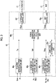
- the details of the energy management unit 40 are as illustrated in FIG. 3 .
- respective constituent units of the illustrated energy management unit 40 are logically configured inside these ECUs.
- a required generated power calculation unit 40a acquires a charge state Bsoc and an electrical load Pl of the vehicle-mounted battery 25 and the like with reference to the respective output signals of the SOC sensor 41 and the power sensor 42.
- the required generated power calculation unit 40a calculate a required generated power Tw required for the internal combustion engine 1 on the basis of the acquired charge state Bsoc and the acquired electrical load Pl, and sends the calculated required generated power Tw to a power generation instruction value calculation unit 40e.
- the calculation of the required generated power Tw may be performed, for example, by retrieving a calculation map that is stored in advance, or may be performed on the basis of a calculation formula with the charge state Bsoc and the electrical load Pl as variables.
- An alternator power generation upper limit value calculation unit 40b acquires an engine speed Ne with reference to an output signal of a crank angle sensor 43 (refer to FIG. 1 ), and calculates a rotational speed Nalt of the alternator 20 obtained by multiplying the engine speed Ne by a change gear ratio of the belt transmission mechanism 21. Then, the calculation unit 40b calculates an upper limit value Galt at which power is capable of being generated through the alternator power generation on the basis of the rotational speed Nalt of the alternator 20, and sends the calculated upper limit value to the power generation instruction value calculation unit 40e. Since a relationship between the rotational speed Nalt and the generated power of the alternator 20 is determined, the alternator power generation upper limit value calculation unit 40b calculates the upper limit value Galt, for example, on the basis of a predetermined calculation formula that is prepared in advance.
- a turbocharger power generation upper limit value calculation unit 40c acquires the engine speed Ne with reference to the output signal of the crank angle sensor 43 (refer to FIG. 1 ), and acquires an accelerator opening degree Acc with reference to an output signal of the accelerator opening degree sensor 44 (refer to FIG. 1 ). Then, the calculation unit 40c calculates engine output We as an operational state on the basis of the engine speed Ne and the accelerator opening degree Acc, calculates a power generation upper limit value Geeg on the basis of the engine output We, and sends the calculated power generation upper limit value to the gain/loss determination unit 40d and the power generation instruction value calculation unit 40e, respectively.
- the gain/loss determination unit 40d outputs a gain/loss determination value ⁇ showing the presence/absence of an advantage in the energy balance when the power generation upper limit value Geeg is compared with an increase amount of a pumping loss (hereinafter, also referred to as loss increase amount) of the internal combustion engine 1 resulting from the turbocharger power generation, and send the output gain/loss determination value to the power generation instruction value calculation unit 40e.
- the gain/loss determination value ⁇ is set "1" that means the presence of an advantage in the energy balance in a case where a magnitude relationship in which the power generation upper limit value Geeg is larger than the loss increase amount is satisfied, and is set to "0" that means the absence of an advantage in the energy balance in a case where the magnitude relationship is not satisfied.
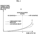
- the gain/loss determination unit 40d sets the value of the gain/loss determination value ⁇ , for example, on the basis of the determination map M illustrated in FIG. 4 .
- the determination map M has a structure in which engine power is set on a horizontal axis, the generated power is set on a vertical axis, the generated power per unit time resulting from the turbocharger power generation is illustrated by a curve line L1 that is a solid line, and the increase amount of the pumping loss per unit time is illustrated by a curve line L2 that is a dashed line.
- the two curve lines L1, L2 intersect each other at a branch point p of the engine power.
- the gain/loss determination unit 40d sets the value of the gain/loss determination value ⁇ to 1.
- the gain/loss determination unit 40d sets the value of the gain/loss determination value ⁇ to 0.
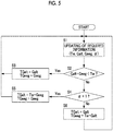
- the power generation instruction value calculation unit 40e calculates a power generation instruction value TGeeg to be required for the alternator 20 and a power generation instruction value TGalt to be required for the MAT 3, respectively, according to a processing routine illustrated in FIG. 5 to be described below using various kinds of information sent from the above-described respective units 40a to 40d.
- the power generation instruction value TGalt is sent to an alternator control unit 40f, and the power generation instruction value TGeeg is sent to the MAT control unit 40g.
- the alternator control unit 40f instructs the alternator 20 about the power generation instruction value TGalt, and makes the alternator perform the alternator power generation.
- the MAT control unit 40g instructs the MAT 3 about the power generation instruction value TGeeg, and make the MAT perform the turbocharger power generation.
- Step S1 the power generation instruction value calculation unit 40e reads required information including the required generated power Tw, the power generation upper limit value Galt, the power generation upper limit value Geeg, and the gain/loss determination value ⁇ , and updates these values.
- Step S2 the power generation instruction value calculation unit 40e determines whether or not a total of the power generation upper limit value Galt and the power generation upper limit value Geeg is smaller than the required generated power Tw, in other words, whether or not the required generated power Tw can be provided through the alternator power generation and the turbocharger power generation. In a case where the total of the power generation upper limit value Galt and the power generation upper limit value Geeg is smaller than the required generated power Tw, the required generated power Tw cannot be provided through the alternator power generation and the turbocharger power generation.
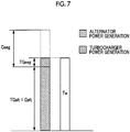
- Step S3 the power generation instruction value calculation unit 40e substitutes the power generation upper limit value Galt in the power generation instruction value TGalt, and substitutes the power generation upper limit value Geeg in the power generation instruction value TGeeg. That is, the power generation instruction value calculation unit 40e calculates the power generation upper limit value Galt as the power generation instruction value TGalt and calculates the power generation upper limit value Geeg as the power generation instruction value TGeeg. Accordingly, the respective power generation capacities of the alternator 20 and the MAT 3 that are determined in the current operational state of the internal combustion engine 1 is exhibited to the maximum. Hence, the shortage of the generated power to the required generated power Tw can be reduced as much as possible.
- Step S4 the power generation instruction value calculation unit 40e determines whether or not the gain/loss determination value ⁇ is "1", that is, whether or not there is any advantage in the energy balance due to the performance of the turbocharger power generation. In a case where there is an advantage in the energy balance, the processing proceeds to Step S5, and in a case where there is no advantage in the energy balance, the processing proceeds to Step S6.
- Step S5 the power generation instruction value calculation unit 40e substitutes a value, which is obtained by subtracting the power generation upper limit value Geeg from the required generated power Tw, in the power generation instruction value TGalt, and substitutes the power generation upper limit value Geeg in the power generation instruction value TGeeg, thereby calculating the power generation instruction value TGalt and the power generation instruction value TGeeg, respectively.
- the processing is returned to Step S1.
- a load factor of the turbocharger power generation is maximize by executing the processing of Step S5. That is, a ratio of the power generation instruction value TGeeg to the power generation upper limit value Geeg of the turbocharger power generation is maximized (100%). Then, the insufficient amount of the required generated power Tw that is insufficient only through the turbocharger power generation is compensated for through the alternator power generation.
- the power generation instruction value TGalt and the power generation instruction value TGeeg are calculated as follows.
- Step S6 in contrast to Step S5, the power generation instruction value calculation unit 40e substitutes the power generation upper limit value Galt in the power generation instruction value TGalt, and substituting a value, which is obtained by subtracting the power generation upper limit value Galt from the required generated power Tw, in the power generation instruction value TGeeg, thereby calculating the power generation instruction value TGalt and the power generation instruction value TGeeg, respectively.
- the processing is returned to Step S1.
- a load factor of the alternator power generation is maximize by executing the processing of Step S6. That is, a ratio of the power generation instruction value TGalt to the power generation upper limit value Galt of the alternator power generation is maximized (100%). Then, the insufficient amount of the required generated power Tw that is insufficient only through the alternator power generation is compensated for through the turbocharger power generation.
- the ratio of the power generation instruction value TGeeg to the power generation upper limit value Geeg of the turbocharger power generation becomes larger, and the ratio of the power generation instruction value TGalt to the power generation upper limit value Galt of the alternator power generation becomes smaller.
- an increase in the pumping loss resulting from the turbocharger power generation is taken into consideration as described above, and the power generation instruction value TGalt of the alternator power generation and the power generation instruction value TGeeg of the turbocharger power generation are calculated, respectively, so that the respective generated powers of the turbocharger power generation and the alternator power generation are distributed to the required generated power required for the internal combustion engine 1.
- efficient power generation suitable for the operational state of the internal combustion engine 1 can be selected.
- the invention is not limited to the above embodiment, and can be embodied in various forms within the scope of the concept of the invention.
- the load factor of the turbocharger power generation is set to 100% in a case where the magnitude relationship in which the generated power resulting from the performance of the turbocharger power generation is larger than the loss increase amount of the pumping loss of the internal combustion engine 1 is satisfied and there is an advantage in the energy balance.
- the invention can also be embodied, for example, in a form in which the load factor is smaller than 100%, such as setting the load factor of the turbocharger power generation to 80% in a case where the magnitude relationship is satisfied.
- the invention may be configured such that the power generation amount of the turbocharger power generation in a case where the magnitude relationship is satisfied becomes larger compared to a case where the magnitude relationship is not satisfied.
- the invention can also be embodied in a form in which the load factor is smaller than 100%, such as setting the load factor of the alternator power generation to 80%.
Landscapes
- Engineering & Computer Science (AREA)
- Mechanical Engineering (AREA)
- Chemical & Material Sciences (AREA)
- Combustion & Propulsion (AREA)
- General Engineering & Computer Science (AREA)
- Transportation (AREA)
- Automation & Control Theory (AREA)
- Supercharger (AREA)
- Control Of Vehicle Engines Or Engines For Specific Uses (AREA)
- Output Control And Ontrol Of Special Type Engine (AREA)
- Computer Hardware Design (AREA)
- Microelectronics & Electronic Packaging (AREA)
Applications Claiming Priority (1)
| Application Number | Priority Date | Filing Date | Title |
|---|---|---|---|
| JP2016051954A JP2017166405A (ja) | 2016-03-16 | 2016-03-16 | 内燃機関の発電システム |
Publications (1)
| Publication Number | Publication Date |
|---|---|
| EP3222838A1 true EP3222838A1 (fr) | 2017-09-27 |
Family
ID=58314137
Family Applications (1)
| Application Number | Title | Priority Date | Filing Date |
|---|---|---|---|
| EP17160629.6A Withdrawn EP3222838A1 (fr) | 2016-03-16 | 2017-03-13 | Système de génération de puissance pour moteur à combustion interne |
Country Status (7)
| Country | Link |
|---|---|
| US (1) | US9988979B2 (fr) |
| EP (1) | EP3222838A1 (fr) |
| JP (1) | JP2017166405A (fr) |
| KR (1) | KR20170107901A (fr) |
| CN (1) | CN107201939A (fr) |
| BR (1) | BR102017005258A2 (fr) |
| RU (1) | RU2659856C1 (fr) |
Families Citing this family (2)
| Publication number | Priority date | Publication date | Assignee | Title |
|---|---|---|---|---|
| JP6269330B2 (ja) * | 2014-06-06 | 2018-01-31 | トヨタ自動車株式会社 | 内燃機関の制御装置 |
| JP7414359B2 (ja) * | 2020-04-23 | 2024-01-16 | 日産自動車株式会社 | 内燃機関の制御方法及び内燃機関の制御装置 |
Citations (4)
| Publication number | Priority date | Publication date | Assignee | Title |
|---|---|---|---|---|
| EP0217537A1 (fr) * | 1985-08-28 | 1987-04-08 | Isuzu Motors Limited | Appareil de production de puissance à utiliser avec un moteur à combustion interne |
| JP2005151721A (ja) * | 2003-11-17 | 2005-06-09 | Nissan Motor Co Ltd | 車両の制御装置 |
| US20060113799A1 (en) * | 2004-12-01 | 2006-06-01 | Denso Corporation | Exhaust gas-driven generator system and method of controlling electrical system |
| JP2007327401A (ja) | 2006-06-07 | 2007-12-20 | Toyota Motor Corp | 車両における発電制御装置 |
Family Cites Families (9)
| Publication number | Priority date | Publication date | Assignee | Title |
|---|---|---|---|---|
| JPH0214415U (fr) * | 1988-07-13 | 1990-01-30 | ||
| JP4023421B2 (ja) * | 2003-09-10 | 2007-12-19 | トヨタ自動車株式会社 | 内燃機関の制御装置 |
| JP4241864B2 (ja) * | 2007-08-21 | 2009-03-18 | トヨタ自動車株式会社 | 車両駆動ユニットの制御装置 |
| JP2011072117A (ja) * | 2009-09-25 | 2011-04-07 | Mitsubishi Heavy Ind Ltd | 内燃機関システムおよび船舶 |
| JP5167326B2 (ja) * | 2010-11-05 | 2013-03-21 | 三菱重工業株式会社 | エンジン排気エネルギー回収装置 |
| JP2012219710A (ja) * | 2011-04-08 | 2012-11-12 | Ihi Corp | 車両用エンジン及び排気タービン発電機 |
| DE102011079036B4 (de) * | 2011-07-12 | 2018-12-20 | Mtu Friedrichshafen Gmbh | Brennkraftmaschinen-System, Wasserfahrzeug und Verfahren zum Betrieb eines Schiffsversorgungsnetzes mit einer Brennkraftmaschine |
| JP6156622B2 (ja) * | 2013-03-01 | 2017-07-05 | 三菱自動車工業株式会社 | 車両の制御装置 |
| JP6294646B2 (ja) * | 2013-12-04 | 2018-03-14 | 三菱重工業株式会社 | ターボコンパウンドシステムの制御装置 |
-
2016
- 2016-03-16 JP JP2016051954A patent/JP2017166405A/ja active Pending
-
2017
- 2017-03-08 KR KR1020170029251A patent/KR20170107901A/ko not_active Ceased
- 2017-03-13 CN CN201710147420.6A patent/CN107201939A/zh active Pending
- 2017-03-13 EP EP17160629.6A patent/EP3222838A1/fr not_active Withdrawn
- 2017-03-13 US US15/456,876 patent/US9988979B2/en not_active Expired - Fee Related
- 2017-03-14 RU RU2017108208A patent/RU2659856C1/ru not_active IP Right Cessation
- 2017-03-15 BR BR102017005258-3A patent/BR102017005258A2/pt not_active IP Right Cessation
Patent Citations (5)
| Publication number | Priority date | Publication date | Assignee | Title |
|---|---|---|---|---|
| EP0217537A1 (fr) * | 1985-08-28 | 1987-04-08 | Isuzu Motors Limited | Appareil de production de puissance à utiliser avec un moteur à combustion interne |
| JP2005151721A (ja) * | 2003-11-17 | 2005-06-09 | Nissan Motor Co Ltd | 車両の制御装置 |
| US20060113799A1 (en) * | 2004-12-01 | 2006-06-01 | Denso Corporation | Exhaust gas-driven generator system and method of controlling electrical system |
| JP2007327401A (ja) | 2006-06-07 | 2007-12-20 | Toyota Motor Corp | 車両における発電制御装置 |
| EP2024216A1 (fr) * | 2006-06-07 | 2009-02-18 | Toyota Jidosha Kabushiki Kaisha | Appareil de contrôle de génération électrique et procédé de contrôle dans un véhicule |
Also Published As
| Publication number | Publication date |
|---|---|
| KR20170107901A (ko) | 2017-09-26 |
| US9988979B2 (en) | 2018-06-05 |
| BR102017005258A2 (pt) | 2017-12-19 |
| JP2017166405A (ja) | 2017-09-21 |
| RU2659856C1 (ru) | 2018-07-04 |
| US20170268415A1 (en) | 2017-09-21 |
| CN107201939A (zh) | 2017-09-26 |
Similar Documents
| Publication | Publication Date | Title |
|---|---|---|
| US4894991A (en) | Control system for internal combustion engine with turbocharger | |
| EP3037640B1 (fr) | Dispositif de commande de système de turborécupérateur | |
| US9341145B2 (en) | Supercharged turbocompound hybrid engine apparatus | |
| EP2100787B1 (fr) | Machine de travail avec unité d'alimentation auxiliaire et gestion d'alimentation intelligente | |
| US4850193A (en) | Control system for turbocharger with rotary electric machine | |
| US20100107632A1 (en) | Hybrid powertrain and method for controlling a hybrid powertrain | |
| CN104340207B (zh) | 柴油发动机稳态和瞬变混合动力优化 | |
| CN104245453B (zh) | 车辆的控制装置 | |
| JPH08121183A (ja) | 電動・発電機付ターボチャージャの制御システム | |
| JPH03117628A (ja) | 回転電機付ターボチャージャの制御装置 | |
| EP2024216A1 (fr) | Appareil de contrôle de génération électrique et procédé de contrôle dans un véhicule | |
| JP2011051542A (ja) | ハイブリッド車両の制御装置 | |
| JP2008213833A (ja) | パワートレイン、その作動方法及びこのパワートレインを備えた原動機付き車両 | |
| US9988979B2 (en) | Power generation system for internal combustion engine | |
| JP2002038962A (ja) | ターボチャージャ付き内燃機関の制御装置 | |
| EP2711523A1 (fr) | Procédé de commande d'une turbine de puissance d'un appareil à moteur hybride | |
| JPH05280385A (ja) | ターボチャージャの制御装置 | |
| JP2020147195A (ja) | ハイブリッド車両およびハイブリッド車両の制御方法 | |
| JP7606357B2 (ja) | 過給システム | |
| JP7208602B2 (ja) | ハイブリッドシステム | |
| JP7208601B2 (ja) | ハイブリッドシステム | |
| JP3900124B2 (ja) | 電動過給機付エンジンを備えた車両の制御装置 | |
| JP2020157881A (ja) | ハイブリッド車両およびハイブリッド車両の制御方法 | |
| EP2886825B1 (fr) | Système de turborécupération amélioré, en particulier dans le domaine des véhicules industriels | |
| JP6028342B2 (ja) | ハイブリッド車両 |
Legal Events
| Date | Code | Title | Description |
|---|---|---|---|
| PUAI | Public reference made under article 153(3) epc to a published international application that has entered the european phase |
Free format text: ORIGINAL CODE: 0009012 |
|
| STAA | Information on the status of an ep patent application or granted ep patent |
Free format text: STATUS: REQUEST FOR EXAMINATION WAS MADE |
|
| 17P | Request for examination filed |
Effective date: 20170413 |
|
| AK | Designated contracting states |
Kind code of ref document: A1 Designated state(s): AL AT BE BG CH CY CZ DE DK EE ES FI FR GB GR HR HU IE IS IT LI LT LU LV MC MK MT NL NO PL PT RO RS SE SI SK SM TR |
|
| AX | Request for extension of the european patent |
Extension state: BA ME |
|
| GRAP | Despatch of communication of intention to grant a patent |
Free format text: ORIGINAL CODE: EPIDOSNIGR1 |
|
| STAA | Information on the status of an ep patent application or granted ep patent |
Free format text: STATUS: GRANT OF PATENT IS INTENDED |
|
| INTG | Intention to grant announced |
Effective date: 20180601 |
|
| STAA | Information on the status of an ep patent application or granted ep patent |
Free format text: STATUS: THE APPLICATION IS DEEMED TO BE WITHDRAWN |
|
| 18D | Application deemed to be withdrawn |
Effective date: 20181012 |