EP3223586B1 - Plaque de cuisson - Google Patents
Plaque de cuisson Download PDFInfo
- Publication number
- EP3223586B1 EP3223586B1 EP17157799.2A EP17157799A EP3223586B1 EP 3223586 B1 EP3223586 B1 EP 3223586B1 EP 17157799 A EP17157799 A EP 17157799A EP 3223586 B1 EP3223586 B1 EP 3223586B1
- Authority
- EP
- European Patent Office
- Prior art keywords
- temperature compensation
- hob
- compensation unit
- area
- installation area
- Prior art date
- Legal status (The legal status is an assumption and is not a legal conclusion. Google has not performed a legal analysis and makes no representation as to the accuracy of the status listed.)
- Active
Links
Images



Classifications
-
- H—ELECTRICITY
- H05—ELECTRIC TECHNIQUES NOT OTHERWISE PROVIDED FOR
- H05B—ELECTRIC HEATING; ELECTRIC LIGHT SOURCES NOT OTHERWISE PROVIDED FOR; CIRCUIT ARRANGEMENTS FOR ELECTRIC LIGHT SOURCES, IN GENERAL
- H05B6/00—Heating by electric, magnetic or electromagnetic fields
- H05B6/02—Induction heating
- H05B6/06—Control, e.g. of temperature, of power
- H05B6/08—Control, e.g. of temperature, of power using compensating or balancing arrangements
-
- H—ELECTRICITY
- H05—ELECTRIC TECHNIQUES NOT OTHERWISE PROVIDED FOR
- H05B—ELECTRIC HEATING; ELECTRIC LIGHT SOURCES NOT OTHERWISE PROVIDED FOR; CIRCUIT ARRANGEMENTS FOR ELECTRIC LIGHT SOURCES, IN GENERAL
- H05B6/00—Heating by electric, magnetic or electromagnetic fields
- H05B6/02—Induction heating
- H05B6/10—Induction heating apparatus, other than furnaces, for specific applications
- H05B6/12—Cooking devices
- H05B6/1209—Cooking devices induction cooking plates or the like and devices to be used in combination with them
- H05B6/1245—Cooking devices induction cooking plates or the like and devices to be used in combination with them with special coil arrangements
- H05B6/1263—Cooking devices induction cooking plates or the like and devices to be used in combination with them with special coil arrangements using coil cooling arrangements
Definitions
- the invention relates to a hob device according to the preamble of patent claim 1.
- a hob device with a hob plate is already known from the prior art.
- the hob plate is provided for setting up the cookware in an installation area.
- the cooktop plate in the installation area is mainly heated by heat transfer from the cookware.
- the cooktop is heated in the installation area by heat emanating from a heating unit.
- a temperature gradient arises between an area surrounding the installation area, which is free from heating, and the installation area, which temperature gradient is dependent on a temperature of the hob in the installation area. This temperature gradient can lead to thermal bracing of the hob plate and ultimately damage to the hob plate.
- a hob could be made of a material with a thermal conductivity of essentially 0 W / (m * K), but this would lead to immense costs.
- the document JP 2008 166088 A discloses a cooktop device according to the preamble of claim 1.
- the object of the invention is, in particular, to provide a generic device with improved properties with regard to a durable and / or inexpensive design.
- the object is achieved by the features of claim 1, while advantageous refinements and developments of the invention can be found in the subclaims.
- the invention is based on a cooktop device, in particular an induction cooktop device, with at least one cooktop plate, which is provided for heating at least one cookware in at least one installation area.
- the cooktop device have at least one temperature compensation unit which is provided to substantially reduce at least one temperature gradient of the cooktop plate between the installation area and at least one area surrounding the installation area.
- a “cooktop device” is to be understood as meaning at least a part, in particular a subassembly, of a cooktop, in particular an induction cooktop, wherein in particular accessories for the cooktop can also be included.
- the cooktop device can also comprise the entire cooktop, in particular the entire induction cooktop.
- a “cooktop plate” is to be understood as a unit which is provided in at least one operating state for setting up cooking utensils and which is in particular intended to form part of a cooktop outer housing, in particular the cooktop device and / or a cooktop having the cooktop device.
- the cooktop plate in particular consists at least in large part of glass and / or glass ceramic and / or ceramic.
- At least "for the most part” is to be understood in particular to mean at least 70%, in particular at least 80%, advantageously at least 90% and preferably at least 95%.
- a “set-up area” is to be understood as a spatial area within which, in an installed position, in particular at least a partial area of the hob plate is arranged and which, in particular in the installed position, extends in a vertical direction above and below the partial area.
- At least one heating unit which is provided for heating the cookware set up in the installation area, is arranged in the installation position in the installation position.
- the vertical direction is in particular at least substantially oriented perpendicular to a main plane of extent of the hob plate.
- the installation area When viewed in a cross-sectional plane, which in particular could be oriented at least substantially parallel to a main extension plane of the hob plate, the installation area could in particular have an at least substantially circular shape.
- the installation area when viewed in a cross-sectional plane, which could in particular be oriented at least substantially parallel to a main extension plane of the hob plate, the installation area could in particular have an at least substantially angular, in particular n-angular, and / or elliptical and / or oval shape.
- a "main plane of extent" of an object is to be understood in particular as a plane are, which is parallel to a largest side surface of a smallest imaginary geometric cuboid, which just just completely surrounds the object, and in particular runs through the center of the cuboid.
- the cooktop device has at least one heating unit, which is provided in particular for heating the cookware set up in the installation area.
- the heating unit is arranged in the installation area in at least one assembled state. In an installed position, the heating unit is arranged in particular in a vertical direction below the hob plate.
- a “heating unit” is to be understood as a unit which is intended to convert energy, preferably electrical energy, into heat and in particular to supply it to at least one cookware.
- the heating unit is advantageously designed in particular as an induction heating unit.
- a “surrounding area” of the installation area is to be understood as a spatial area within which, in an installed position, at least one further partial area of the cooktop plate, which is arranged adjacent to the partial area of the cooktop plate arranged in the installation area, and to the partial area of the cooktop plate arranged in the installation area is adjacent, is arranged and which extends in particular in the installed position in a vertical direction above and below the further partial area.
- the installation area and the surrounding area are in particular arranged adjacent to one another in at least substantially parallel directions oriented parallel to a main direction of extension of the hob plate and in particular directly adjoin one another.
- the surrounding area surrounds, in particular encloses, the installation area with respect to at least one center of gravity axis of the installation area by an angular range of at least 270 °, in particular of at least 300 °, advantageously of at least 330 ° and preferably of at least 350 °.
- the center of gravity axis of the installation area is in particular oriented at least substantially parallel to the vertical direction and / or at least substantially perpendicular to the main plane of extension of the hob plate.
- the center of gravity axis runs through a geometric center and / or center of gravity of the partial area of the hob plate.
- the surrounding area extends in particular from a lateral boundary of the installation area over a distance of a maximum of 100 mm, in particular of a maximum of 50 mm, advantageously of a maximum of 20 mm, particularly advantageous of a maximum of 10 mm and preferably of a maximum of 5 mm.
- the installation area and the surrounding area could be arranged at least essentially concentrically to one another.
- the horizontal direction is in particular at least substantially perpendicular to the vertical direction.
- the horizontal direction in particular starting from the center of gravity axis of the installation area, is aligned at least substantially parallel to the main extension plane of the hob plate.
- the temperature compensation unit is in particular intended to actively reduce the temperature gradient, in particular in a way that goes beyond a reduction that takes place through at least one material of the hob plate.
- the temperature compensation unit is provided for this, in particular in a comparison to an embodiment in the absence of the temperature compensation unit, the temperature gradients, advantageously at each point of the hob plate arranged in the surrounding area, to a value of at most 50%, in particular of at most 40%, advantageously of at most 30%, particularly advantageously at most 20%, preferably at most 10% and particularly preferably at most 5% of a value of a temperature gradient of the configuration in the absence of the temperature compensation unit.
- the temperature compensation unit is particularly intended to reduce and / or adjust the temperature gradient starting from a lateral edge of the installation area radially outwards, in particular in a horizontal direction extending from the center of gravity axis of the installation area in the direction of the lateral edge of the installation area.
- the temperature compensation unit is advantageously provided to reduce at least one heat emanating from the cookware, which could be caused in particular by heating the cookware set up in the installation area by means of the heating unit, and / or to prevent it from reaching the hob plate.
- the temperature compensation unit in particular in addition to a reduction in the heat emanating from the cooking utensils, could be provided to reduce heat emanating from the heating unit, which could be caused, for example, by a heated heating line of the heating unit, and / or when the cooktop plate is reached to at least partially prevent, whereby in particular a reduction in a heating output of the heating unit could be avoided and / or a heating energy provided by the heating unit could be permanently provided.
- the temperature compensation unit must be free of metallic material, in particular of metallic particles, in order in particular to avoid influencing the temperature compensation unit by inductive heating of the cookware set up in the installation area, in particular by means of the heating unit.
- the cooktop device could have at least one shielding unit, which in particular could be provided to at least substantially shield the temperature compensation unit from radiation, in particular from electromagnetic radiation, which in particular could be provided by the heating unit.
- the shielding unit could, for example, have at least one Faraday cage, which could be provided in particular for shielding the temperature compensation unit.
- “Provided” is to be understood in particular to be specially programmed, designed and / or equipped. The fact that an object is provided for a specific function should in particular be understood to mean that the object fulfills and / or carries out this specific function in at least one application and / or operating state.
- the configuration according to the invention in particular enables a durable and / or inexpensive configuration to be achieved.
- a high temperature gradient can be avoided and, associated with this, in particular a low probability of damage to the hob plate can be achieved.
- low thermal stresses of the cooktop plate can be made possible, as a result of which the cooktop plate can in particular consist at least in large part of a ceramic. Due to the low thermal stresses of the hob plate, the hob plate can in particular withstand a large number of extreme thermal stresses, in particular thermal shock states, and / or pass important application tests.
- the cooktop can in particular consist at least to a large extent of materials with a low thermal shock resistance, as a result of which, in particular, low costs can be achieved.
- the temperature compensation unit be provided to increase the temperature gradient of the cooktop plate between the installation area and the surrounding area in a horizontal direction parallel to a main extension plane of the cooktop plate to a maximum of 100 K / mm, in particular to a maximum of 50K / mm, advantageously to a maximum of 25 K / mm, particularly advantageous at most 10 K / mm, preferably at most 7 K / mm and particularly preferably at most 5 K / mm.
- a particularly long-lasting design can thereby be achieved in particular.
- the temperature compensation unit is provided for heating the hob plate in the surrounding area.
- the temperature compensation unit is provided for supplying energy to the hob plate in the surrounding area, in particular in the form of heat.
- the temperature gradient can be reduced particularly effectively.
- the temperature compensation unit could be provided to heat the cooktop plate in the surrounding area by heat conduction, in particular by means of at least one element different from the cooktop plate, in particular a temperature compensation element of the temperature compensation unit.
- the element different from the cooktop plate could in particular be arranged on the cooktop plate and in particular be in thermal contact with the cooktop plate.
- the temperature compensation unit preferably has at least one heating element in the surrounding area, which is provided to heat the hob plate in the surrounding area.
- the heating element could be part of the heating unit, for example.
- the heating element could form a heating conductor of the heating unit.
- the heating element is advantageously formed separately from the heating unit.
- the heating element is arranged in particular in the surrounding area and in particular in a close area of the hob plate.
- the heating element could be arranged in the vertical direction below the cooktop and in particular at a short distance from the cooktop.
- the heating element is arranged on the hob plate and in particular in thermal contact with the hob plate.
- the heating element is designed as a layer.
- the temperature compensation unit has in particular at least one layer, which is in particular formed as a coating of the hob plate in the surrounding area. As a result, the temperature gradient can be set and / or influenced particularly specifically.
- the temperature compensation unit be provided to dissipate heat from the installation area, as a result of which in particular a maximum temperature of the hob plate can be reduced in a targeted manner.
- the temperature compensation unit could be provided to supply the heat removed from the installation area to the surrounding area, in particular by means of heat conduction, in particular by means of at least one element different from the hob plate.
- the temperature compensation unit preferably has at least one heat pipe, in particular at least one heat pipe, which is provided to remove heat from the installation area.
- the heat pipe could be arranged in particular in a vertical direction below the hob plate.
- the heat pipe could be arranged and / or fastened on the underside of the hob plate, in particular in the vertical direction, in the installed position.
- the heat pipe could be arranged and / or fastened in a groove on the underside of the hob plate, in particular in the vertical direction.
- the heat pipe in the installed position could in particular be at least largely integrated in the hob plate.
- the heat pipe is in particular intended to absorb heat at a first end of the heat pipe and to dissipate it at a second end of the heat pipe opposite the first end in a longitudinal direction of the heat pipe, for example to a cooling unit and / or to an environment.
- the heat pipe is intended to transport heat in the longitudinal direction of the heat pipe, in particular using heat of vaporization.
- the heat pipe has in particular at least one fluid line, in particular at least one capillary, and at least one fluid which is arranged in particular in the fluid line and is in particular provided for heat transport.
- the heat pipe is particularly intended to absorb heat at the first end of the heat pipe by means of evaporation of the fluid and to release it at the second end of the heat pipe by means of condensation of the fluid, and in particular to transport the fluid back to the first end of the heat pipe.
- a low thermal load on the hob plate can be achieved in the installation area.
- thermal shock conditions can be avoided with little effort.
- the temperature compensation unit is arranged at least to a large extent below the cooktop plate in an installed position and in particular in the vertical direction. This allows, in particular, a protected arrangement of the temperature compensation unit.
- the temperature compensation unit is arranged at least to a large extent above the hob plate in an installed position and in particular in the vertical direction.
- the temperature compensation unit in the installed position could in particular be arranged directly on a surface facing an operator, such as for example a surface of the hob plate and / or a layer unit arranged on the surface of the hob plate.
- the temperature compensation unit could, for example, be arranged so that it is visible to an operator.
- the temperature compensation unit could at least largely be designed as a layer and, in particular, be arranged between a surface of the hob plate and a layer unit located on the surface of the hob plate, which, for example, could have at least one protective layer.
- the temperature compensation unit could be provided, in particular on the basis of an arrangement and / or a color and / or a design, for a warning to an operator of a warmer area, in particular of an increased temperature and / or a temperature representing a risk of burns for an operator Installation area and / or in the surrounding area, to output and / or display.
- a warning to an operator of a warmer area in particular of an increased temperature and / or a temperature representing a risk of burns for an operator Installation area and / or in the surrounding area, to output and / or display.
- the temperature compensation unit has at least one temperature compensation element which at least substantially surrounds the installation area with respect to a plane oriented parallel to a main extension plane of the hob plate.
- the temperature compensation element surrounds, in particular encloses, the installation area in the plane aligned parallel to a main extension plane of the hob plate, in particular with respect to at least one center of gravity axis of the installation area, by an angle range of at least 270 °, in particular at least 300 °, advantageously at least 330 ° and preferably at least 350 °.
- Temperature compensation element arranged at least for the most part in the surrounding area.
- the temperature compensation element could be provided to heat the surrounding area.
- the temperature compensation element could, for example, be formed in one piece with the heating element and in particular as an electrical conductor.
- the temperature compensation element could be designed as a heat conductor and be provided to heat the surrounding area by means of heat conduction.
- the temperature compensation element could at least largely consist of silver and / or gold and / or aluminum and / or steel and / or copper and / or an alloy of the materials mentioned.
- the temperature compensation unit has at least two and advantageously at least three temperature compensation elements which at least substantially surround the installation area with respect to the plane aligned parallel to a main extension plane of the hob plate and which are arranged in particular concentrically to one another and in particular around the installation area.
- the temperature compensation unit is in particular intended to adjust the temperature gradient gradually and / or continuously, in particular by means of the temperature compensation elements, and in particular to set decreasing temperatures of the hob plate in the surrounding area in the horizontal direction.
- a temperature reached in the surrounding area by means of the temperature compensation element could in particular be dependent on a material of the temperature compensation element and / or on a dimension of the temperature compensation element. In particular, this allows the temperature gradient to be influenced in a targeted manner.
- the temperature compensation element could, for example, be spaced apart and, in particular, be arranged without a connection to the installation area.
- the temperature compensation unit preferably has at least one further temperature compensation element which, in at least one assembled state, connects the temperature compensation element and the installation area to one another, in particular in a thermally conductive manner.
- the further temperature compensation element has, in particular, a direction of longitudinal extension which, in particular, is oriented at least substantially parallel to the horizontal direction and in particular radially to the installation area.
- the further temperature compensation element could at least be made largely of silver and / or Gold and / or aluminum and / or steel and / or copper and / or an alloy of the materials mentioned.
- the temperature compensation unit has at least two, in particular at least three, advantageously at least five, particularly advantageously at least eight, preferably at least twelve and particularly preferably fifteen further temperature compensation elements, which in the assembled state in each case connect the temperature compensation element and the installation area to one another, in particular in a thermally conductive manner.
- the further temperature compensation elements are arranged in the assembled state, in particular in a plane oriented at least substantially parallel to the main extension plane of the hob plate, at least substantially equally distributed around the installation area. In particular, this enables an optimal reduction of the temperature compensation coefficient.
- the temperature compensation element and in particular the additional temperature compensation element have a specific thermal conductivity of at least 10 W / (m * K), in particular of at least 50 W / (m * K), advantageously of at least 100 W / (m * K) ), particularly advantageously of at least 200 W / (m * K), preferably of at least 300 W / (m * K) and particularly preferably of at least 400 W / (m * K) at 0 ° C.
- particularly good heat conduction and, in particular, a long-lasting design can thereby be achieved.
- the temperature compensation element have a specific electrical conductivity of at least 10 4 S / m, in particular of at least 10 5 S / m, advantageously of at least 10 6 S / m, particularly advantageously of at least 10 * 10 6 S / m of at least 30 * 10 6 S / m and particularly preferably of at least 60 * 10 6 S / m at 0 ° C.
- a high electrical conductivity of the temperature compensation element and, associated therewith, in particular low electrical losses, in particular when the surrounding area is electrically heated can be achieved.
- the cooktop device have at least one energy source, in particular at least one current source, which is provided to supply the temperature compensation element with electrical current.
- the energy source and the temperature compensation element are connected to one another in an electrically conductive manner in the assembled state.
- the cooktop device has at least one control unit, which is provided to control the energy source, in particular to supply the temperature compensation element with electrical current.
- the control unit is particularly intended to control and / or regulate and / or adjust a temperature of the hob in the surrounding area by means of the energy source, in particular by means of an electrical current provided by the energy source to the temperature compensation element.
- the temperature gradient can be set in a targeted manner.
- a particularly long-lasting design can in particular be achieved by a hob, in particular by an induction hob, with at least one hob device according to the invention, in particular with at least one induction hob device according to the invention.
- damage to the cooktop plate can be avoided particularly advantageously by a method for operating a cooktop device according to the invention, in particular an induction cooktop device according to the invention, with at least one cooktop plate, which is provided for installing at least one cookware in at least one installation area for heating, at least one temperature gradient the hob plate between the installation area and at least one area surrounding the installation area is significantly reduced.
- the hob device should not be limited to the application and embodiment described above.
- the hob device may have a number that differs from a number of individual elements, components and units specified here in order to fulfill a function described here.
- Fig. 1 shows a cooktop 32a, which is designed as an induction cooktop, with a cooktop device 10a, which is designed as an induction cooktop device.
- the hob device 10a has a hob plate 12a. In an assembled state, the hob plate 12a forms part of an outer hob housing.
- the hob plate 12a is provided for setting up cooking utensils in setting areas 14a for heating. In the figures, only one of multiple objects is provided with a reference symbol. In the present exemplary embodiment, the hob plate 12a is for setting up three cooking utensils Provided for heating in each installation area 14a of three installation areas 14a. Only one of the installation areas 14a is described below.
- the cooktop device 10a has a plurality of heating units 34a (cf. Fig. 2 ). In the present exemplary embodiment, the cooktop device 10a has three heating units 34a. The heating units 34a are arranged at a distance from one another and each form an independent heating zone. Alternatively, the cooktop device could have a larger number of heating units, which in particular could be arranged in the form of a matrix. Only one of the heating units 34a is described below.
- the heating unit 34a is provided for heating cookware set up on the hob plate 12a above the heating unit 34a. In an assembled state, the heating unit 34a is arranged in the installation area 14a.
- the heating unit 34a is designed as an induction heating unit. In an installed position, the heating unit 34a is arranged in a vertical direction 40a below the hob plate 12a.
- the cooktop device 10a has an operator interface 36a for entering and / or selecting operating parameters, for example a heating power and / or a heating power density and / or a heating zone.
- the operator interface 36a is provided for outputting a value of an operating parameter to an operator.
- the cooktop device 10a has a control unit 38a.
- the control unit 38a is provided to perform actions and / or to change settings depending on the operating parameters entered by means of the user interface 36a.
- the control unit 38a regulates an energy supply to the heating unit 34a in a heating operating state.
- the heating unit 34a heats a cookware set up in the installation area 14, as a result of which a cookware base of the cookware heats up.
- the heated cookware gives off heat to the hob plate 12a, which is heated by the heat given off by the cookware.
- the hob device 10a has a temperature compensation unit 16a (cf. 1 to 3 ).
- the temperature compensation unit 16a significantly reduces a temperature gradient of the hob 12a between the installation area 14a and the area 18a surrounding the installation area 14a.
- the temperature compensation unit 16a sets the temperature gradient of the cooktop plate 12a between the installation area 14a and the surrounding area 18a in a horizontal direction 20a oriented parallel to a main plane of extent of the cooktop plate 12a to essentially 15 K / mm.
- the cooktop plate 12a has a temperature of essentially 350 ° C. in the installation area 14a in the present exemplary embodiment.
- the hob plate 12a has a temperature of essentially 50 ° C. in an end of the surrounding area 18a facing away from the installation area 14a.
- the surrounding area 18a has an extension of essentially 20 mm.
- the temperature compensation unit 16a heats the hob plate 12a in the surrounding area 18a.
- the temperature compensation unit 16a supplies heat to the hob plate 12a in the surrounding area 18a by means of heat conduction.
- the temperature compensation unit 16a dissipates heat from the installation area 14a.
- the heat dissipated from the installation area 14a feeds the temperature compensation unit 16a to the hob plate 12a in the surrounding area 18a.
- the temperature compensation unit 16a extracts heat from the hob plate 12a in the installation area 14a and supplies the heat removed from the hob plate 12a in the installation area 14a to the hob plate 12a in the surrounding area 18a.
- the temperature compensation unit 16a is largely arranged in the vertical direction 40a above the hob plate 12a.
- the temperature compensation unit 16a is arranged on a surface of the hob plate 12a.
- the temperature compensation unit 16a is designed as a coating on the hob plate 12a.
- the temperature compensation unit 16a has three temperature compensation elements 26a. With regard to a plane oriented parallel to a main extension plane of the hob plate 12a, the temperature compensation elements 26a essentially surround the installation area 14a in the assembled state. In the assembled state, the temperature compensation elements 26a are arranged concentrically around the installation area 14a.
- the temperature compensation element 26a is arranged in the surrounding area 18a.
- the temperature compensation unit 16a has a large number of further temperature compensation elements 28a.
- the further temperature compensation elements 28a are arranged in the plane aligned parallel to the main extension plane of the cooktop plate 12a, essentially uniformly distributed over a circumference of the installation area 14a. Only one of the further temperature compensation elements 28a is described below.
- the further temperature compensation element 28a is partially arranged in the surrounding area 18a.
- the further temperature compensation element 28a extends in the horizontal direction 20a essentially over an entire extent of the surrounding area 18a.
- the further temperature compensation element 28a is partially arranged in the installation area 14a. In the assembled state, the other connects Temperature compensation element 28a, the temperature compensation element 26a and the installation area 14a with each other.
- the further temperature compensation element 28a establishes thermal contact between the hob plate 12a in the installation area 14a and the temperature compensation element 26a.
- the temperature compensation element 26a and the further temperature compensation element 28a are largely made of silver.
- the temperature compensation element 26a and the further temperature compensation element 28a each have a specific thermal conductivity of essentially 430 W / (m * K) at 0 ° C.
- a temperature gradient of the cooktop plate 12a between the installation area 14a and the area 18a surrounding the installation area 14a is substantially reduced.
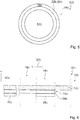
- Fig. 4 shows a cooktop 32b with a cooktop device 10b which has a temperature compensation unit 16b (cf. Fig. 4 and 5 ).
- the temperature compensation unit 16b significantly reduces a temperature gradient of a cooktop plate 12b between an installation area 14b and an area 18b surrounding the installation area 14b.
- the temperature compensation unit 16b In an assembled state, the temperature compensation unit 16b is essentially arranged in the surrounding area 18b.
- the temperature compensation unit 16b heats the hob plate 12b in the surrounding area 18b.
- the temperature compensation unit 16b has three heating elements 22b in the surrounding area 18b.
- the heating elements 22b essentially surround the installation area 14b in the assembled state. In the assembled state, the heating elements 22b are arranged concentrically around the installation area 14a.
- the heating element 22b is arranged in the surrounding area 18b.
- the temperature compensation unit 16b supplies the hob 12b in the surrounding area 18b with heat.
- the heating element 22b of the temperature compensation unit 16b heats the hob plate 12b in the surrounding area 18b.
- the temperature compensation unit 16b In an installed position, the temperature compensation unit 16b is largely arranged in a vertical direction 40b below the hob plate 12b. In the assembled state, the temperature compensation unit 16b is arranged on a surface of the hob plate 12b. In the assembled state, the temperature compensation unit 16b is designed as a coating on the hob plate 12b.
- the temperature compensation unit 16b has three temperature compensation elements 26b in the present exemplary embodiment. With regard to a plane oriented parallel to a main extension plane of the hob plate 12b, the temperature compensation elements 26b essentially surround the installation area 14b in the assembled state. The temperature compensation elements 26b are arranged concentrically around the installation area 14b in the assembled state.
- the temperature compensation element 26b and the heating element 22b are formed in one piece.
- the temperature compensation element 26b is designed as an electrical conductor.
- the temperature compensation element 26b has a specific electrical conductivity of essentially 60 * 10 6 S / m at 0 ° C.
- the cooktop device 10b has an energy source 30b.
- the energy source 30b and the temperature compensation element 26b are electrically conductively connected to one another in the assembled state.
- the energy source 30b supplies the temperature compensation element 26b with electrical current.
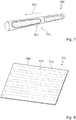
- Fig. 6 shows a cooktop 32c with a cooktop device 10c which has a temperature compensation unit 16c (cf. Fig. 6 and 7 ).
- the temperature compensation unit 16c significantly reduces a temperature gradient of a cooktop plate 12c between an installation area 14c and an area 18c surrounding the installation area 14c.
- the temperature compensation unit 16c is partially arranged in the installation area 14c.
- the temperature compensation unit 16c dissipates heat from the installation area 14c.
- the temperature compensation unit 16c extracts heat from the hob plate 12c.
- the temperature compensation unit 16c removes the heat extracted from the hob plate 12c in the installation area 14c from the installation area 14c.
- the temperature compensation unit 16c has a heat pipe 24c.
- the heat pipe 24c removes the heat extracted from the hob plate 12c in the installation area 14c from the installation area 14c. In an installed position, the temperature compensation unit 16c is largely arranged in a vertical direction 40c below the hob plate 12c.
- the heat pipe 24c and the cooktop plate 12c are arranged in thermal contact with one another.
- a first end of the heat pipe 24c and the hob plate 12c are arranged in thermal contact with one another in the installation area 14c.
- the heat pipe 24c receives heat from the cooktop 12c in the installation area 14c.
- the heat pipe 24c transports the heat absorbed by the hob plate 12c in the installation area 14c in a horizontal direction 20c out of the installation area 14c.
- the cooktop device 10c has a cooling unit 42c.
- the cooling unit 42c In an assembled state, the cooling unit 42c is arranged outside the installation area 14c.
- the heat pipe 24c and the cooling unit 42c are arranged in thermal contact with each other.
- the cooling unit 42c is arranged on a second end of the heat pipe 24c opposite the first end of the heat pipe 24c in the horizontal direction 20c.
- the second end of the heat pipe 24c and the cooling unit 42c are arranged in thermal contact with each other.
- the heat pipe 24c transports heat from the first end of the heat pipe 24c to the second end of the heat pipe 24c. At the second end of the heat pipe 24c, the heat pipe 24c releases heat to the cooling unit 42c.
- the cooktop device 10c could have at least one guide unit 44c (cf. Fig. 8 and 9 ).
- the guide unit 44c could have at least one guide channel 46c, which could be provided in particular for guiding at least one fluid.
- the guide unit 44c could in particular have a function of a heat pipe.
- the guide unit 44c could in particular be arranged in a meandering shape.
- the guide unit 44c could extend over a large part of a surface extension of the hob plate in a plane aligned parallel to a main plane of extension of the hob plate.
- the guide unit 44c could in particular be formed in one piece with the cooktop plate 12c (cf. Fig. 8 ).
- the guide unit 44c could in particular be arranged at least in large part within the hob plate 12c and in particular be formed by the hob plate 12c.
- the hob plate 12c could have at least one recess, which in particular could form a boundary of the guide channel 46c.
- the guide unit 44c could in particular be formed separately from the hob plate 12c and in particular attached to the hob plate 12c (cf. Fig. 9 ).
- the guide unit 44c could in particular have at least one guide element 48c, which in particular can be designed as a tube and could advantageously form a guide channel 46c.
- the guide unit 44c could in particular be fastened to an underside of the hob plate 12c.
- the hob plate 12c could, for example, have a groove which, in the installed position, could be arranged in particular on the underside of the hob plate 12c and could in particular be provided to accommodate the guide element 46c.
Landscapes
- Physics & Mathematics (AREA)
- Electromagnetism (AREA)
- Baking, Grill, Roasting (AREA)
- Electric Stoves And Ranges (AREA)
- Cookers (AREA)
Claims (13)
- Dispositif de table de cuisson comprenant au moins une plaque de cuisson (12a - c) qui est ménagée pour une pose au moins d'un récipient de cuisson dans au moins une zone de pose (14a - c) pour un échauffement, et comprenant au moins une unité de compensation de température (16a - c) qui est ménagée pour essentiellement réduire au moins un gradient de température de la plaque de cuisson (12a - c) entre la zone de pose (14a - c) et au moins une zone (18a - c) environnant la zone de pose (14a - c), caractérisé en ce que l'unité de compensation de température (16a - b) est ménagée pour échauffer la plaque de cuisson (12a - b) dans la zone (18a - b) environnante.
- Dispositif de table de cuisson selon la revendication 1, caractérisé en ce que l'unité de compensation de température (16a - c) est ménagée pour régler le gradient de température de la plaque de cuisson (12a - c) sur maximum 100 K/mm entre la zone de pose (14a - c) et la zone (18a - c) environnante dans une direction horizontale (20a - c) orientée parallèlement à un plan d'étendue principale de la plaque de cuisson (12a - c).
- Dispositif de table de cuisson selon la revendication 1, caractérisé en ce que l'unité de compensation de température (16b) présente dans la zone environnante (18b) au moins un élément chauffant (22b) qui est ménagé pour échauffer la plaque de cuisson (12b) dans la zone (18b) environnante.
- Dispositif de table de cuisson selon l'une quelconque des revendications précédentes, caractérisé en ce que l'unité de compensation de température (16a ; 16c) est ménagée pour évacuer la chaleur hors de la zone de pose (14a ; 14c).
- Dispositif de table de cuisson selon la revendication 4, caractérisé en ce que l'unité de compensation de température (16c) présente au moins un tube thermique (24c) qui est ménagé pour évacuer la chaleur hors de la zone de pose (14c).
- Dispositif de table de cuisson selon l'une quelconque des revendications précédentes, caractérisé en ce que l'unité de compensation de température (16b - c), dans une position de montage, est disposée au moins en grande partie en dessous de la plaque de cuisson (12b - c).
- Dispositif de table de cuisson selon l'une quelconque des revendications précédentes, caractérisé en ce que l'unité de compensation de température (16a), dans une position de montage, est disposée au moins en grande partie au-dessus de la plaque de cuisson (12a).
- Dispositif de table de cuisson selon l'une quelconque des revendications précédentes, caractérisé en ce que l'unité de compensation de température (16a - b) présente au moins un élément de compensation de température (26a - b) qui entoure au moins essentiellement la zone de pose (14a - b) par rapport à un plan orienté parallèlement à un plan d'étendue principale de la plaque de cuisson (12a - b).
- Dispositif de table de cuisson selon la revendication 8, caractérisé en ce que l'unité de compensation de température (16a) présente au moins un élément supplémentaire de compensation de température (28a) lequel, dans au moins un état monté, relie entre eux l'élément de compensation de température (26a) et la zone de pose (14a).
- Dispositif de table de cuisson selon la revendication 8 ou 9, caractérisé en ce que l'élément de compensation de température (26a) présente une conductivité thermique spécifique d'au moins 10W/(m*K) à 0° C.
- Dispositif de table de cuisson selon l'une quelconque des revendications 8 à 10, caractérisé en ce que l'élément de compensation de température (26b) présente une conductivité électrique spécifique d'au moins 104 S/m à 0° C.
- Dispositif de table de cuisson selon la revendication 11, caractérisé par au moins une source d'énergie (30b) qui est ménagée pour alimenter l'élément de compensation de température (26b) en courant électrique.
- Table de cuisson, notamment table de cuisson à induction, comprenant au moins un dispositif de table de cuisson (10a - c) selon l'une quelconque des revendications précédentes.
Applications Claiming Priority (1)
| Application Number | Priority Date | Filing Date | Title |
|---|---|---|---|
| ES201630334A ES2633612B1 (es) | 2016-03-21 | 2016-03-21 | Dispositivo de campo de cocción |
Publications (2)
| Publication Number | Publication Date |
|---|---|
| EP3223586A1 EP3223586A1 (fr) | 2017-09-27 |
| EP3223586B1 true EP3223586B1 (fr) | 2020-07-29 |
Family
ID=58158973
Family Applications (1)
| Application Number | Title | Priority Date | Filing Date |
|---|---|---|---|
| EP17157799.2A Active EP3223586B1 (fr) | 2016-03-21 | 2017-02-24 | Plaque de cuisson |
Country Status (2)
| Country | Link |
|---|---|
| EP (1) | EP3223586B1 (fr) |
| ES (2) | ES2633612B1 (fr) |
Cited By (1)
| Publication number | Priority date | Publication date | Assignee | Title |
|---|---|---|---|---|
| EP4198400A1 (fr) * | 2021-12-17 | 2023-06-21 | BSH Hausgeräte GmbH | Dispositif d'appareil ménager, appareil ménager et procédé de fonctionnement d'un dispositif d'appareil ménager |
Families Citing this family (3)
| Publication number | Priority date | Publication date | Assignee | Title |
|---|---|---|---|---|
| ES2704877A1 (es) * | 2017-09-20 | 2019-03-20 | Bsh Electrodomesticos Espana Sa | Sistema de cocción |
| US20240035672A1 (en) * | 2020-12-11 | 2024-02-01 | BSH Hausgeräte GmbH | Cooking system and method for installing a cooking system |
| EP4260658A1 (fr) * | 2020-12-11 | 2023-10-18 | BSH Hausgeräte GmbH | Système de cuisson et procédé d'installation d'un système de cuisson |
Family Cites Families (7)
| Publication number | Priority date | Publication date | Assignee | Title |
|---|---|---|---|---|
| DE3602666A1 (de) * | 1986-01-29 | 1987-07-30 | Wmf Wuerttemberg Metallwaren | Einrichtung zum kochen von speisen |
| US5239916A (en) * | 1993-02-26 | 1993-08-31 | Lungchiang Hu | Watercool electromagnetic induction heating wok |
| EP0621739B1 (fr) * | 1993-04-21 | 1999-11-03 | Wolfgang Dr. Herchenbach | Système de cuisson |
| US6884975B2 (en) * | 2002-11-12 | 2005-04-26 | The Boeing Company | Localized stress relief by induction heating |
| JP2008166088A (ja) * | 2006-12-28 | 2008-07-17 | Nippon Foil Mfg Co Ltd | 電磁誘導加熱コンロ用マット |
| JP5671470B2 (ja) * | 2009-10-23 | 2015-02-18 | パナソニックIpマネジメント株式会社 | 誘導加熱装置 |
| JP2013161767A (ja) * | 2012-02-09 | 2013-08-19 | Kansai Electric Power Co Inc:The | Ih式加熱調理器 |
-
2016
- 2016-03-21 ES ES201630334A patent/ES2633612B1/es not_active Revoked
-
2017
- 2017-02-24 ES ES17157799T patent/ES2814340T3/es active Active
- 2017-02-24 EP EP17157799.2A patent/EP3223586B1/fr active Active
Non-Patent Citations (1)
| Title |
|---|
| None * |
Cited By (1)
| Publication number | Priority date | Publication date | Assignee | Title |
|---|---|---|---|---|
| EP4198400A1 (fr) * | 2021-12-17 | 2023-06-21 | BSH Hausgeräte GmbH | Dispositif d'appareil ménager, appareil ménager et procédé de fonctionnement d'un dispositif d'appareil ménager |
Also Published As
| Publication number | Publication date |
|---|---|
| ES2633612B1 (es) | 2018-07-04 |
| ES2633612A1 (es) | 2017-09-22 |
| ES2814340T3 (es) | 2021-03-26 |
| EP3223586A1 (fr) | 2017-09-27 |
Similar Documents
| Publication | Publication Date | Title |
|---|---|---|
| EP3223586B1 (fr) | Plaque de cuisson | |
| DE69512605T2 (de) | Induktions-Kochmulde | |
| EP2975289B1 (fr) | Plaque de cuisson | |
| DE3102919A1 (de) | Strahlungsheizer fuer herde mit ebenen kochplatten | |
| DE102013218714A1 (de) | Kochfeldvorrichtung | |
| EP2838316A2 (fr) | Unité de chauffage à induction | |
| DE102007037881A1 (de) | Induktorvorrichtung | |
| CH658761A5 (de) | Elektrische heizvorrichtung fuer kochherde mit einer kochplatte aus glaskeramik. | |
| EP1448024B1 (fr) | Equipement du chauffage avec deux domaines | |
| DE102019210368B4 (de) | Elektrische Stromdurchführung | |
| WO2018116062A1 (fr) | Dispositif pour appareil de cuisson et procédé de montage d'un dispositif pour appareil de cuisson | |
| DE102013107089B4 (de) | Induktionskochfeld | |
| DE102008020150B4 (de) | Kocheinheitsvorrichtung | |
| DE102012219264A1 (de) | Hausgerätevorrichtung | |
| EP3297506B1 (fr) | Système de cuisson | |
| EP1601236A2 (fr) | Dispositif de cuisson comprenant une unité de refroidissement | |
| EP3685632A1 (fr) | Système de cuisson | |
| DE112006000993T5 (de) | Verteilungsleiter | |
| EP3679304B2 (fr) | Dispositif de plaque de cuisson | |
| DE102012217058A1 (de) | Thermogeneratoreinrichtung und Gasbrenner mit einer solchen Thermogeneratoreinrichtung | |
| EP3030044A1 (fr) | Plaque de cuisson | |
| DE102018219969A1 (de) | Kochfeldvorrichtung | |
| EP4098082B1 (fr) | Dispositif de cuisson à induction | |
| EP3664579B1 (fr) | Dispositif formant appareil de cuisson à induction | |
| EP1840472B1 (fr) | Plaque de cuisson au gaz |
Legal Events
| Date | Code | Title | Description |
|---|---|---|---|
| PUAI | Public reference made under article 153(3) epc to a published international application that has entered the european phase |
Free format text: ORIGINAL CODE: 0009012 |
|
| STAA | Information on the status of an ep patent application or granted ep patent |
Free format text: STATUS: THE APPLICATION HAS BEEN PUBLISHED |
|
| AK | Designated contracting states |
Kind code of ref document: A1 Designated state(s): AL AT BE BG CH CY CZ DE DK EE ES FI FR GB GR HR HU IE IS IT LI LT LU LV MC MK MT NL NO PL PT RO RS SE SI SK SM TR |
|
| AX | Request for extension of the european patent |
Extension state: BA ME |
|
| STAA | Information on the status of an ep patent application or granted ep patent |
Free format text: STATUS: REQUEST FOR EXAMINATION WAS MADE |
|
| 17P | Request for examination filed |
Effective date: 20180327 |
|
| RBV | Designated contracting states (corrected) |
Designated state(s): AL AT BE BG CH CY CZ DE DK EE ES FI FR GB GR HR HU IE IS IT LI LT LU LV MC MK MT NL NO PL PT RO RS SE SI SK SM TR |
|
| GRAP | Despatch of communication of intention to grant a patent |
Free format text: ORIGINAL CODE: EPIDOSNIGR1 |
|
| STAA | Information on the status of an ep patent application or granted ep patent |
Free format text: STATUS: GRANT OF PATENT IS INTENDED |
|
| INTG | Intention to grant announced |
Effective date: 20200320 |
|
| GRAS | Grant fee paid |
Free format text: ORIGINAL CODE: EPIDOSNIGR3 |
|
| GRAA | (expected) grant |
Free format text: ORIGINAL CODE: 0009210 |
|
| STAA | Information on the status of an ep patent application or granted ep patent |
Free format text: STATUS: THE PATENT HAS BEEN GRANTED |
|
| AK | Designated contracting states |
Kind code of ref document: B1 Designated state(s): AL AT BE BG CH CY CZ DE DK EE ES FI FR GB GR HR HU IE IS IT LI LT LU LV MC MK MT NL NO PL PT RO RS SE SI SK SM TR |
|
| REG | Reference to a national code |
Ref country code: CH Ref legal event code: EP |
|
| REG | Reference to a national code |
Ref country code: AT Ref legal event code: REF Ref document number: 1297349 Country of ref document: AT Kind code of ref document: T Effective date: 20200815 |
|
| REG | Reference to a national code |
Ref country code: IE Ref legal event code: FG4D Free format text: LANGUAGE OF EP DOCUMENT: GERMAN |
|
| REG | Reference to a national code |
Ref country code: DE Ref legal event code: R096 Ref document number: 502017006380 Country of ref document: DE |
|
| REG | Reference to a national code |
Ref country code: NL Ref legal event code: FP |
|
| REG | Reference to a national code |
Ref country code: LT Ref legal event code: MG4D |
|
| PG25 | Lapsed in a contracting state [announced via postgrant information from national office to epo] |
Ref country code: FI Free format text: LAPSE BECAUSE OF FAILURE TO SUBMIT A TRANSLATION OF THE DESCRIPTION OR TO PAY THE FEE WITHIN THE PRESCRIBED TIME-LIMIT Effective date: 20200729 Ref country code: PT Free format text: LAPSE BECAUSE OF FAILURE TO SUBMIT A TRANSLATION OF THE DESCRIPTION OR TO PAY THE FEE WITHIN THE PRESCRIBED TIME-LIMIT Effective date: 20201130 Ref country code: SE Free format text: LAPSE BECAUSE OF FAILURE TO SUBMIT A TRANSLATION OF THE DESCRIPTION OR TO PAY THE FEE WITHIN THE PRESCRIBED TIME-LIMIT Effective date: 20200729 Ref country code: NO Free format text: LAPSE BECAUSE OF FAILURE TO SUBMIT A TRANSLATION OF THE DESCRIPTION OR TO PAY THE FEE WITHIN THE PRESCRIBED TIME-LIMIT Effective date: 20201029 Ref country code: GR Free format text: LAPSE BECAUSE OF FAILURE TO SUBMIT A TRANSLATION OF THE DESCRIPTION OR TO PAY THE FEE WITHIN THE PRESCRIBED TIME-LIMIT Effective date: 20201030 Ref country code: LT Free format text: LAPSE BECAUSE OF FAILURE TO SUBMIT A TRANSLATION OF THE DESCRIPTION OR TO PAY THE FEE WITHIN THE PRESCRIBED TIME-LIMIT Effective date: 20200729 Ref country code: BG Free format text: LAPSE BECAUSE OF FAILURE TO SUBMIT A TRANSLATION OF THE DESCRIPTION OR TO PAY THE FEE WITHIN THE PRESCRIBED TIME-LIMIT Effective date: 20201029 Ref country code: HR Free format text: LAPSE BECAUSE OF FAILURE TO SUBMIT A TRANSLATION OF THE DESCRIPTION OR TO PAY THE FEE WITHIN THE PRESCRIBED TIME-LIMIT Effective date: 20200729 |
|
| PG25 | Lapsed in a contracting state [announced via postgrant information from national office to epo] |
Ref country code: IS Free format text: LAPSE BECAUSE OF FAILURE TO SUBMIT A TRANSLATION OF THE DESCRIPTION OR TO PAY THE FEE WITHIN THE PRESCRIBED TIME-LIMIT Effective date: 20201129 Ref country code: RS Free format text: LAPSE BECAUSE OF FAILURE TO SUBMIT A TRANSLATION OF THE DESCRIPTION OR TO PAY THE FEE WITHIN THE PRESCRIBED TIME-LIMIT Effective date: 20200729 Ref country code: LV Free format text: LAPSE BECAUSE OF FAILURE TO SUBMIT A TRANSLATION OF THE DESCRIPTION OR TO PAY THE FEE WITHIN THE PRESCRIBED TIME-LIMIT Effective date: 20200729 Ref country code: PL Free format text: LAPSE BECAUSE OF FAILURE TO SUBMIT A TRANSLATION OF THE DESCRIPTION OR TO PAY THE FEE WITHIN THE PRESCRIBED TIME-LIMIT Effective date: 20200729 |
|
| REG | Reference to a national code |
Ref country code: ES Ref legal event code: FG2A Ref document number: 2814340 Country of ref document: ES Kind code of ref document: T3 Effective date: 20210326 |
|
| PG25 | Lapsed in a contracting state [announced via postgrant information from national office to epo] |
Ref country code: RO Free format text: LAPSE BECAUSE OF FAILURE TO SUBMIT A TRANSLATION OF THE DESCRIPTION OR TO PAY THE FEE WITHIN THE PRESCRIBED TIME-LIMIT Effective date: 20200729 Ref country code: CZ Free format text: LAPSE BECAUSE OF FAILURE TO SUBMIT A TRANSLATION OF THE DESCRIPTION OR TO PAY THE FEE WITHIN THE PRESCRIBED TIME-LIMIT Effective date: 20200729 Ref country code: DK Free format text: LAPSE BECAUSE OF FAILURE TO SUBMIT A TRANSLATION OF THE DESCRIPTION OR TO PAY THE FEE WITHIN THE PRESCRIBED TIME-LIMIT Effective date: 20200729 Ref country code: SM Free format text: LAPSE BECAUSE OF FAILURE TO SUBMIT A TRANSLATION OF THE DESCRIPTION OR TO PAY THE FEE WITHIN THE PRESCRIBED TIME-LIMIT Effective date: 20200729 Ref country code: EE Free format text: LAPSE BECAUSE OF FAILURE TO SUBMIT A TRANSLATION OF THE DESCRIPTION OR TO PAY THE FEE WITHIN THE PRESCRIBED TIME-LIMIT Effective date: 20200729 Ref country code: IT Free format text: LAPSE BECAUSE OF FAILURE TO SUBMIT A TRANSLATION OF THE DESCRIPTION OR TO PAY THE FEE WITHIN THE PRESCRIBED TIME-LIMIT Effective date: 20200729 |
|
| REG | Reference to a national code |
Ref country code: DE Ref legal event code: R097 Ref document number: 502017006380 Country of ref document: DE |
|
| PG25 | Lapsed in a contracting state [announced via postgrant information from national office to epo] |
Ref country code: AL Free format text: LAPSE BECAUSE OF FAILURE TO SUBMIT A TRANSLATION OF THE DESCRIPTION OR TO PAY THE FEE WITHIN THE PRESCRIBED TIME-LIMIT Effective date: 20200729 |
|
| PLBE | No opposition filed within time limit |
Free format text: ORIGINAL CODE: 0009261 |
|
| STAA | Information on the status of an ep patent application or granted ep patent |
Free format text: STATUS: NO OPPOSITION FILED WITHIN TIME LIMIT |
|
| PG25 | Lapsed in a contracting state [announced via postgrant information from national office to epo] |
Ref country code: SK Free format text: LAPSE BECAUSE OF FAILURE TO SUBMIT A TRANSLATION OF THE DESCRIPTION OR TO PAY THE FEE WITHIN THE PRESCRIBED TIME-LIMIT Effective date: 20200729 |
|
| 26N | No opposition filed |
Effective date: 20210430 |
|
| PG25 | Lapsed in a contracting state [announced via postgrant information from national office to epo] |
Ref country code: SI Free format text: LAPSE BECAUSE OF FAILURE TO SUBMIT A TRANSLATION OF THE DESCRIPTION OR TO PAY THE FEE WITHIN THE PRESCRIBED TIME-LIMIT Effective date: 20200729 |
|
| PG25 | Lapsed in a contracting state [announced via postgrant information from national office to epo] |
Ref country code: MC Free format text: LAPSE BECAUSE OF FAILURE TO SUBMIT A TRANSLATION OF THE DESCRIPTION OR TO PAY THE FEE WITHIN THE PRESCRIBED TIME-LIMIT Effective date: 20200729 |
|
| REG | Reference to a national code |
Ref country code: BE Ref legal event code: MM Effective date: 20210228 |
|
| PG25 | Lapsed in a contracting state [announced via postgrant information from national office to epo] |
Ref country code: CH Free format text: LAPSE BECAUSE OF NON-PAYMENT OF DUE FEES Effective date: 20210228 Ref country code: LI Free format text: LAPSE BECAUSE OF NON-PAYMENT OF DUE FEES Effective date: 20210228 Ref country code: LU Free format text: LAPSE BECAUSE OF NON-PAYMENT OF DUE FEES Effective date: 20210224 |
|
| PG25 | Lapsed in a contracting state [announced via postgrant information from national office to epo] |
Ref country code: IE Free format text: LAPSE BECAUSE OF NON-PAYMENT OF DUE FEES Effective date: 20210224 |
|
| PG25 | Lapsed in a contracting state [announced via postgrant information from national office to epo] |
Ref country code: BE Free format text: LAPSE BECAUSE OF NON-PAYMENT OF DUE FEES Effective date: 20210228 |
|
| REG | Reference to a national code |
Ref country code: AT Ref legal event code: MM01 Ref document number: 1297349 Country of ref document: AT Kind code of ref document: T Effective date: 20220224 |
|
| PG25 | Lapsed in a contracting state [announced via postgrant information from national office to epo] |
Ref country code: AT Free format text: LAPSE BECAUSE OF NON-PAYMENT OF DUE FEES Effective date: 20220224 |
|
| PG25 | Lapsed in a contracting state [announced via postgrant information from national office to epo] |
Ref country code: HU Free format text: LAPSE BECAUSE OF FAILURE TO SUBMIT A TRANSLATION OF THE DESCRIPTION OR TO PAY THE FEE WITHIN THE PRESCRIBED TIME-LIMIT; INVALID AB INITIO Effective date: 20170224 |
|
| PG25 | Lapsed in a contracting state [announced via postgrant information from national office to epo] |
Ref country code: CY Free format text: LAPSE BECAUSE OF FAILURE TO SUBMIT A TRANSLATION OF THE DESCRIPTION OR TO PAY THE FEE WITHIN THE PRESCRIBED TIME-LIMIT Effective date: 20200729 |
|
| PG25 | Lapsed in a contracting state [announced via postgrant information from national office to epo] |
Ref country code: MK Free format text: LAPSE BECAUSE OF FAILURE TO SUBMIT A TRANSLATION OF THE DESCRIPTION OR TO PAY THE FEE WITHIN THE PRESCRIBED TIME-LIMIT Effective date: 20200729 |
|
| PG25 | Lapsed in a contracting state [announced via postgrant information from national office to epo] |
Ref country code: MT Free format text: LAPSE BECAUSE OF FAILURE TO SUBMIT A TRANSLATION OF THE DESCRIPTION OR TO PAY THE FEE WITHIN THE PRESCRIBED TIME-LIMIT Effective date: 20200729 |
|
| PG25 | Lapsed in a contracting state [announced via postgrant information from national office to epo] |
Ref country code: TR Free format text: LAPSE BECAUSE OF FAILURE TO SUBMIT A TRANSLATION OF THE DESCRIPTION OR TO PAY THE FEE WITHIN THE PRESCRIBED TIME-LIMIT Effective date: 20200729 |
|
| PGFP | Annual fee paid to national office [announced via postgrant information from national office to epo] |
Ref country code: NL Payment date: 20260218 Year of fee payment: 10 |
|
| PGFP | Annual fee paid to national office [announced via postgrant information from national office to epo] |
Ref country code: GB Payment date: 20260219 Year of fee payment: 10 |
|
| PGFP | Annual fee paid to national office [announced via postgrant information from national office to epo] |
Ref country code: ES Payment date: 20260319 Year of fee payment: 10 |
|
| PGFP | Annual fee paid to national office [announced via postgrant information from national office to epo] |
Ref country code: DE Payment date: 20260228 Year of fee payment: 10 |
|
| PGFP | Annual fee paid to national office [announced via postgrant information from national office to epo] |
Ref country code: FR Payment date: 20260219 Year of fee payment: 10 |