EP4198400A1 - Dispositif d'appareil ménager, appareil ménager et procédé de fonctionnement d'un dispositif d'appareil ménager - Google Patents
Dispositif d'appareil ménager, appareil ménager et procédé de fonctionnement d'un dispositif d'appareil ménager Download PDFInfo
- Publication number
- EP4198400A1 EP4198400A1 EP22208911.2A EP22208911A EP4198400A1 EP 4198400 A1 EP4198400 A1 EP 4198400A1 EP 22208911 A EP22208911 A EP 22208911A EP 4198400 A1 EP4198400 A1 EP 4198400A1
- Authority
- EP
- European Patent Office
- Prior art keywords
- unit
- mounting plate
- household appliance
- appliance device
- recess
- Prior art date
- Legal status (The legal status is an assumption and is not a legal conclusion. Google has not performed a legal analysis and makes no representation as to the accuracy of the status listed.)
- Pending
Links
Images

Classifications
-
- F—MECHANICAL ENGINEERING; LIGHTING; HEATING; WEAPONS; BLASTING
- F24—HEATING; RANGES; VENTILATING
- F24C—DOMESTIC STOVES OR RANGES ; DETAILS OF DOMESTIC STOVES OR RANGES, OF GENERAL APPLICATION
- F24C15/00—Details
- F24C15/10—Tops, e.g. hot plates; Rings
- F24C15/102—Tops, e.g. hot plates; Rings electrically heated
-
- H—ELECTRICITY
- H05—ELECTRIC TECHNIQUES NOT OTHERWISE PROVIDED FOR
- H05B—ELECTRIC HEATING; ELECTRIC LIGHT SOURCES NOT OTHERWISE PROVIDED FOR; CIRCUIT ARRANGEMENTS FOR ELECTRIC LIGHT SOURCES, IN GENERAL
- H05B6/00—Heating by electric, magnetic or electromagnetic fields
- H05B6/02—Induction heating
- H05B6/06—Control, e.g. of temperature, of power
- H05B6/062—Control, e.g. of temperature, of power for cooking plates or the like
-
- H—ELECTRICITY
- H05—ELECTRIC TECHNIQUES NOT OTHERWISE PROVIDED FOR
- H05B—ELECTRIC HEATING; ELECTRIC LIGHT SOURCES NOT OTHERWISE PROVIDED FOR; CIRCUIT ARRANGEMENTS FOR ELECTRIC LIGHT SOURCES, IN GENERAL
- H05B6/00—Heating by electric, magnetic or electromagnetic fields
- H05B6/02—Induction heating
- H05B6/10—Induction heating apparatus, other than furnaces, for specific applications
- H05B6/12—Cooking devices
- H05B6/1209—Cooking devices induction cooking plates or the like and devices to be used in combination with them
- H05B6/1218—Cooking devices induction cooking plates or the like and devices to be used in combination with them with arrangements using lights for heating zone state indication
-
- H—ELECTRICITY
- H05—ELECTRIC TECHNIQUES NOT OTHERWISE PROVIDED FOR
- H05B—ELECTRIC HEATING; ELECTRIC LIGHT SOURCES NOT OTHERWISE PROVIDED FOR; CIRCUIT ARRANGEMENTS FOR ELECTRIC LIGHT SOURCES, IN GENERAL
- H05B2206/00—Aspects relating to heating by electric, magnetic, or electromagnetic fields covered by group H05B6/00
- H05B2206/02—Induction heating
- H05B2206/022—Special supports for the induction coils
-
- H—ELECTRICITY
- H05—ELECTRIC TECHNIQUES NOT OTHERWISE PROVIDED FOR
- H05B—ELECTRIC HEATING; ELECTRIC LIGHT SOURCES NOT OTHERWISE PROVIDED FOR; CIRCUIT ARRANGEMENTS FOR ELECTRIC LIGHT SOURCES, IN GENERAL
- H05B2213/00—Aspects relating both to resistive heating and to induction heating, covered by H05B3/00 and H05B6/00
- H05B2213/04—Heating plates with overheat protection means
Definitions
- the invention relates to a household appliance device according to claim 1, a household appliance according to claim 12 and a method for operating a household appliance device according to claim 13.
- a hob device is already known from the prior art, which has a mounting plate and a heating device.
- During a cooking process there can be high thermal stresses in the worktop and thus damage to the worktop, such as breaking, and endangering an operator, precisely when the stresses in the worktop are greater than a breaking strength of a Material of the mounting plate.
- This can occur above all when a temperature difference between a temperature on an upper side of the installation plate and a temperature on an underside of the installation plate is too large.
- the upper side of the mounting plate heats up with inductive heating of a mounting unit on the mounting plate.
- the underside of the installation plate usually retains its almost initial temperature, which can correspond to room temperature, for example.
- the mounting plate can be damaged.
- the process described can occur primarily in an area of at least one recess of the mounting plate. Due to the recess in the mounting plate, thermal stresses can occur in the mounting plate that are up to three times higher than in a mounting plate without a recess when it is heated.
- the object of the invention consists in particular in providing a generic device with improved properties with regard to safety, in particular operator safety.
- the object is achieved by the features of the Claims 1, 12 and 13 solved, while advantageous embodiments and developments of the invention can be found in the dependent claims.
- the invention relates to a household appliance device, in particular a cooktop device, with at least one compensation unit arranged on the underside of a mounting plate, in particular a kitchen worktop, which is provided to reduce thermal stresses in the mounting plate.
- a configuration of this type can increase safety with regard to operator safety, specifically in particular with regard to operating a household appliance device and/or a household appliance. Furthermore, thermal stresses in a pedestal can be reduced and damage, in particular breaking, of the pedestal, in particular a surface of the pedestal, and possible damage to other objects, such as a heating unit, can be prevented. A particularly high level of safety for an operator can thus be ensured, so that in at least one operating state it is possible to safely carry out heating of at least one installation unit. Furthermore, ease of use can be increased. Furthermore, due to a compensation unit, a temperature difference between a temperature on an upper side of the installation plate and an underside of the installation plate can be reduced.
- a compact and simple construction can be provided by means of the mounting plate, so that in turn an efficiency in terms of manufacturing and/or cost and/or assembly and/or disassembly and/or product and/or work efficiency can be increased. Production and/or material costs can advantageously be reduced.
- alternative mounting plates can be used, which are preferably designed differently from a hob plate, for example a glass ceramic plate.
- the domestic appliance device could be, for example, a cooking device device, possibly a microwave device and/or a grill device and/or a steam device device and/or an oven device and/or preferably the hob device.
- the household appliance device forms a subassembly of a household appliance, in particular a cooking appliance, such as, for example a microwave and/or a grill and/or a steamer and/or an oven and/or preferably a hob.
- the hob device could be designed as a resistance hob device and/or preferably as an induction hob device.
- the hob device designed as an induction hob device is advantageously a subassembly of an induction hob.
- a “cooktop device” should be understood to mean at least a part, in particular a subassembly, of at least one cooktop, advantageously the induction cooktop, whereby in particular accessory units for the cooktop can also be included, such as a sensor unit for measuring a temperature of a set-up unit, in particular one Cooking utensil, and / or a cooking item, and / or a detection unit for detecting at least the installation unit. It would also be conceivable for the household appliance device to include the entire household appliance, in particular the entire hob.
- the household appliance device and/or the household appliance is/are intended for use and/or arrangement in a household, in particular a kitchen.
- the household appliance could in turn be part of a household appliance system, in particular a cooktop system, in which case the household appliance system could have a large number of units and/or devices which can be used to treat and/or process food.
- the household appliance system could be in the form of a hob system, in particular an induction hob system, and preferably additionally have at least one household appliance object, in particular a hob object.
- the household appliance object could be at least the installation unit and/or an extraction unit and/or at least the sensor unit and/or at least one additional sensor unit, in particular at least one temperature sensor, for placement in the cookware and/or in the food to be cooked, for example in the form of of a spit, act. It would also be conceivable for the household appliance object to be at least partially part of a subgroup of at least the household appliance, in particular the hob.
- the household appliance object could, for example, have at least one control unit, for example a remote control, and/or at least one operator interface and/or at least one extractor fan unit and/or at least one heating unit control electronics.
- the mounting plate is at least one unit, in particular a plate-like unit, which is provided for setting up at least the mounting unit and/or for placing at least one food item, in particular the item to be cooked.
- the mounting plate could be designed, for example, as a worktop, in particular as a kitchen worktop, or as a partial area of at least one worktop, in particular at least one kitchen worktop, in particular of the household appliance system.
- the kitchen worktop in particular in contrast to a hob top, is additionally provided to provide a food preparation area, in particular in which, for example, food could be cut and/or mixed and/or pounded and/or peeled.
- the kitchen worktop is a piece of furniture, preferably a piece of kitchen furniture.
- the kitchen worktop is advantageously part of the kitchen and in particular delimits and/or closes part of an assembly of kitchen cabinets and/or kitchen furniture and/or other household appliances, such as a dishwasher and/or a washing machine and/or an oven, at the top .
- the mounting plate could be designed as a hob plate.
- the mounting plate designed as a hob plate could form at least part of an outer hob housing of the hob and advantageously together with at least one housing unit of the hob, to which the hob plate is connected in at least one assembled state, could form at least a large part of the outer hob housing.
- the mounting plate is preferably made of a non-metallic material.
- the installation plate could be at least partially or at least for the most part made of glass and/or glass ceramic and/or Neolith and/or Dekton and/or wood and/or marble and/or stone, in particular natural stone, and/or be made of laminate and/or plastic and/or ceramic and/or a composite material.
- the expression "for the most part” should be understood to mean at least 55%, advantageously at least 65%, preferably at least 75%, particularly preferably at least 85% and particularly advantageously at most 95% of a volume and/or mass fraction.
- the mounting plate has a thickness, in particular a material thickness, of in particular at most 30 mm, preferably at most 20 mm and particularly preferably at most 12 mm.
- location designations refer to such as “below” or "above” to the assembled state of the installation plate, unless this is explicitly described otherwise.
- the set-up unit can have a small household appliance and/or the cookware.
- the small household appliance could be a coffee maker and/or a toaster and/or a kettle and/or a blender and/or a stirrer, for example.
- the small household appliance could be supplied with energy at least partially inductively when it is placed on the mounting plate.
- the cooking utensil can be designed, for example, as a pot and/or pan and/or roaster. If the domestic appliance device is designed as an induction hob device, the cooking utensil could be at least partially inductively supplied with energy when it is placed on the kitchen worktop, at least for heating.
- the set-up unit can include a base unit which is provided as a base under the cookware and/or the small household appliance.
- the support unit can advantageously be arranged between the support plate and the cooking utensil and/or the small household appliance.
- the installation unit can be arranged in a cooking surface area on the installation plate.
- the installation plate has engravings and/or imprints for marking a cooking surface area, in particular the cooking surface area mentioned, for at least the installation unit.
- the mounting plate is preferably free of engravings and/or imprints.
- the domestic appliance device, in particular the mounting plate has at least the cooking surface area.
- the cooking surface area is preferably designed as a variable cooking surface area.
- a “variable cooking surface area” is to be understood as meaning a cooking surface area that is intended to form at least one heating zone that is adapted to at least the installed installation unit, in particular the small household appliance and/or the cooking utensil.
- the heating zone can preferably be adapted to the set-up unit with regard to at least one size and/or shape.
- the variable cooking surface area differs from a cooking surface area in which the heating zones are fixed, in particular by markings on the mounting plate.
- the domestic appliance device preferably has at least one heating unit, which could be embodied as a resistance heating unit and/or preferably as an induction heating unit.
- the heating unit is arranged below the mounting plate.
- the heating unit for heating at least the set-up unit is provided in the cooking surface area on the set-up plate.
- the heating unit is designed as an induction heating unit
- at least one part of the mounting plate namely at least one top side of the mounting plate, can heat up in at least the cooking surface area when the installation unit is heated in at least one operating state.
- the compensation unit is arranged on the underside of the mounting plate.
- the compensation unit can at least partially reduce thermal stresses in the mounting plate.
- Thermal stresses are to be understood here and in the following as thermally induced mechanical stresses in the mounting plate, which are caused due to at least one temperature change and/or due to at least one temperature gradient, in particular of the mounting plate, in connection with a thermal expansion coefficient, in particular of the mounting plate can.
- the thermally induced mechanical stresses arise without an external influence of force, namely without an external force acting on the mounting plate.
- higher thermal stresses of the mounting plate occur in an area above and/or around the heating unit, in particular in the cooking surface area, preferably the heating zone, for heating the mounting unit.
- the manner in which the thermal stresses act and/or occur in the mounting plate can depend, in particular at least in the operating state, on a temperature distribution in the cooking surface area and in the mounting plate.
- Provided here and in the following is to be understood to mean specially programmed, designed and/or equipped.
- the fact that an object is provided for a specific function should be understood to mean that the object fulfills and/or executes this specific function in at least one application and/or operating state.
- the domestic appliance device has a mounting plate, in particular the aforementioned mounting plate, which has at least one cutout, in particular for instrumentation.
- a mounting plate in particular the aforementioned mounting plate, which has at least one cutout, in particular for instrumentation.
- This can be a comfort, and although operator comfort is improved and safety is further increased.
- At least one function of a domestic appliance device can be provided for the operator by means of a recess, such as temperature detection and/or an illumination display of at least one cooking surface area and/or a heating zone. This in turn can increase efficiency.
- the recess of the mounting plate preferably extends at least partially along a normal direction from the top to the bottom of the mounting plate and can be created by a suitable shaping process either directly during production of the mounting plate, for example by a suitable mold, or subsequently, for example by a drilling process or a milling process or the like, be introduced into the mounting plate.
- the cutout is preferably designed as a bore in the mounting plate.
- the recess could have a diameter of at least 1 mm, advantageously at least 5 mm, preferably at least 10 mm and particularly preferably at most 20 mm.
- the fact that the cutout is provided for instrumentation should be understood to mean that at least one function of the household appliance device can be made available to the operator by means of the cutout.
- the cutout is provided at least to enable, in particular, low-loss transmission of infrared radiation and/or visible light to and/or from another unit of the household appliance device, in particular a sensor unit and/or a lighting unit, from an area below the mounting plate to an area above to allow the mounting plate.
- the sensor unit could detect and/or measure at least one temperature of the set-up unit placed on the set-up plate through the recess.
- a cooking surface area, in particular the cooking surface area, and/or a heating zone for heating the set-up unit could be displayed for the operator by means of the lighting unit.
- the positioning unit could be provided for positioning above the cutout and/or next to the cutout.
- At least one radiation-guiding element of the household appliance device could be arranged in a mounted state in the recess, for example.
- a "radiation-guiding element” is to be understood as an element which is suitable for both infrared radiation, in particular infrared radiation with a wavelength range between 800 nm and 7,000 nm, and for visible light with a wavelength range between 380 nm and 800 nm and which is intended to transport visible light and/or infrared radiation at least partially along the normal direction of the installation plate, from the top to the bottom of the installation plate and/or from the bottom to the top of the installation plate .
- the radiation-guiding element is preferably formed at least to a large extent, particularly preferably entirely, from quartz.
- a "normal direction” of an object is to be understood as meaning a direction which runs perpendicularly to a main plane of extension of the object.
- a “main extension plane” of a structural unit is to be understood as a plane which is parallel to a largest side surface of an imaginary cuboid which just about completely encloses the structural unit and in particular runs through the center point of the cuboid. It would also be conceivable for the recess to be free of elements and/or units, in particular the radiation-guiding element.
- the compensating unit is arranged at least in sections around the recess. In this way, safety, namely operator safety, can be increased and improved comfort can be provided. In addition, thermal stresses in a mounting plate can be reduced, specifically in a region of a recess in the mounting plate. Furthermore, damage to the mounting plate can advantageously be prevented.
- the compensating unit can be arranged in an angular range, for example from 0° to at least 40°, advantageously at least 60°, preferably at least 90° and particularly preferably at least 150° around the recess. It would also be conceivable for the compensating unit to be arranged in an angular range of 0° to at least 170°, advantageously 230°, preferably 270° and particularly preferably at most 300° around the recess.
- the compensation unit In order to further increase safety and to reduce thermal stress in a mounting plate as best as possible, specifically in an area of a recess in the mounting plate, it is proposed that the compensation unit have an annular area which surrounds the recess.
- the compensation unit preferably completely surrounds the recess by means of the annular region.
- the ring-shaped area could be circular, oval, or angular in shape, such as square or rectangular. If the ring-shaped area has an angular shape, its edges could be rounded, for example.
- the ring-shaped area has an inner diameter which at least essentially corresponds to a diameter of the recess.
- a construction can be improved and thus safety, namely operator safety, can be further increased.
- a recess in a mounting plate can advantageously be surrounded by a compensation unit, so that thermal stresses in the mounting plate, specifically in the area of the recess, can be reduced. This in turn can prevent damage, for example breaking, to the mounting plate.
- the inside diameter of the ring-shaped area could, for example, be at least 5 mm, advantageously at least 10 mm and preferably at most 20 mm.
- “at least essentially” should be understood to mean that a deviation from a specified value is less than 25%, preferably less than 10% and particularly preferably less than 5% of the specified value.
- the inner diameter of the ring-shaped area preferably deviates by at most 8%, advantageously at most 3% and particularly preferably by at most 1% from the diameter of the recess.
- the domestic appliance device has an induction heating unit, the inner diameter of which is larger than an outer diameter of the ring-shaped area.
- the induction heating unit is the aforementioned induction heating unit.
- the induction heating unit is preferably designed as a matrix induction heating unit and is intended in particular to provide the variable cooking surface area.
- the induction heating unit has at least one induction heating element and preferably a multiplicity of induction heating elements.
- a "heating unit” is to be understood as a unit which is intended, at least in one operating state, to transmit at least a large part of electrical energy to the installation unit, preferably through at least the installation plate, and/or to convert electrical energy into heat in order in particular to to heat at least the set-up unit, preferably through at least the set-up plate.
- the heating unit is intended to generate a power of at least 100 W, in particular at least 500 W, advantageously at least 1000 W, preferably at least 2000 W to transmit.
- the induction heating unit preferably has at least one heating element designed as an inductor.
- An "inductor” is to be understood here as an element which has at least one induction coil and/or is designed as an induction coil and which is intended to supply energy, in particular in the form of an alternating magnetic field, to at least one receiving element in at least the operating state.
- the receiving element is designed in particular as a part and/or a subassembly of a receiving unit and is provided in particular for receiving the energy provided by at least one inductor.
- the receiving unit can be part of the household appliance device. Alternatively, it is conceivable that the receiving unit is designed as a unit that is independent of the household appliance device and/or as part of a further device that is independent of the household appliance device.
- the receiving unit can be provided for setting up in an area above the inductor and/or the additional inductor.
- the receiving unit is part of the set-up unit.
- the receiving unit could be part of the small household appliance and/or the cooking utensil and/or the base unit.
- the installation unit could have at least one secondary coil as a receiving element for receiving the energy provided by the inductor and/or the additional inductor.
- the receiving element could also be embodied as a metallic heating element, in particular as an at least partially ferromagnetic heating element, for example as a ferromagnetic base of the installation unit, in particular the cooking utensil and/or the base unit and/or the small household appliance, in which in the operating mode of the heating unit caused by the inductor eddy currents and / or magnetic reversal effects, which are converted into heat.
- a metallic heating element in particular as an at least partially ferromagnetic heating element, for example as a ferromagnetic base of the installation unit, in particular the cooking utensil and/or the base unit and/or the small household appliance, in which in the operating mode of the heating unit caused by the inductor eddy currents and / or magnetic reversal effects, which are converted into heat.
- the inner diameter of the induction heating unit is preferably an inner diameter of the induction coil.
- the induction coil can have at least one turn and advantageously a plurality of turns, specifically at least two turns.
- a first inner turn of the induction coil defines the inner diameter.
- the inside diameter of the induction heating unit can, for example, be at least 20 mm, advantageously at least 30 mm, preferably at least 45 mm and preferably be at most 60 mm and particularly preferably at most 80 mm.
- the inner diameter of the induction heating unit can be at least 1%, advantageously at least 3%, preferably at least 10% and particularly preferably at least 30% larger than the outer diameter of the annular region.
- the inside diameter of the induction heating unit can be at most 80%, advantageously at most 60% and preferably at most 50% larger than the outside diameter of the ring-shaped area.
- the outer diameter of the ring-shaped area can be, for example, at least 10 mm, advantageously at least 20 mm, preferably at least 25 mm and preferably at most 30 mm.
- the compensating unit prefferably be fixed on the underside of the mounting plate by means of a non-positive and/or positive connection, for example a screw connection and/or locking connection and/or plug connection and/or rotary connection.
- the compensating unit has a contact surface for the integral connection with the underside of the mounting plate.
- safety for example with regard to a secure fixing of a compensation unit on an underside of a mounting plate, can be optimized.
- safety with regard to operator safety can be further increased and advantageously damage to the mounting plate can be prevented.
- an efficiency in terms of manufacturing and/or cost and/or assembly and/or disassembly and/or product and/or work efficiency can be increased. Manufacturing and/or material costs and assembly and/or disassembly costs can advantageously be reduced.
- An integral connection can be understood to mean, for example, a welded connection and/or a connection due to an injection molding process and/or preferably an adhesive connection.
- the compensating unit can be welded and/or preferably glued to the underside of the mounting plate.
- the compensation unit could be at least partially coated with an adhesive on the contact surface.
- the adhesive is preferably a non-metallic substance intended to join at least two elements by surface adhesion and its internal strength.
- the compensation unit in at least one method step, in particular a gluing step, in the method for installing the household appliance device, the compensation unit can be glued to the underside of the mounting plate.
- the adhesive could be applied to the contact surface of the compensation unit become.
- the adhesive could be applied to the underside of the riser plate. In the installed state, the adhesive fixes the compensating unit in a contact-locking and/or material-locking manner with the underside of the mounting plate. It would also be conceivable for the household appliance device to have an adhesive in the form of double-sided adhesive tape, by means of which the compensation unit can be fixed on the underside of the mounting plate and, in particular, is fixed on the underside of the mounting plate, at least in the assembled state.
- the adhesive can have a material thickness of at least 0.1 mm, advantageously at most 0.3 mm, preferably at most 0.5 mm and particularly preferably at most 1 mm.
- the compensating unit has a heating element for local heating of the mounting plate.
- a compact construction can thus be provided.
- an area on an underside of a mounting plate can advantageously be heated in order to reduce thermal stresses in the mounting plate. This in turn can prevent damage to the mounting plate, such as the mounting plate breaking.
- the heating element could be designed as an induction heating element and, for example, have a coil or be designed as such.
- the heating element could, in particular, have a closed conductor loop.
- the compensating unit could be inductively heatable by means of the heating element.
- the heating element is particularly preferably designed as a resistance heating element.
- the compensating unit could be made at least partially and preferably at least to a large extent, for example, from a metal, for example aluminum and/or aluminum oxide and/or copper and/or gold, and/or a semimetal, for example silicon, and/or a mineral, for example mica and /or mica, and/or a composite material.
- the compensating unit uses the heating element to cover the underside of the support plate also heated. If the domestic appliance device has a control unit which switches on the heating element when a temperature limit value is exceeded, increased safety can be provided and comfort can be improved. In addition, efficiency can be increased since a compensating unit, namely a heating element, can only be operated and switched on when heating of an underside of a mounting plate is required to reduce thermal stresses.
- the heating element when the heating element is activated when a temperature limit value is exceeded, thermal stresses in the mounting plate can be reduced, specifically before the thermal stresses generated by high temperatures are greater than a breaking strength of the mounting plate.
- the temperature limit could for example be at least 150°C, advantageously at least 200°C, preferably at least 220°C and particularly preferably at most 300°C. If the upper side of the mounting plate has a temperature above the temperature limit value, the control unit can switch on the heating element for heating the underside of the mounting plate.
- the control unit could be a local control unit, for example located in the balancing unit and/or on the underside of the mounting plate.
- the control unit is preferably part of a household appliance control unit, in particular a cooktop control unit, of the household appliance device.
- the household appliance device can have several, specifically at least two, balancing units and the mounting plate can have several, specifically at least two, recesses.
- the compensation units could each be arranged on one of the recesses.
- the at least two compensation units could communicate with one another, for example by means of wireless and/or wired communication, such as OBUS. If the temperature limit is exceeded, the control unit could switch on at least the heating element of the first compensation unit and at the same time at least one further heating element of at least the second compensation unit.
- the compensating unit could have a thickness of at least 6 mm and advantageously at most 10 mm, for example. Furthermore, it is proposed that the compensating unit has a thickness of at most 5 mm, advantageously at most 4 mm and preferably at most 2 mm. A compact construction can thus be provided and safety can be further increased. In addition, the integrability of a compensation unit can be improved become.
- the thickness should preferably be understood to mean a material thickness of the compensating unit. Particularly preferably, the compensating unit has a smaller thickness than the material thickness of the mounting plate.
- the thickness of the compensating unit and the material thickness of the mounting plate can differ by at least 2%, advantageously by at least 5% and preferably by at least 10%.
- the material thickness of the mounting plate exceeds the thickness of the compensating unit s.
- the material thickness of the mounting plate is preferably greater than the thickness of the compensating unit.
- a shape and/or size and/or dimension of the compensating unit is dependent on at least the recess in the mounting plate and/or a material composition and/or material thickness of the mounting plate and/or a shape and/or size and/or dimension of the induction heating unit.
- the invention is based on a method for operating a household appliance device, in particular the aforementioned household appliance device, thermal stresses in a mounting plate being reduced by a compensation unit arranged on an underside of the mounting plate.
- a household appliance device in particular the aforementioned household appliance device
- thermal stresses in a mounting plate being reduced by a compensation unit arranged on an underside of the mounting plate.
- Such an operating method can increase safety with regard to operator safety.
- safe and user-friendly operation of a household appliance device and/or a household appliance can be provided.
- thermal stresses in a slab can be limited and/or reduced and/or controlled. This in turn can advantageously prevent damage to the mounting plate.
- the household appliance device and/or the household appliance and/or the method should not be limited to the application and embodiment described above.
- the household appliance device and/or the household appliance and/or the method for fulfilling a functionality described herein can have a number of individual elements, components, units and method steps that differs from the number specified herein.
- values lying within the stated limits should also be considered disclosed and can be used as desired.
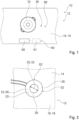
- the figure 1 shows a household appliance 10 designed as a hob with a household appliance device 12.
- the household appliance device 12 in the present case is accordingly designed as a hob device.
- the domestic appliance device 12 has a mounting plate 16 which is designed as a kitchen worktop 18 in this exemplary embodiment.
- the installation plate 16 could also be a hob plate, for example a glass ceramic plate.
- the domestic appliance device 12 has a cooking surface area 66 .
- the mounting plate 16 has the cooking surface area 66 .
- the erection plate 16 is provided at least for erecting at least one erection unit 70 .
- the installation unit 70 can be arranged in the cooking surface area 66 for at least one heating.
- the installation unit 70 is as in figure 1 shown, for example as cookware, designed as a pot. It would also be conceivable that the positioning unit 70 is alternatively and/or additionally a base unit and/or a small household appliance, such as a kettle and/or a coffee machine and/or a blender and/or a stirrer.
- the household appliance device 12 has an operator interface 68 which is integrated into the mounting plate 16 in the present example. At least the heating of the installation unit 70 can be controlled and/or regulated by an operator by means of the operator interface 68 .
- the mounting plate 16 has a recess 26 for an instrumentation.
- the recess 26 is arranged in the cooking surface area 66 and is provided at least to indicate to the operator a set-up position for the set-up unit 70 on the set-up plate 16 for at least the heating.
- a lighting unit of household appliance device 12 and/or a sensor unit of household appliance device 12 for example an IR sensor unit for measuring the temperature of installation unit 70, can be and/or is arranged in recess 26 and/or below recess 26.
- the positioning unit 70 is provided for positioning on the cutout 26 .
- the recess 26 forms a center point of the cooking surface area 66 .
- the household appliance device 12 has at least one compensation unit 20 for reducing thermal stresses in the mounting plate 16 .
- the compensating unit 20 is arranged on an underside 14 of the mounting plate (cf. figure 2 ).
- the compensating unit 20 is arranged around the recess 26 at least in sections. How figure 2 can be seen, the compensating unit 20 has an annular area 28 which surrounds the recess 26 .
- the annular region 28 has an inner diameter 30 which at least essentially corresponds to a diameter 32 of the recess 26 (cf. figure 2 ).
- the inner diameter 30 of the annular region 28 is 17 mm, for example.
- the compensating unit 20 has a contact surface 52 for the integral connection with the underside 14 of the mounting plate 16 .
- the compensating unit 20 could be welded to the underside 14 of the mounting plate 16, for example.
- the compensation unit 20 is glued to the underside 14 at the contact surface 52 .
- the compensating unit 20 has a thickness, namely a material thickness of at most 5 mm. In this exemplary embodiment, the thickness is 2 mm, for example.
- the compensating unit 20 is intended to prevent damage, for example breaking, to the mounting plate 16, which can be caused, for example, by a high temperature gradient in the mounting plate 16.
- an upper side 62 of the installation plate 16 heats up. If the installation plate 16 has an excessive temperature difference between the upper side 62 and the underside 14, namely excessive thermal stresses, the installation plate 16 can break , for example shatter.
- the compensating unit 20 is provided for heating at least the underside 14 of the mounting plate 16 .
- the compensating unit 20 has a heating element 53 for local heating of the mounting plate 16 .
- the heating element 53 is designed as a resistance heating element 56 .
- the household appliance device 12 has a control unit 60 which switches on the heating element 53 when a temperature limit value is exceeded.
- the temperature limit is approx. 220°C.
- the control unit 60 is part of a household appliance control unit 61, specifically a cooktop control unit (cf. figure 1 ).
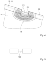
- FIG figure 4 Results of a thermal simulation of heating the underside 14 of the mounting plate 16 by means of the compensation unit 20, namely the heating element 53 are shown.
- the differently hatched areas represent areas in the mounting plate 16 with different temperatures.
- Heating with a power of 3W, for example has a temperature of approx.
- the temperature in a further area 76 can be approximately 100° C., for example.
- FIG 5 a process flow diagram of a process for operating the household appliance device 12 is shown schematically.
- the method of operation could include several method steps. In the present case, the method is only described using one method step 100 as an example.
- thermal stresses in the mounting plate 16 are reduced in method step 100 by the compensation unit 20 arranged on the underside 14 of the mounting plate 16 .
- the underside 14 of the mounting plate 16 is heated by means of the compensation unit 20 in method step 100 .
Landscapes
- Engineering & Computer Science (AREA)
- Physics & Mathematics (AREA)
- Electromagnetism (AREA)
- Chemical & Material Sciences (AREA)
- Combustion & Propulsion (AREA)
- Mechanical Engineering (AREA)
- General Engineering & Computer Science (AREA)
- Electric Stoves And Ranges (AREA)
Applications Claiming Priority (1)
| Application Number | Priority Date | Filing Date | Title |
|---|---|---|---|
| EP21383152 | 2021-12-17 |
Publications (1)
| Publication Number | Publication Date |
|---|---|
| EP4198400A1 true EP4198400A1 (fr) | 2023-06-21 |
Family
ID=78957245
Family Applications (1)
| Application Number | Title | Priority Date | Filing Date |
|---|---|---|---|
| EP22208911.2A Pending EP4198400A1 (fr) | 2021-12-17 | 2022-11-22 | Dispositif d'appareil ménager, appareil ménager et procédé de fonctionnement d'un dispositif d'appareil ménager |
Country Status (1)
| Country | Link |
|---|---|
| EP (1) | EP4198400A1 (fr) |
Citations (3)
| Publication number | Priority date | Publication date | Assignee | Title |
|---|---|---|---|---|
| WO2008110447A2 (fr) * | 2007-03-13 | 2008-09-18 | BSH Bosch und Siemens Hausgeräte GmbH | Table de cuisson dotée d'une zone de détection de température |
| WO2019058202A1 (fr) * | 2017-09-20 | 2019-03-28 | BSH Hausgeräte GmbH | Système de cuisson |
| EP3223586B1 (fr) * | 2016-03-21 | 2020-07-29 | BSH Hausgeräte GmbH | Plaque de cuisson |
-
2022
- 2022-11-22 EP EP22208911.2A patent/EP4198400A1/fr active Pending
Patent Citations (3)
| Publication number | Priority date | Publication date | Assignee | Title |
|---|---|---|---|---|
| WO2008110447A2 (fr) * | 2007-03-13 | 2008-09-18 | BSH Bosch und Siemens Hausgeräte GmbH | Table de cuisson dotée d'une zone de détection de température |
| EP3223586B1 (fr) * | 2016-03-21 | 2020-07-29 | BSH Hausgeräte GmbH | Plaque de cuisson |
| WO2019058202A1 (fr) * | 2017-09-20 | 2019-03-28 | BSH Hausgeräte GmbH | Système de cuisson |
Similar Documents
| Publication | Publication Date | Title |
|---|---|---|
| EP0637898B1 (fr) | Plan de travail et de cuisson | |
| DE19624648A1 (de) | Spezialtopf für eine Kochfeld-Garungseinheit | |
| EP4070695A1 (fr) | Ustensile de cuisine destiné à être posé sur une plaque de cuisson à induction, procédé de fonctionnement de l'ustensile de cuisine, procédé de fonctionnement de la coque intérieure de l'ustensile de cuisine et procédé de fonctionnement d'un système | |
| DE9308911U1 (de) | Kochgerät für einen Wok | |
| DE3117205A1 (de) | Optoelektronische kochfeldsteuerung | |
| EP4042909A1 (fr) | Ustensile de cuisine destiné à être posé sur une plaque de cuisson à induction | |
| EP3758562B1 (fr) | Système de cuisson | |
| DE202005016787U1 (de) | Vorrichtung zum Erwärmen von Speisen | |
| BE1029280B1 (de) | Küchenutensil zum Aufstellen auf ein Induktionskochfeld | |
| EP2983449B1 (fr) | Procede d'acceleration d'un processus de cuisson, dispositif de commande et appareil de cuisson correspondant | |
| EP4327628A1 (fr) | Système de transmission d'énergie par induction | |
| WO2018083565A1 (fr) | Fond de casserole | |
| WO2020128014A1 (fr) | Système de transfert d'énergie par induction | |
| EP4442079A2 (fr) | Dispositif de table de cuisson, système de table de cuisson, outil d'installation et procédé d'installation d'un dispositif de table de cuisson | |
| DE102005040041B3 (de) | Glaskeramikkochfeld mit wenigstens einem Kochfeldbereich | |
| EP4635257A1 (fr) | Système de plaque de cuisson, dispositif de plaque de cuisson et procédé d'installation d'un système de plaque de cuisson | |
| EP4701336A2 (fr) | Dispositif de plaque de cuisson, plaque de cuisson, procédé de fonctionnement d'un dispositif de plaque de cuisson | |
| DE102020205842A1 (de) | Gargeschirr | |
| DE102019207933A1 (de) | Küchensystem und Verfahren zu einem Betrieb eines Küchensystems | |
| DE102024203613A1 (de) | Kochsystem, Kochfeldvorrichtung, Gargeschirr und Verfahren zu einem Betrieb eines Kochsystems | |
| DE102024203619A1 (de) | Kochsystem, Kochfeldvorrichtung, Gargeschirr und Verfahren zu einem Betrieb eines Kochsystems | |
| EP4585019A1 (fr) | Table de cuisson et dispositif de table de cuisson | |
| WO2023213986A1 (fr) | Appareil électroménager, dispositif d'appareil électroménager et procédé permettant de produire un dispositif d'appareil électroménager | |
| DE102004056391B4 (de) | Kochfeld mit einer Glas- oder Glaskeramik-Kochfläche und zugehöriges Kochgeschirr | |
| DE102021200406A1 (de) | Kochfeldvorrichtung |
Legal Events
| Date | Code | Title | Description |
|---|---|---|---|
| PUAI | Public reference made under article 153(3) epc to a published international application that has entered the european phase |
Free format text: ORIGINAL CODE: 0009012 |
|
| STAA | Information on the status of an ep patent application or granted ep patent |
Free format text: STATUS: THE APPLICATION HAS BEEN PUBLISHED |
|
| AK | Designated contracting states |
Kind code of ref document: A1 Designated state(s): AL AT BE BG CH CY CZ DE DK EE ES FI FR GB GR HR HU IE IS IT LI LT LU LV MC ME MK MT NL NO PL PT RO RS SE SI SK SM TR |
|
| STAA | Information on the status of an ep patent application or granted ep patent |
Free format text: STATUS: REQUEST FOR EXAMINATION WAS MADE |
|
| 17P | Request for examination filed |
Effective date: 20231221 |
|
| RBV | Designated contracting states (corrected) |
Designated state(s): AL AT BE BG CH CY CZ DE DK EE ES FI FR GB GR HR HU IE IS IT LI LT LU LV MC ME MK MT NL NO PL PT RO RS SE SI SK SM TR |