EP3224112B1 - Supports de transport de passagers - Google Patents
Supports de transport de passagers Download PDFInfo
- Publication number
- EP3224112B1 EP3224112B1 EP15863251.3A EP15863251A EP3224112B1 EP 3224112 B1 EP3224112 B1 EP 3224112B1 EP 15863251 A EP15863251 A EP 15863251A EP 3224112 B1 EP3224112 B1 EP 3224112B1
- Authority
- EP
- European Patent Office
- Prior art keywords
- frame
- seat support
- seat
- lock
- carrier
- Prior art date
- Legal status (The legal status is an assumption and is not a legal conclusion. Google has not performed a legal analysis and makes no representation as to the accuracy of the status listed.)
- Active
Links
Images


Classifications
-
- B—PERFORMING OPERATIONS; TRANSPORTING
- B62—LAND VEHICLES FOR TRAVELLING OTHERWISE THAN ON RAILS
- B62B—HAND-PROPELLED VEHICLES, e.g. HAND CARTS OR PERAMBULATORS; SLEDGES
- B62B9/00—Accessories or details specially adapted for children's carriages or perambulators
- B62B9/10—Perambulator bodies; Equipment therefor
- B62B9/102—Perambulator bodies; Equipment therefor characterized by details of the seat
- B62B9/104—Perambulator bodies; Equipment therefor characterized by details of the seat with adjustable or reclining backrests
-
- B—PERFORMING OPERATIONS; TRANSPORTING
- B62—LAND VEHICLES FOR TRAVELLING OTHERWISE THAN ON RAILS
- B62B—HAND-PROPELLED VEHICLES, e.g. HAND CARTS OR PERAMBULATORS; SLEDGES
- B62B7/00—Carriages for children; Perambulators, e.g. dolls' perambulators
- B62B7/008—Carriages for children; Perambulators, e.g. dolls' perambulators for two or more children
-
- B—PERFORMING OPERATIONS; TRANSPORTING
- B62—LAND VEHICLES FOR TRAVELLING OTHERWISE THAN ON RAILS
- B62B—HAND-PROPELLED VEHICLES, e.g. HAND CARTS OR PERAMBULATORS; SLEDGES
- B62B9/00—Accessories or details specially adapted for children's carriages or perambulators
- B62B9/10—Perambulator bodies; Equipment therefor
- B62B9/14—Equipment protecting from environmental influences, e.g. Hoods; Weather screens; Cat nets
-
- B—PERFORMING OPERATIONS; TRANSPORTING
- B62—LAND VEHICLES FOR TRAVELLING OTHERWISE THAN ON RAILS
- B62K—CYCLES; CYCLE FRAMES; CYCLE STEERING DEVICES; RIDER-OPERATED TERMINAL CONTROLS SPECIALLY ADAPTED FOR CYCLES; CYCLE AXLE SUSPENSIONS; CYCLE SIDE-CARS, FORECARS, OR THE LIKE
- B62K27/00—Sidecars; Forecars; Trailers or the like specially adapted to be attached to cycles
- B62K27/003—Trailers
-
- B—PERFORMING OPERATIONS; TRANSPORTING
- B62—LAND VEHICLES FOR TRAVELLING OTHERWISE THAN ON RAILS
- B62B—HAND-PROPELLED VEHICLES, e.g. HAND CARTS OR PERAMBULATORS; SLEDGES
- B62B2202/00—Indexing codes relating to type or characteristics of transported articles
- B62B2202/42—Persons or animals, dead or alive
-
- B—PERFORMING OPERATIONS; TRANSPORTING
- B62—LAND VEHICLES FOR TRAVELLING OTHERWISE THAN ON RAILS
- B62B—HAND-PROPELLED VEHICLES, e.g. HAND CARTS OR PERAMBULATORS; SLEDGES
- B62B2205/00—Hand-propelled vehicles or sledges being foldable or dismountable when not in use
- B62B2205/20—Catches; Locking or releasing an articulation
- B62B2205/22—Catches; Locking or releasing an articulation remotely controlled, e.g. from the handlebar
-
- B—PERFORMING OPERATIONS; TRANSPORTING
- B62—LAND VEHICLES FOR TRAVELLING OTHERWISE THAN ON RAILS
- B62B—HAND-PROPELLED VEHICLES, e.g. HAND CARTS OR PERAMBULATORS; SLEDGES
- B62B2206/00—Adjustable or convertible hand-propelled vehicles or sledges
- B62B2206/006—Convertible hand-propelled vehicles or sledges
-
- B—PERFORMING OPERATIONS; TRANSPORTING
- B62—LAND VEHICLES FOR TRAVELLING OTHERWISE THAN ON RAILS
- B62B—HAND-PROPELLED VEHICLES, e.g. HAND CARTS OR PERAMBULATORS; SLEDGES
- B62B7/00—Carriages for children; Perambulators, e.g. dolls' perambulators
- B62B7/006—Carriages supporting a rigid seat
-
- B—PERFORMING OPERATIONS; TRANSPORTING
- B62—LAND VEHICLES FOR TRAVELLING OTHERWISE THAN ON RAILS
- B62B—HAND-PROPELLED VEHICLES, e.g. HAND CARTS OR PERAMBULATORS; SLEDGES
- B62B7/00—Carriages for children; Perambulators, e.g. dolls' perambulators
- B62B7/04—Carriages for children; Perambulators, e.g. dolls' perambulators having more than one wheel axis; Steering devices therefor
- B62B7/12—Carriages for children; Perambulators, e.g. dolls' perambulators having more than one wheel axis; Steering devices therefor convertible, e.g. into children's furniture or toy
- B62B7/126—Carriages for children; Perambulators, e.g. dolls' perambulators having more than one wheel axis; Steering devices therefor convertible, e.g. into children's furniture or toy into a trailer, e.g. bicycle trailer
-
- B—PERFORMING OPERATIONS; TRANSPORTING
- B62—LAND VEHICLES FOR TRAVELLING OTHERWISE THAN ON RAILS
- B62B—HAND-PROPELLED VEHICLES, e.g. HAND CARTS OR PERAMBULATORS; SLEDGES
- B62B9/00—Accessories or details specially adapted for children's carriages or perambulators
- B62B9/24—Safety guards for children, e.g. harness
Definitions
- Embodiments of the present invention relate to passenger transport carriers.
- Passenger transport carriers carry a passenger, for example, a child, from one place to another.
- the passenger is supported by a seat in a passenger compartment of the carrier.
- the seat can include an adjustable seat back that orients the passenger at multiple positions, for example, at a position at which the passenger is sitting up and observing the environment and at a position at which the passenger is reclined or laying down to facilitate sleeping.
- DE202006012430 U1 shows a pushchair frame with a seat that can slidably be moved between a first seat position and a second seat position.
- EP2433846 A2 shows an infant carrier with a support frame having a seat assembly with backrest having adjustability between a first and a second position.
- CN2915623 Y also shows an infant carrier frame with a backrest adjustment possibility.
- US6676140 B1 is the closest prior art to the subject-matter of claim 1 and shows an expandable stroller with a frame assembly with a front portion slidably coupled to a rear portion such that the length is adjustable.
- a passenger transport carrier includes a lower frame having a first end and a second end, and an upper frame having a first channel defined therein, a first end, and a second end.
- the carrier also includes a rear frame extending from the second end of the lower frame to the second end of the upper frame.
- the carrier further includes a first upper seat support including a cross-member extending transversely across the carrier and having a first end and a second end, and a first elongate member extending from the first end of the cross-member of the first upper seat support and slidably received within the first channel of the upper frame.
- the first upper seat support is configured to move between a first seat position and a second seat position.
- the carrier also includes a first lock coupled to the first upper seat support and configured to lock the first upper seat support in the first seat position and in the second seat position.
- the first lock can be coupled to the first elongate member of the first upper seat support and slidably received within the first channel of the upper frame.
- the carrier can also include an actuator coupled to the first lock and configured to engage or disengage the first lock.
- the first lock can include a movable first locking pin, and the upper frame can define a first opening configured to receive the first locking pin when the first upper seat support is at the first seat position and a second opening configured to receive the first locking pin when the first upper seat support is at the second seat position.
- the first and second openings can extend entirely through a wall of the upper frame.
- the upper frame has a second channel defined therein
- the first upper seat support further includes a second elongate member extending from the second end of the cross-member of the first upper seat support and slidably received within the second channel of the upper frame.
- the carrier can also include a second lock coupled to the second elongate member of the first upper seat support, slidably received within the second channel of the upper frame, and configured to lock the first upper seat support in the first seat position and in the second seat position.
- the carrier can further include an actuator coupled to the first lock and to the second lock and configured to simultaneously engage or disengage the first lock and the second lock.
- the upper frame has a second channel defined therein
- the carrier includes a second upper seat support including a cross-member extending transversely across the carrier and having a first end and a second end, and a first elongate member extending from the first end of the cross-member of the second upper seat support and slidably received within the second channel of the upper frame.
- the second upper seat support is configured to move between a first seat position and a second seat position independent of the first upper seat support.
- the carrier also includes a seat configured to support a passenger and comprising a seat back coupled to the first upper seat support, and a seat bottom that remains stationary as the first upper seat support moves between the first seat position and the second seat position.
- the first end of the upper frame is forward of the second end of the lower frame when the first upper seat support is at the first seat position and at the second seat position.
- the carrier is configured to be used in at least two of the following modes: a bicycle mode; a ski mode; a walking mode; a hiking mode; and a jogging mode.
- the carrier also includes a forward frame extending from the first end of the lower frame to the first end of the upper frame.
- a passenger transport carrier includes a frame having a first channel defined therein, a first end, and a second end.
- the carrier also includes a first seat support including a cross-member extending transversely across the carrier and having a first end and a second end, and a first elongate member extending from the first end of the cross-member of the first seat support and slidably received within the first channel of the frame.
- the first seat support is configured to move between a first seat position and a second seat position.
- the carrier also includes a first lock coupled to the first elongate member of the first seat support, slidably received within the first channel of the frame, and configured to lock the first seat support in the first seat position and in the second seat position.
- the carrier includes an actuator coupled to the first lock and configured to engage or disengage the first lock.
- the actuator can include a rotating lever and a cable coupled to the rotating lever at a first end of the cable and coupled to the first lock at a second end of the cable.
- the first lock can include a movable first locking pin.
- the frame can define a first opening configured to receive the first locking pin when the first seat support is at the first seat position and a second opening configured to receive the first locking pin when the first seat support is at the second seat position.
- the frame can have a second channel defined therein, and the first seat support can also include a second elongate member extending from the second end of the cross-member of the first seat support and slidably received within the second channel of the frame.
- the carrier can also include a second lock coupled to the second elongate member of the first seat support, slidably received within the second channel of the frame, and configured to lock the first seat support in the first seat position and in the second seat position.
- the carrier can include an actuator coupled to the first lock and to the second lock and configured to simultaneously engage or disengage the first lock and the second lock.
- the frame has a second channel defined therein, and the carrier includes a second seat support.
- the second seat support includes a cross-member extending transversely across the carrier and having a first end and a second end, and a first elongate member extending from the first end of the cross-member of the second seat support and slidably received within the second channel of the frame.
- the second seat support is configured to move between a first seat position and a second seat position independent of the first seat support.
- the carrier includes a seat configured to support a passenger and comprising a seat back coupled to the first seat support, and seat bottom that remains stationary as the first seat support moves between the first seat position and the second seat position.
- invention or "present invention” as used herein is a non-limiting term and is not intended to refer to any single embodiment of the particular invention but encompasses all possible embodiments as described in the application.
- the invention is defined by claim 1, and preferred embodiments are defined in the dependent claims.
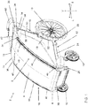
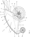
- FIGS. 1-11 , 12A , 12B , 13A, and 13B illustrate a passenger transport carrier 2 according to an embodiment.
- Passenger transport carrier 2 is a device configured to carry a passenger from one place to another.
- the passenger can be, for example, child, a disabled person, or an elderly person.
- Carrier 2 can include a frame assembly that defines a passenger compartment configured to at least partially enclose a passenger.
- Carrier 2 can also include one or more transportation devices, for example, wheels, skis, or any other suitable transportation devices.
- the carrier can be configured to transport at least one passenger, for example, one, two, or three passengers.
- Carrier 2 can be configured either for a single mode of operation (namely, a single-function carrier such as a simple stroller) or for multiple modes of operations (namely, a multi-function carrier).
- a single-function carrier can be configured for one of the following modes of operation: a bicycle mode in which the carrier is pulled by a bicycle; a ski mode in which the carrier is either pulled by a skier; a walking mode in which the carrier is pushed by a user walking; a hiking mode in which the carrier is pulled by a user hiking; and a jogging mode in which the carrier is pushed by a user jogging.
- a multi-function carrier can be configured to be used in at least two of the following modes: the bicycle mode; the ski mode; the walking mode; the hiking mode; and the jogging mode.
- carrier 2 is configured such that the transportation devices, for example, wheels or skis, can be selectively and releasably coupled to the carrier. This way provides the user maximum flexibility by allowing the user to choose the mode.
- carrier 2 has a longitudinal axis L that is generally parallel to the intended direction of travel of the carrier, a transverse axis T that is generally perpendicular to longitudinal axis L, and a vertical axis V that is generally perpendicular to longitudinal axis L and transverse axis T.
- longitudinal and longitudinally, transverse and transversely, and vertical and vertically are relative to longitudinal axis L, transverse axis T, and vertical axis V, respectively.
- carrier 2 is configured to transport one passenger. In some embodiments, carrier 2 is configured to transport a child. In some embodiments, carrier 2 is configured to transport an adult disabled person or an elderly person.
- Carrier 2 includes a frame assembly that provides structural support for carrier 2.
- FIGS. 1-4 and 6-8 illustrate a frame assembly 4 according to an embodiment.
- Frame assembly 4 defines a compartment 6 for containing a passenger.
- frame assembly 4 completely surrounds compartment 6.
- Completely surrounding compartment 6 provides additional protection to a passenger seated within compartment 6, which can be advantageous for carriers configured for ski mode, bicycle mode, hiking mode, and jogging mode.
- frame assembly 4 partially surrounds compartment 6 leaving, for example, the front, sides, and top of compartment 6 open.
- Carrier 2 includes a cover 8 coupled to frame assembly 4.
- Cover 8 shields a passenger that is in compartment 6 from environmental elements, for example, sun, wind, rain, noise, or any other environmental element.
- cover 8 completely surrounds compartment 6 to form a substantially enclosed passenger cabin.
- cover 8 partially surrounds compartment 6 leaving, for example, the front, sides, or top of compartment 6 open.
- cover 8 can be omitted.
- Carrier 2 includes at least one transportation device.
- carrier 2 can include a plurality of wheels 10, for example, two, three, four, or more than four wheels.
- carrier 2 can include non-wheel transportation devices, for example, skis or any other suitable transportation device.
- frame assembly 4 includes a lower frame 12 that defines a lower boundary of passenger compartment 6; an upper frame 14 that defines an upper boundary of passenger compartment 6; a forward frame 16 that defines a forward boundary of passenger compartment 6; and a rear frame 18 that defines a rear boundary of passenger compartment 6.
- one or more of lower frame 12, upper frame 14, forward frame 16, and rear frame 18 can be omitted such that the corresponding boundary of compartment 6 is opened.
- forward frame 16 can be omitted, in some embodiments, such that the front of compartment 6 is opened.
- lower frame 12, upper frame 14, forward frame 16, and rear frame 18 are easily definable and discrete portions of frame assembly 4, two or more of lower frame 12, upper frame 14, forward frame 16, and rear frame 18 can be continuous, integral portions that define multiple boundaries of passenger compartment 6.
- lower frame 12 defines a terminal bottom edge of frame assembly 4; upper frame 14 defines a terminal top edge of frame assembly 4; forward frame 16 defines a terminal front edge of frame assembly 4; and rear frame 18 defines a terminal back edge of frame assembly 4.
- one or more of lower frame 12, upper frame 14, forward frame 16, and rear frame 18 defines an intermediate portion, not a terminal edge of frame assembly 4.
- Lower frame 12 includes one or more frame members made of any suitable material, for example, metal, plastic, composite, or any other suitable material.
- lower frame 12 includes at least two spaced apart elongate lower frame members 24.
- FIGS. 1-3 , 6 , and 7 illustrate a left elongate lower frame member 24, and FIGS. 4 and 8 illustrate a right elongate lower frame member 24.
- Lower frame members 24 extend longitudinally across frame assembly 4 and, in some embodiments, are parallel to longitudinal axis L.
- Lower frame members 24 each have a forward end 26 and a rear end 28, which in some embodiments, define the forward end of frame assembly 4, and the rear end of frame assembly 4 as shown in FIGS. 1-4 and 6-8 .
- lower frame 12 also includes a forward lower frame member 30 that extends transversely across lower frame 12 and is fixedly coupled to forward ends 26 of longitudinal lower frame members 24.
- lower frame 12 also includes rear lower frame member 32 that extends transversely across lower frame 12 and is fixedly coupled to rear ends 28 of longitudinal lower frame members 24.
- lower frame 12 is rectangular when viewed from above in the vertical direction. In other embodiments, lower frame 12 has a non-rectangular shape when viewed from above in the vertical direction.
- Upper frame 14 is positioned above lower frame 12.
- Upper frame 14 includes one or more frame members made of any suitable material, for example, metal, plastic, and composite.
- upper frame 14 includes at least two transversely spaced apart elongate upper frame members 34.
- upper frame 14 includes a left upper frame member 34 on a left side of upper frame 14 and frame assembly 4, and a right upper frame member 34 on the right side of upper frame 14 and frame assembly 4.
- Upper frame members 34 extend longitudinally across upper frame 14 and, in some embodiments, are parallel to longitudinal axis L.
- Upper frame members 34 each have a forward end 36 and a rear end 38. As best seen in FIGS.
- upper frame 14 includes a forward upper frame member 40 that extends transversely across upper frame 14 and is fixedly coupled to forward ends 36 of longitudinal upper frame members 34.
- Upper frame 14 also includes rear frame member 42 that extends transversely across upper frame 14 and is fixedly coupled to rear ends 38 of longitudinal upper frame members 34 as best seen in FIGS. 1 , 2 , 4-6 , 8 , 9 , and 11 .
- upper frame 14 is rectangular when viewed from above in the vertical direction. In other embodiments, upper frame 14 has a non-rectangular shape when viewed from above in the vertical direction.
- At least a portion of upper frame 14 overlaps lower frame 12 in a vertical direction.
- forward ends 36 of upper frame members 34 of upper frame 14 are positioned in front of rear ends 28 of lower frame members 24 of lower frame 12. Accordingly, when a passenger is in compartment 6, at least a portion of the passenger will be vertically between upper frame 14 and lower frame 12.
- at least a portion of upper frame 14 overlaps a seat bottom of a seat (which is described further below) that supports the passenger.
- Forward frame 16 extends between lower frame 12 and upper frame 14.
- Forward frame 16 includes one or more members made of any suitable material, for example, metal, plastic, or composite.
- forward frame 16 includes at least two transversely spaced apart elongate forward frame members 44.
- forward frame 16 includes a left forward frame member 44 on a left side of forward frame 16 and frame assembly 4, and a right forward frame member 44 on the right side of forward frame 16 and frame assembly 4.
- Frame members 44 extend in the vertical direction from lower frame 12 to upper frame 14 and, in some embodiments (not shown), are parallel to vertical axis V.
- Frame members 44 each have a lower end 46 and an upper end 48.
- Lower ends 46 are coupled, for example, fixedly or rotatably, to forward ends 26 of longitudinal lower frame members 24 of lower frame 12.
- Upper ends 48 are coupled, for example, fixedly or rotatably, to forward ends 36 of upper frame members 34 of upper frame 14.
- forward frame members 44 can be arcuate when viewed from the side. In some embodiments (not shown), forward frame members 44 are straight.
- Rear frame 18 extends between lower frame 12 and upper frame 14.
- Rear frame 18 includes one or more frame members made of any suitable material, for example, metal, plastic, or composite.
- rear frame 18 includes at least two transversely spaced apart elongate rear frame members 50.
- rear frame 18 includes a left rear frame member 50 on a left side of rear frame 18 and frame assembly 4, and a right rear frame member 50 on the right side of rear frame 18 and frame assembly 4.
- Rear frame members 50 extend in the vertical direction from lower frame 12 to upper frame 14 and, in some embodiments (not shown), are parallel to vertical axis V.
- Rear frame members 50 each have a lower end 52 and an upper end 54.
- Lower ends 52 are coupled, for example, fixedly or rotatably, to rear ends 28 of lower frame members 24 of lower frame 12.
- Upper ends 54 are coupled, for example, fixedly or rotatably, to rear ends 38 of upper frame members 34 of upper frame 14.
- frame members 50 are straight.
- frame members 50 include a hinge assembly such that a lower portion 56 of rear frame member 50 can rotate relative to an upper portion 58 of rear frame member 50.
- a frame member forming a portion of lower frame 12, upper frame 14, forward frame 16, or rear frame 18 can be the same member forming a portion of the other frame portions.
- forward frame member 44 and longitudinal upper frame member 34 can be formed by the same frame member.
- frame assembly 4 also includes a handle 60 configured to be pushed or manipulated by a user to move carrier 2 in the direction of travel.
- Handle 60 includes ends coupled, rotatably or fixedly, to rear ends 38 of upper frame members 34 of upper frame 14 in some embodiments.
- Handle 60 can be substantially U-shaped when viewed from above in some embodiments.
- frame assembly 4 also includes an upper seat support 20 that is movably coupled to upper frame 14 and configured to support a passenger seat.
- Upper seat support 20 is configured to move between a first seat position, for example, a terminal upright seat position, as shown in FIGS. 2-5 and 11 , and a second seat position, for example, a terminal reclined seat position, as shown in FIGS. 6-9 .
- upper seat support 20 includes a cross-member 68 that extends transversely across frame assembly 4 and carrier 2.
- Cross-member 68 is positioned to be accessible to a user's hand so that a user can grab cross-member 68 and move upper seat support 20 between the first seat position and the second seat position.
- Cross-member 68 has a first end 70 and a second end 72.
- Upper seat support 20 also includes a first elongate member 74 that extends longitudinally from first end 70 of cross-member 68 toward the front end of frame assembly 4.
- Upper seat support 20 also includes a second elongate member 76 that extends longitudinally from second end 72 of cross-member 68 toward the front end of frame assembly 4.
- elongate members 74 and 76 are arcuate when viewed from the side. Collectively, when viewed from above in the vertical direction, elongate members 74 and 76 and cross-member 68 form a U-shape. In other embodiments, elongate members 74 and 76 and cross-member 68 can form a non-U-shape.
- upper frame members 34 of upper frame 14 can each define a channel 62.
- channels 62 each have an opening at rear end 38 of upper frame member 34, and channel 62 has a closed end at forward end 36 of upper frame member 34.
- channels 62 have open ends at forward ends 36 of upper frame members 34.
- upper frame member 34 is a plastic housing made of two combinable halves that collectively define channel 62. In some embodiments, at least a portion of channel 62 overlaps lower frame 12 in the vertical direction. For example, the closed ends of channel 62 can be positioned in front of rear ends 28 of lower frame members 24 of lower frame 12.
- Each upper frame member 34 further defines a forward opening 64 in communication with channel 62 and a spaced rear opening 66 in communication with channel 62.
- forward openings 64 and rear openings 66 correspond to the first seat position and the second seat position, respectively, and operatively stop and lock upper seat support 20 at the first seat position and the second seat position.
- openings 64 and 66 are through holes that extend through the entire wall of upper frame member 34 from channel 62 to the outer surface of upper frame member 34 as shown, for example, in FIGS. 4 , 5 , 8 , and 9 .
- openings 64 and 66 are recesses defined in the internal surface that defines channel 62.
- forward openings 64 are at forward ends 36 of upper frame members 34, and rear openings 64 are at rear ends 38 of upper frame members 34.
- frame members 34 defines one or more openings aligned between forward openings 64 and rear openings 66 that corresponds to one or more additional seat positions of upper seat support 20.
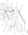
- Channels 62 defined by upper frame members 34 are configured to closely receive elongate members 74 and 76 therein in some embodiments. Elongate members 74 and 76 slide within channels 62 as upper seat support 20 moves relative to upper frame members 34 between the first seat position and the second seat position. For example, in FIGS. 4 and 5 (in which the left upper frame member 34 is removed for illustrative purposes), upper seat support 20 is at the first seat position. At this first seat position, substantially the entire lengths of elongate members 74 and 76 are within channels 62 defined by upper frame members 34. In FIGS. 8 and 9 , (in which the left upper frame member 34 is removed for illustrative purposes), upper seat support 20 is at the second seat position.
- elongate members 74 and 76 include a stop that prevents elongate members 74 and 76 from coming out of channels 62.
- carrier 2 also includes at least one lock configured to lock upper seat support 20 at the first seat position and at the second seat position. In some embodiments, the at least one lock configured to lock upper seat support 20 at discrete positions. In some embodiments, a lock is coupled to one of elongate member 74 and elongate member 76, and configured to be slidably received within a respective channel 62 defined by one of upper frame members 34. In some embodiments, referencing FIGS. 4 , 5 , 8 , and 9 , carrier 2 includes a first lock 78 coupled to the distal end of elongate member 74 of upper seat support 20, and a second lock 80 coupled to the distal end of elongate member 76 of upper seat support 20. First lock 78 and second lock 80 are configured to slide within respective channels 62 of upper frame 14. First lock 78 and second lock 80 are configured collectively to lock upper seat support 20 at the first seat position and at the second seat position.
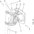
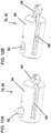
- FIGS. 12A, 12B , 13A, and 13B illustrate an embodiment of first lock 78 and second lock 80.
- Lock 78 or 80 includes a movable locking pin 82 configured to move between (1) a first engaged pin position that locks upper seat support 20 at the first seat position or at the second seat position, and (2) a second disengaged pin position that unlocks upper seat support 20 allowing upper seat support 20 to move between the first seat position and the second seat position.
- Lock 78 or 80 can be configured to be inserted within, for example, at the distal ends, of elongate members 74 and 76 (shown in FIGS. 12A, 12B , 13A, and 13B ), or to be abutted against the distal ends of elongate members 74 and 76 (not shown).
- lock 78 or 80 also includes a housing 84 shaped to closely match the shape of a channel defined by elongate members 74 and 76.
- housing 84 has a corresponding cylindrical shape that matches the channel of elongate members 74 and 76 as shown, for example, in FIGS. 12A and 12B . Accordingly, housing 84 is configured to be received within elongate members 74 and 76 and, thus, slide within channel 62 of frame members 34 as upper seat support 20 moves between the first seat position and the second seat position.
- Housing 84 defines a channel 86 that extends longitudinally across housing 84 and then transversely to create a periphery opening in housing 84.
- Locking pin 82 is slidably coupled within channel 86 such that at the first engaged pin position ( FIGS. 12A and 13A ) the distal end of locking pin 82 extends beyond housing 84 and at the second disengaged pin position ( FIGS. 12B and 13B ) the distal end of locking pin 82 is retracted within housing 84.
- Lock 78 or 80 also includes a sliding member 88 slidably disposed within channel 86 of housing 84.
- sliding member 88 is configured to slide in a direction perpendicular to the movement of locking pin 82.
- Locking pin 82 defines a slot 90 that is angled relative to the direction of travel of sliding member 88.
- Sliding member 88 includes a pin 92 position within slot 90 defined by locking pin 82.
- pin 92 engages slot 90 to retract locking pin 82 within housing 84 of lock 78 or 80 to the second disengaged pin position.
- Lock 78 or 80 also includes a compression spring 94 that biases locking pin 82 towards the first engaged pin position. Accordingly, as sliding member 88 moves toward locking pin 82, pin 92 disengages slot 90, and locking pin 82 moves towards the first engaged pin position such that the distal end of locking pin 82 extends beyond housing 84.
- elongate members 74 and 76 define an opening 95, for example, at their distal ends, as shown in FIGS. 13A and 13B . Opening 95 allows the distal end of locking pin 82 to extend through the wall of elongate members 74 and 76 when locking pin 82 is at the first engaged pin position as shown in FIGS. 12A and 13A .
- Lock 78, 80 fixedly coupled to elongate members 74 and 76 using a dowel pin 96 that extends through the wall of elongate members 74 and 76 and housing 84.
- the distal end of locking pin 82 is configured to be received in the openings 64 and 64 defined by upper frame member 34 to lock upper seat support 20.
- upper frame 14, upper seat support 20, and lock 78 or 80 are configured such that the distal end of locking pin 82 is received in opening 64 when upper seat support 20 is at the first seat position and when and locking pin 82 is at the first engaged pin position.
- Upper seat support 20 is locked at the first seat position at this configuration.
- the cooperation between opening 64 and locking pin 82 may also operate as a stop that prevents elongate members 74 and 76 of upper seat support 20 from moving in a forward longitudinal direction within channels 62 defined by upper frame members 34.
- Upper frame 14, upper seat support 20, and lock 78 or 80 are also configured such that the distal end of locking pin 82 is received in opening 66 when upper seat support 20 is at the second seat position and when and locking pin 82 is at the first engaged pin position. Upper seat support 20 is locked at the second seat position at this configuration. Accordingly, the cooperation between opening 66 and locking pin 82 may also operate as a stop that prevents elongate members 74 and 76 of upper seat support 20 from coming out of channels 62 defined by upper frame members 34.
- locking pin 82 is moved to the second disengaged pin position at which the distal pin is no longer received within either opening 64 or opening 66.
- carrier 2 can also include at least one actuator 98 coupled to first lock 78 and second lock 80 that is configured to engage and/or disengage first lock 78 and second lock 80 (for example, configured to move locking pin 82 between the first engaged pin position and the second disengaged pin position).
- actuator 98 includes a base 100 fixedly coupled to carrier 2, for example, to cross-member 68 of upper seat support 20.
- actuator 98 is positioned, for example, at cross-member 68, such that a user can access actuator 98 to lock or unlock upper seat support 20 from the upper, rear of carrier 2.
- This position provides the user access to actuator 98 while standing in the normal operation position when being used in a walking or jogging mode. That is, the user can access actuator 98 with bending down or moving to the front of carrier 2. This position may also allow the user to easily assist with manually moving upper seat support 20.
- Actuator 98 also includes a lever 102 rotatably coupled to base 100 using a pivot pin 104.
- Lever 102 rotates between a first lever position, for example, at which the distal end of lever 102 is pointed up (not shown), and a second lever position at which the distal end of lever 102 is pointed down as shown in FIGS. 4 , 5 and 8-11 .
- Actuator 98 includes a spring 106 configured to bias lever 102 towards the first lever position.
- Actuator 98 also includes a first cable 108 having a first end 110 fixedly coupled to lever 102. First cable 108 is fed within the channels defined by cross-member 68 and first elongate member 74 to first lock 78.
- first cable 108 is coupled to first lock 78, for example, directly to sliding member 88.
- Actuator 98 also includes a second cable 112 (shown in FIG. 11 ) having a first end 114 fixedly coupled to lever 102. Second cable 112 is fed within the channels defined by cross-member 68 and second elongate member 76 to second lock 80. The other end 118 of second cable 112 is coupled to second lock 80, for example, directly to sliding member 88.
- lever 102 rotates between the first lever position and the second lever position, lever 102 pulls first cable 108 and second cable 112, which in turn pulls sliding member 88 of first lock 78 and sliding member 88 of second lock 80, respectively.
- a single actuator 98 is configured to simultaneously disengage first lock 78 and second lock 80.
- carrier 2 can have two separate actuators 98 that independently operate first lock 78 and second lock 80.
- actuator 98 instead of using two separate cables 108 and 112, actuator 98 includes a single cable that is coupled to first lock 78 and second lock 80 at the ends of the cable and to lever 102 at an intermediate portion of the cable.
- carrier 2 can also include a seat configured to support a passenger within compartment 6.
- the seat can include a seat back 120 and a seat bottom 122 in some embodiments.
- Seat back 120 is configured to support the back of the passenger within compartment 6, and seat bottom 122 is configured to support the bottom of the passenger within compartment 6.
- Seat back 120 includes a lower end 124 and an upper end 126.
- Upper end 126 of seat back 120 is coupled to upper seat support 20.
- upper end 126 of seat back 120 can be wrapped around cross-member 68 of upper seat support 20.
- Lower end 124 of seat back 120 is coupled to frame assembly 4.
- lower frame 12 includes a rear lower frame member 132 extending transversely across lower frame 12 and fixedly coupled to longitudinal lower frame members 24, and lower end 124 of seat back 120 is coupled to rear lower frame member 132. Accordingly, as upper seat support 20 moves between the first seat position and the second seat position, seat back 120 rotates about a transverse axis defined by rear lower frame member 132 to which lower end 124 of seat back 120 is coupled.
- seat back 120 is only coupled to upper seat support 20 and rear lower frame member 132. That is, no frame members, including vertically extending frame members, are coupled to seat back 120 between upper seat support 20 and rear lower frame member 132.
- This configuration may allow carrier 2, including seat back 120, to be easily folded. This configuration may also help reduce the weight and cost of manufacturing carrier 2.
- Seat bottom 122 includes a forward end 128 and a rear end 130. Forward end 128 of seat bottom 122 and rear end 130 of seat bottom 122 are coupled to frame assembly 4.
- lower frame 12 includes a forward lower frame member 134 extending transversely across lower frame 12 and fixedly coupled to longitudinal lower frame members 24. Forward end 128 of seat bottom 122 is coupled to forward lower frame member 134, and rear end 130 of seat bottom 122 is fixedly coupled to rear lower frame member 132. Accordingly, as seat back 120 rotates between the first seat position and the second seat position, seat bottom 122 remains stationary. Because seat bottom 122 remains stationary, the leg room for a passenger's legs does not change between the first seat position and the second seat position.
- seat back 120 and seat bottom 122 are made of a flexible material or any other suitable material. In some embodiments, seat back 120 and seat bottom 122 are formed from separate panels of material. In some embodiments, seat back 120 and seat bottom 122 are formed from a single panel of material.
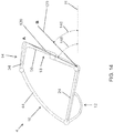
- FIG. 14 schematically illustrates frame assembly 4, according to an embodiment, in which upper seat support 20 is at the first seat position A, namely, the upright seat position, and at the second seat position B, namely, the relaxed seat position.
- an angle 146 between seat back 120 and a horizontal plane H ranges from about 50 degrees to about 80 degrees. In some embodiments, angle 146 ranges from about 60 degrees to about 70 degrees. In some embodiments, angle 146 is about 65 degrees.
- an angle 148 between seat back 120 and horizontal plane H ranges from about 30 degrees to about 60 degrees. In some embodiments, angle 148 ranges from about 40 degrees to about 50 degrees.
- angle 148 is about 45 degrees. In some embodiments, the difference between angle 146 and angle 148 ranges from about 10 degrees to about 30 degrees. In some embodiments, the difference between angle 146 and angle 148 ranges from about 15 degrees to about 25 degrees. In some embodiments, the difference between angle 146 and angle 148 ranges is about 20 degrees.
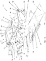
- FIG. 15 illustrates a frame assembly 135 according to another embodiment.
- frame assembly 135 is configured to transport a plurality of passengers within compartment 6 using a plurality of seats.
- Frame assembly 135 is substantially similar to frame assembly 4 illustrated in FIGS. 1-13 , and FIG. 15 uses like reference numbers to generally indicate identical, functionally similar, and/or structurally similar elements. These similar components are only discussed to the extent they may differ from the components of frame assembly 4 or needed to describe the embodiment.
- upper frame 14 of frame assembly 135 includes at least three spaced apart elongate upper frame members 34 that extend longitudinally across frame assembly 135.
- the two outer upper frame members 34 each define a single channel 62, and the middle upper frame member 34 defines two channels 62.
- Each of these channels has an opening at rear end 38 of frame members 34 of upper frame 14, and has closed ends at forward ends 36 of frame members 34.
- Frame assembly 135 includes a first upper seat support 20 movably coupled to upper frame 14 and a second upper seat support 22 movably coupled to upper frame 14.
- Second upper seat support 22 is configured to move independently from first upper seat support 20.
- Second upper seat support 22 can be constructed similarly to first upper seat support 20 described above.
- the channel defined by the left upper frame members 34 of upper frame 14 and one of the channels defined by the middle upper frame member 34 can be configured to closely receive elongate members 74 and 76 of first upper seat support 22 therein.
- the other channel defined by the middle upper frame member 34 of upper frame 14 and the channel defined by the right upper frame member 34 can be configured to closely receive elongate members 74 and 76 (which are enclosed within the middle upper frame member 34 and the right upper frame member 34 in FIG. 15 ) of second upper seat support 22 therein.
- Elongate members 74 and 76 of first seat support 20 slide within the channels of the left and middle upper frame members 34 as upper seat support 20 moves relative to frame members 34 between a first seat position and a second seat position.
- Elongate members 74 and 76 of second seat support 22 slide within the channels of the middle and right upper frame members 34 as upper seat support 22 moves relative to frame members 34 between a first seat position and a second seat position independent of first upper seat support 20.
- a separate seat including seat back 120 and seat bottom 122 is coupled to each of upper seat support 20 and second upper seat support 22.
- FIG. 16 illustrates another embodiment of an upper seat support 147.
- Upper seat support 147 is substantially similar to upper seat support 20 described above. Accordingly, FIG. 16 uses like reference numbers to generally indicate identical, functionally similar, and/or structurally similar elements. These similar components are only discussed to the extent they may differ from the components of upper seat support 20 or needed to describe the embodiment.
- cross-member 68 is rotatably coupled to first elongate member 74 at first end 70 and rotatably coupled to second elongate member 76 at second end 72, and cross-member 68 forms a portion of the actuator configured to engage or disengage first lock 78 and second lock 80.
- first cable 108 is fixedly coupled to cross-member 68
- end 114 of second cable 108 is fixedly coupled to cross-member 68.
- cross-member 68 rotates, for example, in the direction indicated by the arrow in FIG. 16
- cross-member 68 pulls first and second cables 108 and 112, which in turn pulls sliding members 88 of first lock 78 and second lock 80.
- sliding members 88 of first and second locks 78 and 80 are pulled, the locking pin 82 of locks 78 and 80 moves from the first engaged pin position to the second disengaged pin position.
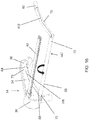
- FIG. 17 illustrates another embodiment of an upper frame 150 and an upper seat support 136.
- Upper frame 150 and upper seat support 136 are substantially similar to upper frame 14 and upper seat support 20 described above. Accordingly, FIG. 17 uses like reference numbers to generally indicate identical, functionally similar, and/or structurally similar elements. These similar components are only discussed to the extent they may differ from the components of upper seat support 20 or needed to describe the embodiment.
- Upper seat support 136 includes a cross-member 138 that extends transversely across upper frame 14 of frame assembly 4 and carrier 2. Cross-member 138 is positioned to be accessible to a user's hand during use.
- Upper seat support 20 also includes a first elongate member 140 that extends longitudinally from an intermediate portion of cross-member 138 toward a front end of upper frame 150.
- elongate member 140 is arcuate when viewed from the side. Collectively, when viewed from above in the vertical direction, upper seat support 136 has a T-shape. In other embodiments, elongate members 74 and 76 and cross-member 68 can form a non-T-shape. As shown in FIG. 17 , transverse frame member 42 of upper frame 14 includes a portion 142 that projects downward from frame member 42. Projecting portion 142 defines a channel 144 configured to closely receive elongate member 140 therein. Elongate member 140 slides within channel 144 as upper seat support 136 is moved relative to upper frame 14 between the first seat position (not shown) and the second seat position (shown in FIG. 17 ).
- a user places one hand on actuator 98.
- the user places the other hand on either frame member 42 or handle 60 to secure carrier 2.
- the user only uses one hand to operate frame assembly 4 to move upper seat support 20 from one seat position to another, namely, the hand operating actuator 98.
- the user then rotates lever 102 from the first lever position to the second lever position, which pulls first cable 108 and second cable 112, which in turn pulls sliding members 88 of first lock 78 and second lock 80 away from locking pin 82.
- locking pins 82 move from (1) the first engaged pin position at which the distal ends of locking pins 82 are received within openings 64 defined by upper frame members 34 to (2) the second disengaged pin position at which the distal ends of locking pins 82 are no longer received within openings 64, disengaging first lock 78 and second lock 80 and unlocking upper seat support 20.
- grabbed lever 102 of actuator 98 the user grabs upper seat support 20, while still holding frame member 42 or handle 60 with the other hand, and pulls upper seat support 20 to the second seat position.
- springs 94 push locking pins 82 of first lock 78 and second lock 80 from the second disengaged pin position to the first engaged pin position at which locking pins 82 are received within openings 66 defined by upper frame members 34, engaging first lock 78 and second lock 80 and locking upper seat support 20 at the second seat position.
Landscapes
- Engineering & Computer Science (AREA)
- Transportation (AREA)
- Mechanical Engineering (AREA)
- Chemical & Material Sciences (AREA)
- Combustion & Propulsion (AREA)
- Health & Medical Sciences (AREA)
- Public Health (AREA)
- Child & Adolescent Psychology (AREA)
- General Health & Medical Sciences (AREA)
- Environmental & Geological Engineering (AREA)
- Seats For Vehicles (AREA)
- Handcart (AREA)
Claims (12)
- Voiture de transport d'enfant (2) comprenant :un châssis inférieur (12) présentant une première extrémité et une deuxième extrémité,un châssis supérieur (14) présentant une première coulisse (62) définie dans celui-ci, une première extrémité et une deuxième extrémité,un châssis avant (16) compris entre la première extrémité du châssis inférieur (12) et la première extrémité du châssis supérieur (14), etun premier support supérieur de siège (20) comprenant :une traverse (68) s'étendant dans la largeur de la voiture (2) et présentant une première extrémité (70) et une deuxième extrémité (72), etun premier élément allongé (74) s'étendant longitudinalement à partir de la première extrémité de la traverse (68) du premier support supérieur de siège (20) et reçu coulissant dans la première coulisse (62) du châssis supérieur (14) ;le premier support supérieur de siège (20) étant conçu pour adopter une première position de siège (A) ou une deuxième position de siège (B) ; caractérisée en ce que la voiture comprendun châssis arrière (18) compris entre la deuxième extrémité du châssis inférieur (12) et la deuxième extrémité du châssis supérieur (14).
- Voiture (2) selon la revendication 1, comprenant en outre un premier dispositif de verrouillage (78) couplé au premier support supérieur de siège (20) et conçu pour verrouiller le premier support supérieur de siège (20) dans la première position de siège (A) et dans la deuxième position de siège (B).
- Voiture (2) selon la revendication 2, dans laquelle le premier dispositif de verrouillage (78) est couplé au premier élément allongé (74) du premier support supérieur de siège (20) et est reçu coulissant dans la première coulisse (62) du châssis supérieur (14).
- Voiture (2) selon la revendication 2, comprenant en outre un actionneur (98) couplé au premier dispositif de verrouillage (78) et conçu pour activer ou désactiver le premier dispositif de verrouillage (78).
- Voiture (2) selon la revendication 2, dans laquelle le premier dispositif de verrouillage (78) comprend une première broche de verrouillage (82) mobile, et dans laquelle le châssis supérieur (14) définit en outre une première ouverture (64) conçue pour recevoir la première broche de verrouillage (82) lorsque le premier support supérieur de siège (20) se trouve dans la première position de siège (A) et une deuxième ouverture (66) conçue pour recevoir la première broche de verrouillage (82) lorsque le premier support supérieur de siège (20) se trouve dans la deuxième position de siège (B).
- Voiture (2) selon la revendication 5, dans laquelle les première et deuxième ouvertures (64, 66) traversent totalement une paroi du châssis supérieur (14).
- Voiture (2) selon la revendication 1, dans laquelle le châssis supérieur (14) présente une deuxième coulisse (62) définie dans celui-ci ; le premier support supérieur de siège (20) comprenant en outre un deuxième élément allongé (76) partant de la deuxième extrémité de la traverse (68) du premier support supérieur de siège (20) et reçu coulissant dans la deuxième coulisse (62) du châssis supérieur (14).
- Voiture (2) selon la revendication 7, dans la mesure où elle dépend de la revendication 2, comprenant en outre :un deuxième dispositif de verrouillage (80) couplé au deuxième élément allongé (76) du premier support supérieur de siège (20), reçu coulissant dans la deuxième coulisse (62) du châssis supérieur (14) et conçu pour verrouiller le premier support supérieur de siège (20) dans la première position de siège (A) et dans la deuxième position de siège (B), etun actionneur (98) couplé au premier dispositif de verrouillage (78) et au deuxième dispositif de verrouillage (80) et conçu pour activer ou désactiver simultanément le premier dispositif de verrouillage (78) et le deuxième dispositif de verrouillage (80).
- Voiture (2) selon la revendication 1, dans laquelle le châssis supérieur (14) présente une deuxième coulisse (62) définie dans celui-ci ;
un deuxième support supérieur de siège (22) comprenant :une deuxième traverse (68) s'étendant dans la largeur de la voiture (2) et présentant une première extrémité et une deuxième extrémité, etun premier élément allongé (74) partant de la première extrémité de la deuxième traverse (68) du deuxième support supérieur de siège (22) et reçu coulissant dans la deuxième coulisse (62) du châssis supérieur (14) ;ledit deuxième support supérieur de siège (22) étant conçu pour adopter une première position de siège (A) ou une deuxième position de siège (B) indépendamment du premier support supérieur de siège (20). - Voiture (2) selon la revendication 1, comprenant en outre un siège conçu pour accueillir un enfant et comprenant un dossier de siège (120) couplé au premier support supérieur de siège (20) et une assise (122) demeurant stationnaire tandis que le premier support supérieur de siège (20) adopte la première position de siège (A) ou la deuxième position de siège (B).
- Voiture (2) selon la revendication 1, dans laquelle la première extrémité du châssis supérieur (14) est en avant de la deuxième extrémité du châssis inférieur (12) lorsque le premier support supérieur de siège (20) se trouve dans la première position de siège (A) et dans la deuxième position de siège (B).
- Voiture (2) selon la revendication 1, ladite voiture (2) étant conçue pour une utilisation selon au moins deux des modes suivants : un mode vélo, un mode ski, un mode marche, un mode randonnée et un mode jogging.
Priority Applications (2)
| Application Number | Priority Date | Filing Date | Title |
|---|---|---|---|
| EP22190990.6A EP4201786A1 (fr) | 2014-11-26 | 2015-11-19 | Supports de transport de passagers |
| EP19163954.1A EP3524491B1 (fr) | 2014-11-26 | 2015-11-19 | Supports de transport de passagers |
Applications Claiming Priority (2)
| Application Number | Priority Date | Filing Date | Title |
|---|---|---|---|
| US201462084992P | 2014-11-26 | 2014-11-26 | |
| PCT/IB2015/058986 WO2016083962A1 (fr) | 2014-11-26 | 2015-11-19 | Supports de transport de passagers |
Related Child Applications (3)
| Application Number | Title | Priority Date | Filing Date |
|---|---|---|---|
| EP19163954.1A Division EP3524491B1 (fr) | 2014-11-26 | 2015-11-19 | Supports de transport de passagers |
| EP19163954.1A Division-Into EP3524491B1 (fr) | 2014-11-26 | 2015-11-19 | Supports de transport de passagers |
| EP22190990.6A Division EP4201786A1 (fr) | 2014-11-26 | 2015-11-19 | Supports de transport de passagers |
Publications (3)
| Publication Number | Publication Date |
|---|---|
| EP3224112A1 EP3224112A1 (fr) | 2017-10-04 |
| EP3224112A4 EP3224112A4 (fr) | 2018-02-07 |
| EP3224112B1 true EP3224112B1 (fr) | 2019-07-10 |
Family
ID=56073702
Family Applications (3)
| Application Number | Title | Priority Date | Filing Date |
|---|---|---|---|
| EP15863251.3A Active EP3224112B1 (fr) | 2014-11-26 | 2015-11-19 | Supports de transport de passagers |
| EP22190990.6A Withdrawn EP4201786A1 (fr) | 2014-11-26 | 2015-11-19 | Supports de transport de passagers |
| EP19163954.1A Active EP3524491B1 (fr) | 2014-11-26 | 2015-11-19 | Supports de transport de passagers |
Family Applications After (2)
| Application Number | Title | Priority Date | Filing Date |
|---|---|---|---|
| EP22190990.6A Withdrawn EP4201786A1 (fr) | 2014-11-26 | 2015-11-19 | Supports de transport de passagers |
| EP19163954.1A Active EP3524491B1 (fr) | 2014-11-26 | 2015-11-19 | Supports de transport de passagers |
Country Status (6)
| Country | Link |
|---|---|
| US (4) | US10328965B2 (fr) |
| EP (3) | EP3224112B1 (fr) |
| CN (1) | CN107207027B (fr) |
| CA (1) | CA2969079C (fr) |
| DE (1) | DE202015009985U1 (fr) |
| WO (1) | WO2016083962A1 (fr) |
Cited By (1)
| Publication number | Priority date | Publication date | Assignee | Title |
|---|---|---|---|---|
| US11332180B2 (en) | 2020-01-29 | 2022-05-17 | Guava Family, Inc. | Stroller having compact folding and suspension system |
Families Citing this family (4)
| Publication number | Priority date | Publication date | Assignee | Title |
|---|---|---|---|---|
| EP3224112B1 (fr) * | 2014-11-26 | 2019-07-10 | Thule Canada Inc. | Supports de transport de passagers |
| US11148560B1 (en) | 2018-07-05 | 2021-10-19 | Burley Design Llc | Bicycle trailer seat recline |
| US11447168B1 (en) * | 2021-07-02 | 2022-09-20 | Ferrergari LLC. | Motorized stroller having a platform and ergonomic means |
| US12479350B1 (en) * | 2021-08-25 | 2025-11-25 | Sahier Elkhattib | Mobile collection and distribution cart |
Family Cites Families (48)
| Publication number | Priority date | Publication date | Assignee | Title |
|---|---|---|---|---|
| US1729055A (en) * | 1927-03-03 | 1929-09-24 | Bilt Rite Baby Carriage Co | Baby carriage |
| US1663149A (en) * | 1927-04-22 | 1928-03-20 | Frederick D Tryon | Adjustable back rest for baby carriages |
| US1758895A (en) * | 1927-06-06 | 1930-05-13 | F A Whitney Carriage Company | Baby carriage |
| US1719571A (en) * | 1927-09-17 | 1929-07-02 | Heywood Wakefield Co | Adjustable reclining back |
| US4089543A (en) * | 1975-12-04 | 1978-05-16 | Arnie Osborne | Baby carriage |
| US4577355A (en) * | 1983-08-22 | 1986-03-25 | Kassai Kabushikikaisha | Frame structure for baby carriage bed |
| GB2169793B (en) * | 1985-01-14 | 1988-05-25 | Maclaren Ltd Andrews | Reclining mechanism for a baby carriage |
| IT206571Z2 (it) * | 1986-04-23 | 1987-08-10 | Perego Pines Gmbh | Passeggino pieghevole perfezionato per bambini. |
| JPH0775984B2 (ja) * | 1990-10-05 | 1995-08-16 | コンビ株式会社 | ベビーカーのリクライニング若しくは倒伏機構 |
| US5240265A (en) * | 1992-10-23 | 1993-08-31 | Huang Ming Tai | Joint for mounting a backrest support on a stroller frame |
| IT230530Y1 (it) * | 1993-11-29 | 1999-06-07 | Perego Pines Gmbh | Passeggino con regolazione dello schienale a comando centralizzato |
| JP3416329B2 (ja) * | 1994-10-20 | 2003-06-16 | アップリカ▲葛▼西株式会社 | 子供用座席装置 |
| GB9501538D0 (en) * | 1995-01-26 | 1995-03-15 | Kallmeier Paul M | Movement of pushchair seat unit |
| US5669625A (en) * | 1995-03-29 | 1997-09-23 | Jane, S.A. | Folding child's pushchair |
| US5806877A (en) * | 1996-08-28 | 1998-09-15 | Huang; Li-Chu Chen | Adjustable back structure of a stroller |
| US5984332A (en) | 1998-02-27 | 1999-11-16 | Beaudoin; Maurice | Collapsible trailer for a bicycle or similar vehicle |
| ES2216422T3 (es) * | 1998-11-24 | 2004-10-16 | THOMAS HILFEN HILBEG GMBH & CO. KOMMANDITGESELLSCHAFT | Asiento para un carro deslizante, silla o similar. |
| US6322097B1 (en) * | 2000-06-14 | 2001-11-27 | Red Lan | Stroller |
| US6530591B2 (en) * | 2001-08-07 | 2003-03-11 | Mien Chen Huang | Double-seat frame structure for baby stroller |
| JP3986826B2 (ja) * | 2002-01-15 | 2007-10-03 | コンビ株式会社 | リクライニング機構付ベビーカー |
| US6676140B1 (en) * | 2002-04-19 | 2004-01-13 | Darnell M. Gondobintoro | Expandable stroller |
| US6830254B2 (en) * | 2003-02-03 | 2004-12-14 | Red Lan | Stroller with an adjustable backrest |
| US20050029855A1 (en) * | 2003-03-31 | 2005-02-10 | Hanson Wayne H. | Dynamic seating system for personal mobility vehicle |
| US20040189076A1 (en) * | 2003-03-31 | 2004-09-30 | Hanson Wayne H. | Seating assembly for wheelchairs and strollers |
| CA2435076A1 (fr) * | 2003-07-11 | 2005-01-11 | Red Lan | Poussette a dossier reglable |
| CN2794961Y (zh) * | 2005-05-18 | 2006-07-12 | 好孩子儿童用品有限公司 | 靠背角度可调节的儿童推车 |
| CN2915623Y (zh) * | 2006-05-26 | 2007-06-27 | 蔚冠五金制品(深圳)有限公司 | 婴儿车改良结构 |
| DE202006012430U1 (de) | 2006-08-11 | 2006-10-12 | Hauck Gmbh & Co. Kg | Fahrgestell für einen Kinderwagen, eine Kinderkarre o.dgl. |
| CN101362466A (zh) * | 2007-08-08 | 2009-02-11 | 好孩子儿童用品有限公司 | 座兜角度可调节的儿童推车 |
| US8070180B2 (en) * | 2008-06-24 | 2011-12-06 | Leslie Stiba | Stroller and shopping cart |
| NL2002138C (nl) * | 2008-10-24 | 2010-04-27 | Royalty Bugaboo Gmbh | Kinderwagen en opbergelement daarvoor. |
| CN201538348U (zh) * | 2009-03-26 | 2010-08-04 | 宝钜儿童用品香港股份有限公司 | 儿童座椅 |
| CN102107673B (zh) * | 2009-12-25 | 2015-04-08 | 明门香港股份有限公司 | 承载配件、设有承载配件的婴儿承载装置、及其组装方法 |
| US8616638B2 (en) * | 2010-01-15 | 2013-12-31 | Wonderland Nurserygoods Company Limited | Infant carrier apparatus having multiple seating positions |
| US20110175306A1 (en) * | 2010-01-19 | 2011-07-21 | Chicco Usa, Inc. | Reclinable stroller seat |
| CN102258291B (zh) * | 2010-05-28 | 2013-10-16 | 明门香港股份有限公司 | 具多向使用状态的婴儿承载装置及其操作方法 |
| US8596670B2 (en) * | 2010-06-18 | 2013-12-03 | Ascanio Carimati DI CARIMATE | Stroller |
| CN102416975B (zh) * | 2010-09-27 | 2016-06-29 | 明门香港股份有限公司 | 婴儿承载装置及其背靠组件的调整方法 |
| US8991929B2 (en) * | 2012-05-01 | 2015-03-31 | Graco Children's Products Inc. | Stroller seat with articulating calf support |
| DE202012004462U1 (de) * | 2012-05-08 | 2012-07-11 | Kindercar Gmbh | Fahrradanhänger für den Transport von Kindern |
| EP2684765B1 (fr) * | 2012-07-13 | 2015-01-21 | Thule Child Transport Systems Ltd | Agencement de roue avant de support de passager |
| US9868456B2 (en) * | 2012-10-31 | 2018-01-16 | Austlen Baby Co. | Stroller with secondary seating |
| CN104859699B (zh) * | 2014-02-20 | 2017-04-12 | 明门香港股份有限公司 | 儿童推车 |
| DE202014105063U1 (de) * | 2014-10-22 | 2015-01-21 | Curt Würstl Vermögensverwaltungs-GmbH & Co. KG | Sitz für einen Kinderwagen und/oder Puppenwagen |
| EP3224112B1 (fr) * | 2014-11-26 | 2019-07-10 | Thule Canada Inc. | Supports de transport de passagers |
| CN204368236U (zh) * | 2015-01-04 | 2015-06-03 | 好孩子儿童用品有限公司 | 一种儿童座兜 |
| USD811949S1 (en) * | 2015-08-20 | 2018-03-06 | Austlen Baby Co. | Stroller system with an expandable base |
| US20190135323A1 (en) * | 2016-03-07 | 2019-05-09 | Tamooz C.S. Ltd. | Convertible Stroller |
-
2015
- 2015-11-19 EP EP15863251.3A patent/EP3224112B1/fr active Active
- 2015-11-19 DE DE202015009985.8U patent/DE202015009985U1/de not_active Expired - Lifetime
- 2015-11-19 CA CA2969079A patent/CA2969079C/fr active Active
- 2015-11-19 CN CN201580064629.5A patent/CN107207027B/zh active Active
- 2015-11-19 US US15/529,442 patent/US10328965B2/en active Active
- 2015-11-19 EP EP22190990.6A patent/EP4201786A1/fr not_active Withdrawn
- 2015-11-19 EP EP19163954.1A patent/EP3524491B1/fr active Active
- 2015-11-19 WO PCT/IB2015/058986 patent/WO2016083962A1/fr not_active Ceased
-
2019
- 2019-04-30 US US16/399,556 patent/US11325633B2/en active Active
-
2022
- 2022-05-06 US US17/738,704 patent/US11745781B2/en active Active
-
2023
- 2023-03-17 US US18/185,860 patent/US20230227092A1/en not_active Abandoned
Non-Patent Citations (1)
| Title |
|---|
| None * |
Cited By (2)
| Publication number | Priority date | Publication date | Assignee | Title |
|---|---|---|---|---|
| US11332180B2 (en) | 2020-01-29 | 2022-05-17 | Guava Family, Inc. | Stroller having compact folding and suspension system |
| US12179825B2 (en) | 2020-01-29 | 2024-12-31 | Guava Family, Inc. | Stroller having compact folding and suspension system |
Also Published As
| Publication number | Publication date |
|---|---|
| EP3524491A1 (fr) | 2019-08-14 |
| WO2016083962A1 (fr) | 2016-06-02 |
| US11325633B2 (en) | 2022-05-10 |
| US10328965B2 (en) | 2019-06-25 |
| CN107207027A (zh) | 2017-09-26 |
| EP3224112A1 (fr) | 2017-10-04 |
| EP3524491B1 (fr) | 2022-08-24 |
| EP4201786A1 (fr) | 2023-06-28 |
| US20170361861A1 (en) | 2017-12-21 |
| US11745781B2 (en) | 2023-09-05 |
| CA2969079A1 (fr) | 2016-06-02 |
| CA2969079C (fr) | 2022-03-08 |
| CN107207027B (zh) | 2020-01-10 |
| US20230055485A1 (en) | 2023-02-23 |
| US20230227092A1 (en) | 2023-07-20 |
| EP3224112A4 (fr) | 2018-02-07 |
| DE202015009985U1 (de) | 2022-05-31 |
| US20190256123A1 (en) | 2019-08-22 |
Similar Documents
| Publication | Publication Date | Title |
|---|---|---|
| US11745781B2 (en) | Passenger transport carriers | |
| US9380760B2 (en) | Folding pet ramp and steps device with telescoping handle | |
| EP2768698B1 (fr) | Siège-bébé roulant | |
| US7871099B2 (en) | Collapsible pushchair | |
| EP2323888B1 (fr) | Poussette | |
| US6676140B1 (en) | Expandable stroller | |
| EP2830455B1 (fr) | Dispositif de bagage | |
| US8727655B2 (en) | Folding chair safety lock | |
| US20160114705A1 (en) | Child safety seat | |
| US10315681B2 (en) | Compact folding baby stroller | |
| CN104349939A (zh) | 车辆存储舱组件 | |
| EP3831247A1 (fr) | Berceau pliable | |
| US20170297458A1 (en) | Vehicle seat adjustment system | |
| JP6027367B2 (ja) | 折り畳み式手押し車 | |
| US20170360218A1 (en) | Apparatus and method for a foldable child containment system | |
| GB2553886A (en) | Apparatus and method for a foldable child containment system | |
| HUE033410T2 (en) | Suitcase | |
| CN210310520U (zh) | 婴儿车的车架和婴儿车 | |
| JP3834919B2 (ja) | 車両の荷室構造 | |
| CN224061036U (zh) | 可调整婴儿车组合件及用于婴儿车组合件的座椅 | |
| ITBO20130637A1 (it) | Apparato di trasporto |
Legal Events
| Date | Code | Title | Description |
|---|---|---|---|
| STAA | Information on the status of an ep patent application or granted ep patent |
Free format text: STATUS: THE INTERNATIONAL PUBLICATION HAS BEEN MADE |
|
| PUAI | Public reference made under article 153(3) epc to a published international application that has entered the european phase |
Free format text: ORIGINAL CODE: 0009012 |
|
| STAA | Information on the status of an ep patent application or granted ep patent |
Free format text: STATUS: REQUEST FOR EXAMINATION WAS MADE |
|
| 17P | Request for examination filed |
Effective date: 20170508 |
|
| AK | Designated contracting states |
Kind code of ref document: A1 Designated state(s): AL AT BE BG CH CY CZ DE DK EE ES FI FR GB GR HR HU IE IS IT LI LT LU LV MC MK MT NL NO PL PT RO RS SE SI SK SM TR |
|
| AX | Request for extension of the european patent |
Extension state: BA ME |
|
| REG | Reference to a national code |
Ref country code: DE Ref legal event code: R079 Ref document number: 602015033743 Country of ref document: DE Free format text: PREVIOUS MAIN CLASS: B62B0007040000 Ipc: B62B0009100000 |
|
| A4 | Supplementary search report drawn up and despatched |
Effective date: 20180110 |
|
| RIC1 | Information provided on ipc code assigned before grant |
Ipc: B62B 9/10 20060101AFI20180104BHEP |
|
| DAV | Request for validation of the european patent (deleted) | ||
| DAX | Request for extension of the european patent (deleted) | ||
| GRAP | Despatch of communication of intention to grant a patent |
Free format text: ORIGINAL CODE: EPIDOSNIGR1 |
|
| STAA | Information on the status of an ep patent application or granted ep patent |
Free format text: STATUS: GRANT OF PATENT IS INTENDED |
|
| INTG | Intention to grant announced |
Effective date: 20190213 |
|
| GRAS | Grant fee paid |
Free format text: ORIGINAL CODE: EPIDOSNIGR3 |
|
| GRAA | (expected) grant |
Free format text: ORIGINAL CODE: 0009210 |
|
| STAA | Information on the status of an ep patent application or granted ep patent |
Free format text: STATUS: THE PATENT HAS BEEN GRANTED |
|
| AK | Designated contracting states |
Kind code of ref document: B1 Designated state(s): AL AT BE BG CH CY CZ DE DK EE ES FI FR GB GR HR HU IE IS IT LI LT LU LV MC MK MT NL NO PL PT RO RS SE SI SK SM TR |
|
| REG | Reference to a national code |
Ref country code: GB Ref legal event code: FG4D |
|
| REG | Reference to a national code |
Ref country code: CH Ref legal event code: EP Ref country code: AT Ref legal event code: REF Ref document number: 1153273 Country of ref document: AT Kind code of ref document: T Effective date: 20190715 |
|
| REG | Reference to a national code |
Ref country code: DE Ref legal event code: R096 Ref document number: 602015033743 Country of ref document: DE |
|
| REG | Reference to a national code |
Ref country code: IE Ref legal event code: FG4D |
|
| REG | Reference to a national code |
Ref country code: NL Ref legal event code: FP |
|
| REG | Reference to a national code |
Ref country code: SE Ref legal event code: TRGR |
|
| REG | Reference to a national code |
Ref country code: LT Ref legal event code: MG4D |
|
| REG | Reference to a national code |
Ref country code: AT Ref legal event code: MK05 Ref document number: 1153273 Country of ref document: AT Kind code of ref document: T Effective date: 20190710 |
|
| PG25 | Lapsed in a contracting state [announced via postgrant information from national office to epo] |
Ref country code: FI Free format text: LAPSE BECAUSE OF FAILURE TO SUBMIT A TRANSLATION OF THE DESCRIPTION OR TO PAY THE FEE WITHIN THE PRESCRIBED TIME-LIMIT Effective date: 20190710 Ref country code: AT Free format text: LAPSE BECAUSE OF FAILURE TO SUBMIT A TRANSLATION OF THE DESCRIPTION OR TO PAY THE FEE WITHIN THE PRESCRIBED TIME-LIMIT Effective date: 20190710 Ref country code: HR Free format text: LAPSE BECAUSE OF FAILURE TO SUBMIT A TRANSLATION OF THE DESCRIPTION OR TO PAY THE FEE WITHIN THE PRESCRIBED TIME-LIMIT Effective date: 20190710 Ref country code: PT Free format text: LAPSE BECAUSE OF FAILURE TO SUBMIT A TRANSLATION OF THE DESCRIPTION OR TO PAY THE FEE WITHIN THE PRESCRIBED TIME-LIMIT Effective date: 20191111 Ref country code: BG Free format text: LAPSE BECAUSE OF FAILURE TO SUBMIT A TRANSLATION OF THE DESCRIPTION OR TO PAY THE FEE WITHIN THE PRESCRIBED TIME-LIMIT Effective date: 20191010 Ref country code: LT Free format text: LAPSE BECAUSE OF FAILURE TO SUBMIT A TRANSLATION OF THE DESCRIPTION OR TO PAY THE FEE WITHIN THE PRESCRIBED TIME-LIMIT Effective date: 20190710 Ref country code: NO Free format text: LAPSE BECAUSE OF FAILURE TO SUBMIT A TRANSLATION OF THE DESCRIPTION OR TO PAY THE FEE WITHIN THE PRESCRIBED TIME-LIMIT Effective date: 20191010 |
|
| PG25 | Lapsed in a contracting state [announced via postgrant information from national office to epo] |
Ref country code: AL Free format text: LAPSE BECAUSE OF FAILURE TO SUBMIT A TRANSLATION OF THE DESCRIPTION OR TO PAY THE FEE WITHIN THE PRESCRIBED TIME-LIMIT Effective date: 20190710 Ref country code: GR Free format text: LAPSE BECAUSE OF FAILURE TO SUBMIT A TRANSLATION OF THE DESCRIPTION OR TO PAY THE FEE WITHIN THE PRESCRIBED TIME-LIMIT Effective date: 20191011 Ref country code: RS Free format text: LAPSE BECAUSE OF FAILURE TO SUBMIT A TRANSLATION OF THE DESCRIPTION OR TO PAY THE FEE WITHIN THE PRESCRIBED TIME-LIMIT Effective date: 20190710 Ref country code: IS Free format text: LAPSE BECAUSE OF FAILURE TO SUBMIT A TRANSLATION OF THE DESCRIPTION OR TO PAY THE FEE WITHIN THE PRESCRIBED TIME-LIMIT Effective date: 20191110 Ref country code: LV Free format text: LAPSE BECAUSE OF FAILURE TO SUBMIT A TRANSLATION OF THE DESCRIPTION OR TO PAY THE FEE WITHIN THE PRESCRIBED TIME-LIMIT Effective date: 20190710 |
|
| PG25 | Lapsed in a contracting state [announced via postgrant information from national office to epo] |
Ref country code: TR Free format text: LAPSE BECAUSE OF FAILURE TO SUBMIT A TRANSLATION OF THE DESCRIPTION OR TO PAY THE FEE WITHIN THE PRESCRIBED TIME-LIMIT Effective date: 20190710 |
|
| PG25 | Lapsed in a contracting state [announced via postgrant information from national office to epo] |
Ref country code: IT Free format text: LAPSE BECAUSE OF FAILURE TO SUBMIT A TRANSLATION OF THE DESCRIPTION OR TO PAY THE FEE WITHIN THE PRESCRIBED TIME-LIMIT Effective date: 20190710 Ref country code: EE Free format text: LAPSE BECAUSE OF FAILURE TO SUBMIT A TRANSLATION OF THE DESCRIPTION OR TO PAY THE FEE WITHIN THE PRESCRIBED TIME-LIMIT Effective date: 20190710 Ref country code: DK Free format text: LAPSE BECAUSE OF FAILURE TO SUBMIT A TRANSLATION OF THE DESCRIPTION OR TO PAY THE FEE WITHIN THE PRESCRIBED TIME-LIMIT Effective date: 20190710 Ref country code: PL Free format text: LAPSE BECAUSE OF FAILURE TO SUBMIT A TRANSLATION OF THE DESCRIPTION OR TO PAY THE FEE WITHIN THE PRESCRIBED TIME-LIMIT Effective date: 20190710 Ref country code: RO Free format text: LAPSE BECAUSE OF FAILURE TO SUBMIT A TRANSLATION OF THE DESCRIPTION OR TO PAY THE FEE WITHIN THE PRESCRIBED TIME-LIMIT Effective date: 20190710 |
|
| PG25 | Lapsed in a contracting state [announced via postgrant information from national office to epo] |
Ref country code: CZ Free format text: LAPSE BECAUSE OF FAILURE TO SUBMIT A TRANSLATION OF THE DESCRIPTION OR TO PAY THE FEE WITHIN THE PRESCRIBED TIME-LIMIT Effective date: 20190710 Ref country code: SK Free format text: LAPSE BECAUSE OF FAILURE TO SUBMIT A TRANSLATION OF THE DESCRIPTION OR TO PAY THE FEE WITHIN THE PRESCRIBED TIME-LIMIT Effective date: 20190710 Ref country code: IS Free format text: LAPSE BECAUSE OF FAILURE TO SUBMIT A TRANSLATION OF THE DESCRIPTION OR TO PAY THE FEE WITHIN THE PRESCRIBED TIME-LIMIT Effective date: 20200224 Ref country code: SM Free format text: LAPSE BECAUSE OF FAILURE TO SUBMIT A TRANSLATION OF THE DESCRIPTION OR TO PAY THE FEE WITHIN THE PRESCRIBED TIME-LIMIT Effective date: 20190710 |
|
| REG | Reference to a national code |
Ref country code: DE Ref legal event code: R097 Ref document number: 602015033743 Country of ref document: DE |
|
| REG | Reference to a national code |
Ref country code: CH Ref legal event code: PL |
|
| PLBE | No opposition filed within time limit |
Free format text: ORIGINAL CODE: 0009261 |
|
| STAA | Information on the status of an ep patent application or granted ep patent |
Free format text: STATUS: NO OPPOSITION FILED WITHIN TIME LIMIT |
|
| PG2D | Information on lapse in contracting state deleted |
Ref country code: IS |
|
| PG25 | Lapsed in a contracting state [announced via postgrant information from national office to epo] |
Ref country code: LI Free format text: LAPSE BECAUSE OF NON-PAYMENT OF DUE FEES Effective date: 20191130 Ref country code: CH Free format text: LAPSE BECAUSE OF NON-PAYMENT OF DUE FEES Effective date: 20191130 Ref country code: LU Free format text: LAPSE BECAUSE OF NON-PAYMENT OF DUE FEES Effective date: 20191119 Ref country code: MC Free format text: LAPSE BECAUSE OF FAILURE TO SUBMIT A TRANSLATION OF THE DESCRIPTION OR TO PAY THE FEE WITHIN THE PRESCRIBED TIME-LIMIT Effective date: 20190710 |
|
| 26N | No opposition filed |
Effective date: 20200603 |
|
| REG | Reference to a national code |
Ref country code: BE Ref legal event code: MM Effective date: 20191130 |
|
| PG25 | Lapsed in a contracting state [announced via postgrant information from national office to epo] |
Ref country code: SI Free format text: LAPSE BECAUSE OF FAILURE TO SUBMIT A TRANSLATION OF THE DESCRIPTION OR TO PAY THE FEE WITHIN THE PRESCRIBED TIME-LIMIT Effective date: 20190710 |
|
| GBPC | Gb: european patent ceased through non-payment of renewal fee |
Effective date: 20191119 |
|
| PG25 | Lapsed in a contracting state [announced via postgrant information from national office to epo] |
Ref country code: GB Free format text: LAPSE BECAUSE OF NON-PAYMENT OF DUE FEES Effective date: 20191119 Ref country code: ES Free format text: LAPSE BECAUSE OF FAILURE TO SUBMIT A TRANSLATION OF THE DESCRIPTION OR TO PAY THE FEE WITHIN THE PRESCRIBED TIME-LIMIT Effective date: 20190710 Ref country code: IE Free format text: LAPSE BECAUSE OF NON-PAYMENT OF DUE FEES Effective date: 20191119 |
|
| PG25 | Lapsed in a contracting state [announced via postgrant information from national office to epo] |
Ref country code: BE Free format text: LAPSE BECAUSE OF NON-PAYMENT OF DUE FEES Effective date: 20191130 |
|
| REG | Reference to a national code |
Ref country code: DE Ref legal event code: R081 Ref document number: 602015033743 Country of ref document: DE Owner name: THULE SWEDEN AB, SE Free format text: FORMER OWNER: THULE CANADA INC., GRANBY, CA |
|
| REG | Reference to a national code |
Ref country code: NL Ref legal event code: PD Owner name: THULE SWEDEN; SE Free format text: DETAILS ASSIGNMENT: CHANGE OF OWNER(S), ASSIGNMENT; FORMER OWNER NAME: THULE CANADA INC. Effective date: 20210305 |
|
| REG | Reference to a national code |
Ref country code: NL Ref legal event code: PD Owner name: THULE SWEDEN AB; SE Free format text: DETAILS ASSIGNMENT: CHANGE OF OWNER(S), CHANGE OF LEGAL ENTITY; FORMER OWNER NAME: THULE SWEDEN Effective date: 20210330 |
|
| PG25 | Lapsed in a contracting state [announced via postgrant information from national office to epo] |
Ref country code: CY Free format text: LAPSE BECAUSE OF FAILURE TO SUBMIT A TRANSLATION OF THE DESCRIPTION OR TO PAY THE FEE WITHIN THE PRESCRIBED TIME-LIMIT Effective date: 20190710 |
|
| PG25 | Lapsed in a contracting state [announced via postgrant information from national office to epo] |
Ref country code: HU Free format text: LAPSE BECAUSE OF FAILURE TO SUBMIT A TRANSLATION OF THE DESCRIPTION OR TO PAY THE FEE WITHIN THE PRESCRIBED TIME-LIMIT; INVALID AB INITIO Effective date: 20151119 Ref country code: FR Free format text: LAPSE BECAUSE OF NON-PAYMENT OF DUE FEES Effective date: 20191202 Ref country code: MT Free format text: LAPSE BECAUSE OF FAILURE TO SUBMIT A TRANSLATION OF THE DESCRIPTION OR TO PAY THE FEE WITHIN THE PRESCRIBED TIME-LIMIT Effective date: 20190710 |
|
| PG25 | Lapsed in a contracting state [announced via postgrant information from national office to epo] |
Ref country code: MK Free format text: LAPSE BECAUSE OF FAILURE TO SUBMIT A TRANSLATION OF THE DESCRIPTION OR TO PAY THE FEE WITHIN THE PRESCRIBED TIME-LIMIT Effective date: 20190710 |
|
| P01 | Opt-out of the competence of the unified patent court (upc) registered |
Effective date: 20230528 |
|
| PGFP | Annual fee paid to national office [announced via postgrant information from national office to epo] |
Ref country code: NL Payment date: 20251124 Year of fee payment: 11 |
|
| PGFP | Annual fee paid to national office [announced via postgrant information from national office to epo] |
Ref country code: DE Payment date: 20251126 Year of fee payment: 11 |
|
| PGFP | Annual fee paid to national office [announced via postgrant information from national office to epo] |
Ref country code: SE Payment date: 20251124 Year of fee payment: 11 |