EP3224211B1 - Verfahren zur herstellung eines mit halogen dotierten optischen elements - Google Patents
Verfahren zur herstellung eines mit halogen dotierten optischen elements Download PDFInfo
- Publication number
- EP3224211B1 EP3224211B1 EP15805070.8A EP15805070A EP3224211B1 EP 3224211 B1 EP3224211 B1 EP 3224211B1 EP 15805070 A EP15805070 A EP 15805070A EP 3224211 B1 EP3224211 B1 EP 3224211B1
- Authority
- EP
- European Patent Office
- Prior art keywords
- closed system
- soot
- silica
- soot compact
- halogen
- Prior art date
- Legal status (The legal status is an assumption and is not a legal conclusion. Google has not performed a legal analysis and makes no representation as to the accuracy of the status listed.)
- Active
Links
Images




Classifications
-
- C—CHEMISTRY; METALLURGY
- C03—GLASS; MINERAL OR SLAG WOOL
- C03B—MANUFACTURE, SHAPING, OR SUPPLEMENTARY PROCESSES
- C03B37/00—Manufacture or treatment of flakes, fibres, or filaments from softened glass, minerals, or slags
- C03B37/01—Manufacture of glass fibres or filaments
- C03B37/012—Manufacture of preforms for drawing fibres or filaments
- C03B37/014—Manufacture of preforms for drawing fibres or filaments made entirely or partially by chemical means, e.g. vapour phase deposition of bulk porous glass either by outside vapour deposition [OVD], or by outside vapour phase oxidation [OVPO] or by vapour axial deposition [VAD]
- C03B37/01446—Thermal after-treatment of preforms, e.g. dehydrating, consolidating, sintering
-
- C—CHEMISTRY; METALLURGY
- C03—GLASS; MINERAL OR SLAG WOOL
- C03C—CHEMICAL COMPOSITION OF GLASSES, GLAZES OR VITREOUS ENAMELS; SURFACE TREATMENT OF GLASS; SURFACE TREATMENT OF FIBRES OR FILAMENTS MADE FROM GLASS, MINERALS OR SLAGS; JOINING GLASS TO GLASS OR OTHER MATERIALS
- C03C3/00—Glass compositions
- C03C3/04—Glass compositions containing silica
- C03C3/06—Glass compositions containing silica with more than 90% silica by weight, e.g. quartz
-
- C—CHEMISTRY; METALLURGY
- C03—GLASS; MINERAL OR SLAG WOOL
- C03B—MANUFACTURE, SHAPING, OR SUPPLEMENTARY PROCESSES
- C03B19/00—Other methods of shaping glass
- C03B19/06—Other methods of shaping glass by sintering, e.g. by cold isostatic pressing of powders and subsequent sintering, by hot pressing of powders, by sintering slurries or dispersions not undergoing a liquid phase reaction
- C03B19/066—Other methods of shaping glass by sintering, e.g. by cold isostatic pressing of powders and subsequent sintering, by hot pressing of powders, by sintering slurries or dispersions not undergoing a liquid phase reaction for the production of quartz or fused silica articles
-
- C—CHEMISTRY; METALLURGY
- C03—GLASS; MINERAL OR SLAG WOOL
- C03B—MANUFACTURE, SHAPING, OR SUPPLEMENTARY PROCESSES
- C03B19/00—Other methods of shaping glass
- C03B19/14—Other methods of shaping glass by gas- or vapour- phase reaction processes
- C03B19/1453—Thermal after-treatment of the shaped article, e.g. dehydrating, consolidating, sintering
-
- C—CHEMISTRY; METALLURGY
- C03—GLASS; MINERAL OR SLAG WOOL
- C03B—MANUFACTURE, SHAPING, OR SUPPLEMENTARY PROCESSES
- C03B19/00—Other methods of shaping glass
- C03B19/14—Other methods of shaping glass by gas- or vapour- phase reaction processes
- C03B19/1453—Thermal after-treatment of the shaped article, e.g. dehydrating, consolidating, sintering
- C03B19/1461—Thermal after-treatment of the shaped article, e.g. dehydrating, consolidating, sintering for doping the shaped article with flourine
-
- C—CHEMISTRY; METALLURGY
- C03—GLASS; MINERAL OR SLAG WOOL
- C03B—MANUFACTURE, SHAPING, OR SUPPLEMENTARY PROCESSES
- C03B25/00—Annealing glass products
- C03B25/02—Annealing glass products in a discontinuous way
-
- C—CHEMISTRY; METALLURGY
- C03—GLASS; MINERAL OR SLAG WOOL
- C03B—MANUFACTURE, SHAPING, OR SUPPLEMENTARY PROCESSES
- C03B37/00—Manufacture or treatment of flakes, fibres, or filaments from softened glass, minerals, or slags
- C03B37/01—Manufacture of glass fibres or filaments
- C03B37/012—Manufacture of preforms for drawing fibres or filaments
- C03B37/0128—Manufacture of preforms for drawing fibres or filaments starting from pulverulent glass
- C03B37/01282—Manufacture of preforms for drawing fibres or filaments starting from pulverulent glass by pressing or sintering, e.g. hot-pressing
-
- C—CHEMISTRY; METALLURGY
- C03—GLASS; MINERAL OR SLAG WOOL
- C03B—MANUFACTURE, SHAPING, OR SUPPLEMENTARY PROCESSES
- C03B37/00—Manufacture or treatment of flakes, fibres, or filaments from softened glass, minerals, or slags
- C03B37/01—Manufacture of glass fibres or filaments
- C03B37/012—Manufacture of preforms for drawing fibres or filaments
- C03B37/014—Manufacture of preforms for drawing fibres or filaments made entirely or partially by chemical means, e.g. vapour phase deposition of bulk porous glass either by outside vapour deposition [OVD], or by outside vapour phase oxidation [OVPO] or by vapour axial deposition [VAD]
-
- C—CHEMISTRY; METALLURGY
- C03—GLASS; MINERAL OR SLAG WOOL
- C03B—MANUFACTURE, SHAPING, OR SUPPLEMENTARY PROCESSES
- C03B37/00—Manufacture or treatment of flakes, fibres, or filaments from softened glass, minerals, or slags
- C03B37/01—Manufacture of glass fibres or filaments
- C03B37/012—Manufacture of preforms for drawing fibres or filaments
- C03B37/014—Manufacture of preforms for drawing fibres or filaments made entirely or partially by chemical means, e.g. vapour phase deposition of bulk porous glass either by outside vapour deposition [OVD], or by outside vapour phase oxidation [OVPO] or by vapour axial deposition [VAD]
- C03B37/01446—Thermal after-treatment of preforms, e.g. dehydrating, consolidating, sintering
- C03B37/01453—Thermal after-treatment of preforms, e.g. dehydrating, consolidating, sintering for doping the preform with flourine
-
- C—CHEMISTRY; METALLURGY
- C03—GLASS; MINERAL OR SLAG WOOL
- C03B—MANUFACTURE, SHAPING, OR SUPPLEMENTARY PROCESSES
- C03B37/00—Manufacture or treatment of flakes, fibres, or filaments from softened glass, minerals, or slags
- C03B37/01—Manufacture of glass fibres or filaments
- C03B37/012—Manufacture of preforms for drawing fibres or filaments
- C03B37/014—Manufacture of preforms for drawing fibres or filaments made entirely or partially by chemical means, e.g. vapour phase deposition of bulk porous glass either by outside vapour deposition [OVD], or by outside vapour phase oxidation [OVPO] or by vapour axial deposition [VAD]
- C03B37/018—Manufacture of preforms for drawing fibres or filaments made entirely or partially by chemical means, e.g. vapour phase deposition of bulk porous glass either by outside vapour deposition [OVD], or by outside vapour phase oxidation [OVPO] or by vapour axial deposition [VAD] by glass deposition on a glass substrate, e.g. by inside-, modified-, plasma- or plasma modified- chemical vapour deposition [ICVD, MCVD, PCVD, PMCVD], i.e. by thin layer coating on the inside or outside of a glass tube or on a glass rod
- C03B37/01853—Thermal after-treatment of preforms, e.g. dehydrating, consolidating, sintering
-
- G—PHYSICS
- G02—OPTICS
- G02B—OPTICAL ELEMENTS, SYSTEMS OR APPARATUS
- G02B6/00—Light guides; Structural details of arrangements comprising light guides and other optical elements, e.g. couplings
- G02B6/02—Optical fibres with cladding with or without a coating
- G02B6/036—Optical fibres with cladding with or without a coating core or cladding comprising multiple layers
-
- C—CHEMISTRY; METALLURGY
- C03—GLASS; MINERAL OR SLAG WOOL
- C03B—MANUFACTURE, SHAPING, OR SUPPLEMENTARY PROCESSES
- C03B2201/00—Type of glass produced
- C03B2201/06—Doped silica-based glasses
- C03B2201/07—Impurity concentration specified
- C03B2201/075—Hydroxyl ion (OH)
-
- C—CHEMISTRY; METALLURGY
- C03—GLASS; MINERAL OR SLAG WOOL
- C03B—MANUFACTURE, SHAPING, OR SUPPLEMENTARY PROCESSES
- C03B2201/00—Type of glass produced
- C03B2201/06—Doped silica-based glasses
- C03B2201/08—Doped silica-based glasses doped with boron or fluorine or other refractive index decreasing dopant
- C03B2201/12—Doped silica-based glasses doped with boron or fluorine or other refractive index decreasing dopant doped with fluorine
-
- C—CHEMISTRY; METALLURGY
- C03—GLASS; MINERAL OR SLAG WOOL
- C03B—MANUFACTURE, SHAPING, OR SUPPLEMENTARY PROCESSES
- C03B2201/00—Type of glass produced
- C03B2201/06—Doped silica-based glasses
- C03B2201/20—Doped silica-based glasses doped with non-metals other than boron or fluorine
-
- C—CHEMISTRY; METALLURGY
- C03—GLASS; MINERAL OR SLAG WOOL
- C03B—MANUFACTURE, SHAPING, OR SUPPLEMENTARY PROCESSES
- C03B2201/00—Type of glass produced
- C03B2201/06—Doped silica-based glasses
- C03B2201/30—Doped silica-based glasses doped with metals, e.g. Ga, Sn, Sb, Pb or Bi
- C03B2201/40—Doped silica-based glasses doped with metals, e.g. Ga, Sn, Sb, Pb or Bi doped with transition metals other than rare earth metals, e.g. Zr, Nb, Ta or Zn
- C03B2201/42—Doped silica-based glasses doped with metals, e.g. Ga, Sn, Sb, Pb or Bi doped with transition metals other than rare earth metals, e.g. Zr, Nb, Ta or Zn doped with titanium
Definitions
- the present disclosure relates generally to optical elements, and in particular, to methods for forming optical elements from doped silica glass articles.
- Optics particularly reflective optics, are an important part of elements employed in Extreme Ultra-Violet (EUV) lithography. These elements are used with extreme ultraviolet radiation to illuminate, project, and reduce pattern images that are utilized to form integrated circuit patterns. The use of extreme ultraviolet radiation is beneficial in that smaller integrated circuit features can be achieved; however, the manipulation of the radiation in this wavelength range raises challenges.
- EUV Extreme Ultra-Violet
- low thermal expansion glass such as silica-titania glass
- CTE coefficient of thermal expansion
- Ultra-low expansion (ULE) glasses and EUV lithographic elements have traditionally been made by chemical vapor deposition (CVD) processes.
- CVD processes high purity precursors are injected into flames to form fine particles that are directed toward the surface of growing glass.
- the glass is formed in layer deposits.
- One limitation of ULE glass made in accordance with CVD processes is that the resulting glass contains striae. Striae are compositional non-uniformities which adversely affect optical transmission in elements made from the glass. Striae result from thermal variations in the flame during the formation of the fine particles, and are also a result of thermal variations of the growing glass as the fine particles are deposited. Striae result in alternating thin layers of different CTE and therefore alternating planes of compression and tension between the layers. Striae in ULE glass are evident in the direction parallel with the top and bottom of the glass.
- striae have been found to impact surface finish at an angstrom root mean square (rms) level in reflective optical elements, which can adversely affect the polishability of the glass.
- Polishing glass having striae results in unequal material removal and unacceptable surface roughness which can present problems for stringent applications like EUV lithography elements. For example, it may create a mid-frequency surface structure that may cause image degradation in mirrors used in the projection systems for EUV lithography. While attempts have been made to modify and control aspects of the CVD processes to reduce striae, the fact that the method forms ULE glass in layer deposits at least partially contributes to the formation of striae.
- optical fibers typically have a silica-based glass core region surrounded by a silica-based glass cladding.
- Some optical fibers include a core region that is doped with a dopant, such as GeO 2 , suitable for raising the refractive index of the core region.
- Other optical fibers include a pure silica core region and at least one cladding region that is doped with a dopant, such as fluorine, suitable for lowering the refractive index of the doped cladding.
- the index difference between the core and the doped cladding is necessary to create a light guide wherein propagating light is generally confined to the core region.
- the optical loss, or attenuation, of the optical fiber having Ge-doped glass in the core region is higher than the attenuation expected in pure silica glass, and doping the cladding region affects the viscosity of the cladding glass.
- a viscosity mismatch between the core and cladding regions results in the region of the optical fiber having the higher viscosity bearing more tension during the process in which an optical fiber is drawn from an optical fiber preform.
- the resulting stress may be retained within the optical fiber as residual stress which may become "frozen" in the fiber upon cooling from the draw temperature and may contribute to increased attenuation of the resulting optical fiber.
- Improved material characteristics and/or performance of these optical elements may be achieved by forming the optical elements from silica-based glass articles that include dopants different from, or in addition to, conventional dopants.
- dopants different from, or in addition to, conventional dopants.
- limitations on doping efficiency and doping levels with these different, or additional, dopants make it difficult to achieve such improved material characteristics and/or performance.
- US-A-2003/0221459 and WO-A-03/037811 disclose methods of producing a doped optical fiber preform from a silica-based preform.
- US-A-2011/0132038 discloses a method and apparatus for making an optical fiber preform.
- EP-A-2377826 discloses an optical member including a TiO 2 -containing silica glass.
- a method of forming an optical element includes producing silica-based soot particles using chemical vapor deposition, the silica-based soot particles having an average particle size of between about 0.05 ⁇ m and about 0.25 ⁇ m.
- the method also includes forming a soot compact from the silica-based soot particles and doping the soot compact with a halogen in a closed system by contacting the silica-based soot compact with a halogen-containing gas in the closed system at a temperature of about between 850°C and 1100°C and at a total pressure between 25 kPa (0.25 atm) and 91 kPa (0.9 atm), wherein the closed system encloses the soot compact, limits gases within the closed system from flowing out of the closed system and limits ambient air from flowing into the closed system.
- a method of forming an optical element includes producing silica-based soot particles comprising silica and titania using chemical vapor deposition, the silica-based soot particles having an average particle size of between about 0.05 ⁇ m and about 0.25 ⁇ m.
- the method also includes forming a soot compact from the silica-based soot particles and doping the soot compact with a halogen in a closed system by contacting the silica-based soot compact with a halogen-containing gas in the closed system at a temperature of about between 850°C and 1100°C and at a total pressure between 25 kPa (0.25 atm) 91 kPa (0.9 atm).
- the method further includes consolidating the soot compact in the closed system to form a glass article by simultaneously increasing the temperature in the closed system and decreasing the concentration of the halogen-containing gas in the closed system, wherein the closed system encloses the soot compact, limits gases within the closed system from flowing out of the closed system and limits ambient air from flowing into the closed system.
- optical elements and methods of forming such optical elements are provided herein.
- optical element denote a transparent glass article that can be formed into a reflective or transmissive element that is intended to be used to reflect, transmit or guide light.
- the methods described herein facilitate forming large and uniform glass optical elements. The methods also provide for efficient use of dopant material during the formation of the optical elements.
- the methods facilitate forming optical elements capable of use in photolithography that are large, uniform and highly polishable.
- Such elements may have a near-zero thermal expansion over a wide operational temperature range, such as between about 20°C and about 30°C, and may have a slope of CTE versus temperature at 20°C of less than about 1.0 ppb/K 2 .
- a material that has near-zero thermal expansion is one that undergoes little or no dimensional change in response to changing temperature.
- elements made in accordance with the methods disclosed herein include lower variations in titania and halogen composition compared to the local average titania and halogen levels.
- optical elements capable of use as optical fibers.
- Such elements include a silica-based glass core region which may have a chlorine content of greater than about 1.5 wt.%.
- the core region is surrounded by at least one silica-based glass cladding region which may include pure silica or which may include silica doped with a dopant, such as fluorine, suitable for lowering the refractive index of the cladding.
- a dopant such as fluorine
- the optical fiber includes more than one cladding region
- at least one of the cladding regions may include silica doped with a dopant such as fluorine.
- the optical fibers described herein have a lower attenuation.
- the method includes producing silica-based soot particles.
- Silica-based soot particles as described herein may be a by-product of high purity fused silica glass making processes which may include, but are not limited to, conventional CVD processes for making optical fiber preforms, such as outside vapor deposition (OVD) and vapor axial deposition (VAD) processes.
- Silica-based soot particles may also be collected from silica soot generation systems in which the silica-based soot particles are collected in a loose state.
- loose state it is meant that the particles are not contacted with a collecting surface prior to being cooled and are not contacted with a collecting surface prior to substantially all of the precursor material being consumed by the flame.
- the silica-based soot particles have an average particle size of between about 0.05 ⁇ m and about 0.25 ⁇ m.
- the particulate surface area of the silica-based soot particles may be greater than about 10 m 2 /g, or greater than about 15 m 2 /g, or greater than about 20 m 2 /g, or greater than about 50 m 2 /g, or even greater than about 100 m 2 /g.
- the silica-based soot particles may include between about 1.0 wt.% and about 14 wt.% titania, or between about 5.0 wt.% and about 10 wt.%. titania.
- the silica-based soot particles may include about 8.0 wt.% titania.
- the silica-based soot particles may also include between about 1.0 wt.% and about 10 wt.% of one or more additives, or between about 1.0 wt.% and about 6.0 wt.% of one or more additives.
- the one or more additives may include, but are not limited to, boron containing compounds, fluorine containing compounds, chlorine containing compounds, phosphorous containing compounds and mixtures thereof.
- the silica-based soot particles may have a binary composition of silica and titania or may have a ternary composition of silica, titania and an additive.
- the silica-based soot particles may also have a composition of silica, titania and a plurality of additives.
- the method also includes forming a soot compact by pressing silica-based soot particles to form the soot compact.
- a mold assembly 10 having a mold cavity 12 may be filled with the silica-based soot particles.
- the mold cavity 12 may be of any shape, such as, but not limited to, round or elliptical, and may be selected based on a predetermined shape of the soot compact.
- the mold assembly 10 may have the same shape as the mold cavity 12. Alternatively, the mold assembly 10 may have a different shape than the mold cavity 12. For example, if the mold cavity 12 has an elliptical shape, the mold assembly 10 may also have an elliptical shape.
- the mold assembly 10 may instead be rectangular.
- the mold cavity 12 may be filled with the silica-based soot particles.
- the design of the mold assembly 10 should be suitable to resist deformation in response to pressure exerted by the silica-based soot particles as the particles are pressed to form a soot compact.
- Embodiments of the present disclosure facilitate formation of large soot compacts, from which large optical elements, such as those used in EUV lithography, may be formed or from which large optical fiber preforms may be formed.
- a pressing mechanism such as a hydraulic press, may have a pressing plate that may be brought into contact with the silica-based soot particles in the mold cavity 12.
- the pressing plate may be shaped to enter the mold cavity 12 to press the silica-based soot particles without contacting the walls of the mold cavity 12.
- the pressing plate may be sized such that a gap exists between the outside edge of the pressing plate and the walls of the mold cavity 12. For example, where both the mold cavity 12 and the pressing plate are elliptical in shape, a gap between the walls of the mold cavity 12 and the pressing plate may exist around the entire circumference of the pressing plate.
- the gap may be approximately equal at all points around the outside edge of the pressing plate, and may be less than about 2.5 mm (0.10 inches), or between about 0.13 mm (0.005 inches) and about 2.5 mm (0.10 inches), or even between about 0.13 mm (0.005 inches) and about 1.5 mm (0.06 inches).
- the gap may also serve as a passage for the escape of gas while pressing the silica-based soot particles to form the soot compact.
- the pressing plate may be moved at a rate of less than about 10 mm per second.
- the pressing plate may be moved at a rate of between about 1.0 mm per second and about 10 mm per second, or between about 1.0 mm per second and about 5.0 mm per second, or at a rate of about 3.0 mm per second.
- the pressing mechanism may assert a pressure on the silica-based soot particles of less than about 6900 kPa (1000 psi), or less than about 1700 kPa (250 psi), or even less than about 1400 kPa (200 psi).
- the pressing mechanism may assert a pressure on the silica-based soot particles of between about 690 kPa (100 psi) and about 6900 kPa (1000 psi), or even between about 690 kPa (100 psi) and about 3450 kPa (500 psi). Pressure may be applied in an axial direction to form a disc shaped soot compact.
- the mold cavity 12 may be of any volume, and may be large enough to form a soot compact having a mass of greater than about 20kg, greater than about 30kg, or even greater than about 120kg or more.
- the volume of the mold cavity 12 may be determined based on the size of the soot compact and the size of the intended optical element. Depending on the predetermined size of the soot compact, the mold cavity 12 should be large enough to accommodate an unpressed volume of loose silica-based soot particles. For example, in some cases, the volume of the mold cavity 12 may be about three times to about six times the volume of the soot compact.
- the mold assembly 10 may further include a subassembly detachably connected to the mold assembly 10 to provide additional volume to accommodate loose silica-based soot particles prior to pressing the silica-based soot particles to form the soot compact.
- the subassembly may include a cavity having a top opening and a bottom opening, the top and bottom openings having the same shape as the mold cavity 12. When attached to the mold assembly 10, the subassembly cavity may be aligned with the mold cavity 12 to extend the volume of the mold cavity 12.
- the mold cavity 12 may have a volume approximately equal to the predetermined size of the soot compact, and the combination of the volume of the mold cavity 12 and the volume of the subassembly cavity may be about three times to about six times the volume of the soot compact.
- the pressing mechanism may include an ultrasonic gauge used to determine the density of the soot compact. Once the soot compact is pressed to a predetermined density, as measured by the ultrasonic gauge, movement of the pressing plate may be stopped. The soot compact may be pressed to a density of between about 0.50 g/cc and about 1.20 g/cc, or between about 0.70 g/cc and about 1.10 g/cc, or even between about 0.80 g/cc and about 1.00 g/cc. Once the soot compact is pressed to a predetermined density, the pressing plate may then be released by moving the pressing plate out of contact with, and away from, the soot compact.
- an ultrasonic gauge used to determine the density of the soot compact.
- the pressing plate may not be released and the soot compact may be maintained under pressure for a period long enough to allow the soot compact to relax into a compressed state.
- the period to allow the soot compact to relax into a compressed state may be, for example, greater than about 10 minutes, or between about 10 minutes and about 48 hours.
- the period to allow the soot compact to relax into a compressed state may be, for example, about 5.0 hours.
- Pressing the silica-based soot particles to form the soot compact may not require the addition of heat and may be performed at room temperature. Also, pressing the silica-based soot particles to form the soot compact may not include intentionally adding a binder or liquid, such as water, to the silica soot particles.
- the soot compact may be removed from the mold cavity 12.
- the soot compact may be heated to a temperature above about 700°C to induce a small amount of shrinkage of the soot compact, which may permit movement of the soot compact out of the mold cavity 12.
- the mold may be a segmented assembly, and removal of the soot compact may include disassembling the mold.
- the method may include forming a soot compact using any of flame combustion methods, flame oxidation methods, flame hydrolysis methods, OVD, IVD (inside vapor deposition), VAD, double crucible method, rod-in-tube procedures, cane-in-soot method, and doped deposited silica processes.
- silica-based soot particles are produced by combusting a silica precursor in a flame and depositing the silica-based soot particles on a rotating bait rod.
- the silica precursors may be, for example, OMCTS (octamethylcyclotetrasiloxane) or SiCl 4 .
- soot preform 20 is formed by depositing silica-based soot particles 22 onto the outer surface of a rotating and translating bait rod 24. Bait rod 24 may be tapered.
- the silica-based soot particles 22 are formed by providing a glass/soot precursor 28 in gaseous form to a flame 30 of a burner 26 to oxidize the precursor 28.
- Fuel 32 such as methane (CH 4 )
- combustion supporting gas 34 such as oxygen
- Mass flow controllers labeled V, meter the appropriate amounts of glass/soot precursor 28, fuel 32 and combustion supporting gas 34, all preferably in gaseous form, to the burner 26.
- the glass/soot precursor 28 is a glass former compound and is oxidized in the flame 30 to form the generally cylindrically-shaped soot region 23, which may correspond to the core of an optical fiber preform.
- the method also includes doping the soot compact by contacting the soot compact with a dopant containing gas.
- the dopant containing gas is a halogen-containing gas such as a fluorine-containing gas, a chlorine-containing gas or a bromine-containing gas.
- the fluorine-containing gas may be, but is not limited to, F 2 , C 2 F 6 , CF 4 , SF 6 and SiF 4 , and combinations thereof.
- the chlorine-containing gas may be, but is not limited to, SiCl 4 , Cl 2 and POCl 3 .
- the bromine-containing gas may be, but is not limited to, SiBr 4 .
- the soot compact is doped in a closed system 100.
- the term "closed system” denotes a system which can enclose the entire soot compact and which limits gases within the closed system from flowing out of the system, and which limits ambient air from flowing into the system.
- the closed system 100 as shown in Figure 2 is a sealed reaction chamber 112 having an interior 114 of the sealed reaction chamber 112.
- the sealed reaction chamber 112 may be, for example, a furnace in which later heat treatment of the soot compact may be performed.
- the temperature in the reaction chamber 112 during doping is between about 850°C and about 1100°C.
- a heating device 116 partially or fully surrounds a portion of the sealed reaction chamber 112.
- the heating device 116 may be, for example, an electrical coil that, in combination with a susceptor, forms an inductive heater.
- the heating device 116 may be an electrical resistance heater or any other suitable heating device that can provide sufficient heat to perform the method as described herein.
- the closed system 100 may include a first gas source 128 in fluid connection with the reaction chamber 112 through a first inlet 120 from which a dopant containing gas may be introduced into the reaction chamber 112.
- the closed system may also include an outlet 122.
- a fluid control system may also be associated with the closed system 100 and may control the flow of gas in the closed system 100.
- the fluid control system may monitor the gas composition in the closed system 100 and maintain a predetermined dopant gas composition in the closed system 100.
- the predetermined dopant gas composition in the closed system 100 may be greater than about 90%, or greater than about 95%, or even greater than about 98% of the total gas composition of the closed system 100.
- the fluid control system may monitor the dopant gas partial pressure in the closed system 100, and maintain a predetermined dopant gas partial pressure in the closed system 100.
- the predetermined dopant gas partial pressure in the closed system 100 may be less than about 91 kPa (0.90 atm), or less than about 0.50 atm.
- the predetermined dopant gas partial pressure in the closed system 100 may be between about 10 kPa (0.10 atm) and about 51 kPa (0.50 atm).
- the closed system 100 may include a second gas source 130 in fluid connection with the reaction chamber 112 through a second inlet 124. Between the second gas source 130 and the second inlet 124, a one-way valve 135 permits gas flow from the second gas source 130 into the reaction chamber 112. Maintaining a predetermined dopant gas composition, and/or maintaining a predetermined dopant gas partial pressure, may include bleeding dopant containing gas from the second gas source 130 into the reaction chamber 112. Without being limited by any particular theory, at least some amount of the dopant containing gas will be consumed in the closed system 100 as the dopant is absorbed by the soot compact 20.
- the fluid control system may measure the consumption of the dopant containing gas as a decrease in gas composition and/or as a decrease in partial pressure in the reaction chamber 112. In order to maintain the predetermined dopant gas composition, and/or the predetermined dopant gas partial pressure, the fluid control system may open the one-way valve 135 to permit dopant containing gas flow into the reaction chamber 112 until the predetermined dopant gas composition, and/or the predetermined dopant gas partial pressure is restored. Once the predetermined dopant gas composition, and/or the predetermined dopant gas partial pressure is restored, the fluid control system may close the one-way valve 135.
- Doping the soot compact may also include pulling a vacuum on the closed system 100 prior to doping the soot compact and maintaining vacuum conditions while doping the soot compact.
- total pressure in the reaction chamber 112 may be greater than about 51 kPa (0.50 atm).
- Doping the soot compact is performed at a total pressure between about 25 kPa (0.25 atm) and about 91 kPa (0.9 atm).
- the method may also include drying the soot compact. Drying the soot compact may include a plurality of drying cycles which include filling the reaction chamber 112 with a gas composition having less than about 50% of a drying gas, and evacuating the gas composition after a predetermined drying period.
- the gas composition may have less than about 10% of a drying gas, or even less than about 5.0% of a drying gas.
- the remainder of the gas composition may be helium.
- the predetermined drying period may be greater than about 10 minutes and may be, for example, between about 10 minutes and about 1.0 hour.
- the drying gas may be, but is not limited to, chlorine or chlorine containing gases and carbon monoxide.
- Drying the soot compact may prepare the soot compact for doping by removing moisture and hydroxyl groups from the soot compact, and also by removing transition metals or alkali metal components from the soot compact.
- the reaction chamber 112 may be evacuated prior to introduction of a dopant containing gas into the reaction chamber 112.
- the method may also include consolidating the doped soot compact to form a glass article.
- the doped soot compact may be heated to a sintering temperature between about 1200°C and about 1650°C and maintained at the sintering temperature until the soot compact is consolidated into a glass article.
- the closed system 100 may be a furnace in which the doped soot compact may be consolidated, or the doped soot compact may be moved from the closed system 100 described above to a furnace where the doped soot compact may be consolidated.
- Consolidating the doped soot compact to form a glass article may further include simultaneously increasing the temperature of the closed system 100 and decreasing the concentration of the dopant containing gas in the closed system 100.
- the method may also include oxygenating the soot compact by contacting the soot compact with an oxygen-containing gas.
- the soot compact may be oxygenated at any time, including prior to or during drying of the soot compact, prior to or during doping of the soot compact, and prior to or during consolidation of the soot compact.
- Oxygenating the soot compact may be performed at a temperature of between about 1000°C and about 1300°C.
- the soot compact may be oxygenated in an oxygen containing atmosphere with oxygen diffusing into the soot compact and reacting with trivalent titanium (Ti 3+ ) to lower oxidation states of titanium and to convert such titanium to tetravalent titanium (Ti 4+ ).
- Such oxygenating makes the consolidated glass article colorless and is believed to prevent the occurrence of a bluish-black discoloration of the consolidated glass article.
- the method may also include annealing the glass article.
- the reaction chamber 112 may be cooled to a holding temperature of between about 900°C and about 1100°C for a holding period of at least about 30 minutes, for example, between about 30 minutes and about 10 hours.
- the reaction chamber 112 temperature may be decreased to a predetermined temperature, between about 700°C and about 850°C, at a rate of less than about 10°C per hour.
- the rate may be between about 0.10°C per hour and about 10°C per hour, or between about 0.10°C per hour and about 5.0°C per hour, or even between about 0.10°C per hour and about 1.0°C per hour.
- the reaction chamber 112 may be allowed to cool to ambient temperature.
- the fictive temperature of the glass article may be less than about 1100°C, or less than about 1000°C, or less than about 900°C, or even less than about 800°C.
- the glass article may be annealed in the closed system 100, as described above, or the glass article may be moved from the closed system 100 and annealed in a separate vessel, such as a furnace. Similarly, where the doped soot compact is removed from the closed system 100 and consolidated in a separate furnace, the glass article may be annealed in the consolidation furnace, or may be moved from the consolidation furnace and annealed in a separate vessel, such as a separate furnace.
- the method may also include processing the glass article to form optical elements.
- the glass article may be cut, cored, reflowed into a target shape, or otherwise processed into shapes that are suitable for making optical elements.
- Such processing in addition to cutting or coring, may include etching, additional thermal treatments, grinding, polishing, applying selected metals to form a mirror, reflowing, and such additional processing as may be necessary to form the desired optical element.
- additional silica-based soot may be deposited onto the glass article to form at least one optical fiber cladding region using the same method as explained above with respect to the core of an optical fiber preform.
- the at least one optical fiber cladding region may optionally be doped with a halogen using a halogen-containing dopant gas as described herein using the same doping steps as described herein, or using doping steps known in the art.
- the optical elements capable of use in photolithography disclosed herein may be formed from a fluorine-doped silica-titania glass article.
- the doped glass article may include between about 0.50 wt.% and about 2.0 wt.% fluorine and the variation of fluorine concentration through the thickness of the doped glass article may be less than about 0.20 wt.%.
- the doped glass article may also include between about 1.0 wt.% and about 12 wt.% titania, or between about 5.0 wt.% and about 10 wt.% titania.
- the variation of titania concentration through the thickness of the doped glass article may be less than about 0.10 wt.%, and the doped glass article may be uniform and substantially free of striae.
- the optical elements may have a near-zero thermal expansion over a wide operational temperature range, such as between about 20°C and about 30°C, and may also have a slope of CTE versus temperature at 20°C of less than about 1.0 ppb/K 2 .
- the slope of CTE versus temperature at 20°C may be less than about 0.80 ppb/K 2 , or even less than about 0.60 ppb/K 2 .
- the optical elements disclosed herein may be photomask blanks or projection optic mirror substrates employed in EUV lithography.
- the doped glass article disclosed herein may also be used to form the critical zone of large mirrors used in EUV lithography
- the doped glass article may be shaped and fusion bonded into a cavity formed in the critical zone in a larger undoped glass article.
- the doped glass article disclosed herein may be a soot blank which may be used to form the core of an optical fiber preform, or may be an optical fiber preform that may be drawn into an optical fiber.
- the optical fiber may be formed from a chlorine-doped silica glass article as disclosed herein.
- Such optical fiber may have a core region having a chlorine content of greater than about 1.5 wt.%.
- the core region of the optical fiber may have a chlorine content of between about 1.5 wt.% and about 4.75 wt.%, or between about 1.5 wt.% and about 4.5 wt.%, or between about 1.5 wt.% and about 4.0 wt.%, or between about 1.5 wt.% and about 3.0 wt.%.
- the core region of the optical fiber may have a chlorine content of between about 1.75 wt.% and about 4.5 wt.%, or between about 1.75 wt.% and about 4.0 wt.%, or greater than about 1.5 wt.%, or greater than about 1.75 wt.%, or greater than about 2.0 wt.%, or greater than about 2.25 wt.%.
- the optical fiber may be formed from a silica glass article doped with both chlorine and fluorine.
- such optical fiber may have at least one cladding region having a fluorine content of between about 0.10 wt.% and about 0.50 wt.%.
- the at least one cladding region may have a fluorine content of between about 0.15 wt.% and about 0.45 wt.%, or between about 0.20 wt.% and about 0.40 wt.%.
- optical fiber described herein may also be described using the relative refractive index of various regions of the optical fiber.
- the relative refractive index is represented by ⁇ and its values are given in units of "%", unless otherwise specified.
- the terms ⁇ , % ⁇ , ⁇ %, delta index, percent index, percent delta index and % can be used interchangeably herein.
- the relative index percent is negative and is referred to as having a depressed region or depressed index.
- the optical fiber formed from the chlorine-doped silica glass article as disclosed herein may have a core region having a relative refractive index between about 0.08% and about 0.30%.
- the core region may have a relative refractive index of between about 0.10% and about 0.25%, or between about 0.12% and about 0.20%, or even between about 0.14% and about 0.18%.
- the optical fiber formed from a silica glass article doped with both chlorine and fluorine may have at least one cladding region having a relative refractive index between about 0% and about 0.25%, or between about -0.05% and about -0.20%, or between about -0.10% and about -0.20%.
- Methods described herein enable more efficient use of dopant containing gases, which in turn thus reduce the overall costs associated with forming doped glass articles as described herein.
- Conventional doping processes flow dopant containing gases over a soot blank in an open system.
- the utilization efficiency of such processes defined as the amount (in wt.%) of the dopant provided in the dopant containing gas divided by the amount (in wt.%) of the dopant in the resulting doped glass article, is typically utilize only about 10-25%. In such processes, between about 75-90% of the dopant gas is discarded after the doping process is complete.
- performing a doping process in closed systems utilizes or conserves greater than about 90% of the dopant gas.
- the closed system eliminates the loss of dopant gas experienced during a doping process in an open system and also allows for the recovery of dopant gas once the doping process is complete.
- a silica soot compact having a diameter of about 14 cm was heat treated in a furnace under a helium atmosphere.
- the soot compact was held isothermally at a temperature of about 1145°C for a period of about 4.0 hours.
- a gas flow having about 2.0% chlorine was flowed through the furnace to dry the soot compact of moisture and hydroxyl groups, and to remove any transition metal contaminants.
- a gas flow having about 50% silicon tetrafluoride (SiF 4 ) was then flowed through the furnace for a period of about 90 minutes to dope the soot compact with fluorine.
- the furnace temperature was increased from about 1145°C to about 1345°C over a period of about 1.0 hour under a gas flow of about 6.0% SiF 4 , and held for about 30 minutes.
- the furnace temperature was then increased to about 1450°C and the soot compact was sintered under a helium atmosphere to form a doped glass article.
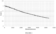
- the dopant profile of this example shows a monotonic decrease in fluorine content dropping from about 2.0% at the surface of the glass article to less than about 1.0% near the center of the glass article.
- the nonuniform dopant profile is believed to be a result of a progressively diffusion limited reaction. It is believed that the reaction of fluorine at 1145°C is sufficient to increase the densification rate at the outer surface of the glass article, and thereby limit diffusivity of the dopant beyond the outer surface of the glass article.
- a soot compact having a diameter of about 14 cm was heat treated in a furnace under a helium atmosphere.
- the soot compact was held isothermally at a temperature of about 1060°C for a period of about 4.0 hours.
- a gas flow having about 9.0% chlorine was flowed through the furnace to dry the soot compact of moisture and hydroxyl groups, and to remove any transition metal contaminants.
- a gas flow having about 25% silicon tetrafluoride (SiF 4 ) was then flowed through the furnace for a period of about 2.0 hours to dope the soot compact with fluorine.
- the furnace temperature was increased from about 1060°C to about 1300°C over a period of about 30 minutes under a gas flow of about 2.0% SiF 4 , and held for about 15 minutes.
- the soot compact was then sintered under a helium atmosphere at a temperature of about 1190°C for about 12 hours to form a doped glass article.
- the dopant profile of this example shows uniform fluorine content of about 0.80% from the center of the glass article to within about 7.0 mm from the outer surface of the glass article. At the outer surface of the glass article, the fluorine content rises to about 1.0%. It is believed that the lower temperatures of this example, as compared to Example 1, allowed for sufficient diffusivity of the dopant to improve the uniformity doped glass article.
- a soot compact having a diameter of about 14 cm was heat treated in a closed system under a helium atmosphere.
- the closed system included a sealed furnace.
- the soot compact was held isothermally at a temperature of about 1060°C for a period of about 4.0 hours.
- the system was filled with a gas having about 50% chlorine to dry the soot compact of moisture and hydroxyl groups, and to remove any transition metal contaminants. After about 20 minutes, the gas was evacuated from the system. Three cycles of filling for about 1.0 minute to about 2.0 minutes, holding for about 20 minutes, and evacuating for about 10 minutes were performed.
- the system was evacuated for about 10 minutes. While maintaining the system temperature at about 1060°C, the system was filled with a gas having about 100% silicon tetrafluoride (SiF 4 ) and the system remained closed for about 2.0 hours to dope the soot compact. Subsequently, a vacuum was pulled on the closed system and the system temperature was increased from about 1060°C to about 1350°C over a period of about 30 minutes and the soot compact was held at about 1350°C for about 60 minutes to sinter the soot compact and to form a doped glass article.
- SiF 4 silicon tetrafluoride
- the dopant profile of this example shows uniform fluorine content of about 1.90% from the center of the glass article to within about 7.0 mm. At the outer surface of the glass article, the fluorine content decreases to about 1.10%. It is believed that the lower temperatures used in Example 2, coupled with the closed system of this example, allowed for sufficient diffusivity of the dopant to improve the uniformity doped glass article.
- a soot compact was doped with fluorine to show the relationship of doping pressure and doping temperature to the dopant content of the doped glass article.
- a doping temperature of about 1100°C and a doping pressure of about 25 kPa were selected to form a doped glass article having a fluorine content of about 1.5 wt.%.
- a 140 gram soot compact was positioned in the center of a hot zone of a closed system.
- the closed system was a tube furnace formed form a 1220 mm (48 inch) long and 90 mm (3.5 inch) diameter alumina tube that was fitted with sealed end caps and a valve on each end of the tube and which had a 610 mm (24 inch) hot zone.
- a vacuum pump was coupled to the valve on one end of the tube furnace and a source of SiF 4 was coupled to the valve on the other end of the tube furnace.
- the tube furnace was also equipped with a vacuum gauge (a Baratron® Direct Pressure/Vacuum Capacitance Manometer commercially available from MKS Instruments, Inc. of Andover, MA) and the pressure in the system was monitored to confirm there was no leakage when the valves were closed. With the valves closed, pressure in the tube furnace was reduced to 2.0 kPa and maintained for a period of about 6.0 hours.
- V SiF4 STP (P dope *V tube )*(273/T dry ) where P dope is the predetermined target doping pressure, V tube is the volume of the tube furnace, and T dry is the drying temperature.
- the SiF 4 was absorbed on the surface of the soot compact and reacted with SiOH on the surface of the soot compact to form HF as a by-product in the closed system.
- the pressure in the tube furnace dropped as the absorption of SiF 4 was greater than the formation of HF.
- the tube furnace was evacuated and then the valves were closed. While maintaining the vacuum of less than 2.0 kPa, the temperature in the hot zone of the tube furnace was raised to a temperature of about 1100°C.
- a doping process was initiated by flowing SiF 4 into the tube furnace until a doping pressure of 0.25 kPa was reached.
- the pressure in the tube furnace dropped as SiF 4 was absorbed by the soot compact, and the target doping pressure was maintained by opening the valve coupled to the source of SiF 4 and flowing more SiF 4 into the tube furnace.
- the pressure in the tube furnace was maintained at between about 24 kPa and about 25 kPa throughout the doping process.
- the doping process continued until the pressure in the tube furnace stabilized.
- the temperature of the tube furnace was raised to a sintering temperature of about 1300°C to complete the formation of a dense glass article.
- the glass article was determined to have a fluorine content of about 1.5 wt.%.
- Example 4 A similar process as described in Example 4 was utilized to illustrate that a soot compact can be doped with high levels of chlorine with high doping efficiency.
- a doping temperature of about 1060°C and a doping pressure of about 101 kPa were selected to form a doped glass article having a chlorine content of greater than about 2.0 wt.%.
- the closed system was the same as the closed system of Example 4, except that the closed system includes a 90 mm (3.5 inch) diameter silica tube.
- the closed system was placed in fluid communication with a vaporizer including a stainless steel vessel containing SiCl 4 .
- the stainless steel vessel was immersed in an oil bath set at greater than about 57°C in order to supply pure SiCl 4 gas at a pressure of about 101 kPa.
- a supply of either pure nitrogen or a combination of 2.0 wt.% Cl 2 with a balance of nitrogen gas was fixtured outside the closed system.
- a 140 gram silica soot compact was positioned in the center of a hot zone of the closed system.
- the pressure in the tube furnace was reduced to 2.0 kPa and, while under vacuum, the temperature of the furnace was raised to a drying temperature of about 1060°C.
- the soot compact was dried by flowing about 1.0 slpm of 2.0 wt.% Cl 2 in nitrogen for about 30 minutes through the tube furnace, with both of the valves opened. After drying, the tube furnace was evacuated and then both the valves were closed. While maintaining the vacuum of less than 2.0 kPa, the temperature in the hot zone of the tube furnace was raised to a temperature of about 1060°C.
- the doping process was initiated by releasing the SiCl 4 at about 57°C to equilibrate into the system volume.
- the closed system includes a gas pressure of SiCl 4 that is in equilibrium with the liquid source at the normal boiling point of SiCl 4 , a pressure of 101 kPa was maintained during the doping process which was performed for about 30 minutes.
- the temperature of the furnace was raised to a sintering temperature of about 1400°C to complete the formation of a dense glass article. Using X-ray fluorescence, the glass article was determined to have a chlorine content of be about 2.2 wt.%.
- the SiCl 4 remaining in the closed system may be condensed back into the stainless steel vessel for re-use in subsequent processes.
- the furnace was allowed to cool while the stainless steel vessel was simultaneously cooled to 0°C in an ice bath. During this cooling period, SiCl 4 was transported back into the stainless steel vessel. The furnace was then purged of any residual low level gas using a scrubber. Performing a doping process in closed systems such as described herein was observed to utilize or conserve greater than about 90% of the dopant gas. While the doping efficiency described in this example relates to a doping process using chlorine, it should be understood that the increased doping efficiencies described herein also relate to doping processes using other dopant containing gases.
- Example 5 A similar process as described in Example 5 was utilized to illustrate doping a soot compact with even high levels of chlorine while maintaining high doping efficiency.
- a doping temperature of about 1060°C and a doping pressure of about 101 kPa were selected to form a doped glass article having a chlorine content of greater than about 2.0 wt.%.
- the closed system was the same as the closed system of Example 4, except that the closed system includes a 90 mm (3.5 inch) diameter silica tube.
- the closed system was placed in fluid communication with a vaporizer including a stainless steel vessel containing SiCl 4 .
- the stainless steel vessel was immersed in an oil bath set at greater than about 80°C in order to supply pure SiCl 4 gas at a pressure of about 180 kPa.
- a supply of either pure nitrogen or a combination of 2.0 wt.% Cl 2 with a balance of nitrogen gas was fixtured outside the closed system.
- a 140 gram silica soot compact was positioned in the center of a hot zone of the closed system.
- the pressure in the tube furnace was reduced to 2.0 kPa and, while under vacuum, the temperature of the furnace was raised to a drying temperature of about 1060°C.
- the soot compact was dried by flowing about 1.0 slpm of 2.0 wt.% Cl 2 in nitrogen for about 30 minutes through the tube furnace, with both of the valves opened. After drying, the tube furnace was evacuated and then both the valves were closed. While maintaining the vacuum of less than 2.0 kPa, the temperature in the hot zone of the tube furnace was raised to a temperature of about 1060°C.
- the doping process was initiated by releasing the SiCl 4 at about 80°C to equilibrate into the system volume.
- the closed system includes a gas pressure of SiCl 4 that is in equilibrium with the liquid source at the normal boiling point of SiCl 4 , a pressure of 180 kPa was maintained during the doping process which was performed for about 30 minutes.
- the temperature of the furnace was raised to a sintering temperature of about 1300°C to complete the formation of a dense glass article. Using X-ray fluorescence, the glass article was determined to have a chlorine content of be about 2.6 wt.%.
- performing the doping process at higher pressures enabled formation of a doped glass article with higher dopant content.
- Performing the doping process in a closed system such as described herein enabled achieving the higher dopant content.
Landscapes
- Chemical & Material Sciences (AREA)
- Engineering & Computer Science (AREA)
- Materials Engineering (AREA)
- Organic Chemistry (AREA)
- Manufacturing & Machinery (AREA)
- Chemical Kinetics & Catalysis (AREA)
- Physics & Mathematics (AREA)
- Thermal Sciences (AREA)
- Life Sciences & Earth Sciences (AREA)
- Geochemistry & Mineralogy (AREA)
- General Chemical & Material Sciences (AREA)
- General Life Sciences & Earth Sciences (AREA)
- Dispersion Chemistry (AREA)
- General Physics & Mathematics (AREA)
- Optics & Photonics (AREA)
- Glass Compositions (AREA)
- Glass Melting And Manufacturing (AREA)
- Manufacture, Treatment Of Glass Fibers (AREA)
Claims (11)
- Verfahren zur Bildung eines optischen Elements, wobei das Verfahren folgendes umfasst:Erzeugen von Rußpartikeln auf Silica-Basis unter Verwendung von chemischer Gasphasenabscheidung, wobei die Rußpartikel auf Silica-Basis eine durchschnittliche Partikelgröße zwischen 0,05 µm und 0,25 µm aufweisen;Bilden eines Rußpresslings aus den Rußpartikeln auf Silica-Basis; undDotieren des Rußpresslings mit einem Halogen in einem geschlossenen System durch Inkontaktbringen des Rußpresslings auf Silica-Basis mit einem halogenhaltigen Gas in dem geschlossenen System auf einer Temperatur zwischen 850 °C und 1.100 °C und einem Gesamtdruck zwischen 25 kPa (0,25 atm) und 91 kPa (0,9 atm), wobei das geschlossene System den Rußpressling einschließt, es verhindert, dass Gase in dem geschlossenen System aus dem geschlossenen System strömen, und es verhindert, dass Umgebungsluft in das geschlossene System strömt.
- Verfahren nach Anspruch 1, ferner umfassend das Konsolidieren des Rußpresslings in dem geschlossenen System, um einen Glasartikel zu bilden.
- Verfahren zur Bildung eines optischen Elements, wobei das Verfahren folgendes umfasst:Erzeugen von Rußpartikeln auf Silica-Basis unter Verwendung von chemischer Gasphasenabscheidung, wobei die Rußpartikel auf Silica-Basis eine durchschnittliche Partikelgröße zwischen 0,05 µm und 0,25 µm aufweisen;Bilden eines Rußpresslings aus den Rußpartikeln auf Silica-Basis; undDotieren des Rußpresslings mit einem Halogen in einem geschlossenen System durch Inkontaktbringen des Rußpresslings mit einem halogenhaltigen Gas in dem geschlossenen System auf einer Temperatur zwischen 850 °C und 1.100 °C und einem Gesamtdruck zwischen 25 kPa (0,25 atm) und 91 kPa (0,9 atm); undKonsolidieren des Rußpresslings in dem geschlossenen System, um einen Glasartikel zu bilden, durch gleichzeitiges Erhöhen der Temperatur in dem geschlossenen System und Reduzieren der Konzentration des halogenhaltigen Gases in dem geschlossenen System, wobei das geschlossene System den Rußpressling einschließt, es verhindert, dass Gase in dem geschlossenen System aus dem geschlossenen System strömen, und es verhindert, dass Umgebungsluft in das geschlossene System strömt.
- Verfahren nach Anspruch 3, wobei das Reduzieren der Konzentration des halogenhaltigen Gases in dem geschlossenen System das Reduzieren der Konzentration des halogenhaltigen Gases gemäß der folgenden Formel umfasst:
 wobei folgendes gilt: TI,dop ist die Temperatur in dem geschlossenen System, wenn der Rußpressling mit Halogen dotiert wird;TII ist die Temperatur in dem geschlossenen System, wenn der Rußpressling konsolidiert wird;yI,dop ist die Konzentration in Molanteilen des halogenhaltigen Gases in dem geschlossenen System, wenn der Rußpressling mit Halogen dotiert wird;yII ist die maximale Konzentration in Molanteilen des halogenhaltigen Gases in dem geschlossenen System, wenn der Rußpressling auf TII konsolidiert wird.
 - Verfahren nach einem der vorstehenden Ansprüche, wobei das Dotieren des Rußpresslings ferner das Erhalten einer vorbestimmten halogenhaltigen Gaszusammensetzung in dem geschlossenen System umfasst.
- Verfahren nach einem der vorstehenden Ansprüche, wobei das Dotieren des Rußpresslings ferner das Erhalten eines vorbestimmten halogenhaltigen Gasteildrucks in dem geschlossenen System umfasst.
- Verfahren nach einem der vorstehenden Ansprüche, wobei das halogenhaltige Gas ausgewählt ist aus der Gruppe bestehend aus einem fluorhaltigen Gas und einem chlorhaltigen Gas.
- Verfahren nach einem der vorstehenden Ansprüche, wobei das Bilden eines Rußpresslings das Abscheiden der Rußpartikel auf Silica-Basis auf einen Köderstab umfasst.
- Verfahren nach einem der Ansprüche 1 bis 7, wobei das Bilden des Rußpresslings das Pressen der Rußpartikel auf Silica-Basis mit einem Druck zwischen 690 kPa (100 psi) und 6.900 kPa (1.000 psi) umfasst.
- Verfahren nach einem der Ansprüche 2 bis 4, wobei das Konsolidieren des Rußpresslings ausreicht, um einen Glasartikel zu bilden, der eine Veränderung der Halogenkonzentration von weniger als 0,20 Gew.-% umfasst.
- Verfahren nach einem der vorstehenden Ansprüche, wobei die Rußpartikel auf Silica-Basis Silica und Titandioxid umfassen.
Priority Applications (1)
| Application Number | Priority Date | Filing Date | Title |
|---|---|---|---|
| EP21157711.9A EP3858795A1 (de) | 2014-11-26 | 2015-11-24 | Verfahren zur herstellung eines halogendotierten optischen elements |
Applications Claiming Priority (2)
| Application Number | Priority Date | Filing Date | Title |
|---|---|---|---|
| US201462084846P | 2014-11-26 | 2014-11-26 | |
| PCT/US2015/062472 WO2016086013A1 (en) | 2014-11-26 | 2015-11-24 | Method for making halogen doped optical element |
Related Child Applications (2)
| Application Number | Title | Priority Date | Filing Date |
|---|---|---|---|
| EP21157711.9A Division EP3858795A1 (de) | 2014-11-26 | 2015-11-24 | Verfahren zur herstellung eines halogendotierten optischen elements |
| EP21157711.9A Division-Into EP3858795A1 (de) | 2014-11-26 | 2015-11-24 | Verfahren zur herstellung eines halogendotierten optischen elements |
Publications (2)
| Publication Number | Publication Date |
|---|---|
| EP3224211A1 EP3224211A1 (de) | 2017-10-04 |
| EP3224211B1 true EP3224211B1 (de) | 2021-05-05 |
Family
ID=54782870
Family Applications (2)
| Application Number | Title | Priority Date | Filing Date |
|---|---|---|---|
| EP15805070.8A Active EP3224211B1 (de) | 2014-11-26 | 2015-11-24 | Verfahren zur herstellung eines mit halogen dotierten optischen elements |
| EP21157711.9A Withdrawn EP3858795A1 (de) | 2014-11-26 | 2015-11-24 | Verfahren zur herstellung eines halogendotierten optischen elements |
Family Applications After (1)
| Application Number | Title | Priority Date | Filing Date |
|---|---|---|---|
| EP21157711.9A Withdrawn EP3858795A1 (de) | 2014-11-26 | 2015-11-24 | Verfahren zur herstellung eines halogendotierten optischen elements |
Country Status (4)
| Country | Link |
|---|---|
| US (2) | US20170362115A1 (de) |
| EP (2) | EP3224211B1 (de) |
| JP (1) | JP6748644B2 (de) |
| WO (1) | WO2016086013A1 (de) |
Families Citing this family (14)
| Publication number | Priority date | Publication date | Assignee | Title |
|---|---|---|---|---|
| US9822030B2 (en) * | 2015-02-13 | 2017-11-21 | Corning Incorporated | Ultralow expansion titania-silica glass |
| US9932261B2 (en) * | 2015-11-23 | 2018-04-03 | Corning Incorporated | Doped ultra-low expansion glass and methods for annealing the same |
| RU2736023C2 (ru) * | 2015-12-22 | 2020-11-11 | Корнинг Инкорпорейтед | Легированное бромом оптическое волокно |
| EP3473603B1 (de) * | 2017-10-20 | 2023-08-30 | Corning Incorporated | Herstellungsverfahren für mit halogen dotierter kieselsäure |
| NL2019876B1 (en) | 2017-10-20 | 2019-04-29 | Corning Inc | Optical fiber preforms with halogen doping |
| US10947149B2 (en) * | 2017-10-30 | 2021-03-16 | Corning Incorporated | Halogen-doped silica for optical fiber preforms |
| US10571628B2 (en) | 2017-11-20 | 2020-02-25 | Corning Incorporated | Low loss optical fiber with core codoped with two or more halogens |
| CN112203991A (zh) * | 2018-05-22 | 2021-01-08 | 住友电气工业株式会社 | 玻璃母材的制造方法 |
| US11175450B2 (en) * | 2018-08-08 | 2021-11-16 | Corning Incorporated | Halogen co-doped optical fibers |
| IT201800009920A1 (it) * | 2018-10-30 | 2020-04-30 | Prysmian Spa | Metodo per fabbricare una preforma di vetro per fibre ottiche |
| CN116234778A (zh) * | 2020-09-28 | 2023-06-06 | 住友电气工业株式会社 | 含氟石英玻璃的制造方法 |
| CN114634311B (zh) * | 2022-03-28 | 2023-04-11 | 中国科学院上海光学精密机械研究所 | 一种提高铋掺杂石英玻璃的近红外荧光强度的方法 |
| JP2024003583A (ja) * | 2022-06-27 | 2024-01-15 | 住友電気工業株式会社 | ガラス母材の製造装置およびガラス母材の製造方法 |
| WO2025014860A1 (en) * | 2023-07-11 | 2025-01-16 | Corning Incorporated | Titania-silica glass body with high quality polishing characteristics |
Family Cites Families (17)
| Publication number | Priority date | Publication date | Assignee | Title |
|---|---|---|---|---|
| EP0542724B1 (de) * | 1987-02-16 | 1996-06-12 | Sumitomo Electric Industries Limited | Ofen zum Erhitzen einer Glasvorform für optische Faser und Verfahren zum Herstellen einer Glasvorform |
| JPS6476927A (en) * | 1987-02-16 | 1989-03-23 | Sumitomo Electric Industries | Heating oven for optical fiber parent glass and its production |
| US5200173A (en) * | 1989-08-30 | 1993-04-06 | Revlon Consumer Products Corporation | Molded cosmetic products containing uniform ultra glossy wet look surface finish |
| JP3175247B2 (ja) * | 1991-12-16 | 2001-06-11 | 住友電気工業株式会社 | 光ファイバ用多孔質母材の加熱透明化方法 |
| WO1998000372A2 (en) * | 1996-06-17 | 1998-01-08 | Corning Incorporated | Process for forming a titania-containing preform silica glass blank |
| US8037717B2 (en) * | 2001-10-26 | 2011-10-18 | Corning Incorporated | Methods and apparatus for pulsed doping or drying a soot preform |
| US20030221459A1 (en) * | 2002-05-31 | 2003-12-04 | Walczak Wanda J. | Method for forming an optical waveguide fiber preform |
| JP2004131373A (ja) * | 2002-09-09 | 2004-04-30 | Corning Inc | シリカ・チタニア極端紫外線光学素子の製造方法 |
| JP4792706B2 (ja) * | 2003-04-03 | 2011-10-12 | 旭硝子株式会社 | TiO2を含有するシリカガラスおよびその製造方法 |
| US20060130529A1 (en) * | 2004-12-20 | 2006-06-22 | Bookbinder Dana C | Methods and apparatus for processing soot articles |
| KR20100118125A (ko) * | 2008-02-29 | 2010-11-04 | 아사히 가라스 가부시키가이샤 | TiO₂ 함유 실리카 유리 및 이를 사용한 리소그래피용 광학 부재 |
| EP2377826B2 (de) * | 2009-01-13 | 2020-05-27 | AGC Inc. | OPTISCHES ELEMENT MIT TiO2-HALTIGEM QUARZGLAS |
| US8468852B2 (en) * | 2009-12-03 | 2013-06-25 | Corning Incorporated | Soot pressing for optical fiber overcladding |
| JP2011225438A (ja) * | 2010-04-01 | 2011-11-10 | Asahi Glass Co Ltd | 合成石英ガラスの製造方法 |
| US8901019B2 (en) * | 2012-11-30 | 2014-12-02 | Corning Incorporated | Very low CTE slope doped silica-titania glass |
| DE102013101328B3 (de) * | 2013-02-11 | 2014-02-13 | Heraeus Quarzglas Gmbh & Co. Kg | Rohling aus TiO2-SiO2-Glas für ein Spiegelsubstrat für den Einsatz in der EUV-Lithographie sowie Verfahren für dessen Herstellung |
| EP3000791B1 (de) * | 2014-09-24 | 2017-04-26 | Heraeus Quarzglas GmbH & Co. KG | Verfahren zur Herstellung eines Rohlings aus Fluor- und Titan-dotiertem, hochkieselsäurehaltigem Glas für den Einsatz in der EUV-Lithographie und danach hergestellter Rohling |
-
2015
- 2015-11-24 EP EP15805070.8A patent/EP3224211B1/de active Active
- 2015-11-24 WO PCT/US2015/062472 patent/WO2016086013A1/en not_active Ceased
- 2015-11-24 US US15/529,583 patent/US20170362115A1/en not_active Abandoned
- 2015-11-24 JP JP2017527892A patent/JP6748644B2/ja active Active
- 2015-11-24 EP EP21157711.9A patent/EP3858795A1/de not_active Withdrawn
-
2023
- 2023-10-06 US US18/377,484 patent/US20240034667A1/en active Pending
Also Published As
| Publication number | Publication date |
|---|---|
| WO2016086013A1 (en) | 2016-06-02 |
| JP2017536324A (ja) | 2017-12-07 |
| EP3224211A1 (de) | 2017-10-04 |
| JP6748644B2 (ja) | 2020-09-02 |
| US20170362115A1 (en) | 2017-12-21 |
| EP3858795A1 (de) | 2021-08-04 |
| US20240034667A1 (en) | 2024-02-01 |
Similar Documents
| Publication | Publication Date | Title |
|---|---|---|
| US20240034667A1 (en) | Method for making halogen doped optical element | |
| US3933454A (en) | Method of making optical waveguides | |
| RU2736023C2 (ru) | Легированное бромом оптическое волокно | |
| JP5202959B2 (ja) | 高屈折率均一性溶融シリカガラスおよびその製造方法 | |
| TWI651277B (zh) | 製造用於euv微影術之高矽酸含量的氟與鈦摻雜玻璃底板的方法及由該方法製造之底板 | |
| WO2010082586A1 (ja) | TiO2を含有するシリカガラスからなる光学部材 | |
| JP2016531828A (ja) | Euvリソグラフィーに使用されるチタンドープシリカガラスを作製する方法及びそれに従って作製されるブランク | |
| TWI689476B (zh) | 摻雜的超低膨脹玻璃及用於製造其之方法 | |
| US7125912B2 (en) | Doped sol-gel materials and method of manufacture utilizing reduced mixing temperatures | |
| US7001568B2 (en) | Method of removing liquid from pores of a sol-gel monolith | |
| US6928220B2 (en) | Sol-gel-derived optical fiber preform and method of manufacture | |
| US20030147606A1 (en) | Sol-gel-based optical preforms and methods of manufacture | |
| CN112805252B (zh) | 用于光纤的卤素掺杂二氧化硅预制件的制造方法 | |
| EP3473603B1 (de) | Herstellungsverfahren für mit halogen dotierter kieselsäure | |
| US7000885B2 (en) | Apparatus and method for forming a sol-gel monolith utilizing multiple casting | |
| JP3274955B2 (ja) | 紫外領域用途の光学部品用合成石英ガラス母材の製造方法、及び合成石英ガラス材の製造方法 | |
| WO2006068853A1 (en) | Methods and apparatus for processing soot articles | |
| CN114735927A (zh) | 一种生产半导体掩模版用合成石英材料的方法 | |
| CN111315696A (zh) | 用于光纤预制件的卤素掺杂的二氧化硅 | |
| JP2004345903A (ja) | 石英ガラスの製造方法、石英ガラス、光学部品及び光ファイバ | |
| JP2024141315A (ja) | シリカガラスの製造方法、及び光ファイバの製造方法 | |
| JP2004345902A (ja) | 石英ガラスの製造方法、石英ガラス、光学部品及び光ファイバ | |
| JP4162952B2 (ja) | 合成石英ガラスの製造方法および多孔質石英ガラス製造装置 |
Legal Events
| Date | Code | Title | Description |
|---|---|---|---|
| STAA | Information on the status of an ep patent application or granted ep patent |
Free format text: STATUS: THE INTERNATIONAL PUBLICATION HAS BEEN MADE |
|
| PUAI | Public reference made under article 153(3) epc to a published international application that has entered the european phase |
Free format text: ORIGINAL CODE: 0009012 |
|
| STAA | Information on the status of an ep patent application or granted ep patent |
Free format text: STATUS: REQUEST FOR EXAMINATION WAS MADE |
|
| 17P | Request for examination filed |
Effective date: 20170608 |
|
| AK | Designated contracting states |
Kind code of ref document: A1 Designated state(s): AL AT BE BG CH CY CZ DE DK EE ES FI FR GB GR HR HU IE IS IT LI LT LU LV MC MK MT NL NO PL PT RO RS SE SI SK SM TR |
|
| AX | Request for extension of the european patent |
Extension state: BA ME |
|
| DAV | Request for validation of the european patent (deleted) | ||
| DAX | Request for extension of the european patent (deleted) | ||
| STAA | Information on the status of an ep patent application or granted ep patent |
Free format text: STATUS: EXAMINATION IS IN PROGRESS |
|
| 17Q | First examination report despatched |
Effective date: 20180329 |
|
| GRAP | Despatch of communication of intention to grant a patent |
Free format text: ORIGINAL CODE: EPIDOSNIGR1 |
|
| STAA | Information on the status of an ep patent application or granted ep patent |
Free format text: STATUS: GRANT OF PATENT IS INTENDED |
|
| INTG | Intention to grant announced |
Effective date: 20201118 |
|
| GRAS | Grant fee paid |
Free format text: ORIGINAL CODE: EPIDOSNIGR3 |
|
| GRAA | (expected) grant |
Free format text: ORIGINAL CODE: 0009210 |
|
| STAA | Information on the status of an ep patent application or granted ep patent |
Free format text: STATUS: THE PATENT HAS BEEN GRANTED |
|
| AK | Designated contracting states |
Kind code of ref document: B1 Designated state(s): AL AT BE BG CH CY CZ DE DK EE ES FI FR GB GR HR HU IE IS IT LI LT LU LV MC MK MT NL NO PL PT RO RS SE SI SK SM TR |
|
| REG | Reference to a national code |
Ref country code: GB Ref legal event code: FG4D |
|
| REG | Reference to a national code |
Ref country code: CH Ref legal event code: EP |
|
| REG | Reference to a national code |
Ref country code: AT Ref legal event code: REF Ref document number: 1389629 Country of ref document: AT Kind code of ref document: T Effective date: 20210515 |
|
| REG | Reference to a national code |
Ref country code: IE Ref legal event code: FG4D |
|
| REG | Reference to a national code |
Ref country code: DE Ref legal event code: R096 Ref document number: 602015069045 Country of ref document: DE |
|
| REG | Reference to a national code |
Ref country code: LT Ref legal event code: MG9D |
|
| REG | Reference to a national code |
Ref country code: AT Ref legal event code: MK05 Ref document number: 1389629 Country of ref document: AT Kind code of ref document: T Effective date: 20210505 |
|
| PG25 | Lapsed in a contracting state [announced via postgrant information from national office to epo] |
Ref country code: LT Free format text: LAPSE BECAUSE OF FAILURE TO SUBMIT A TRANSLATION OF THE DESCRIPTION OR TO PAY THE FEE WITHIN THE PRESCRIBED TIME-LIMIT Effective date: 20210505 Ref country code: FI Free format text: LAPSE BECAUSE OF FAILURE TO SUBMIT A TRANSLATION OF THE DESCRIPTION OR TO PAY THE FEE WITHIN THE PRESCRIBED TIME-LIMIT Effective date: 20210505 Ref country code: AT Free format text: LAPSE BECAUSE OF FAILURE TO SUBMIT A TRANSLATION OF THE DESCRIPTION OR TO PAY THE FEE WITHIN THE PRESCRIBED TIME-LIMIT Effective date: 20210505 Ref country code: BG Free format text: LAPSE BECAUSE OF FAILURE TO SUBMIT A TRANSLATION OF THE DESCRIPTION OR TO PAY THE FEE WITHIN THE PRESCRIBED TIME-LIMIT Effective date: 20210805 Ref country code: HR Free format text: LAPSE BECAUSE OF FAILURE TO SUBMIT A TRANSLATION OF THE DESCRIPTION OR TO PAY THE FEE WITHIN THE PRESCRIBED TIME-LIMIT Effective date: 20210505 |
|
| PG25 | Lapsed in a contracting state [announced via postgrant information from national office to epo] |
Ref country code: RS Free format text: LAPSE BECAUSE OF FAILURE TO SUBMIT A TRANSLATION OF THE DESCRIPTION OR TO PAY THE FEE WITHIN THE PRESCRIBED TIME-LIMIT Effective date: 20210505 Ref country code: SE Free format text: LAPSE BECAUSE OF FAILURE TO SUBMIT A TRANSLATION OF THE DESCRIPTION OR TO PAY THE FEE WITHIN THE PRESCRIBED TIME-LIMIT Effective date: 20210505 Ref country code: PT Free format text: LAPSE BECAUSE OF FAILURE TO SUBMIT A TRANSLATION OF THE DESCRIPTION OR TO PAY THE FEE WITHIN THE PRESCRIBED TIME-LIMIT Effective date: 20210906 Ref country code: PL Free format text: LAPSE BECAUSE OF FAILURE TO SUBMIT A TRANSLATION OF THE DESCRIPTION OR TO PAY THE FEE WITHIN THE PRESCRIBED TIME-LIMIT Effective date: 20210505 Ref country code: NO Free format text: LAPSE BECAUSE OF FAILURE TO SUBMIT A TRANSLATION OF THE DESCRIPTION OR TO PAY THE FEE WITHIN THE PRESCRIBED TIME-LIMIT Effective date: 20210805 Ref country code: GR Free format text: LAPSE BECAUSE OF FAILURE TO SUBMIT A TRANSLATION OF THE DESCRIPTION OR TO PAY THE FEE WITHIN THE PRESCRIBED TIME-LIMIT Effective date: 20210806 Ref country code: IS Free format text: LAPSE BECAUSE OF FAILURE TO SUBMIT A TRANSLATION OF THE DESCRIPTION OR TO PAY THE FEE WITHIN THE PRESCRIBED TIME-LIMIT Effective date: 20210905 Ref country code: LV Free format text: LAPSE BECAUSE OF FAILURE TO SUBMIT A TRANSLATION OF THE DESCRIPTION OR TO PAY THE FEE WITHIN THE PRESCRIBED TIME-LIMIT Effective date: 20210505 |
|
| REG | Reference to a national code |
Ref country code: NL Ref legal event code: MP Effective date: 20210505 |
|
| PG25 | Lapsed in a contracting state [announced via postgrant information from national office to epo] |
Ref country code: NL Free format text: LAPSE BECAUSE OF FAILURE TO SUBMIT A TRANSLATION OF THE DESCRIPTION OR TO PAY THE FEE WITHIN THE PRESCRIBED TIME-LIMIT Effective date: 20210505 |
|
| PG25 | Lapsed in a contracting state [announced via postgrant information from national office to epo] |
Ref country code: RO Free format text: LAPSE BECAUSE OF FAILURE TO SUBMIT A TRANSLATION OF THE DESCRIPTION OR TO PAY THE FEE WITHIN THE PRESCRIBED TIME-LIMIT Effective date: 20210505 Ref country code: ES Free format text: LAPSE BECAUSE OF FAILURE TO SUBMIT A TRANSLATION OF THE DESCRIPTION OR TO PAY THE FEE WITHIN THE PRESCRIBED TIME-LIMIT Effective date: 20210505 Ref country code: SM Free format text: LAPSE BECAUSE OF FAILURE TO SUBMIT A TRANSLATION OF THE DESCRIPTION OR TO PAY THE FEE WITHIN THE PRESCRIBED TIME-LIMIT Effective date: 20210505 Ref country code: SK Free format text: LAPSE BECAUSE OF FAILURE TO SUBMIT A TRANSLATION OF THE DESCRIPTION OR TO PAY THE FEE WITHIN THE PRESCRIBED TIME-LIMIT Effective date: 20210505 Ref country code: EE Free format text: LAPSE BECAUSE OF FAILURE TO SUBMIT A TRANSLATION OF THE DESCRIPTION OR TO PAY THE FEE WITHIN THE PRESCRIBED TIME-LIMIT Effective date: 20210505 Ref country code: DK Free format text: LAPSE BECAUSE OF FAILURE TO SUBMIT A TRANSLATION OF THE DESCRIPTION OR TO PAY THE FEE WITHIN THE PRESCRIBED TIME-LIMIT Effective date: 20210505 Ref country code: CZ Free format text: LAPSE BECAUSE OF FAILURE TO SUBMIT A TRANSLATION OF THE DESCRIPTION OR TO PAY THE FEE WITHIN THE PRESCRIBED TIME-LIMIT Effective date: 20210505 |
|
| REG | Reference to a national code |
Ref country code: DE Ref legal event code: R097 Ref document number: 602015069045 Country of ref document: DE |
|
| PLBE | No opposition filed within time limit |
Free format text: ORIGINAL CODE: 0009261 |
|
| STAA | Information on the status of an ep patent application or granted ep patent |
Free format text: STATUS: NO OPPOSITION FILED WITHIN TIME LIMIT |
|
| 26N | No opposition filed |
Effective date: 20220208 |
|
| PG25 | Lapsed in a contracting state [announced via postgrant information from national office to epo] |
Ref country code: IS Free format text: LAPSE BECAUSE OF FAILURE TO SUBMIT A TRANSLATION OF THE DESCRIPTION OR TO PAY THE FEE WITHIN THE PRESCRIBED TIME-LIMIT Effective date: 20210905 Ref country code: AL Free format text: LAPSE BECAUSE OF FAILURE TO SUBMIT A TRANSLATION OF THE DESCRIPTION OR TO PAY THE FEE WITHIN THE PRESCRIBED TIME-LIMIT Effective date: 20210505 |
|
| PG25 | Lapsed in a contracting state [announced via postgrant information from national office to epo] |
Ref country code: MC Free format text: LAPSE BECAUSE OF FAILURE TO SUBMIT A TRANSLATION OF THE DESCRIPTION OR TO PAY THE FEE WITHIN THE PRESCRIBED TIME-LIMIT Effective date: 20210505 |
|
| REG | Reference to a national code |
Ref country code: CH Ref legal event code: PL |
|
| PG25 | Lapsed in a contracting state [announced via postgrant information from national office to epo] |
Ref country code: LU Free format text: LAPSE BECAUSE OF NON-PAYMENT OF DUE FEES Effective date: 20211124 Ref country code: IT Free format text: LAPSE BECAUSE OF FAILURE TO SUBMIT A TRANSLATION OF THE DESCRIPTION OR TO PAY THE FEE WITHIN THE PRESCRIBED TIME-LIMIT Effective date: 20210505 Ref country code: BE Free format text: LAPSE BECAUSE OF NON-PAYMENT OF DUE FEES Effective date: 20211130 |
|
| REG | Reference to a national code |
Ref country code: BE Ref legal event code: MM Effective date: 20211130 |
|
| PG25 | Lapsed in a contracting state [announced via postgrant information from national office to epo] |
Ref country code: LI Free format text: LAPSE BECAUSE OF NON-PAYMENT OF DUE FEES Effective date: 20211130 Ref country code: CH Free format text: LAPSE BECAUSE OF NON-PAYMENT OF DUE FEES Effective date: 20211130 |
|
| PG25 | Lapsed in a contracting state [announced via postgrant information from national office to epo] |
Ref country code: IE Free format text: LAPSE BECAUSE OF NON-PAYMENT OF DUE FEES Effective date: 20211124 |
|
| PG25 | Lapsed in a contracting state [announced via postgrant information from national office to epo] |
Ref country code: FR Free format text: LAPSE BECAUSE OF NON-PAYMENT OF DUE FEES Effective date: 20211130 |
|
| PG25 | Lapsed in a contracting state [announced via postgrant information from national office to epo] |
Ref country code: HU Free format text: LAPSE BECAUSE OF FAILURE TO SUBMIT A TRANSLATION OF THE DESCRIPTION OR TO PAY THE FEE WITHIN THE PRESCRIBED TIME-LIMIT; INVALID AB INITIO Effective date: 20151124 |
|
| PG25 | Lapsed in a contracting state [announced via postgrant information from national office to epo] |
Ref country code: CY Free format text: LAPSE BECAUSE OF FAILURE TO SUBMIT A TRANSLATION OF THE DESCRIPTION OR TO PAY THE FEE WITHIN THE PRESCRIBED TIME-LIMIT Effective date: 20210505 |
|
| PG25 | Lapsed in a contracting state [announced via postgrant information from national office to epo] |
Ref country code: MK Free format text: LAPSE BECAUSE OF FAILURE TO SUBMIT A TRANSLATION OF THE DESCRIPTION OR TO PAY THE FEE WITHIN THE PRESCRIBED TIME-LIMIT Effective date: 20210505 |
|
| PG25 | Lapsed in a contracting state [announced via postgrant information from national office to epo] |
Ref country code: TR Free format text: LAPSE BECAUSE OF FAILURE TO SUBMIT A TRANSLATION OF THE DESCRIPTION OR TO PAY THE FEE WITHIN THE PRESCRIBED TIME-LIMIT Effective date: 20210505 |
|
| PG25 | Lapsed in a contracting state [announced via postgrant information from national office to epo] |
Ref country code: MT Free format text: LAPSE BECAUSE OF FAILURE TO SUBMIT A TRANSLATION OF THE DESCRIPTION OR TO PAY THE FEE WITHIN THE PRESCRIBED TIME-LIMIT Effective date: 20210505 |
|
| PGFP | Annual fee paid to national office [announced via postgrant information from national office to epo] |
Ref country code: DE Payment date: 20251013 Year of fee payment: 11 |
|
| PGFP | Annual fee paid to national office [announced via postgrant information from national office to epo] |
Ref country code: GB Payment date: 20251009 Year of fee payment: 11 |