EP3224859B1 - Verfahren und vorrichtung zur unterseitigen behandlung eines substrats - Google Patents
Verfahren und vorrichtung zur unterseitigen behandlung eines substrats Download PDFInfo
- Publication number
- EP3224859B1 EP3224859B1 EP15830976.5A EP15830976A EP3224859B1 EP 3224859 B1 EP3224859 B1 EP 3224859B1 EP 15830976 A EP15830976 A EP 15830976A EP 3224859 B1 EP3224859 B1 EP 3224859B1
- Authority
- EP
- European Patent Office
- Prior art keywords
- substrate
- liquid
- protective liquid
- rinsing
- substrates
- Prior art date
- Legal status (The legal status is an assumption and is not a legal conclusion. Google has not performed a legal analysis and makes no representation as to the accuracy of the status listed.)
- Active
Links
Images
Classifications
-
- H—ELECTRICITY
- H10—SEMICONDUCTOR DEVICES; ELECTRIC SOLID-STATE DEVICES NOT OTHERWISE PROVIDED FOR
- H10P—GENERIC PROCESSES OR APPARATUS FOR THE MANUFACTURE OR TREATMENT OF DEVICES COVERED BY CLASS H10
- H10P72/00—Handling or holding of wafers, substrates or devices during manufacture or treatment thereof
- H10P72/30—Handling or holding of wafers, substrates or devices during manufacture or treatment thereof for conveying, e.g. between different workstations
- H10P72/32—Handling or holding of wafers, substrates or devices during manufacture or treatment thereof for conveying, e.g. between different workstations between different workstations
- H10P72/3202—Mechanical details, e.g. rollers or belts
-
- H—ELECTRICITY
- H10—SEMICONDUCTOR DEVICES; ELECTRIC SOLID-STATE DEVICES NOT OTHERWISE PROVIDED FOR
- H10F—INORGANIC SEMICONDUCTOR DEVICES SENSITIVE TO INFRARED RADIATION, LIGHT, ELECTROMAGNETIC RADIATION OF SHORTER WAVELENGTH OR CORPUSCULAR RADIATION
- H10F71/00—Manufacture or treatment of devices covered by this subclass
- H10F71/121—The active layers comprising only Group IV materials
-
- H—ELECTRICITY
- H10—SEMICONDUCTOR DEVICES; ELECTRIC SOLID-STATE DEVICES NOT OTHERWISE PROVIDED FOR
- H10P—GENERIC PROCESSES OR APPARATUS FOR THE MANUFACTURE OR TREATMENT OF DEVICES COVERED BY CLASS H10
- H10P50/00—Etching of wafers, substrates or parts of devices
-
- H—ELECTRICITY
- H10—SEMICONDUCTOR DEVICES; ELECTRIC SOLID-STATE DEVICES NOT OTHERWISE PROVIDED FOR
- H10P—GENERIC PROCESSES OR APPARATUS FOR THE MANUFACTURE OR TREATMENT OF DEVICES COVERED BY CLASS H10
- H10P72/00—Handling or holding of wafers, substrates or devices during manufacture or treatment thereof
- H10P72/04—Apparatus for manufacture or treatment
- H10P72/0402—Apparatus for fluid treatment
- H10P72/0406—Apparatus for fluid treatment for cleaning followed by drying, rinsing, stripping, blasting or the like
- H10P72/0411—Apparatus for fluid treatment for cleaning followed by drying, rinsing, stripping, blasting or the like for wet cleaning or washing
- H10P72/0416—Apparatus for fluid treatment for cleaning followed by drying, rinsing, stripping, blasting or the like for wet cleaning or washing with the semiconductor substrates being dipped in baths or vessels
-
- H—ELECTRICITY
- H10—SEMICONDUCTOR DEVICES; ELECTRIC SOLID-STATE DEVICES NOT OTHERWISE PROVIDED FOR
- H10P—GENERIC PROCESSES OR APPARATUS FOR THE MANUFACTURE OR TREATMENT OF DEVICES COVERED BY CLASS H10
- H10P72/00—Handling or holding of wafers, substrates or devices during manufacture or treatment thereof
- H10P72/04—Apparatus for manufacture or treatment
- H10P72/0402—Apparatus for fluid treatment
- H10P72/0418—Apparatus for fluid treatment for etching
- H10P72/0422—Apparatus for fluid treatment for etching for wet etching
- H10P72/0426—Apparatus for fluid treatment for etching for wet etching with the semiconductor substrates being dipped in baths or vessels
-
- H—ELECTRICITY
- H10—SEMICONDUCTOR DEVICES; ELECTRIC SOLID-STATE DEVICES NOT OTHERWISE PROVIDED FOR
- H10P—GENERIC PROCESSES OR APPARATUS FOR THE MANUFACTURE OR TREATMENT OF DEVICES COVERED BY CLASS H10
- H10P72/00—Handling or holding of wafers, substrates or devices during manufacture or treatment thereof
- H10P72/30—Handling or holding of wafers, substrates or devices during manufacture or treatment thereof for conveying, e.g. between different workstations
- H10P72/33—Handling or holding of wafers, substrates or devices during manufacture or treatment thereof for conveying, e.g. between different workstations into and out of processing chamber
- H10P72/3314—Continuous loading and unloading into and out of a processing chamber, e.g. transporting belts within processing chambers
-
- Y—GENERAL TAGGING OF NEW TECHNOLOGICAL DEVELOPMENTS; GENERAL TAGGING OF CROSS-SECTIONAL TECHNOLOGIES SPANNING OVER SEVERAL SECTIONS OF THE IPC; TECHNICAL SUBJECTS COVERED BY FORMER USPC CROSS-REFERENCE ART COLLECTIONS [XRACs] AND DIGESTS
- Y02—TECHNOLOGIES OR APPLICATIONS FOR MITIGATION OR ADAPTATION AGAINST CLIMATE CHANGE
- Y02P—CLIMATE CHANGE MITIGATION TECHNOLOGIES IN THE PRODUCTION OR PROCESSING OF GOODS
- Y02P70/00—Climate change mitigation technologies in the production process for final industrial or consumer products
- Y02P70/50—Manufacturing or production processes characterised by the final manufactured product
Definitions
- the invention relates to a method for treating the underside of a flat substrate and a device for carrying out the method according to the claim.
- a method for treating the underside of a flat substrate in the field of manufacturing semiconductor components it is sometimes necessary to treat flat substrates on one side. Often an underside of the substrate is treated for this purpose.
- WO 2011/047894 A1 It is known to spray, splash, drip or apply a protective liquid to the top of the substrate to protect it.
- a protective liquid can be applied to the top before the substrate is wetted with the treatment liquid on the underside. In this way, the amount of protective liquid introduced into the treatment liquid can be reduced.
- WO 2011/047894 A1 As already explained, even then, dripping of protective liquid into the treatment medium or the treatment liquid cannot be prevented. If water is used as a protective liquid, this results in a dilution of the treatment liquid and thus an increased consumption of chemicals In addition, increased process effort is required to ensure constant treatment conditions, such as a constant composition of the treatment liquid, and thus process reliability. If a different material is used as the treatment liquid, this usually leads to contamination of the treatment medium with similar and usually even more complex to control consequences.
- an inhomogeneous appearance of the underside of the substrate results and thus, in addition to possible electrical impairments of the semiconductor component, an inhomogeneous appearance of the finished solar cell.
- problems can arise in subsequent process steps. For example, an inhomogeneous thickness of an oxide layer arranged on the underside of the substrate can lead to a subsequent etching step carried out on the underside of the substrate starting at different times.
- the known procedure involves the risk that a treatment liquid used as a treatment medium that wets the underside of the substrate will creep over the edges of the substrate as a result of a concentration gradient or due to wetting phenomena and thus reach the top of the substrate. There it can damage the surface of the substrate locally or over the entire area, for example as a result of an etching effect.
- the present invention is based on the object of providing a method for treating the underside of a flat substrate, by means of which at least some of the disadvantages described can be overcome in a cost-effective manner.
- the present invention is based on the object of providing a device by means of which this method can be carried out and the risk of damage to the upper side of the substrate can be further reduced.
- the method according to the invention provides that, for the purpose of treating the underside of a flat substrate with a treatment medium, firstly an underside of the substrate is hydrophobized by means of one-sided, wet-chemical etching. Subsequently, an upper side of the substrate a protective liquid film is formed. The treatment medium is then brought into contact with the underside of the substrate and the upper side is protected by the protective liquid film against the effects of the treatment medium and/or its outgassing.
- the hydrophobic treatment can save a drying step in many applications, which would be necessary before a further process step in previously known processes. Furthermore, the process can be designed as a continuous process and can be easily integrated into existing continuous systems.
- Hydrophobization within the meaning of the present invention is achieved when the protective liquid wets the hydrophobized surface with a contact angle greater than 60°.
- the upper side can be protected against the treatment medium itself, which can be in the form of a liquid or gas or gas mixture.
- the protective liquid film is preferably used both as protection against treatment liquid reaching the upper side and as protection against outgassing from the treatment liquid reaching the upper side of the substrate. Such outgassing can occur, for example, through partial evaporation of the treatment liquid.
- Water is preferably used as the protective liquid, particularly deionized water. This has proven itself in many applications and can usually be treated or disposed of relatively easily.
- a silicon substrate is treated and a silicate glass layer, for example a phosphor or borosilicate glass layer, is removed from the underside of the silicon substrate in order to make the underside of this silicon substrate hydrophobic.
- a silicate glass layer for example a phosphor or borosilicate glass layer
- Such silicate glass layers are frequently used in the manufacture of semiconductor components, in particular in the manufacture of silicon solar cells, so that this enables a particularly cost-effective process.
- proven techniques can be used to make the silicon substrate hydrophobic.
- a protective liquid is applied to the top of the substrate using an application device for the purpose of forming the protective liquid film.
- application devices such as spray nozzles can be used as the application device.
- at least one surge pipe is used as the application device.
- An alternative embodiment provides for the substrate to be immersed in the protective liquid for the purpose of forming the protective liquid film and to be removed from it.
- the substrate When removing the substrate from the protective liquid, the substrate is aligned in such a way that it extends in a substantially horizontal plane, so that the desired protective liquid film remains on the top side of the substrate.
- the fact that the substrate is aligned when removed from the protective liquid so that it extends in a substantially horizontal plane is to be understood in the sense that slight deviations from the horizontal are possible for a short time. How long the deviation from the horizontal can be and to what exact extent depends on the properties of the materials used, in particular the viscosity of the protective liquid and the adhesion forces between the top side of the substrate and the protective liquid.
- the edges of the substrate are also hydrophobized, preferably completely.
- This is advantageously done in a joint process step with the hydrophobization of the underside of the substrate.
- This means that the underside and the edges of the substrate are hydrophobized simultaneously in a single process step.
- the underside of the substrate can advantageously be hydrophobized using one-sided, wet-chemical etching.
- One-sided in this context means that no etching solution used for wet-chemical etching is applied to the top side. In this way, systems can be used that have already proven themselves in practice in other contexts.
- the edges can also be hydrophobized in whole or in part in the same process step at low cost.
- the substrate can be guided through an etching tank so as to float on the surface of the etching liquid that the etching liquid wets the underside of the substrate.
- the etching liquid can also be fed to the underside of the substrate in any other way, for example by means of transport rollers that pick up the etching liquid and pass it on to the substrates transported on them.
- the edges can also be advantageously hydrophobicized in whole or in part in these process variants.
- the substrate is rinsed after the wet chemical etching carried out for the purpose of hydrophobization.
- this is done by applying a rinsing liquid to the substrate, for example by means of a surge pipe or another application device.
- the amount of rinsing liquid applied to the substrate is selected such that at least half, preferably at least 70% and particularly preferably at least 80% of the amount of rinsing liquid applied drips off the substrate and rinses off any remaining etching fluid residues.
- the rinsing fluid that ultimately remains on the top is then used as a protective fluid film, so that no additional process step is required for its formation.
- An alternative method variant provides that the substrate is immersed in a rinsing liquid for the purpose of rinsing and that this rinsing liquid is simultaneously used as a protective liquid. Removing the substrate from the rinsing liquid then simultaneously represents the removal of the substrate from the protective liquid.
- the substrate is aligned in the manner described above in such a way that it extends in a substantially horizontal plane, so that the protective liquid film remains on the top of the substrate. In this way, the method can be implemented particularly quickly and inexpensively.
- any liquid suitable for the respective application can be used as a rinsing liquid.
- Water is preferably used and, for contamination reasons, deionized water is particularly preferred in the manufacture of semiconductor components such as solar cells.
- an etching medium is used as the treatment medium and the underside of the substrate is etched using this etching medium. Material can be removed during this etching. For example, it can be a polish etching. In particular, the underside of a silicon solar cell substrate can be etched. This process variant has therefore proven particularly useful in the production of new, highly efficient solar cells with passivated emitters and passivated back contacts.
- the protective liquid is applied several times to the top of the substrate. This means that the protective liquid is applied in several application processes that take place at different times. For example, a second application process begins after a first application process has already begun or after the first application process has ended. Preferably, the second application process begins after the first application process has ended.
- the protective liquid can be better distributed over the top of the substrate.
- the protective liquid can better reach corners of the substrate and edge areas of the substrate.
- the total amount of protective liquid applied to the top of the substrate for the purpose of forming the protective liquid film can therefore be reduced without this being accompanied by an increased risk of parts of the top of the substrate not being covered by the protective liquid film.
- the described repeated application of the protective liquid can also serve to reinforce or complete the protective liquid film.
- This can be advantageous in individual applications, for example if an unfavourable procedure during the extraction of the substrate from the protective liquid, too much protective liquid runs down from the top of the substrate or, in the further course of the process, too much protective liquid evaporates from the protective liquid film. It should be noted in passing that the horizontal removal of the substrate from the protective liquid described above and the associated retention of a protective liquid film on the top of the substrate represents an application of protective liquid to the top of the substrate.
- the device according to the invention has a preconditioning tank which contains a liquid by means of which substrates to be treated can be made hydrophobic.
- a rinsing tank is provided downstream of the preconditioning tank in a transport direction of the substrates. This can contain a rinsing medium or can be provided to collect dripping rinsing liquid.
- a treatment tank which contains a treatment liquid is provided downstream of the rinsing tank in the transport direction of the substrates.
- Transport rollers are provided in the preconditioning tank which are suitable for transporting the substrates through the preconditioning tank. These transport rollers are mostly, preferably exclusively, designed as plateau-less structural rollers.
- plateau-free structural rollers are transport rollers that have ring-shaped recesses, so-called notches, on their surface, which enclose the transport roller circumferentially. These recesses are arranged directly adjacent to one another on the transport roller. At those points where the recesses adjoin one another, the walls of neighboring recesses meet one another and form raised areas on the transport roller surface. In the case of plateau-free structural rollers the neighboring recesses are arranged so close to one another that these raised areas no longer represent plateaus, but can rather be viewed as a type of peak. Using plateau-free structural rollers, uniform wetting of the underside of the substrate can be achieved.
- Bubbles that arise during the etching process are distributed evenly over the underside of the substrate and repeatedly wiped off. This enables a more homogeneous etching result, especially at high etching rates. It has also been shown that when using plateau-free structural rollers, the risk of a transport roller transporting the hydrophobizing liquid or another treatment liquid to the top of this substrate at the moment the substrate leaves this transport roller is significantly reduced compared to solid rollers. The use of plateau-free structural rollers in the preconditioning tank thus enables a further reduction in the risk of damage to the top of the substrate.
- the majority of O-ring rollers provided in the sink for transporting the substrates are O-ring rollers, each of which has a shaft element and several O-ring receptacles spaced apart from one another in the longitudinal direction of the shaft element.
- An O-ring is arranged in each of the O-ring receptacles mentioned, which circumferentially encloses the shaft element and the respective O-ring receptacle.
- formations of the shaft element can be provided.
- O-ring rollers are arranged as transport rollers in the rinsing basin. In this way, the contact area between the transport roller and the substrate transported on it is minimized. As a result, Hydrophobizing liquid still adhering to the substrate can be rinsed away more effectively from the preconditioning tank.
- O-ring rollers have a very low tendency to transport liquid onto the top surfaces of the substrates when the substrate leaves the O-ring roller. Nevertheless, their use in the preconditioning tank or the treatment tank is not advantageous because they leave roller marks that work against the goal of a homogeneous etching result. However, as it turns out, the advantages of the extremely low risk of damage to the top surfaces of the substrates by liquid scooped onto the top outweigh the disadvantages in the rinsing tank.
- plateau-free structural rollers are provided as transport rollers in the treatment tank for transporting the substrates through the treatment tank.
- the effects of the plateau-free structural rollers already described in connection with the preconditioning tank also have a beneficial effect in the treatment tank and enable a further reduction in the risk of damage to the top of the treated substrates.
- An etching solution containing hydrofluoric acid can be used as a hydrophobic liquid in the preconditioning tank. This has proven particularly effective in removing silicate glass layers from silicon substrates.
- An etching solution containing hydrofluoric acid and an oxidizing agent, preferably nitric acid or hydrogen peroxide, can be provided as the treatment liquid.
- an etching solution containing an additive, preferably sulfuric acid, in addition to the hydrofluoric acid and the oxidizing agent mentioned above can be provided as the treatment liquid. Both variants have proven particularly effective in the treatment of silicon substrates.
- several application devices are provided, by means of which a protective liquid can be applied to the upper side of the substrates.
- These several application devices are arranged offset from one another in the transport direction of the substrates. This makes it possible, as described above, to apply protective liquid to the upper side of the substrates several times.
- At least one of the several application devices is arranged above the sink.
- An application device can be formed, for example, from a splash pipe or the like or from transport rollers, by means of which the substrates are transported through at least part of the sink while completely immersed in a rinsing liquid arranged in the sink.
- At least one of the several application devices is arranged after the rinsing basin in the transport direction of the substrates. In this way, any losses of protective liquid that have occurred in the meantime on the upper side of the substrates, for example as a result of evaporation effects, can be easily compensated.
- At least one of the several application devices is arranged above the treatment tank.
- evaporation losses or shortages of protective liquid on the top of the substrates can be compensated for during the treatment liquid's action.
- the risk of renewed shortages or evaporation losses of the protective liquid occurring is thus minimized.
- FIG. 1 illustrates in a schematic representation an embodiment of the method according to the invention as well as the device according to the invention.
- a silicon substrate 10 which is provided with a phosphosilicate glass layer 12 on its entire surface, for example as a result of phosphorus diffusion, is transported by means of transport rollers in a transport direction 16 through a sequence of different tanks.
- a preconditioning tank 50 For this purpose, the underside 14 of the substrate 10 is wetted from below with a hydrophobizing liquid 52, in the present embodiment with an etching solution containing hydrofluoric acid.
- the preconditioning tank only plateau-free structure rollers 54 are provided as transport rollers, which enable homogeneous etching.
- the phosphosilicate glass layer 12 is evenly removed from the underside 14 and the edges 13.
- FIG. 1 A side view of the embodiment of the Figure 1
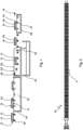
- the plateauless structural rollers 54 used can be found in Figure 2 .
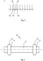
- An enlarged view of the partial area A is shown in Figure 3.
- deeply pierced recesses 80 can be seen, which are arranged directly adjacent to one another on the structural roller 54 and form raised areas. Walls 82 of two adjacent recesses 80 are arranged so close to one another that these raised areas do not have a plateau, but rather the shape of a tip 55.
- the plateau-less structural rollers 54 enable, as explained above, a homogeneous etching of the underside 14 of the substrate 10 in the preconditioning tank 50 with a comparatively low risk of undesirable local hydrophobization of the upper side 15 as a result of hydrophobizing liquid 52 being shoveled onto the upper side 15.
- the substrate 10 is transported into a rinsing basin 58, which contains deionized water 60 as a rinsing medium. There it is immersed in the deionized water 60, which serves as the rinsing liquid. The deionized water 60 is simultaneously used as a protective liquid.
- the substrate 10 is transported in the rinsing basin 58 by means of O-ring rollers 56, which minimize the contact surface for the substrate and thus enable an efficient rinsing process. Water 62 overflowing from the rinsing basin 58 is collected in an overflow basin 64.
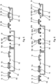
- a schematic representation of a section of the O-ring roller 56 shows Figure 4
- the O-ring roller 56 has a shaft element 72 and O-ring receptacles which are spaced apart from one another in the longitudinal direction of the shaft element 72 and which, in the case of the present example, are designed as recesses 74 in the shaft element 72, in each of which an O-ring 76 is arranged.
- the section of the O-ring roller 56 shown has two O-rings 76. This number is basically sufficient for transporting the flat substrate 10. Depending on requirements, for example in the case of larger or fragile substrates, a larger number of O-rings can be provided.
- the substrate 10 is transported further in the transport direction 16 by means of the O-ring shafts 56, it is The substrate 10 is then removed from the sink 58 in a horizontal manner.
- the O-ring rollers 56 are aligned accordingly for this purpose.
- the previously hydrophobicized edges 13 and the hydrophobicized underside 14 are free of deionized water 60 after the substrate 10 has been removed from the sink 58.
- the hydrophilic phosphosilicate glass layer 12 remaining on the upper side 15 of the substrate 10 additionally promotes the formation of the protective liquid film 66, whereby hydrophilicity in the present sense is understood to mean a contact angle between the surface and the wetting liquid of less than 15°.
- the hydrophilicity of the upper side 15 also counteracts the running down of deionized water from the protective liquid film 66.
- the substrate 10 is then transported into a treatment tank 60, which contains an etching solution 70.
- an etching solution 70 containing hydrofluoric acid and nitric acid is provided as the etching solution.
- an etching solution can be used which contains sulfuric acid in addition to hydrofluoric acid and nitric acid.
- the underside 14 is etched without the sensitive top side 15 of the substrate 10 being impaired.
- the running down of deionized water from the protective liquid film 66 or the creeping of etching solution 70 onto the upper side 15 of the substrate 10 is prevented. no streaks form on the underside 14 of the substrate 10 and the etching solution 70 is not contaminated or diluted by parts of the protective liquid film 66 running down from the top side 15 of the substrate 10.
- the advantages of the plateau-less structural rollers 54 described above also have a positive effect in the treatment tank, so that the risk of damage to the top side 15 of the substrate 10 is further reduced by the exclusive use of plateau-less structural rollers 54.
- the residence time of the substrates 10 in the preconditioning tank 50 must be selected such that the phosphosilicate glass layer 12 is reliably removed from the underside 14 of the substrate 10.
- the length of the preconditioning tank 50 must be adjusted accordingly if necessary.
- the substrates cannot be exposed to the hydrophobizing liquid 52 for an indefinite length of time. Otherwise, the hydrophobizing liquid 52 may creep onto the upper side 15 of the substrate 10 and cause considerable damage to this or the layers underneath.
- the residence time of the substrates in the preconditioning tank 50, or the length of this tank, must therefore be selected accordingly.
- Figure 5 illustrates in a schematic representation a second embodiment of the method according to the invention and the device according to the invention. This differs from the first embodiment of the Figure 1 by providing a sink 158 instead of the sink 58 which catches rinsing liquid.
- a surge pipe 160 is provided, by means of which the deionized water 60 used as rinsing liquid is applied to the top 15 of the silicon substrates.
- the deionized water 60 is applied in such an amount that water 162 dripping over the edges 13 of the silicon substrates 10 rinses the silicon substrates.
- a film of deionized water remains on the top 15 of the silicon substrates 10, which film is used as a protective liquid film 66. If rinsing of the substrates is not necessary, the deionized water or another suitable protective liquid can be applied to the upper side 15 of the silicon substrates 10 by means of the surge pipe 160 in such a metered manner that the protective liquid film 66 is formed, but only as little protective liquid as possible runs over the edges 13 of the silicon substrates 10 and drips into the rinsing basin 158.
- FIG. 6 illustrates in a schematic representation a third embodiment of the method according to the invention and the device according to the invention.
- This differs from the Figure 5 illustrated second embodiment, among other things, in that in addition to a surge pipe 160a, another surge pipe 160b is provided, which is arranged after the surge pipe 160a in the transport direction 16 of the substrates 10.
- the deionized water 60 is in turn applied to the substrates 10 as a protective liquid.
- the surge pipes 160a, 160b thus serve as application devices. Since they are arranged offset from one another in the transport direction 16 of the substrates, the deionized water 60 is applied several times as a protective liquid to the top side 15 of the substrates 10 by means of these surge pipes 160a, 160b.
- the deionized water 60 applied to the top side 15 of the substrates 10 by means of the surge pipe 160a forms a protective liquid film 66a, which in the respective application may not yet completely cover the top side 15 or may not yet have a sufficient thickness.
- the protective liquid film 66a may have formed islands, so that parts of the top side 15 are not covered with protective liquid or are not covered sufficiently.
- the multiple application of the protective liquid in this case the deionized water 60
- the protective liquid can result in a better distribution of the protective liquid in the corners of the substrates 10 and the edges of the substrates 10.
- the total amount of overflowing water 162 can be reduced by applying deionized water 60 or protective liquid several times. This enables a reduction in the effort required to carry out the process, particularly when using protective liquids other than water.
- FIG. 6 is another surge pipe 160c for applying the deionized water 60 to the Top side 15 of the substrates 10 is arranged above the treatment basin 68, and thus in the transport direction 16 of the substrates 10 after the rinsing basin 158.
- the surge pipe 160c like the surge pipes 160a and 160b, is intended to apply deionized water 60 as a protective liquid to the top side 15 of the substrates 10.
- FIG. 6 Three application devices for protective liquid are provided with the surge pipes 160a, 160b, 160c.
- one of these application devices preferably the surge pipe 160b or the surge pipe 160c, can be omitted.
- the remaining two surge pipes there are also several application devices arranged offset from one another in the transport direction 16 of the substrates 10, which enable repeated application of protective liquid, in this case deionized water 60, for the purpose of forming the protective liquid film.
- the protective liquid can be applied in such a metered manner that when protective liquid is applied to the upper side 15 of the substrate above the treatment tank 68, practically no protective liquid overflows and thus does not get into the etching solution 70, it has proven particularly advantageous to hold on to the surge pipe 160c, or more generally to an application device above the treatment tank 68.
- FIG. 6 The illustrated concept of several application devices arranged offset from one another in the transport direction 16 of the substrates 10 can be easily applied to the embodiment of Figure 1
- one or more application devices are provided after the rinsing basin, by means of which deionized water can be applied as a protective liquid to the upper side 15 of the substrates.
- the Figure 6 known surge pipes 160b or 160c or the like can be used.
- such a further application device could be arranged above the treatment tank 68 from Figure 1 be arranged.
Landscapes
- Weting (AREA)
- Cleaning By Liquid Or Steam (AREA)
- Cleaning Or Drying Semiconductors (AREA)
Description
- Die Erfindung betrifft ein Verfahren zum unterseitigen Behandeln eines flächigen Substrats sowie eine Vorrichtung zur Durchführung des Verfahrens gemäß dem Anspruch Unter anderem ist es im Bereich der Fertigung von Halbleiterbauelementen zum Teil erforderlich, flächige Substrate einseitig zu behandeln. Häufig wird zu diesem Zwecke eine Unterseite des Substrats behandelt. Je nach Anwendungsfall kann es dabei erforderlich sein, die Oberseite des Substrats vor einer Einwirkung des eingesetzten Behandlungsmediums oder etwaigen schädlichen Ausgasungen aus dem Behandlungsmedium zu schützen. Beispielsweise können Halbleiterbauelemente durch eine derartige Einwirkung auf die Oberseite geschädigt werden.
- Aus
WO 2011/047894 A1 ist bekannt, zum Schutz der Oberseite des Substrats auf die Oberseite eine Schutzflüssigkeit aufzusprühen, aufzuspritzen, aufzutropfen oder mittels Schwallrohren aufzubringen. Damit die Schutzflüssigkeit nicht in das Behandlungsmedium, üblicherweise eine Behandlungsflüssigkeit, gelangt, kann die Schutzflüssigkeit auf die Oberseite aufgebracht werden, ehe das Substrat unterseitig mit der Behandlungsflüssigkeit benetzt wird. Auf diese Weise kann die Menge der in die Behandlungsflüssigkeit eingetragenen Schutzflüssigkeit verringert werden. Wie inWO 2011/047894 A1 bereits dargelegt wird, kann aber selbst dann ein Herabtropfen von Schutzflüssigkeit in das Behandlungsmedium, beziehungsweise die Behandlungsflüssigkeit, nicht verhindert werden. Wird als Schutzflüssigkeit Wasser verwendet, hat dies eine Verdünnung der Behandlungsflüssigkeit und somit einen erhöhten Chemikalienverbrauch zur Folge. Zudem ist ein erhöhter Verfahrensaufwand erforderlich, um konstante Behandlungsbedingungen, beispielsweise eine konstante Zusammensetzung der Behandlungsflüssigkeit, und damit Prozesssicherheit zu gewährleisten. Wird ein anderes Material als Behandlungsflüssigkeit eingesetzt, so kommt es für gewöhnlich zu einer Kontamination des Behandlungsmediums mit ähnlichen und meist noch aufwändiger zu beherrschenden Folgen. - Weiterhin kann es an denjenigen Stellen, an welchen Schutzflüssigkeitstropfen von der Oberseite aus über Kanten des Substrats herablaufen und herabtropfen, zu einer Schlierenbildung während des Behandelns mit dem Behandlungsmedium kommen. Dies ist darauf zurückzuführen, dass an diesen Stellen die Unterseite des Substrats weniger stark geätzt wird. Diese Problematik tritt insbesondere auf, wenn als Behandlungsmedium eine Ätzlösung eingesetzt wird, mittels welcher ein vergleichsweise starker Materialabtrag von der Unterseite des Substrats vorgenommen wird. Ein derart starkes einseitiges Ätzen ist insbesondere bei neuen Siliziumsolarzellenherstellungsverfahren erforderlich, beispielsweise bei Verfahren zur Herstellung von Solarzellen mit passiviertem Emitter und passivierten Rückkontakten, den sogenannten PERC-Solarzellen. Infolge der geschilderten Ungleichheiten beim Ätzen ergibt sich ein inhomogenes Erscheinungsbild der Unterseite des Substrats und damit, neben eventuellen elektrischen Beeinträchtigungen des Halbleiterbauelements, ein inhomogenes Erscheinungsbild der fertigen Solarzelle. Zudem können in nachfolgenden Prozessschritten Probleme entstehen. So kann beispielsweise eine inhomogene Dicke einer auf der Unterseite des Substrats angeordnete Oxidschicht dazu führen, dass ein nachfolgend auf der Unterseite des Substrats durchgeführter Ätzschritt zu verschiedenen Zeiten beginnt.
- Darüber hinaus besteht bei der bekannten Verfahrensweise die Gefahr, dass eine als Behandlungsmedium eingesetzte, die Unterseite des Substrats benetzende Behandlungsflüssigkeit infolge eines Konzentrationsgefälles oder aufgrund von Benetzungsphänomenen über die Kanten des Substrats kriecht und auf diese Weise auf die Oberseite des Substrats gelangt. Dort kann sie die Oberfläche des Substrats lokal oder flächig beschädigen, beispielsweise infolge einer Ätzwirkung.
- Vor diesem Hintergrund liegt der vorliegenden Erfindung die Aufgabe zu Grunde, ein Verfahren zum unterseitigen Behandeln eines flächigen Substrats zur Verfügung zu stellen, mittels welchem zumindest ein Teil der geschilderten Nachteile aufwandsgünstig überwunden werden kann.
- Diese Aufgabe wird gelöst durch ein Verfahren mit den Merkmalen des Anspruchs 1.
- Weiterhin liegt der vorliegenden Erfindung die Aufgabe zu Grunde, eine Vorrichtung zur Verfügung zu stellen, mittels welcher dieses Verfahren durchgeführt und die Gefahr einer Schädigung der Oberseite des Substrats weitergehend verringert werden kann.
- Diese Aufgabe wird gelöst durch eine Vorrichtung mit den Merkmalen des nebengeordneten unabhängigen Anspruchs. Vorteilhafte Weiterbildungen sind jeweils Gegenstand abhängiger Unteransprüche.
- Das erfindungsgemäße Verfahren sieht vor, dass zum Zwecke des unterseitigen Behandelns eines flächigen Substrats mit einem Behandlungsmedium, zunächst eine Unterseite des Substrats mittels einseitigen, nasschemischen Ätzens hydrophobiert wird. Nachfolgend wird auf einer Oberseite des Substrats ein Schutzflüssigkeitsfilm ausgebildet. Danach wird das Behandlungsmedium mit der Unterseite des Substrats in Kontakt gebracht und dabei die Oberseite mittels des Schutzflüssigkeitsfilms gegen ein Einwirken des Behandlungsmediums und/oder dessen Ausgasungen geschützt.
- Infolge der Hydrophobierung gelangt bei dieser Vorgehensweise nach der Entnahme des Substrats aus der Schutzflüssigkeit keine Schutzflüssigkeit von der Oberseite auf die Unterseite des Substrats. Die oben geschilderte Problematik der Schlierenbildung und die hieraus resultierenden Nachteile können daher vermieden werden. Darüber hinaus kann verhindert werden, dass Behandlungsmedium, wie oben beschrieben, von der Unterseite auf die Oberseite kriecht. Dies ist insbesondere bei schwefelsäurefreien Behandlungsmedien von Vorteil. Überdies kann durch die Hydrophobierung in vielen Anwendungsfällen ein Trocknungsschritt eingespart werden, der bei bislang bekannten Verfahren vor einem weiteren Prozessschritt erforderlich wäre. Des Weiteren kann das Verfahren als Durchlaufverfahren konzipiert werden und ist einfach in bereits bestehende Durchlaufanlagen integrierbar.
- Eine Hydrophobierung im Sinne der vorliegenden Erfindung ist gegeben, wenn die Schutzflüssigkeit die hydrophobierte Fläche mit einem Kontaktwinkel größer als 60° benetzt.
- Mittels der Schutzflüssigkeit kann die Oberseite grundsätzlich gegen das Behandlungsmedium an sich, welches insbesondere als Flüssigkeit oder Gas beziehungsweise Gasgemenge vorliegen kann, geschützt werden. Wird eine Behandlungsflüssigkeit eingesetzt, so wird der Schutzflüssigkeitsfilm vorzugsweise sowohl als Schutz gegenüber auf die Oberseite gelangende Behandlungsflüssigkeit als auch als Schutz gegen auf die Oberseite des Substrats gelangende Ausgasungen aus der Behandlungsflüssigkeit verwendet. Solche Ausgasungen können beispielsweise durch ein teilweises Verdampfen der Behandlungsflüssigkeit entstehen.
- Vorzugsweise wird als Schutzflüssigkeit Wasser verwendet, besonders bevorzugt deionisiertes Wasser. Dieses hat sich in vielen Anwendungsfällen bewährt und kann meistens vergleichsweise einfach aufbereitet oder entsorgt werden.
- Vorteilhafterweise wird ein Siliziumsubstrat behandelt und zum Zwecke des Hydrophobierens der Unterseite dieses Siliziumsubstrats eine Silikatglasschicht, beispielsweise eine Phosphor- oder eine Borsilikatglasschicht, von der Unterseite des Siliziumsubstrats entfernt. Derartige Silikatglasschichten werden bei der Herstellung von Halbleiterbauelementen häufig eingesetzt, insbesondere bei der Herstellung von Siliziumsolarzellen, sodass dies eine besonders aufwandsgünstige Verfahrensführung ermöglicht. Zudem kann für die Hydrophobierung des Siliziumsubstrats auf bewährte Techniken zurückgegriffen werden.
- Bei einer Ausführungsvariante des Verfahrens wird zum Zwecke des Ausbildens des Schutzflüssigkeitsfilms mittels einer Auftragvorrichtung eine Schutzflüssigkeit auf die Oberseite des Substrats aufgebracht. Als Auftragvorrichtung können grundsätzlich alle an sich bekannten Auftragvorrichtungen wie beispielsweise Sprühdüsen verwendet werden. Vorzugsweise wird wenigstens ein Schwallrohr als Auftragvorrichtung eingesetzt.
- Eine alternative Ausführungsvariante sieht vor, das Substrat zum Zwecke des Ausbildens des Schutzflüssigkeitsfilms in die Schutzflüssigkeit einzutauchen und aus dieser zu entnehmen. Bei der Entnahme des Substrats aus der Schutzflüssigkeit wird das Substrat derart ausgerichtet, dass es sich in einer im Wesentlichen horizontal verlaufenden Ebene erstreckt, sodass auf einer Oberseite des Substrats der gewünschte Schutzflüssigkeitsfilm verbleibt. Dass das Substrat bei der Entnahme aus der Schutzflüssigkeit derart ausgerichtet wird, dass es sich in einer im Wesentlichen horizontal verlaufenden Ebene erstreckt, ist dahingehend zu verstehen, dass geringfügige Abweichungen von der Horizontalen kurzzeitig möglich sind. Wie lange von der Horizontalen abgewichen werden kann und in welchem exakten Umfang, hängt von den Eigenschaften verwendeter Materialien ab, insbesondere von einer Viskosität der Schutzflüssigkeit und Adhäsionskräften zwischen der Oberseite des Substrats und der Schutzflüssigkeit. Aufwändige Auftragsvorrichtungen wie Sprühdüsen, Schwallrohre oder anderes sind bei dieser Ausführungsvariante nicht erforderlich. Auch bedarf es keiner Dosierungsvorrichtungen und Messeinrichtungen, die erforderlich wären, um die Position des Substrats zu bestimmen und zum richtigen Zeitpunkt eine exakte Dosierung von Schutzflüssigkeit auf die Oberseite des Substrats zu gewährleisten und auf diese Weise die Menge der von der Oberseite des Substrats herab laufenden Schutzflüssigkeit einzugrenzen.
- Bevorzugt werden vor dem Eintauchen des Substrats in die Schutzflüssigkeit die Kanten des Substrats ebenfalls, vorzugsweise vollständig, hydrophobiert. Dies erfolgt vorteilhafterweise in einem gemeinsamen Verfahrensschritt mit dem Hydrophobieren der Unterseite des Substrats. Das heißt, dass die Unterseite und die Kanten des Substrats gleichzeitig in einem einheitlichen Verfahrensschritt hydrophobiert werden. Mittels der hydrophobierten Kanten kann die Gefahr des Kriechens von Behandlungsflüssigkeit auf die Oberseite des Substrats, die grundsätzlich bestehen kann, wenn die Behandlungsflüssigkeit aus irgendeinem Grund mit nicht hydrophobierten Kantenteilen in Kontakt gerät, nochmals verringert werden.
- Die Unterseite des Substrats kann vorteilhaft mittels einseitigen, nasschemischen Ätzens hydrophobiert werden. Einseitig bedeutet in diesem Zusammenhang, dass an die Oberseite keine für das nasschemische Ätzen verwendete Ätzlösung herangeführt wird. Auf diese Weise können Anlagen eingesetzt werden, die sich in der Praxis bereits in anderem Zusammenhang bewährt haben. Überdies können bei dieser Verfahrensvariante die Kanten in demselben Verfahrensschritt aufwandsgünstig ganz oder teilweise ebenfalls hydrophobiert werden.
- Besonders bevorzugt wird zum Zwecke des Hydrophobierens der Unterseite des Substrats das Substrat von unten mit einer Ätzflüssigkeit benetzt. Dies ermöglicht eine Hydrophobierung in industriellem Maßstab, unter anderem in Durchlaufanlagen. Insbesondere kann das Substrat quasi schwimmend an der Oberfläche der Ätzflüssigkeit derart durch ein Ätzbecken geführt werden, dass die Ätzflüssigkeit die Unterseite des Substrats benetzt. Grundsätzlich kann die Ätzflüssigkeit jedoch auch auf eine beliebige andere Weise an die Unterseite des Substrats herangeführt werden, beispielsweise mittels Transportrollen, welche die Ätzflüssigkeit aufnehmen und an die auf ihnen transportierten Substrate weiterreichen. Die Kanten können bei diesen Verfahrensvarianten vorteilhafterweise ganz oder teilweise ebenfalls hydrophobiert werden.
- Vorteilhafterweise wird nach dem zum Zwecke des Hydrophobierens vorgenommenen nasschemischen Ätzen das Substrat gespült. Bei einer Verfahrensvariante erfolgt dies, indem eine Spülflüssigkeit auf das Substrat aufgebracht wird, beispielsweise mittels eines Schwallrohres oder einer anderen Auftragvorrichtung. Die Menge der auf das Substrat aufgebrachten Spülflüssigkeit wird dabei derart gewählt, dass mindestens die Hälfte, vorzugsweise mindestens 70 % und besonders bevorzugt mindestens 80 %, der aufgebrachten Menge an Spülflüssigkeit von dem Substrat abtropft und verbliebene Ätzflüssigkeitsreste abspült. Die letztlich auf der Oberseite verbleibende Spülflüssigkeit wird im Weiteren als Schutzflüssigkeitsfilm verwendet, sodass es für dessen Ausbildung keines zusätzlichen Verfahrensschrittes bedarf.
- Eine alternative Verfahrensvariante sieht vor, dass das Substrat zum Zwecke des Spülens in eine Spülflüssigkeit eingetaucht und diese Spülflüssigkeit gleichzeitig als Schutzflüssigkeit verwendet wird. Eine Entnahme des Substrats aus der Spülflüssigkeit stellt sodann gleichzeitig die Entnahme des Substrats aus der Schutzflüssigkeit dar. Das Substrat wird bei der Entnahme aus der Schutzflüssigkeit in der oben beschriebenen Weise derart ausgerichtet, dass es sich in einer im Wesentlichen horizontal verlaufenden Ebene erstreckt, sodass auf der Oberseite des Substrats der Schutzflüssigkeitsfilm verbleibt. Auf diese Weise kann das Verfahren besonders schnell und aufwandsgünstig realisiert werden.
- Als Spülflüssigkeit kann grundsätzlich jede für den jeweiligen Anwendungsfall geeignete Flüssigkeit verwendet werden. Vorzugsweise wird Wasser verwendet und bei der Herstellung von Halbleiterbauelementen wie beispielsweise Solarzellen aus Kontaminationsgründen besonders bevorzugt deionisiertes Wasser.
- In einer bewährten Verfahrensvariante wird als Behandlungsmedium ein Ätzmedium verwendet und die Unterseite des Substrats mittels dieses Ätzmediums geätzt. Bei diesem Ätzen kann ein Materialabtrag erfolgen. Beispielsweise kann es sich um ein Politurätzen handeln. Insbesondere kann die Unterseite eines Siliziumsolarzellensubstrats geätzt werden. Diese Verfahrensvariante hat sich daher insbesondere bei der Herstellung von neuartigen, hocheffizienten Solarzellen mit passivierten Emittern und passivierten Rückkontakten bewährt.
- Vorteilhafterweise wird zum Zwecke des Ausbildens des Schutzflüssigkeitsfilms die Schutzflüssigkeit mehrmals auf die Oberseite des Substrats aufgebracht. Das heißt, dass die Schutzflüssigkeit in mehreren, mit zeitlichem Versatz ablaufenden Auftragsvorgängen aufgebracht wird. Beispielsweise beginnt ein zweiter Auftragsvorgang nachdem ein erster Auftragsvorgang bereits begonnen wurde oder nachdem der erste Auftragsvorgang beendet wurde. Vorzugsweise beginnt der zweite Auftragsvorgang nachdem der erste Auftragsvorgang beendet wurde.
- Es hat sich gezeigt, dass mittels des mehrmaligen Aufbringens der Schutzflüssigkeit die Schutzflüssigkeit besser auf der Oberseite des Substrats verteilt werden kann. Insbesondere hat sich gezeigt, dass die Schutzflüssigkeit in diversen Anwendungsfällen besser in Ecken des Substrats und an Randbereiche des Substrats gelangen kann. Die Gefahr einer Bildung von Inseln aus Schutzflüssigkeit auf der Oberseite des Substrats, welche Teile der Oberseite des Substrats unbedeckt lassen, wird verringert oder gar vermieden. Je nach Anwendungsfall kann daher die insgesamt auf die Oberseite des Substrats zum Zwecke der Ausbildung des Schutzflüssigkeitsfilms aufgebrachte Menge an Schutzflüssigkeit verringert werden, ohne dass dies mit einer erhöhten Gefahr von nicht mit dem Schutzflüssigkeitsfilm bedeckter Teilbereiche der Oberseite des Substrats einhergeht. Insbesondere bei der oben beschriebenen Verfahrensvariante, bei welcher das Substrat in eine Schutzflüssigkeit eingetaucht und bei der Entnahme derart ausgerichtet wird, dass auf der Oberseite des Substrats der Schutzflüssigkeitsfilm verbleibt, kann das beschriebene mehrmalige Aufbringen der Schutzflüssigkeit zudem dazu dienen, den Schutzflüssigkeitsfilm zu verstärken oder zu vervollständigen. Dies kann in einzelnen Anwendungsfällen vorteilhaft sein, beispielsweise wenn bei einer ungünstigen Verfahrensführung während der Entnahme des Substrats aus der Schutzflüssigkeit zu viel Schutzflüssigkeit von der Oberseite des Substrats herunterläuft oder im weiteren Verfahrensverlauf zu viel Schutzflüssigkeit aus dem Schutzflüssigkeitsfilm verdampft. Nebenbei sei bemerkt, dass die oben beschriebene horizontale Entnahme des Substrats aus der Schutzflüssigkeit und das damit einhergehende Verbleiben eines Schutzflüssigkeitsfilms auf der Oberseite des Substrats ein Aufbringen von Schutzflüssigkeit auf die Oberseite des Substrats darstellt.
- Die erfindungsgemäße Vorrichtung weist ein Vorkonditionierungsbecken auf, welches eine Flüssigkeit enthält, mittels welcher zu behandelnde Substrate hydrophobiert werden können. In einer Transportrichtung der Substrate dem Vorkonditionierungsbecken nachgeordnet ist ein Spülbecken vorgesehen. Dieses kann ein Spülmedium enthalten oder dazu vorgesehen sein, abtropfende Spülflüssigkeit aufzufangen. Weiterhin ist ein in der Transportrichtung der Substrate dem Spülbecken nachgeordnetes Behandlungsbecken vorgesehen, welches eine Behandlungsflüssigkeit enthält. In dem Vorkonditionierungsbecken sind Transportrollen vorgesehen, welche zum Transport der Substrate durch das Vorkonditionierungsbecken geeignet sind. Diese Transportrollen sind mehrheitlich, vorzugsweise ausschließlich, als plateaulose Strukturrollen ausgeführt.
- Unter plateaulosen Strukturrollen sind vorliegend Transportrollen zu verstehen, welche an ihrer Oberfläche ringförmige Ausnehmungen, sogenannte Einstiche, aufweisen, welche die Transportrolle umfänglich umschließen. Diese Ausnehmungen sind unmittelbar aneinander angrenzend auf der Transportrolle angeordnet. An denjenigen Stellen, an welchen die Ausnehmungen aneinandergrenzen, stoßen die Wandungen benachbarter Ausnehmungen aufeinander und bilden erhabene Bereiche auf der Transportrollenoberfläche aus. Im Fall von plateaulosen Strukturrollen sind die benachbarten Ausnehmungen derart nah aneinander angrenzend angeordnet, dass diese erhabenen Bereiche keine Plateaus mehr darstellen, sondern vielmehr als eine Art Spitzen angesehen werden können. Mittels plateauloser Strukturrollen kann eine gleichmäßige Benetzung der Unterseite des Substrats realisiert werden. Bei dem Ätzvorgang entstehende Blasen werden homogen über die Substratunterseite verteilt und immer wieder abgestreift. Dies ermöglicht, vor allem bei hohen Ätzraten, ein homogeneres Ätzergebnis. Ferner hat sich gezeigt, dass bei einer Verwendung von plateaulosen Strukturrollen die Gefahr, dass eine Transportrolle die hydrophobierende Flüssigkeit oder eine andere Behandlungsflüssigkeit in dem Moment, in welchem das Substrat diese Transportrolle verlässt, auf die Oberseite dieses Substrats befördert, gegenüber Vollrollen erheblich verringert ist. Die Verwendung plateauloser Strukturrollen in dem Vorkonditionierungsbecken ermöglicht somit eine weitergehende Verringerung der Gefahr der Schädigung der Oberseite des Substrats.
- Vorteilhafterweise sind in dem Spülbecken zum Transport der Substrate mehrheitlich O-Ring-Rollen, welche jeweils ein Wellenelement sowie mehrere in Längsrichtung des Wellenelements voneinander beabstandete O-Ring-Aufnahmen aufweisen, als Transportrollen vorgesehen. In den genannten O-Ring-Aufnahmen ist jeweils ein O-Ring angeordnet ist, welcher das Wellenelement sowie die jeweilige O-Ring-Aufnahme umfänglich umschließt. In einer verschlechterten Ausführungsform können anstelle von O-Ring-Aufnahmen und darin angeordneten O-Ringen Ausformungen des Wellenelements vorgesehen sein.
- Vorzugsweise sind in dem Spülbecken ausschließlich die beschriebenen O-Ring-Rollen als Transportrollen angeordnet. Auf diese Weise wird die Kontaktfläche zwischen Transportrolle und darauf transportiertem Substrat minimiert. Infolgedessen kann noch an dem Substrat anhaftende, hydrophobierende Flüssigkeit aus dem Vorkonditionierungsbecken besser weggespült werden. O-Ring-Rollen haben eine sehr geringe Neigung Flüssigkeit auf die Oberseiten der Substrate zu befördern, wenn das Substrat die O-Ring-Rolle verlässt. Dennoch ist ihre Verwendung in dem Vorkonditionierungsbecken oder dem Behandlungsbecken nicht vorteilhaft, da sie Rollenspuren hinterlassen, welche dem Ziel eines homogenen Ätzergebnisses entgegenwirken. Wie sich herausgestellt hat, überwiegen im Spülbecken jedoch die Vorteile der äußerst geringen Gefahr einer Schädigung der Substratoberseiten durch auf die Oberseite geschaufelte Flüssigkeit.
- Vorteilhafterweise sind in dem Behandlungsbecken zum Transport der Substrate durch das Behandlungsbecken mehrheitlich, vorzugsweise ausschließlich, plateaulose Strukturrollen als Transportrollen vorgesehen. Die bereits im Zusammenhang mit dem Vorkonditionierungsbecken beschriebenen Wirkungen der plateaulosen Strukturrollen wirken sich im Behandlungsbecken ebenfalls vorteilhaft aus und ermöglichen eine weitergehende Verringerung der Gefahr einer Schädigung der Oberseite der behandelten Substrate.
- Als hydrophobierende Flüssigkeit kann in dem Vorkonditionierungsbecken eine flusssäurehaltige Ätzlösung vorgesehen sein. Diese hat sich insbesondere bei der Entfernung von Silikatglasschichten von Siliziumsubstraten bewährt.
- Als Behandlungsflüssigkeit kann eine Ätzlösung vorgesehen sein, welche Flusssäure und ein Oxidationsmittel, vorzugsweise Salpetersäure oder Wasserstoffperoxid, enthält. In einer anderen Ausgestaltungsvariante kann als Behandlungsflüssigkeit eine Ätzlösung vorgesehen sein, welche neben der genannten Flusssäure und dem genannten Oxidationsmittel zusätzlich ein Additiv, vorzugsweise Schwefelsäure, enthält. Beide Varianten haben sich insbesondere bei der Behandlung von Siliziumsubstraten bewährt.
- Vorteilhafterweise sind mehrere Auftragvorrichtungen vorgesehen, mittels welchen eine Schutzflüssigkeit auf eine Oberseite der Substrate aufbringbar ist. Diese mehreren Auftragvorrichtungen sind in der Transportrichtung der Substrate versetzt zueinander angeordnet. Dies ermöglicht es, wie oben beschrieben, Schutzflüssigkeit mehrmals auf die Oberseite der Substrate aufzubringen.
- Vorzugsweise ist wenigstens eine der mehreren Auftragvorrichtungen über dem Spülbecken angeordnet. Eine Auftragvorrichtung kann beispielsweise aus einem Schwallrohr oder dergleichen gebildet sein oder aus Transportrollen, mittels welchen die Substrate vollständig in eine in dem Spülbecken angeordnete Spülflüssigkeit eingetaucht durch zumindest einen Teil des Spülbeckens transportiert werden.
- Es hat sich als vorteilhaft erwiesen, dass wenigstens eine der mehreren Auftragvorrichtungen in der Transportrichtung der Substrate nach dem Spülbecken angeordnet ist. Auf diese Weise können zwischenzeitlich erfolgte Verluste an Schutzflüssigkeit auf der Oberseite der Substrate, beispielsweise infolge von Verdampfungseffekten, komfortabel ausgeglichen werden.
- Vorteilhafterweise ist wenigstens eine der mehreren Auftragvorrichtungen über dem Behandlungsbecken angeordnet. Auf diese Weise können Verdampfungsverluste oder Fehlmengen an Schutzflüssigkeit auf der Oberseite der Substrate während des Einwirkens der Behandlungsflüssigkeit kompensiert werden. Die Gefahr, dass erneut Fehlmengen oder Verdampfungsverluste an der Schutzflüssigkeit entstehen, wird auf diese Weise minimiert.
- Im Weiteren wird die Erfindung anhand von Figuren näher erläutert. Soweit zweckdienlich, sind hierin gleich wirkende Elemente mit gleichen Bezugszeichen versehen. Die Erfindung ist nicht auf die in den Figuren dargestellten Ausführungsbeispiele beschränkt - auch nicht in Bezug auf funktionale Merkmale. Die bisherige Beschreibung wie auch die nachfolgende Figurenbeschreibung enthalten zahlreiche Merkmale, die in den abhängigen Unteransprüchen teilweise zu mehreren zusammengefasst wiedergegeben sind. Diese Merkmale wie auch alle übrigen oben und in der nachfolgenden Figurenbeschreibung offenbarten Merkmale wird der Fachmann jedoch auch einzeln betrachten und zu sinnvollen weiteren Kombinationen zusammenfügen. Insbesondere sind diese Merkmale jeweils einzeln und in beliebiger geeigneter Kombination mit dem Verfahren und/oder der Vorrichtung der unabhängigen Ansprüche kombinierbar. Es zeigen:
- Figur 1
- Ein erstes Ausführungsbeispiel des erfindungsgemäßen Verfahrens sowie der erfindungsgemäßen Vorrichtung in einer schematischen Darstellung
- Figur 2
- Seitenansicht einer plateaulosen Strukturrolle aus
Figur 1 - Figur 3
- Detaildarstellung eines Teilbereichs A aus
Figur 2 - Figur 4
- Schematische Darstellung einer O-Ring-Rolle
- Figur 5
- Ein zweites Ausführungsbeispiel des erfindungsgemäßen Verfahrens sowie der erfindungsgemäßen Vorrichtung in einer schematischen Darstellung
- Figur 6
- Ein drittes Ausführungsbeispiel des erfindungsgemäßen Verfahrens sowie der erfindungsgemäßen Vorrichtung in einer schematischen Darstellung
-
Figur 1 illustriert in einer schematischen Darstellung ein Ausführungsbeispiel des erfindungsgemäßen Verfahrens wie auch der erfindungsgemäßen Vorrichtung. Bei diesem Ausführungsbeispiel wird ein Siliziumsubstrat 10, welches an seiner gesamten Oberfläche mit einer Phosphorsilikatglasschicht 12 versehen ist, beispielsweise infolge einer Phosphordiffusion, mittels Transportrollen in einer Transportrichtung 16 durch eine Abfolge verschiedener Becken transportiert. Zunächst werden in einem Vorkonditionierungsbecken 50 eine Unterseite 14 sowie die Kanten 13 des Substrats 10 hydrophobiert. Zu diesem Zweck wird die Unterseite 14 des Substrats 10 von unten mit einer hydrophobierenden Flüssigkeit 52, im vorliegenden Ausführungsbeispiel mit einer flusssäurehaltigen Ätzlösung, benetzt. Im Vorkonditionierungsbecken sind ausschließlich plateaulose Strukturrollen 54 als Transportrollen vorgesehen, welche ein homogenes Ätzen ermöglichen. Im Ergebnis wird die Phosphorsilikatglasschicht 12 gleichmäßig an der Unterseite 14 sowie den Kanten 13 entfernt. - Eine Seitenansicht der im Ausführungsbeispiel der
Figur 1 verwendeten plateaulosen Strukturrollen 54 findet sich inFigur 2 . Eine vergrößerte Darstellung des Teilbereichs A ist in Figur 3 wiedergegeben. Hierin sind tief eingestochene Ausnehmungen 80 erkennbar, welche unmittelbar aneinander angrenzend auf der Strukturrolle 54 angeordnet sind und erhabene Bereiche ausbilden. Wandungen 82 zweier benachbarter Ausnehmungen 80 sind dabei derart nah aneinander angrenzend angeordnet, dass diese erhabenen Bereiche kein Plateau aufweisen, sondern vielmehr die Gestalt einer Spitze 55. Die plateaulosen Strukturrollen 54 ermöglichen, wie oben erläutert, im Vorkonditionierungsbecken 50 ein homogenes Ätzen der Unterseite 14 des Substrats 10 bei vergleichsweise geringer Gefahr einer unerwünschten lokalen Hydrophobierung der Oberseite 15 in Folge von auf die Oberseite 15 geschaufelter, hydrophobierende Flüssigkeit 52. - Im Weiteren Verfahrensverlauf wird das Substrat 10 in ein Spülbecken 58 transportiert, welches als Spülmedium deionisiertes Wasser 60 enthält. Dort wird es in das als Spülflüssigkeit dienende deionisierte Wasser 60 eingetaucht. Das deionisierte Wasser 60 wird dabei gleichzeitig als Schutzflüssigkeit verwendet. Der Transport des Substrats 10 im Spülbecken 58 erfolgt mittels O-Ring-Rollen 56, welche die Auflagefläche für das Substrat minimieren und auf diese Weise einen effizienten Spülvorgang ermöglichen. Aus dem Spülbecken 58 überlaufendes Wasser 62 wird in einem Überlaufbecken 64 aufgefangen.
- Eine schematische Darstellung eines Abschnitts der O-Ring-Rolle 56 zeigt
Figur 4 . Die O-Ring-Rolle 56 weist ein Wellenelement 72 auf sowie in Längsrichtung des Wellenelements 72 voneinander beabstandete O-Ring-Aufnahmen, welche im Fall des vorliegenden Beispiels als Ausnehmungen 74 in dem Wellenelement 72 ausgeführt sind, in welchen jeweils ein O-Ring 76 angeordnet ist. Der inFigur 4 dargestellte Abschnitt der O-Ring-Rolle 56 weist zwei O-Ringe 76 auf. Diese Zahl ist grundsätzlich für den Transport des flächigen Substrats 10 ausreichend. Je nach Bedarf kann, beispielsweise bei größeren oder zerbrechlichen Substraten, eine größere Anzahl von O-Ringen vorgesehen werden. - Wird das Substrat 10 mittels der O-Ring-Wellen 56 in der Transportrichtung 16 weitertransportiert, so wird es auf diese Weise aus dem Spülbecken 58 entnommen. Das Substrat 10 erstreckt sich dabei in einer horizontal verlaufenden Ebene. Die O-Ring-Rollen 56 sind zu diesem Zweck entsprechend ausgerichtet. Die zuvor hydrophobierten Kanten 13 sowie die hydrophobierte Unterseite 14 sind nach der Entnahme des Substrats 10 aus dem Spülbecken 58 frei von deionisiertem Wasser 60. Auf der Oberseite 15 hingegen verbleibt ein Schutzflüssigkeitsfilm 66 aus deionisiertem Wasser 60. Die auf der Oberseite 15 des Substrats 10 verbliebene, hydrophile Phosphorsilikatglasschicht 12 begünstigt die Ausbildung des Schutzflüssigkeitsfilms 66 zusätzlich, wobei Hydrophilie im vorliegenden Sinne ein Kontaktwinkel zwischen Oberfläche und benetzender Flüssigkeit von weniger als 15° zu verstehen ist. Die Hydrophilie der Oberseite 15 wirkt zudem einem Herablaufen von deionisiertem Wasser aus dem Schutzflüssigkeitsfilm 66 zusätzlich entgegen.
- Nachfolgend wird das Substrat 10 in ein Behandlungsbecken 60 transportiert, welches eine Ätzlösung 70 enthält. Als Ätzlösung ist im vorliegenden Ausführungsbeispiel eine Flusssäure und Salpetersäure enthaltende Ätzlösung 70 vorgesehen. Alternativ kann unter anderem eine Ätzlösung verwendet werden, welche neben Flusssäure und Salpetersäure Schwefelsäure enthält. Indem das Substrat mittels der plateaulosen Strukturrollen 54 durch das Behandlungsbecken 68 transportiert wird, wird die Ätzlösung 70 mit der Unterseite 14 des Substrats in Kontakt gebracht und geätzt. Die Oberseite 15 des Substrats 10 ist hingegen durch den Schutzflüssigkeitsfilm 66 gegen auf die Oberseite 15 gelangende Ätzlösung 70 und gegen eine Einwirkung von Ausgasungen aus der Ätzlösung 70, insbesondere gegen ätzende Dämpfe, geschützt. Die Unterseite 14 wird geätzt, ohne dass die empfindliche Oberseite 15 des Substrats 10 beeinträchtigt wird. Ein Herablaufen von deionisiertem Wasser aus dem Schutzflüssigkeitsfilm 66 oder ein Kriechen von Ätzlösung 70 auf die Oberseite 15 des Substrats 10 ist unterbunden. Es kommt zu keiner Schlierenbildung auf der Unterseite 14 des Substrats 10 und die Ätzlösung 70 wird nicht durch von der Oberseite 15 des Substrats 10 herablaufende Teile des Schutzflüssigkeitsfilms 66 kontaminiert beziehungsweise verdünnt. Die oben beschriebenen Vorteile der plateaulosen Strukturrollen 54 wirken sich auch im Behandlungsbecken positiv aus, sodass die Gefahr einer Schädigung der Oberseite 15 des Substrats 10 durch die ausschließliche Verwendung plateauloser Strukturrollen 54 weiter verringert wird.
- Eine Verweildauer der Substrate 10 in dem Vorkonditionierungsbecken 50 ist so zu wählen, dass die Phosphorsilikatglasschicht 12 mit Sicherheit von der Unterseite 14 des Substrats 10 entfernt wird. Die Länge des Vorkonditionierungsbeckens 50 ist gegebenenfalls entsprechend anzupassen. Die Substrate können jedoch nicht beliebig lange der hydrophobierenden Flüssigkeit 52 ausgesetzt werden. Andernfalls kann es dazu kommen, dass die hydrophobierende Flüssigkeit 52 auf die Oberseite 15 des Substrats 10 kriecht und diese oder darunter liegende Schichten in erheblichem Umfang schädigt. Die Verweildauer der Substrate im Vorkonditionierungsbecken 50, beziehungsweise die Länge dieses Beckens, sind daher entsprechend zu wählen. Im Übrigen kann es je nach Dicke der Phosphorsilikatglasschicht 12 oder in Abhängigkeit von Materialeigenschaften und Dicken anderer zu entfernender Schichten vorteilhaft sein, angepasste Transportrollen zu verwenden. Beispielsweise können tiefer oder weniger tief eingestochene plateauloses Strukturrollen Verwendung finden.
-
Figur 5 illustriert in einer schematischen Darstellung ein zweites Ausführungsbeispiel des erfindungsgemäßen Verfahrens sowie der erfindungsgemäßen Vorrichtung. Dieses unterscheidet sich von dem ersten Ausführungsbeispiel derFigur 1 dadurch, dass anstelle des Spülbeckens 58 ein Spülbecken 158 vorgesehen ist, welches Spülflüssigkeit auffängt. Zum Zwecke des Spülens ist ein Schwallrohr 160 vorgesehen, mittels welchem das als Spülflüssigkeit verwendete, deionisierte Wasser 60 auf die Oberseite 15 der Siliziumsubstrate aufgebracht wird. Das deionisierte Wasser 60 wird in solch einer Menge aufgebracht, dass über die Kanten 13 der Siliziumsubstrate 10 herabtropfendes Wasser 162 die Siliziumsubstrate spült. Ist das Siliziumsubstrat 10 unter dem Schwallrohr 160 durchgelaufen verbleibt auf der Oberseite 15 der Siliziumsubstrate 10 ein Film aus deionisiertem Wasser, welcher als Schutzflüssigkeitsfilm 66 verwendet wird. Ist ein Spülen der Substrate nicht erforderlich, so kann mittels des Schwallrohres 160 das deionisierte Wasser, oder eine andere geeignete Schutzflüssigkeit, grundsätzlich derart dosiert auf die Oberseite 15 der Siliziumsubstrate 10 aufgebracht werden, dass der Schutzflüssigkeitsfilm 66 ausgebildet wird, aber nur möglichst wenig Schutzflüssigkeit über die Kanten 13 der Siliziumsubstrate 10 läuft und in das Spülbecken 158 tropft. -
Figur 6 illustriert in einer schematischen Darstellung ein drittes Ausführungsbeispiel des erfindungsgemäßen Verfahrens sowie der erfindungsgemäßen Vorrichtung. Dieses unterscheidet sich von dem inFigur 5 dargestellten, zweiten Ausführungsbeispiel unter anderem dadurch, dass neben einem Schwallrohr 160a ein weiteres Schwallrohr 160b vorgesehen ist, welches in der Transportrichtung 16 der Substrate 10 nach dem Schwallrohr 160a angeordnet ist. Mittels dieser Schwallrohre 160a und 160b wird wiederum das deionisierte Wasser 60 als Schutzflüssigkeit auf die Substrate 10 aufgebracht. Die Schwallrohre 160a, 160b dienen somit als Auftragvorrichtungen. Da sie in der Transportrichtung 16 der Substrate versetzt zueinander angeordnet sind, wird mittels dieser Schwallrohre 160a, 160b das deionisierte Wasser 60 mehrmals als Schutzflüssigkeit auf die Oberseite 15 der Substrate 10 aufgebracht. - Das mittels des Schwallrohres 160a auf die Oberseite 15 der Substrate 10 aufgebrachte deionisierte Wasser 60 bildet einen Schutzflüssigkeitsfilm 66a aus, welcher die Oberseite 15 im jeweiligen Anwendungsfall möglicherweise noch nicht vollständig bedeckt oder noch keine hinreichende Dicke aufweist. Insbesondere kann der Schutzflüssigkeitsfilm 66a Inseln gebildet haben, sodass Teile der Oberseite 15 nicht oder nicht hinreichend mit Schutzflüssigkeit bedeckt sind. Durch den zweiten Auftrag von deionisiertem Wasser 60 als Schutzflüssigkeit mittels des Schwallrohres 160b können Fehlstellen im Schutzflüssigkeitsfilm 66a ausgeglichen werden, sodass ein die Oberseite 15 der Substrate 10 vollständig bedeckender Schutzflüssigkeitsfilm 66b vorliegt. Weist der Schutzflüssigkeitsfilm 66a lediglich keine hinreichende Dicke auf, so bewirkt der Auftrag des deionisierten Wassers 60 mittels des Schwallrohres 160b einen dickeren Schutzflüssigkeitsfilm 66b.
- Wie oben beschrieben, kann durch das mehrfache Aufbringen der Schutzflüssigkeit, im vorliegenden Fall des deionisierten Wassers 60, eine bessere Verteilung der Schutzflüssigkeit in Ecken der Substrate 10 und den Rändern der Substrate 10 bewirkt werden. Nach Durchlaufen des Spülbeckens 158 liegt bei dem Ausführungsbeispiel der
Figur 6 somit ein Schutzflüssigkeitsfilm 66c vor, welcher die Oberseite 15 der Substrate 10 vollständig und homogen bedeckt. Je nach Anwendungsfall kann durch das mehrmalige Aufbringen von deionisiertem Wasser 60, beziehungsweise Schutzflüssigkeit, die Gesamtmenge überlaufenden Wassers 162 reduziert werden. Dies ermöglicht, insbesondere bei Verwendung anderer Schutzflüssigkeiten als Wasser, eine Reduktion des Aufwandes der Verfahrensführung. - Im Ausführungsbeispiel der
Figur 6 ist ein weiteres Schwallrohr 160c zum Aufbringen des deionisierten Wassers 60 auf die Oberseite 15 der Substrate 10 über dem Behandlungsbecken 68, und somit in der Transportrichtung 16 der Substrate 10 nach dem Spülbecken 158, angeordnet. Das Schwallrohr 160c ist ebenso wie die Schwallrohre 160a und 160b dazu vorgesehen, deionisiertes Wasser 60 als Schutzflüssigkeit auf die Oberseite 15 der Substrate 10 aufzubringen. Auf diese Weise können Verluste an deionisiertem Wasser 60, welche der Schutzflüssigkeitsfilm 66c auf dem Weg zum Behandlungsbecken 68 erlitten hat, beispielsweise aufgrund von Verdampfung, ausgeglichen werden, sodass die Oberseite 15 der Substrate 10 über dem Behandlungsbecken 68 mittels eines idealen Schutzflüssigkeitsfilms 66d gegen ein Einwirken des Behandlungsmediums 70 und/oder dessen Ausgasungen geschützt ist. - In dem Ausführungsbeispiel der
Figur 6 sind mit den Schwallrohren 160a, 160b, 160c drei Auftragvorrichtungen für Schutzflüssigkeit vorgesehen. Je nach den Bedürfnissen des einzelnen Anwendungsfalls kann eine dieser Auftragvorrichtungen, vorzugsweise das Schwallrohr 160b oder das Schwallrohr 160c, entfallen. Mit den verbleibenden zwei Schwallrohren liegen weiterhin mehrere in der Transportrichtung 16 der Substrate 10 versetzt zueinander angeordnete Auftragvorrichtungen vor, welche ein mehrmaliges Aufbringen von Schutzflüssigkeit, vorliegend deionisiertem Wasser 60, zum Zwecke des Ausbildens des Schutzflüssigkeitsfilms ermöglichen. In einem Anwendungsfall, in welchem die Schutzflüssigkeit derart dosiert aufgebracht werden kann, dass bei einem Aufbringen von Schutzflüssigkeit auf die Oberseite 15 des Substrats über dem Behandlungsbecken 68 praktisch keine Schutzflüssigkeit überläuft und somit auch nicht in die Ätzlösung 70 gelangt, hat es sich als besonders vorteilhaft erwiesen, an dem Schwallrohr 160c, oder allgemeiner an einer Auftragvorrichtung über dem Behandlungsbecken 68, festzuhalten. - Das in dem Ausführungsbeispiel der
Figur 6 illustrierte Konzept mehrerer, in der Transportrichtung 16 der Substrate 10 versetzt zueinander angeordneter Auftragvorrichtungen kann ohne weiteres auf das Ausführungsbeispiel ausFigur 1 übertragen werden. Zu diesem Zweck wären bei dem Ausführungsbeispiel inFigur 1 in Transportrichtung 16 der Substrate nach dem Spülbecken eine oder mehrere Auftragvorrichtungen vorzusehen, mittels welcher wiederum deionisiertes Wasser als Schutzflüssigkeit auf die Oberseite 15 der Substrate aufgebracht werden kann. Beispielsweise könnten die ausFigur 6 bekannten Schwallrohre 160b oder 160c oder dergleichen Verwendung finden. Insbesondere könnte eine solche weitere Auftragvorrichtung über dem Behandlungsbecken 68 ausFigur 1 angeordnet werden. - Die Erfindung wurde anhand der dargestellten und erörterten Ausführungsbeispiele detaillierter beschrieben und illustriert.
-
- 10
- Siliziumsubstrat
- 12
- Phosphorsilikatglasschicht
- 13
- Kante
- 14
- Unterseite
- 15
- Oberseite
- 16
- Transportrichtung
- 50
- Vorkonditionierungsbecken
- 52
- hydrophobierende Flüssigkeit
- 54
- Strukturrolle
- 55
- Spitze
- 56
- O-Ring-Rolle
- 58
- Spülbecken
- 60
- deionisiertes Wasser
- 62
- überlaufendes Wasser
- 64
- Überlaufbecken
- 66
- Schutzflüssigkeitsfilm
- 66a
- Schutzflüssigkeitsfilm
- 66b
- Schutzflüssigkeitsfilm
- 66c
- Schutzflüssigkeitsfilm
- 66d
- Schutzflüssigkeitsfilm
- 68
- Behandlungsbecken
- 70
- Ätzlösung
- 72
- Wellenelement
- 74
- Ausnehmung
- 76
- O-Ring
- 80
- Ausnehmung
- 82
- Wandung
- 158
- Spülbecken
- 160
- Schwallrohr
- 160a
- Schwallrohr
- 160b
- Schwallrohr
- 160c
- Schwallrohr
- 162
- überlaufendes Wasser
Claims (15)
- Verfahren zum unterseitigen Behandeln eines flächigen Substrats (10) mit einem Behandlungsmedium (70), bei welchem- eine Unterseite (14) des Substrats mittels einseitigen, nasschemischen Ätzens hydrophobiert wird;- nachfolgend auf einer Oberseite (15) des Substrats (10) ein Schutzflüssigkeitsfilm (66) ausgebildet wird;- nachfolgend das Behandlungsmedium (70) mit der Unterseite (14) des Substrats (10) in Kontakt gebracht und dabei die Oberseite (15) mittels des Schutzflüssigkeitsfilms (66) gegen ein Einwirken des Behandlungsmediums (70) und/oder dessen Ausgasungen geschützt wird.
- Verfahren nach Anspruch 1,
dadurch gekennzeichnet,
dass ein Siliziumsubstrat (10) behandelt wird und zum Zwecke des Hydrophobierens der Unterseite (14) des Siliziumsubstrats (10) eine Silikatglasschicht (12) von der Unterseite (14) des Siliziumsubstrats (10) entfernt wird. - Verfahren nach einem der vorangegangenen Ansprüche,
dadurch gekennzeichnet,
dass zum Zwecke des Ausbildens des Schutzflüssigkeitsfilms (66) das Substrat (10) in eine Schutzflüssigkeit (60) eingetaucht und aus dieser entnommen wird, wobei bei der Entnahme des Substrats (10) aus der Schutzflüssigkeit (60) das Substrat (10) derart ausgerichtet wird, dass es sich in einer im Wesentlichen horizontal verlaufenden Ebene erstreckt, sodass auf der Oberseite (15) des Substrats (10) der Schutzflüssigkeitsfilm (66) verbleibt. - Verfahren nach einem der vorangegangenen Ansprüche,
dadurch gekennzeichnet,
dass vor dem Ausbilden des Schutzflüssigkeitsfilms (66) die Kanten (13) des Substrats hydrophobiert werden, vorzugsweise in einem gemeinsamen Verfahrensschritt mit dem Hydrophobieren der Unterseite (14) des Substrats (10). - Verfahren nach einem der vorangegangenen Ansprüche,
dadurch gekennzeichnet,
dass die Unterseite (14) des Substrats (10) mittels einseitigen, nasschemischen Ätzens hydrophobiert wird und zu diesem Zweck vorzugsweise das Substrat (10) von unten mit einer Ätzflüssigkeit (52) benetzt wird. - Verfahren nach Anspruch 5,
dadurch gekennzeichnet, dass- nach dem zum Zwecke des Hydrophobierens vorgenommenen nasschemischen Ätzen zum Zwecke des Spülens eine Spülflüssigkeit (60) auf das Substrat (10) aufgebracht wird,- die Menge der auf das Substrat (10) aufgebrachten Spülflüssigkeit (60) derart gewählt wird, dass mindestens die Hälfte der aufgebrachten Menge an Spülflüssigkeit (162) von dem Substrat (10) abtropft, und- auf der Oberseite (15) des Substrats (10) verbleibende Spülflüssigkeit als Schutzflüssigkeitsfilm (66) verwendet wird. - Verfahren nach Anspruch 3 und Anspruch 5,
dadurch gekennzeichnet,
dass nach dem zum Zwecke des Hydrophobierens vorgenommenen nasschemischen Ätzen das Substrat (10) zum Zwecke des Spülens in eine Spülflüssigkeit (60) eingetaucht und diese Spülflüssigkeit (60) gleichzeitig als Schutzflüssigkeit (60) verwendet wird, sodass eine Entnahme des Substrats (10) aus der Spülflüssigkeit (60) gleichzeitig die Entnahme des Substrats (10) aus der Schutzflüssigkeit (60) darstellt. - Verfahren nach einem der vorangegangenen Ansprüche,
dadurch gekennzeichnet,
dass ein Ätzmedium (70) als Behandlungsmedium (70) verwendet wird und die Unterseite (14) des Substrats (10) mittels dieses Ätzmediums (70) geätzt wird. - Verfahren nach einem der vorangegangenen Ansprüche,
dadurch gekennzeichnet,
dass zum Zwecke des Ausbildens des Schutzflüssigkeitsfilms (66a, 66b, 66c, 66d) die Schutzflüssigkeit (60) mehrmals auf die Oberseite (15) des Substrats (10) aufgebracht wird. - Vorrichtung zur Durchführung des Verfahrens nach einem der Ansprüche 1 bis 9 aufweisend- ein Vorkonditionierungsbecken (50), welches eine zu behandelnde Substrate (10) hydrophobierende Flüssigkeit (52) enthält;- ein in einer Transportrichtung (16) der Substrate (10) dem Vorkonditionierungsbecken (50) nachgeordnetes Spülbecken (58);- ein in der Transportrichtung (16) der Substrate (10) dem Spülbecken (58; 158) nachgeordnetes Behandlungsbecken (68), welches eine Behandlungsflüssigkeit (70) enthält;- in dem Vorkonditionierungsbecken (50) angeordnete Transportrollen (54) zum Transport der Substrate (10) durch das Vorkonditionierungsbecken (50);wobei in dem Vorkonditionierungsbecken (50) mehrheitlich, vorzugsweise ausschließlich, plateaulose Strukturrollen (54) als Transportrollen (54) vorgesehen sind.
- Vorrichtung nach Anspruch 10,
dadurch gekennzeichnet,
dass in dem Spülbecken (58; 158) zum Transport der Substrate (10) durch das Spülbecken (58) mehrheitlich, vorzugsweise ausschließlich, O-Ring-Rollen (56) als Transportrollen vorgesehen sind, welche jeweils ein Wellenelement (72) sowie mehrere in Längsrichtung des Wellenelements (72) voneinander beabstandete O-Ring-Aufnahmen (74) aufweisen, wobei in den genannten O-Ring-Aufnahmen (74) jeweils ein O-Ring (76) angeordnet ist, welcher das Wellenelement (72) sowie die jeweilige O-Ring-Aufnahme (74) umfänglich umschließt. - Vorrichtung nach einem der Ansprüche 10 bis 11,
dadurch gekennzeichnet,
dass in dem Behandlungsbecken (68) zum Transport der Substrate (10) durch das Behandlungsbecken (68) mehrheitlich, vorzugsweise ausschließlich, plateaulose Strukturrollen (54) als Transportrollen vorgesehen sind. - Vorrichtung nach einem der Ansprüche 10 bis 12,
dadurch gekennzeichnet,
dass als hydrophobierende Ätzflüssigkeit (52) eine Flusssäure enthaltende Ätzlösung (52) vorgesehen ist und dass als Behandlungsflüssigkeit (70) eine weitere Ätzlösung (70) vorgesehen ist, welche Flusssäure und ein Oxidationsmittel, vorzugsweise Salpetersäure oder Wasserstoffperoxid, enthält. - Vorrichtung nach einem der Ansprüche 10 bis 13,
dadurch gekennzeichnet, dass- mehrere Auftragvorrichtungen (160a, 160b, 160c) vorgesehen sind, mittels welchen eine Schutzflüssigkeit (60) auf eine Oberseite (15) der Substrate (10) aufbringbar ist;- die mehreren Auftragvorrichtungen (160a, 160b, 160c) in der Transportrichtung (16) der Substrate (10) versetzt zueinander angeordnet sind;- wenigstens eine der mehreren Auftragvorrichtungen (160a, 160b) über dem Spülbecken (158) angeordnet ist. - Vorrichtung nach Anspruch 14,
dadurch gekennzeichnet,
dass wenigstens eine der mehreren Auftragvorrichtungen (160c) in der Transportrichtung (16) der Substrate (10) nach dem Spülbecken (158) angeordnet ist.
Applications Claiming Priority (2)
| Application Number | Priority Date | Filing Date | Title |
|---|---|---|---|
| DE102014117276.0A DE102014117276A1 (de) | 2014-11-25 | 2014-11-25 | Verfahren und Vorrichtung zur unterseitigen Behandlung eines Substrats |
| PCT/DE2015/100502 WO2016082826A1 (de) | 2014-11-25 | 2015-11-24 | Verfahren und vorrichtung zur unterseitigen behandlung eines substrats |
Publications (2)
| Publication Number | Publication Date |
|---|---|
| EP3224859A1 EP3224859A1 (de) | 2017-10-04 |
| EP3224859B1 true EP3224859B1 (de) | 2024-10-30 |
Family
ID=55273102
Family Applications (1)
| Application Number | Title | Priority Date | Filing Date |
|---|---|---|---|
| EP15830976.5A Active EP3224859B1 (de) | 2014-11-25 | 2015-11-24 | Verfahren und vorrichtung zur unterseitigen behandlung eines substrats |
Country Status (8)
| Country | Link |
|---|---|
| US (1) | US20170330780A1 (de) |
| EP (1) | EP3224859B1 (de) |
| JP (1) | JP6714592B2 (de) |
| KR (1) | KR20170086556A (de) |
| CN (1) | CN107112259A (de) |
| DE (1) | DE102014117276A1 (de) |
| TW (1) | TWI684214B (de) |
| WO (1) | WO2016082826A1 (de) |
Families Citing this family (4)
| Publication number | Priority date | Publication date | Assignee | Title |
|---|---|---|---|---|
| DE102015223227A1 (de) * | 2015-11-24 | 2017-05-24 | Rct Solutions Gmbh | Vorrichtung und Verfahren zur chemischen Behandlung eines Halbleiter-Substrats |
| CN106449395A (zh) * | 2016-11-14 | 2017-02-22 | 苏州宝馨科技实业股份有限公司 | 一种硅片的刻蚀方法及刻蚀设备 |
| CN112908905B (zh) * | 2020-12-08 | 2022-10-18 | 广东绿展科技有限公司 | 芯片刻蚀装置 |
| KR102856965B1 (ko) * | 2023-11-29 | 2025-09-11 | 주식회사 에스이에이 | 배기 유도 커버를 내부에 포함하는 기판 처리 장치 |
Citations (1)
| Publication number | Priority date | Publication date | Assignee | Title |
|---|---|---|---|---|
| US20100055398A1 (en) * | 2008-08-29 | 2010-03-04 | Evergreen Solar, Inc. | Single-Sided Textured Sheet Wafer |
Family Cites Families (10)
| Publication number | Priority date | Publication date | Assignee | Title |
|---|---|---|---|---|
| JPH08195334A (ja) * | 1994-11-17 | 1996-07-30 | Canon Inc | シリコン基板の接合方法 |
| DE112004002879A5 (de) * | 2004-03-22 | 2007-05-24 | Rena Sondermaschinen Gmbh | Verfahren zur Behandlung von Substratoberflächen |
| DE102006049488A1 (de) * | 2006-10-17 | 2008-04-30 | Höllmüller Maschinenbau GmbH | Vorrichtung zum Behandeln von flachen, zerbrechlichen Substraten |
| DE102008037404A1 (de) * | 2008-09-30 | 2010-04-01 | Schott Solar Ag | Verfahren zur chemischen Behandlung eines Substrats |
| WO2010041328A1 (ja) * | 2008-10-10 | 2010-04-15 | 有限会社マイスター | 塗布ロール |
| KR101746514B1 (ko) * | 2009-09-22 | 2017-06-27 | 알이엔에이 게엠베하 | 반도체층을 에칭백하기 위한 방법 및 그 장치 |
| DE102009050845A1 (de) * | 2009-10-19 | 2011-04-21 | Gebr. Schmid Gmbh & Co. | Verfahren und Vorrichtung zur Behandlung einer Substratoberfläche eines Substrats |
| WO2012020274A1 (en) * | 2010-08-10 | 2012-02-16 | Rena Gmbh | Process and apparatus for texturizing a flat semiconductor substrate |
| CN103811583A (zh) * | 2012-11-12 | 2014-05-21 | 北京北方微电子基地设备工艺研究中心有限责任公司 | 一种硅片制绒方法及硅片制绒装置 |
| JP2014146753A (ja) * | 2013-01-30 | 2014-08-14 | Mitsubishi Electric Corp | 太陽電池用基板製造装置及びこれを用いた太陽電池用基板の製造方法 |
-
2014
- 2014-11-25 DE DE102014117276.0A patent/DE102014117276A1/de not_active Ceased
-
2015
- 2015-11-24 WO PCT/DE2015/100502 patent/WO2016082826A1/de not_active Ceased
- 2015-11-24 KR KR1020177016122A patent/KR20170086556A/ko not_active Ceased
- 2015-11-24 JP JP2017528957A patent/JP6714592B2/ja active Active
- 2015-11-24 CN CN201580063994.4A patent/CN107112259A/zh active Pending
- 2015-11-24 EP EP15830976.5A patent/EP3224859B1/de active Active
- 2015-11-24 US US15/529,791 patent/US20170330780A1/en not_active Abandoned
- 2015-11-24 TW TW104138875A patent/TWI684214B/zh not_active IP Right Cessation
Patent Citations (1)
| Publication number | Priority date | Publication date | Assignee | Title |
|---|---|---|---|---|
| US20100055398A1 (en) * | 2008-08-29 | 2010-03-04 | Evergreen Solar, Inc. | Single-Sided Textured Sheet Wafer |
Also Published As
| Publication number | Publication date |
|---|---|
| JP6714592B2 (ja) | 2020-06-24 |
| CN107112259A (zh) | 2017-08-29 |
| DE102014117276A1 (de) | 2016-05-25 |
| JP2017537477A (ja) | 2017-12-14 |
| TWI684214B (zh) | 2020-02-01 |
| US20170330780A1 (en) | 2017-11-16 |
| TW201631643A (zh) | 2016-09-01 |
| WO2016082826A1 (de) | 2016-06-02 |
| KR20170086556A (ko) | 2017-07-26 |
| EP3224859A1 (de) | 2017-10-04 |
Similar Documents
| Publication | Publication Date | Title |
|---|---|---|
| EP2232526B1 (de) | Verfahren und vorrichtung zur behandlung von silizium-wafern | |
| DE69012373T2 (de) | Verfahren und Vorrichtung zum Trocknen von Substraten nach Behandlung in einer Flüssigkeit. | |
| DE69530118T2 (de) | Reinigung von halbleitern unter ultraniedrigen partikelgehaltsbedingungen | |
| EP2517226B1 (de) | Verfahren und vorrichtung zur behandlung von siliziumsubstraten | |
| EP1733418B2 (de) | Verfahren zur elektrischen isolation beider seiten von siliziumscheiben durch deren einseitige nasschemische behandlung unter verwendung eines flüssigkeitsbades | |
| EP2491584B2 (de) | Verfahren und vorrichtung zur behandlung einer substratoberfläche eines substrats | |
| DE102007004060B4 (de) | Verwendung einer Ätzlösung aufweisend Wasser, Salpetersäure und Schwefelsäure und Ätzverfahren | |
| EP3224859A1 (de) | Verfahren und vorrichtung zur unterseitigen behandlung eines substrats | |
| DE102014110222B4 (de) | Verfahren und Vorrichtung zur Strukturierung von Ober- und Unterseite eines Halbleitersubstrats | |
| DE112010003101B4 (de) | Verfahren zur Oberflächenbehandlung eines Wafers | |
| WO2014023842A1 (de) | Alkalischer ätzprozess | |
| WO2019145485A1 (de) | Verfahren und vorrichtung zur behandlung von geätzten oberflächen eines halbleitersubstrats unter verwendung von ozonhaltigem medium | |
| WO2017089302A1 (de) | Vorrichtung und verfahren zur chemischen behandlung eines halbleiter-substrats | |
| WO2016150788A1 (de) | Vorrichtung und verfahren zur chemischen behandlung eines halbleiter-substrats | |
| DE102011081327A1 (de) | Vorrichtung zur Oberflächenbehandlung von Substraten | |
| DE19936569B4 (de) | Herstellung von porösem Silicium | |
| DE102018206980A1 (de) | Verfahren und Vorrichtung zur Reinigung von geätzten Oberflächen eines Halbleitersubstrats | |
| WO2012113364A1 (de) | Verfahren zum behandeln eines objekts, insbesondere eines solarzellensubstrats, und vorrichtung zur durchführung des verfahrens | |
| EP1010223A1 (de) | Verfahren zum behandeln von substraten | |
| DE102008061521B4 (de) | Verfahren zur Behandlung einer Halbleiterscheibe | |
| DE202017102678U1 (de) | Transportrolle, Transportvorrichtung sowie Substratbehandlungsanlage | |
| DE102009028868A1 (de) | Verfahren zur Behandlung von Wafern mit einer Flüssigkeit in einer Nassbank | |
| DE102010006329A1 (de) | Verwendung einer Auftragswalze zum strukturierten Auftragen eines Ätz- oder Dotiermediums sowie Auftragswalze | |
| DE102017206455A1 (de) | Verfahren und Vorrichtung zur chemischen Bearbeitung eines Halbleiter-Substrats | |
| DE102013202138A1 (de) | Vorrichtung zur Substratnassbehandlung und Verwendung |
Legal Events
| Date | Code | Title | Description |
|---|---|---|---|
| STAA | Information on the status of an ep patent application or granted ep patent |
Free format text: STATUS: THE INTERNATIONAL PUBLICATION HAS BEEN MADE |
|
| PUAI | Public reference made under article 153(3) epc to a published international application that has entered the european phase |
Free format text: ORIGINAL CODE: 0009012 |
|
| STAA | Information on the status of an ep patent application or granted ep patent |
Free format text: STATUS: REQUEST FOR EXAMINATION WAS MADE |
|
| 17P | Request for examination filed |
Effective date: 20170623 |
|
| AK | Designated contracting states |
Kind code of ref document: A1 Designated state(s): AL AT BE BG CH CY CZ DE DK EE ES FI FR GB GR HR HU IE IS IT LI LT LU LV MC MK MT NL NO PL PT RO RS SE SI SK SM TR |
|
| AX | Request for extension of the european patent |
Extension state: BA ME |
|
| DAV | Request for validation of the european patent (deleted) | ||
| DAX | Request for extension of the european patent (deleted) | ||
| STAA | Information on the status of an ep patent application or granted ep patent |
Free format text: STATUS: EXAMINATION IS IN PROGRESS |
|
| 17Q | First examination report despatched |
Effective date: 20210514 |
|
| GRAP | Despatch of communication of intention to grant a patent |
Free format text: ORIGINAL CODE: EPIDOSNIGR1 |
|
| GRAP | Despatch of communication of intention to grant a patent |
Free format text: ORIGINAL CODE: EPIDOSNIGR1 |
|
| STAA | Information on the status of an ep patent application or granted ep patent |
Free format text: STATUS: GRANT OF PATENT IS INTENDED |
|
| INTG | Intention to grant announced |
Effective date: 20240614 |
|
| GRAS | Grant fee paid |
Free format text: ORIGINAL CODE: EPIDOSNIGR3 |
|
| GRAA | (expected) grant |
Free format text: ORIGINAL CODE: 0009210 |
|
| STAA | Information on the status of an ep patent application or granted ep patent |
Free format text: STATUS: THE PATENT HAS BEEN GRANTED |
|
| AK | Designated contracting states |
Kind code of ref document: B1 Designated state(s): AL AT BE BG CH CY CZ DE DK EE ES FI FR GB GR HR HU IE IS IT LI LT LU LV MC MK MT NL NO PL PT RO RS SE SI SK SM TR |
|
| REG | Reference to a national code |
Ref country code: GB Ref legal event code: FG4D Free format text: NOT ENGLISH |
|
| REG | Reference to a national code |
Ref country code: CH Ref legal event code: EP |
|
| REG | Reference to a national code |
Ref country code: DE Ref legal event code: R096 Ref document number: 502015016971 Country of ref document: DE |
|
| REG | Reference to a national code |
Ref country code: IE Ref legal event code: FG4D Free format text: LANGUAGE OF EP DOCUMENT: GERMAN |
|
| P01 | Opt-out of the competence of the unified patent court (upc) registered |
Free format text: CASE NUMBER: APP_63246/2024 Effective date: 20241128 |
|
| REG | Reference to a national code |
Ref country code: LT Ref legal event code: MG9D |
|
| REG | Reference to a national code |
Ref country code: NL Ref legal event code: MP Effective date: 20241030 |
|
| PG25 | Lapsed in a contracting state [announced via postgrant information from national office to epo] |
Ref country code: IS Free format text: LAPSE BECAUSE OF FAILURE TO SUBMIT A TRANSLATION OF THE DESCRIPTION OR TO PAY THE FEE WITHIN THE PRESCRIBED TIME-LIMIT Effective date: 20250228 Ref country code: HR Free format text: LAPSE BECAUSE OF FAILURE TO SUBMIT A TRANSLATION OF THE DESCRIPTION OR TO PAY THE FEE WITHIN THE PRESCRIBED TIME-LIMIT Effective date: 20241030 Ref country code: PT Free format text: LAPSE BECAUSE OF FAILURE TO SUBMIT A TRANSLATION OF THE DESCRIPTION OR TO PAY THE FEE WITHIN THE PRESCRIBED TIME-LIMIT Effective date: 20250228 |
|
| PG25 | Lapsed in a contracting state [announced via postgrant information from national office to epo] |
Ref country code: FI Free format text: LAPSE BECAUSE OF FAILURE TO SUBMIT A TRANSLATION OF THE DESCRIPTION OR TO PAY THE FEE WITHIN THE PRESCRIBED TIME-LIMIT Effective date: 20241030 Ref country code: NL Free format text: LAPSE BECAUSE OF FAILURE TO SUBMIT A TRANSLATION OF THE DESCRIPTION OR TO PAY THE FEE WITHIN THE PRESCRIBED TIME-LIMIT Effective date: 20241030 |
|
| PG25 | Lapsed in a contracting state [announced via postgrant information from national office to epo] |
Ref country code: BG Free format text: LAPSE BECAUSE OF FAILURE TO SUBMIT A TRANSLATION OF THE DESCRIPTION OR TO PAY THE FEE WITHIN THE PRESCRIBED TIME-LIMIT Effective date: 20241030 |
|
| PG25 | Lapsed in a contracting state [announced via postgrant information from national office to epo] |
Ref country code: ES Free format text: LAPSE BECAUSE OF FAILURE TO SUBMIT A TRANSLATION OF THE DESCRIPTION OR TO PAY THE FEE WITHIN THE PRESCRIBED TIME-LIMIT Effective date: 20241030 |
|
| PG25 | Lapsed in a contracting state [announced via postgrant information from national office to epo] |
Ref country code: NO Free format text: LAPSE BECAUSE OF FAILURE TO SUBMIT A TRANSLATION OF THE DESCRIPTION OR TO PAY THE FEE WITHIN THE PRESCRIBED TIME-LIMIT Effective date: 20250130 |
|
| PG25 | Lapsed in a contracting state [announced via postgrant information from national office to epo] |
Ref country code: LV Free format text: LAPSE BECAUSE OF FAILURE TO SUBMIT A TRANSLATION OF THE DESCRIPTION OR TO PAY THE FEE WITHIN THE PRESCRIBED TIME-LIMIT Effective date: 20241030 Ref country code: GR Free format text: LAPSE BECAUSE OF FAILURE TO SUBMIT A TRANSLATION OF THE DESCRIPTION OR TO PAY THE FEE WITHIN THE PRESCRIBED TIME-LIMIT Effective date: 20250131 |
|
| PG25 | Lapsed in a contracting state [announced via postgrant information from national office to epo] |
Ref country code: PL Free format text: LAPSE BECAUSE OF FAILURE TO SUBMIT A TRANSLATION OF THE DESCRIPTION OR TO PAY THE FEE WITHIN THE PRESCRIBED TIME-LIMIT Effective date: 20241030 |
|
| PG25 | Lapsed in a contracting state [announced via postgrant information from national office to epo] |
Ref country code: RS Free format text: LAPSE BECAUSE OF FAILURE TO SUBMIT A TRANSLATION OF THE DESCRIPTION OR TO PAY THE FEE WITHIN THE PRESCRIBED TIME-LIMIT Effective date: 20250130 |
|
| REG | Reference to a national code |
Ref country code: CH Ref legal event code: PL |
|
| PG25 | Lapsed in a contracting state [announced via postgrant information from national office to epo] |
Ref country code: SM Free format text: LAPSE BECAUSE OF FAILURE TO SUBMIT A TRANSLATION OF THE DESCRIPTION OR TO PAY THE FEE WITHIN THE PRESCRIBED TIME-LIMIT Effective date: 20241030 |
|
| PG25 | Lapsed in a contracting state [announced via postgrant information from national office to epo] |
Ref country code: MC Free format text: LAPSE BECAUSE OF FAILURE TO SUBMIT A TRANSLATION OF THE DESCRIPTION OR TO PAY THE FEE WITHIN THE PRESCRIBED TIME-LIMIT Effective date: 20241030 |
|
| PG25 | Lapsed in a contracting state [announced via postgrant information from national office to epo] |
Ref country code: DK Free format text: LAPSE BECAUSE OF FAILURE TO SUBMIT A TRANSLATION OF THE DESCRIPTION OR TO PAY THE FEE WITHIN THE PRESCRIBED TIME-LIMIT Effective date: 20241030 |
|
| PG25 | Lapsed in a contracting state [announced via postgrant information from national office to epo] |
Ref country code: LU Free format text: LAPSE BECAUSE OF NON-PAYMENT OF DUE FEES Effective date: 20241124 |
|
| REG | Reference to a national code |
Ref country code: CH Ref legal event code: PL |
|
| PG25 | Lapsed in a contracting state [announced via postgrant information from national office to epo] |
Ref country code: EE Free format text: LAPSE BECAUSE OF FAILURE TO SUBMIT A TRANSLATION OF THE DESCRIPTION OR TO PAY THE FEE WITHIN THE PRESCRIBED TIME-LIMIT Effective date: 20241030 |
|
| PG25 | Lapsed in a contracting state [announced via postgrant information from national office to epo] |
Ref country code: CH Free format text: LAPSE BECAUSE OF NON-PAYMENT OF DUE FEES Effective date: 20241130 |
|
| PG25 | Lapsed in a contracting state [announced via postgrant information from national office to epo] |
Ref country code: RO Free format text: LAPSE BECAUSE OF FAILURE TO SUBMIT A TRANSLATION OF THE DESCRIPTION OR TO PAY THE FEE WITHIN THE PRESCRIBED TIME-LIMIT Effective date: 20241030 |
|
| PG25 | Lapsed in a contracting state [announced via postgrant information from national office to epo] |
Ref country code: SK Free format text: LAPSE BECAUSE OF FAILURE TO SUBMIT A TRANSLATION OF THE DESCRIPTION OR TO PAY THE FEE WITHIN THE PRESCRIBED TIME-LIMIT Effective date: 20241030 |
|
| PG25 | Lapsed in a contracting state [announced via postgrant information from national office to epo] |
Ref country code: CZ Free format text: LAPSE BECAUSE OF FAILURE TO SUBMIT A TRANSLATION OF THE DESCRIPTION OR TO PAY THE FEE WITHIN THE PRESCRIBED TIME-LIMIT Effective date: 20241030 |
|
| PG25 | Lapsed in a contracting state [announced via postgrant information from national office to epo] |
Ref country code: IT Free format text: LAPSE BECAUSE OF FAILURE TO SUBMIT A TRANSLATION OF THE DESCRIPTION OR TO PAY THE FEE WITHIN THE PRESCRIBED TIME-LIMIT Effective date: 20241030 |
|
| REG | Reference to a national code |
Ref country code: DE Ref legal event code: R097 Ref document number: 502015016971 Country of ref document: DE |
|
| REG | Reference to a national code |
Ref country code: BE Ref legal event code: MM Effective date: 20241130 |
|
| PLBE | No opposition filed within time limit |
Free format text: ORIGINAL CODE: 0009261 |
|
| STAA | Information on the status of an ep patent application or granted ep patent |
Free format text: STATUS: NO OPPOSITION FILED WITHIN TIME LIMIT |
|
| PG25 | Lapsed in a contracting state [announced via postgrant information from national office to epo] |
Ref country code: SE Free format text: LAPSE BECAUSE OF FAILURE TO SUBMIT A TRANSLATION OF THE DESCRIPTION OR TO PAY THE FEE WITHIN THE PRESCRIBED TIME-LIMIT Effective date: 20241030 |
|
| GBPC | Gb: european patent ceased through non-payment of renewal fee |
Effective date: 20250130 |
|
| 26N | No opposition filed |
Effective date: 20250731 |
|
| PG25 | Lapsed in a contracting state [announced via postgrant information from national office to epo] |
Ref country code: GB Free format text: LAPSE BECAUSE OF NON-PAYMENT OF DUE FEES Effective date: 20250130 Ref country code: BE Free format text: LAPSE BECAUSE OF NON-PAYMENT OF DUE FEES Effective date: 20241130 |
|
| PG25 | Lapsed in a contracting state [announced via postgrant information from national office to epo] |
Ref country code: FR Free format text: LAPSE BECAUSE OF NON-PAYMENT OF DUE FEES Effective date: 20241230 |
|
| PG25 | Lapsed in a contracting state [announced via postgrant information from national office to epo] |
Ref country code: IE Free format text: LAPSE BECAUSE OF NON-PAYMENT OF DUE FEES Effective date: 20241124 |
|
| REG | Reference to a national code |
Ref country code: DE Ref legal event code: R079 Ref document number: 502015016971 Country of ref document: DE Free format text: PREVIOUS MAIN CLASS: H01L0021670000 Ipc: H10P0072000000 |
|
| PGFP | Annual fee paid to national office [announced via postgrant information from national office to epo] |
Ref country code: DE Payment date: 20251118 Year of fee payment: 11 |
|
| PG25 | Lapsed in a contracting state [announced via postgrant information from national office to epo] |
Ref country code: AT Free format text: LAPSE BECAUSE OF NON-PAYMENT OF DUE FEES Effective date: 20241124 |
|
| REG | Reference to a national code |
Ref country code: AT Ref legal event code: MM01 Ref document number: 1737801 Country of ref document: AT Kind code of ref document: T Effective date: 20241124 |
|
| PG25 | Lapsed in a contracting state [announced via postgrant information from national office to epo] |
Ref country code: TR Free format text: LAPSE BECAUSE OF FAILURE TO SUBMIT A TRANSLATION OF THE DESCRIPTION OR TO PAY THE FEE WITHIN THE PRESCRIBED TIME-LIMIT Effective date: 20241030 |
|
| PG25 | Lapsed in a contracting state [announced via postgrant information from national office to epo] |
Ref country code: SI Free format text: LAPSE BECAUSE OF FAILURE TO SUBMIT A TRANSLATION OF THE DESCRIPTION OR TO PAY THE FEE WITHIN THE PRESCRIBED TIME-LIMIT Effective date: 20241030 |
|
| PG25 | Lapsed in a contracting state [announced via postgrant information from national office to epo] |
Ref country code: LT Free format text: LAPSE BECAUSE OF FAILURE TO SUBMIT A TRANSLATION OF THE DESCRIPTION OR TO PAY THE FEE WITHIN THE PRESCRIBED TIME-LIMIT Effective date: 20241030 |