EP3224859B1 - Procédé et dispositif pour le traitement de la face inférieure d'un substrat - Google Patents
Procédé et dispositif pour le traitement de la face inférieure d'un substrat Download PDFInfo
- Publication number
- EP3224859B1 EP3224859B1 EP15830976.5A EP15830976A EP3224859B1 EP 3224859 B1 EP3224859 B1 EP 3224859B1 EP 15830976 A EP15830976 A EP 15830976A EP 3224859 B1 EP3224859 B1 EP 3224859B1
- Authority
- EP
- European Patent Office
- Prior art keywords
- substrate
- liquid
- protective liquid
- rinsing
- substrates
- Prior art date
- Legal status (The legal status is an assumption and is not a legal conclusion. Google has not performed a legal analysis and makes no representation as to the accuracy of the status listed.)
- Active
Links
Images
Classifications
-
- H—ELECTRICITY
- H10—SEMICONDUCTOR DEVICES; ELECTRIC SOLID-STATE DEVICES NOT OTHERWISE PROVIDED FOR
- H10P—GENERIC PROCESSES OR APPARATUS FOR THE MANUFACTURE OR TREATMENT OF DEVICES COVERED BY CLASS H10
- H10P72/00—Handling or holding of wafers, substrates or devices during manufacture or treatment thereof
- H10P72/30—Handling or holding of wafers, substrates or devices during manufacture or treatment thereof for conveying, e.g. between different workstations
- H10P72/32—Handling or holding of wafers, substrates or devices during manufacture or treatment thereof for conveying, e.g. between different workstations between different workstations
- H10P72/3202—Mechanical details, e.g. rollers or belts
-
- H—ELECTRICITY
- H10—SEMICONDUCTOR DEVICES; ELECTRIC SOLID-STATE DEVICES NOT OTHERWISE PROVIDED FOR
- H10F—INORGANIC SEMICONDUCTOR DEVICES SENSITIVE TO INFRARED RADIATION, LIGHT, ELECTROMAGNETIC RADIATION OF SHORTER WAVELENGTH OR CORPUSCULAR RADIATION
- H10F71/00—Manufacture or treatment of devices covered by this subclass
- H10F71/121—The active layers comprising only Group IV materials
-
- H—ELECTRICITY
- H10—SEMICONDUCTOR DEVICES; ELECTRIC SOLID-STATE DEVICES NOT OTHERWISE PROVIDED FOR
- H10P—GENERIC PROCESSES OR APPARATUS FOR THE MANUFACTURE OR TREATMENT OF DEVICES COVERED BY CLASS H10
- H10P50/00—Etching of wafers, substrates or parts of devices
-
- H—ELECTRICITY
- H10—SEMICONDUCTOR DEVICES; ELECTRIC SOLID-STATE DEVICES NOT OTHERWISE PROVIDED FOR
- H10P—GENERIC PROCESSES OR APPARATUS FOR THE MANUFACTURE OR TREATMENT OF DEVICES COVERED BY CLASS H10
- H10P72/00—Handling or holding of wafers, substrates or devices during manufacture or treatment thereof
- H10P72/04—Apparatus for manufacture or treatment
- H10P72/0402—Apparatus for fluid treatment
- H10P72/0406—Apparatus for fluid treatment for cleaning followed by drying, rinsing, stripping, blasting or the like
- H10P72/0411—Apparatus for fluid treatment for cleaning followed by drying, rinsing, stripping, blasting or the like for wet cleaning or washing
- H10P72/0416—Apparatus for fluid treatment for cleaning followed by drying, rinsing, stripping, blasting or the like for wet cleaning or washing with the semiconductor substrates being dipped in baths or vessels
-
- H—ELECTRICITY
- H10—SEMICONDUCTOR DEVICES; ELECTRIC SOLID-STATE DEVICES NOT OTHERWISE PROVIDED FOR
- H10P—GENERIC PROCESSES OR APPARATUS FOR THE MANUFACTURE OR TREATMENT OF DEVICES COVERED BY CLASS H10
- H10P72/00—Handling or holding of wafers, substrates or devices during manufacture or treatment thereof
- H10P72/04—Apparatus for manufacture or treatment
- H10P72/0402—Apparatus for fluid treatment
- H10P72/0418—Apparatus for fluid treatment for etching
- H10P72/0422—Apparatus for fluid treatment for etching for wet etching
- H10P72/0426—Apparatus for fluid treatment for etching for wet etching with the semiconductor substrates being dipped in baths or vessels
-
- H—ELECTRICITY
- H10—SEMICONDUCTOR DEVICES; ELECTRIC SOLID-STATE DEVICES NOT OTHERWISE PROVIDED FOR
- H10P—GENERIC PROCESSES OR APPARATUS FOR THE MANUFACTURE OR TREATMENT OF DEVICES COVERED BY CLASS H10
- H10P72/00—Handling or holding of wafers, substrates or devices during manufacture or treatment thereof
- H10P72/30—Handling or holding of wafers, substrates or devices during manufacture or treatment thereof for conveying, e.g. between different workstations
- H10P72/33—Handling or holding of wafers, substrates or devices during manufacture or treatment thereof for conveying, e.g. between different workstations into and out of processing chamber
- H10P72/3314—Continuous loading and unloading into and out of a processing chamber, e.g. transporting belts within processing chambers
-
- Y—GENERAL TAGGING OF NEW TECHNOLOGICAL DEVELOPMENTS; GENERAL TAGGING OF CROSS-SECTIONAL TECHNOLOGIES SPANNING OVER SEVERAL SECTIONS OF THE IPC; TECHNICAL SUBJECTS COVERED BY FORMER USPC CROSS-REFERENCE ART COLLECTIONS [XRACs] AND DIGESTS
- Y02—TECHNOLOGIES OR APPLICATIONS FOR MITIGATION OR ADAPTATION AGAINST CLIMATE CHANGE
- Y02P—CLIMATE CHANGE MITIGATION TECHNOLOGIES IN THE PRODUCTION OR PROCESSING OF GOODS
- Y02P70/00—Climate change mitigation technologies in the production process for final industrial or consumer products
- Y02P70/50—Manufacturing or production processes characterised by the final manufactured product
Definitions
- the invention relates to a method for treating the underside of a flat substrate and a device for carrying out the method according to the claim.
- a method for treating the underside of a flat substrate in the field of manufacturing semiconductor components it is sometimes necessary to treat flat substrates on one side. Often an underside of the substrate is treated for this purpose.
- WO 2011/047894 A1 It is known to spray, splash, drip or apply a protective liquid to the top of the substrate to protect it.
- a protective liquid can be applied to the top before the substrate is wetted with the treatment liquid on the underside. In this way, the amount of protective liquid introduced into the treatment liquid can be reduced.
- WO 2011/047894 A1 As already explained, even then, dripping of protective liquid into the treatment medium or the treatment liquid cannot be prevented. If water is used as a protective liquid, this results in a dilution of the treatment liquid and thus an increased consumption of chemicals In addition, increased process effort is required to ensure constant treatment conditions, such as a constant composition of the treatment liquid, and thus process reliability. If a different material is used as the treatment liquid, this usually leads to contamination of the treatment medium with similar and usually even more complex to control consequences.
- an inhomogeneous appearance of the underside of the substrate results and thus, in addition to possible electrical impairments of the semiconductor component, an inhomogeneous appearance of the finished solar cell.
- problems can arise in subsequent process steps. For example, an inhomogeneous thickness of an oxide layer arranged on the underside of the substrate can lead to a subsequent etching step carried out on the underside of the substrate starting at different times.
- the known procedure involves the risk that a treatment liquid used as a treatment medium that wets the underside of the substrate will creep over the edges of the substrate as a result of a concentration gradient or due to wetting phenomena and thus reach the top of the substrate. There it can damage the surface of the substrate locally or over the entire area, for example as a result of an etching effect.
- the present invention is based on the object of providing a method for treating the underside of a flat substrate, by means of which at least some of the disadvantages described can be overcome in a cost-effective manner.
- the present invention is based on the object of providing a device by means of which this method can be carried out and the risk of damage to the upper side of the substrate can be further reduced.
- the method according to the invention provides that, for the purpose of treating the underside of a flat substrate with a treatment medium, firstly an underside of the substrate is hydrophobized by means of one-sided, wet-chemical etching. Subsequently, an upper side of the substrate a protective liquid film is formed. The treatment medium is then brought into contact with the underside of the substrate and the upper side is protected by the protective liquid film against the effects of the treatment medium and/or its outgassing.
- the hydrophobic treatment can save a drying step in many applications, which would be necessary before a further process step in previously known processes. Furthermore, the process can be designed as a continuous process and can be easily integrated into existing continuous systems.
- Hydrophobization within the meaning of the present invention is achieved when the protective liquid wets the hydrophobized surface with a contact angle greater than 60°.
- the upper side can be protected against the treatment medium itself, which can be in the form of a liquid or gas or gas mixture.
- the protective liquid film is preferably used both as protection against treatment liquid reaching the upper side and as protection against outgassing from the treatment liquid reaching the upper side of the substrate. Such outgassing can occur, for example, through partial evaporation of the treatment liquid.
- Water is preferably used as the protective liquid, particularly deionized water. This has proven itself in many applications and can usually be treated or disposed of relatively easily.
- a silicon substrate is treated and a silicate glass layer, for example a phosphor or borosilicate glass layer, is removed from the underside of the silicon substrate in order to make the underside of this silicon substrate hydrophobic.
- a silicate glass layer for example a phosphor or borosilicate glass layer
- Such silicate glass layers are frequently used in the manufacture of semiconductor components, in particular in the manufacture of silicon solar cells, so that this enables a particularly cost-effective process.
- proven techniques can be used to make the silicon substrate hydrophobic.
- a protective liquid is applied to the top of the substrate using an application device for the purpose of forming the protective liquid film.
- application devices such as spray nozzles can be used as the application device.
- at least one surge pipe is used as the application device.
- An alternative embodiment provides for the substrate to be immersed in the protective liquid for the purpose of forming the protective liquid film and to be removed from it.
- the substrate When removing the substrate from the protective liquid, the substrate is aligned in such a way that it extends in a substantially horizontal plane, so that the desired protective liquid film remains on the top side of the substrate.
- the fact that the substrate is aligned when removed from the protective liquid so that it extends in a substantially horizontal plane is to be understood in the sense that slight deviations from the horizontal are possible for a short time. How long the deviation from the horizontal can be and to what exact extent depends on the properties of the materials used, in particular the viscosity of the protective liquid and the adhesion forces between the top side of the substrate and the protective liquid.
- the edges of the substrate are also hydrophobized, preferably completely.
- This is advantageously done in a joint process step with the hydrophobization of the underside of the substrate.
- This means that the underside and the edges of the substrate are hydrophobized simultaneously in a single process step.
- the underside of the substrate can advantageously be hydrophobized using one-sided, wet-chemical etching.
- One-sided in this context means that no etching solution used for wet-chemical etching is applied to the top side. In this way, systems can be used that have already proven themselves in practice in other contexts.
- the edges can also be hydrophobized in whole or in part in the same process step at low cost.
- the substrate can be guided through an etching tank so as to float on the surface of the etching liquid that the etching liquid wets the underside of the substrate.
- the etching liquid can also be fed to the underside of the substrate in any other way, for example by means of transport rollers that pick up the etching liquid and pass it on to the substrates transported on them.
- the edges can also be advantageously hydrophobicized in whole or in part in these process variants.
- the substrate is rinsed after the wet chemical etching carried out for the purpose of hydrophobization.
- this is done by applying a rinsing liquid to the substrate, for example by means of a surge pipe or another application device.
- the amount of rinsing liquid applied to the substrate is selected such that at least half, preferably at least 70% and particularly preferably at least 80% of the amount of rinsing liquid applied drips off the substrate and rinses off any remaining etching fluid residues.
- the rinsing fluid that ultimately remains on the top is then used as a protective fluid film, so that no additional process step is required for its formation.
- An alternative method variant provides that the substrate is immersed in a rinsing liquid for the purpose of rinsing and that this rinsing liquid is simultaneously used as a protective liquid. Removing the substrate from the rinsing liquid then simultaneously represents the removal of the substrate from the protective liquid.
- the substrate is aligned in the manner described above in such a way that it extends in a substantially horizontal plane, so that the protective liquid film remains on the top of the substrate. In this way, the method can be implemented particularly quickly and inexpensively.
- any liquid suitable for the respective application can be used as a rinsing liquid.
- Water is preferably used and, for contamination reasons, deionized water is particularly preferred in the manufacture of semiconductor components such as solar cells.
- an etching medium is used as the treatment medium and the underside of the substrate is etched using this etching medium. Material can be removed during this etching. For example, it can be a polish etching. In particular, the underside of a silicon solar cell substrate can be etched. This process variant has therefore proven particularly useful in the production of new, highly efficient solar cells with passivated emitters and passivated back contacts.
- the protective liquid is applied several times to the top of the substrate. This means that the protective liquid is applied in several application processes that take place at different times. For example, a second application process begins after a first application process has already begun or after the first application process has ended. Preferably, the second application process begins after the first application process has ended.
- the protective liquid can be better distributed over the top of the substrate.
- the protective liquid can better reach corners of the substrate and edge areas of the substrate.
- the total amount of protective liquid applied to the top of the substrate for the purpose of forming the protective liquid film can therefore be reduced without this being accompanied by an increased risk of parts of the top of the substrate not being covered by the protective liquid film.
- the described repeated application of the protective liquid can also serve to reinforce or complete the protective liquid film.
- This can be advantageous in individual applications, for example if an unfavourable procedure during the extraction of the substrate from the protective liquid, too much protective liquid runs down from the top of the substrate or, in the further course of the process, too much protective liquid evaporates from the protective liquid film. It should be noted in passing that the horizontal removal of the substrate from the protective liquid described above and the associated retention of a protective liquid film on the top of the substrate represents an application of protective liquid to the top of the substrate.
- the device according to the invention has a preconditioning tank which contains a liquid by means of which substrates to be treated can be made hydrophobic.
- a rinsing tank is provided downstream of the preconditioning tank in a transport direction of the substrates. This can contain a rinsing medium or can be provided to collect dripping rinsing liquid.
- a treatment tank which contains a treatment liquid is provided downstream of the rinsing tank in the transport direction of the substrates.
- Transport rollers are provided in the preconditioning tank which are suitable for transporting the substrates through the preconditioning tank. These transport rollers are mostly, preferably exclusively, designed as plateau-less structural rollers.
- plateau-free structural rollers are transport rollers that have ring-shaped recesses, so-called notches, on their surface, which enclose the transport roller circumferentially. These recesses are arranged directly adjacent to one another on the transport roller. At those points where the recesses adjoin one another, the walls of neighboring recesses meet one another and form raised areas on the transport roller surface. In the case of plateau-free structural rollers the neighboring recesses are arranged so close to one another that these raised areas no longer represent plateaus, but can rather be viewed as a type of peak. Using plateau-free structural rollers, uniform wetting of the underside of the substrate can be achieved.
- Bubbles that arise during the etching process are distributed evenly over the underside of the substrate and repeatedly wiped off. This enables a more homogeneous etching result, especially at high etching rates. It has also been shown that when using plateau-free structural rollers, the risk of a transport roller transporting the hydrophobizing liquid or another treatment liquid to the top of this substrate at the moment the substrate leaves this transport roller is significantly reduced compared to solid rollers. The use of plateau-free structural rollers in the preconditioning tank thus enables a further reduction in the risk of damage to the top of the substrate.
- the majority of O-ring rollers provided in the sink for transporting the substrates are O-ring rollers, each of which has a shaft element and several O-ring receptacles spaced apart from one another in the longitudinal direction of the shaft element.
- An O-ring is arranged in each of the O-ring receptacles mentioned, which circumferentially encloses the shaft element and the respective O-ring receptacle.
- formations of the shaft element can be provided.
- O-ring rollers are arranged as transport rollers in the rinsing basin. In this way, the contact area between the transport roller and the substrate transported on it is minimized. As a result, Hydrophobizing liquid still adhering to the substrate can be rinsed away more effectively from the preconditioning tank.
- O-ring rollers have a very low tendency to transport liquid onto the top surfaces of the substrates when the substrate leaves the O-ring roller. Nevertheless, their use in the preconditioning tank or the treatment tank is not advantageous because they leave roller marks that work against the goal of a homogeneous etching result. However, as it turns out, the advantages of the extremely low risk of damage to the top surfaces of the substrates by liquid scooped onto the top outweigh the disadvantages in the rinsing tank.
- plateau-free structural rollers are provided as transport rollers in the treatment tank for transporting the substrates through the treatment tank.
- the effects of the plateau-free structural rollers already described in connection with the preconditioning tank also have a beneficial effect in the treatment tank and enable a further reduction in the risk of damage to the top of the treated substrates.
- An etching solution containing hydrofluoric acid can be used as a hydrophobic liquid in the preconditioning tank. This has proven particularly effective in removing silicate glass layers from silicon substrates.
- An etching solution containing hydrofluoric acid and an oxidizing agent, preferably nitric acid or hydrogen peroxide, can be provided as the treatment liquid.
- an etching solution containing an additive, preferably sulfuric acid, in addition to the hydrofluoric acid and the oxidizing agent mentioned above can be provided as the treatment liquid. Both variants have proven particularly effective in the treatment of silicon substrates.
- several application devices are provided, by means of which a protective liquid can be applied to the upper side of the substrates.
- These several application devices are arranged offset from one another in the transport direction of the substrates. This makes it possible, as described above, to apply protective liquid to the upper side of the substrates several times.
- At least one of the several application devices is arranged above the sink.
- An application device can be formed, for example, from a splash pipe or the like or from transport rollers, by means of which the substrates are transported through at least part of the sink while completely immersed in a rinsing liquid arranged in the sink.
- At least one of the several application devices is arranged after the rinsing basin in the transport direction of the substrates. In this way, any losses of protective liquid that have occurred in the meantime on the upper side of the substrates, for example as a result of evaporation effects, can be easily compensated.
- At least one of the several application devices is arranged above the treatment tank.
- evaporation losses or shortages of protective liquid on the top of the substrates can be compensated for during the treatment liquid's action.
- the risk of renewed shortages or evaporation losses of the protective liquid occurring is thus minimized.
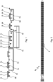
- FIG. 1 illustrates in a schematic representation an embodiment of the method according to the invention as well as the device according to the invention.
- a silicon substrate 10 which is provided with a phosphosilicate glass layer 12 on its entire surface, for example as a result of phosphorus diffusion, is transported by means of transport rollers in a transport direction 16 through a sequence of different tanks.
- a preconditioning tank 50 For this purpose, the underside 14 of the substrate 10 is wetted from below with a hydrophobizing liquid 52, in the present embodiment with an etching solution containing hydrofluoric acid.
- the preconditioning tank only plateau-free structure rollers 54 are provided as transport rollers, which enable homogeneous etching.
- the phosphosilicate glass layer 12 is evenly removed from the underside 14 and the edges 13.
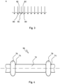
- FIG. 1 A side view of the embodiment of the Figure 1
- the plateauless structural rollers 54 used can be found in Figure 2 .
- An enlarged view of the partial area A is shown in Figure 3.
- deeply pierced recesses 80 can be seen, which are arranged directly adjacent to one another on the structural roller 54 and form raised areas. Walls 82 of two adjacent recesses 80 are arranged so close to one another that these raised areas do not have a plateau, but rather the shape of a tip 55.
- the plateau-less structural rollers 54 enable, as explained above, a homogeneous etching of the underside 14 of the substrate 10 in the preconditioning tank 50 with a comparatively low risk of undesirable local hydrophobization of the upper side 15 as a result of hydrophobizing liquid 52 being shoveled onto the upper side 15.
- the substrate 10 is transported into a rinsing basin 58, which contains deionized water 60 as a rinsing medium. There it is immersed in the deionized water 60, which serves as the rinsing liquid. The deionized water 60 is simultaneously used as a protective liquid.
- the substrate 10 is transported in the rinsing basin 58 by means of O-ring rollers 56, which minimize the contact surface for the substrate and thus enable an efficient rinsing process. Water 62 overflowing from the rinsing basin 58 is collected in an overflow basin 64.
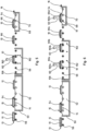
- a schematic representation of a section of the O-ring roller 56 shows Figure 4
- the O-ring roller 56 has a shaft element 72 and O-ring receptacles which are spaced apart from one another in the longitudinal direction of the shaft element 72 and which, in the case of the present example, are designed as recesses 74 in the shaft element 72, in each of which an O-ring 76 is arranged.
- the section of the O-ring roller 56 shown has two O-rings 76. This number is basically sufficient for transporting the flat substrate 10. Depending on requirements, for example in the case of larger or fragile substrates, a larger number of O-rings can be provided.
- the substrate 10 is transported further in the transport direction 16 by means of the O-ring shafts 56, it is The substrate 10 is then removed from the sink 58 in a horizontal manner.
- the O-ring rollers 56 are aligned accordingly for this purpose.
- the previously hydrophobicized edges 13 and the hydrophobicized underside 14 are free of deionized water 60 after the substrate 10 has been removed from the sink 58.
- the hydrophilic phosphosilicate glass layer 12 remaining on the upper side 15 of the substrate 10 additionally promotes the formation of the protective liquid film 66, whereby hydrophilicity in the present sense is understood to mean a contact angle between the surface and the wetting liquid of less than 15°.
- the hydrophilicity of the upper side 15 also counteracts the running down of deionized water from the protective liquid film 66.
- the substrate 10 is then transported into a treatment tank 60, which contains an etching solution 70.
- an etching solution 70 containing hydrofluoric acid and nitric acid is provided as the etching solution.
- an etching solution can be used which contains sulfuric acid in addition to hydrofluoric acid and nitric acid.
- the underside 14 is etched without the sensitive top side 15 of the substrate 10 being impaired.
- the running down of deionized water from the protective liquid film 66 or the creeping of etching solution 70 onto the upper side 15 of the substrate 10 is prevented. no streaks form on the underside 14 of the substrate 10 and the etching solution 70 is not contaminated or diluted by parts of the protective liquid film 66 running down from the top side 15 of the substrate 10.
- the advantages of the plateau-less structural rollers 54 described above also have a positive effect in the treatment tank, so that the risk of damage to the top side 15 of the substrate 10 is further reduced by the exclusive use of plateau-less structural rollers 54.
- the residence time of the substrates 10 in the preconditioning tank 50 must be selected such that the phosphosilicate glass layer 12 is reliably removed from the underside 14 of the substrate 10.
- the length of the preconditioning tank 50 must be adjusted accordingly if necessary.
- the substrates cannot be exposed to the hydrophobizing liquid 52 for an indefinite length of time. Otherwise, the hydrophobizing liquid 52 may creep onto the upper side 15 of the substrate 10 and cause considerable damage to this or the layers underneath.
- the residence time of the substrates in the preconditioning tank 50, or the length of this tank, must therefore be selected accordingly.
- Figure 5 illustrates in a schematic representation a second embodiment of the method according to the invention and the device according to the invention. This differs from the first embodiment of the Figure 1 by providing a sink 158 instead of the sink 58 which catches rinsing liquid.
- a surge pipe 160 is provided, by means of which the deionized water 60 used as rinsing liquid is applied to the top 15 of the silicon substrates.
- the deionized water 60 is applied in such an amount that water 162 dripping over the edges 13 of the silicon substrates 10 rinses the silicon substrates.
- a film of deionized water remains on the top 15 of the silicon substrates 10, which film is used as a protective liquid film 66. If rinsing of the substrates is not necessary, the deionized water or another suitable protective liquid can be applied to the upper side 15 of the silicon substrates 10 by means of the surge pipe 160 in such a metered manner that the protective liquid film 66 is formed, but only as little protective liquid as possible runs over the edges 13 of the silicon substrates 10 and drips into the rinsing basin 158.
- FIG. 6 illustrates in a schematic representation a third embodiment of the method according to the invention and the device according to the invention.
- This differs from the Figure 5 illustrated second embodiment, among other things, in that in addition to a surge pipe 160a, another surge pipe 160b is provided, which is arranged after the surge pipe 160a in the transport direction 16 of the substrates 10.
- the deionized water 60 is in turn applied to the substrates 10 as a protective liquid.
- the surge pipes 160a, 160b thus serve as application devices. Since they are arranged offset from one another in the transport direction 16 of the substrates, the deionized water 60 is applied several times as a protective liquid to the top side 15 of the substrates 10 by means of these surge pipes 160a, 160b.
- the deionized water 60 applied to the top side 15 of the substrates 10 by means of the surge pipe 160a forms a protective liquid film 66a, which in the respective application may not yet completely cover the top side 15 or may not yet have a sufficient thickness.
- the protective liquid film 66a may have formed islands, so that parts of the top side 15 are not covered with protective liquid or are not covered sufficiently.
- the multiple application of the protective liquid in this case the deionized water 60
- the protective liquid can result in a better distribution of the protective liquid in the corners of the substrates 10 and the edges of the substrates 10.
- the total amount of overflowing water 162 can be reduced by applying deionized water 60 or protective liquid several times. This enables a reduction in the effort required to carry out the process, particularly when using protective liquids other than water.
- FIG. 6 is another surge pipe 160c for applying the deionized water 60 to the Top side 15 of the substrates 10 is arranged above the treatment basin 68, and thus in the transport direction 16 of the substrates 10 after the rinsing basin 158.
- the surge pipe 160c like the surge pipes 160a and 160b, is intended to apply deionized water 60 as a protective liquid to the top side 15 of the substrates 10.
- FIG. 6 Three application devices for protective liquid are provided with the surge pipes 160a, 160b, 160c.
- one of these application devices preferably the surge pipe 160b or the surge pipe 160c, can be omitted.
- the remaining two surge pipes there are also several application devices arranged offset from one another in the transport direction 16 of the substrates 10, which enable repeated application of protective liquid, in this case deionized water 60, for the purpose of forming the protective liquid film.
- the protective liquid can be applied in such a metered manner that when protective liquid is applied to the upper side 15 of the substrate above the treatment tank 68, practically no protective liquid overflows and thus does not get into the etching solution 70, it has proven particularly advantageous to hold on to the surge pipe 160c, or more generally to an application device above the treatment tank 68.
- FIG. 6 The illustrated concept of several application devices arranged offset from one another in the transport direction 16 of the substrates 10 can be easily applied to the embodiment of Figure 1
- one or more application devices are provided after the rinsing basin, by means of which deionized water can be applied as a protective liquid to the upper side 15 of the substrates.
- the Figure 6 known surge pipes 160b or 160c or the like can be used.
- such a further application device could be arranged above the treatment tank 68 from Figure 1 be arranged.
Landscapes
- Weting (AREA)
- Cleaning By Liquid Or Steam (AREA)
- Cleaning Or Drying Semiconductors (AREA)
Claims (15)
- Procédé de traitement du côté inférieur d'un substrat plat (10) avec un milieu de traitement (70),
selon lequel- un côté inférieur (14) du substrat est hydrophobé au moyen d'une attaque chimique par voie humide d'un seul côté ;- un film de liquide de protection (66) est ensuite réalisé sur un côté supérieur (15) du substrat (10) ;- le milieu de traitement (70) est ensuite mis en contact avec le côté inférieur (14) du substrat (10) et le côté supérieur (15) est alors protégé au moyen du film de liquide de protection (66) contre une action du milieu de traitement (70) et/ou de ses dégagements gazeux. - Procédé selon la revendication 1, caractérisé en ce qu'un substrat de silicium (10) est traité et, en vue de l'hydrophobation du côté inférieur (14) du substrat de silicium (10), une couche de verre de silicate (12) est enlevée du côté inférieur (14) du substrat de silicium (10) .
- Procédé selon l'une quelconque des revendications précédentes, caractérisé en ce qu'en vue de la réalisation du film de liquide de protection (66), le substrat (10) est immergé dans un liquide de protection (60) et retiré de celui-ci ; lors du retrait du substrat (10) du liquide de protection (60), le substrat (10) étant orienté de telle sorte qu'il s'étend dans un plan essentiellement horizontal, de telle sorte que le film de liquide de protection (66) reste sur le côté supérieur (15) du substrat (10).
- Procédé selon l'une quelconque des revendications précédentes, caractérisé en ce qu'avant la réalisation du film de liquide de protection (66), les bords (13) du substrat sont hydrophobés, de préférence dans une étape de procédé commune avec l'hydrophobation du côté inférieur (14) du substrat (10).
- Procédé selon l'une quelconque des revendications précédentes, dans lequel le côté inférieur (14) du substrat (10) est hydrophobé au moyen d'une attaque chimique par voie humide d'un seul côté et, à cette fin, le substrat (10) est de préférence mouillé par le dessous avec un liquide d'attaque (52).
- Procédé selon la revendication 5, caractérisé en ce que- après l'attaque chimique par voie humide effectuée en vue de l'hydrophobation, un liquide de rinçage (60) est appliqué sur le substrat (10) en vue du rinçage,- la quantité de liquide de rinçage (60) appliquée sur le substrat (10) est choisie de telle sorte qu'au moins la moitié de la quantité de liquide de rinçage (162) appliquée s'égoutte du substrat (10), et- le liquide de rinçage restant sur le côté supérieur (15) du substrat (10) est utilisé en tant que film de liquide de protection (66).
- Procédé selon la revendication 3 et la revendication 5, caractérisé en ce qu'après l'attaque chimique par voie humide effectuée en vue de l'hydrophobation, le substrat (10) est immergé dans un liquide de rinçage (60) en vue du rinçage et ce liquide de rinçage (60) est utilisé simultanément en tant que liquide de protection (60), de telle sorte qu'un retrait du substrat (10) du liquide de rinçage (60) constitue simultanément le retrait du substrat (10) du liquide de protection (60).
- Procédé selon l'une quelconque des revendications précédentes, caractérisé en ce qu'un milieu d'attaque (70) est utilisé en tant que milieu de traitement (70) et le côté inférieur (14) du substrat (10) est attaqué au moyen de ce milieu d'attaque (70).
- Procédé selon l'une quelconque des revendications précédentes, caractérisé en ce qu'en vue de la réalisation du film de liquide de protection (66a, 66b, 66c, 66d), le liquide de protection (60) est appliqué plusieurs fois sur le côté supérieur (15) du substrat (10) .
- Dispositif pour la mise en œuvre du procédé selon l'une quelconque des revendications 1 à 9, présentant- un bassin de préconditionnement (50), lequel contient un liquide (52) hydrophobant les substrats (10) à traiter ;- un bassin de rinçage (58) agencé en aval du bassin de préconditionnement (50) dans une direction de transport (16) des substrats (10) ;- un bassin de traitement (68) agencé en aval du bassin de rinçage (58 ; 158) dans la direction de transport (16) des substrats (10), lequel contient un liquide de traitement (70) ;- des rouleaux de transport (54) agencés dans le bassin de préconditionnement (50) pour le transport des substrats (10) à travers le bassin de préconditionnement (50) ;des rouleaux de structure sans plateau (54) étant majoritairement, de préférence exclusivement, prévus dans le bassin de préconditionnement (50) en tant que rouleaux de transport (54).
- Dispositif selon la revendication 10, caractérisé en ce qu'il est prévu dans le bassin de rinçage (58 ; 158) pour le transport des substrats (10) à travers le bassin de rinçage (58), en majorité, de préférence exclusivement, des rouleaux à joint torique (56) en tant que rouleaux de transport, qui présentent chacun un élément d'arbre (72) ainsi que plusieurs logements de joint torique (74) espacés les uns des autres dans la direction longitudinale de l'élément d'arbre (72), un joint torique (76) étant agencé dans chacun desdits logements de joint torique (74), lequel entoure circonférentiellement l'élément d'arbre (72) ainsi que le logement de joint torique (74) respectif.
- Dispositif selon l'une quelconque des revendications 10 à 11, caractérisé en ce qu'il est prévu dans le bassin de traitement (68), pour le transport des substrats (10) à travers le bassin de traitement (68), majoritairement, de préférence exclusivement, des rouleaux de structure sans plateau (54) en tant que rouleaux de transport.
- Dispositif selon l'une quelconque des revendications 10 à 12, caractérisé en ce qu'il est prévu en tant que liquide d'attaque hydrophobant (52) une solution d'attaque (52) contenant de l'acide fluorhydrique et en ce qu'il est prévu en tant que liquide de traitement (70) une autre solution d'attaque (70) qui contient de l'acide fluorhydrique et un agent oxydant, de préférence de l'acide nitrique ou du peroxyde d'hydrogène.
- Dispositif selon l'une quelconque des revendications 10 à 13, caractérisé en ce que- plusieurs dispositifs d'application (160a, 160b, 160c) sont prévus, au moyen desquels un liquide de protection (60) peut être appliqué sur un côté supérieur (15) des substrats (10) ;- les plusieurs dispositifs d'application (160a, 160b, 160c) sont agencés en étant décalés les uns par rapport aux autres dans la direction de transport (16) des substrats (10) ;- au moins un des plusieurs dispositifs d'application (160a, 160b) est agencé au-dessus du bassin de rinçage (158) .
- Dispositif selon la revendication 14, caractérisé en ce qu'au moins un des plusieurs dispositifs d'application (160c) est agencé en aval du bassin de rinçage (158) dans la direction de transport (16) des substrats (10).
Applications Claiming Priority (2)
| Application Number | Priority Date | Filing Date | Title |
|---|---|---|---|
| DE102014117276.0A DE102014117276A1 (de) | 2014-11-25 | 2014-11-25 | Verfahren und Vorrichtung zur unterseitigen Behandlung eines Substrats |
| PCT/DE2015/100502 WO2016082826A1 (fr) | 2014-11-25 | 2015-11-24 | Procédé et dispositif pour le traitement de la face inférieure d'un substrat |
Publications (2)
| Publication Number | Publication Date |
|---|---|
| EP3224859A1 EP3224859A1 (fr) | 2017-10-04 |
| EP3224859B1 true EP3224859B1 (fr) | 2024-10-30 |
Family
ID=55273102
Family Applications (1)
| Application Number | Title | Priority Date | Filing Date |
|---|---|---|---|
| EP15830976.5A Active EP3224859B1 (fr) | 2014-11-25 | 2015-11-24 | Procédé et dispositif pour le traitement de la face inférieure d'un substrat |
Country Status (8)
| Country | Link |
|---|---|
| US (1) | US20170330780A1 (fr) |
| EP (1) | EP3224859B1 (fr) |
| JP (1) | JP6714592B2 (fr) |
| KR (1) | KR20170086556A (fr) |
| CN (1) | CN107112259A (fr) |
| DE (1) | DE102014117276A1 (fr) |
| TW (1) | TWI684214B (fr) |
| WO (1) | WO2016082826A1 (fr) |
Families Citing this family (4)
| Publication number | Priority date | Publication date | Assignee | Title |
|---|---|---|---|---|
| DE102015223227A1 (de) * | 2015-11-24 | 2017-05-24 | Rct Solutions Gmbh | Vorrichtung und Verfahren zur chemischen Behandlung eines Halbleiter-Substrats |
| CN106449395A (zh) * | 2016-11-14 | 2017-02-22 | 苏州宝馨科技实业股份有限公司 | 一种硅片的刻蚀方法及刻蚀设备 |
| CN112908905B (zh) * | 2020-12-08 | 2022-10-18 | 广东绿展科技有限公司 | 芯片刻蚀装置 |
| KR102856965B1 (ko) * | 2023-11-29 | 2025-09-11 | 주식회사 에스이에이 | 배기 유도 커버를 내부에 포함하는 기판 처리 장치 |
Citations (1)
| Publication number | Priority date | Publication date | Assignee | Title |
|---|---|---|---|---|
| US20100055398A1 (en) * | 2008-08-29 | 2010-03-04 | Evergreen Solar, Inc. | Single-Sided Textured Sheet Wafer |
Family Cites Families (10)
| Publication number | Priority date | Publication date | Assignee | Title |
|---|---|---|---|---|
| JPH08195334A (ja) * | 1994-11-17 | 1996-07-30 | Canon Inc | シリコン基板の接合方法 |
| KR101046287B1 (ko) * | 2004-03-22 | 2011-07-04 | 레나 게엠베하 | 기판 표면 처리 방법 |
| DE102006049488A1 (de) * | 2006-10-17 | 2008-04-30 | Höllmüller Maschinenbau GmbH | Vorrichtung zum Behandeln von flachen, zerbrechlichen Substraten |
| DE102008037404A1 (de) * | 2008-09-30 | 2010-04-01 | Schott Solar Ag | Verfahren zur chemischen Behandlung eines Substrats |
| WO2010041328A1 (fr) * | 2008-10-10 | 2010-04-15 | 有限会社マイスター | Rouleau applicateur |
| CN102714134B (zh) * | 2009-09-22 | 2016-01-13 | 雷纳有限公司 | 用于回蚀半导体层的方法和装置 |
| DE102009050845A1 (de) * | 2009-10-19 | 2011-04-21 | Gebr. Schmid Gmbh & Co. | Verfahren und Vorrichtung zur Behandlung einer Substratoberfläche eines Substrats |
| WO2012020274A1 (fr) * | 2010-08-10 | 2012-02-16 | Rena Gmbh | Procédé et appareil pour texturiser un substrat à semi-conducteur plat |
| CN103811583A (zh) * | 2012-11-12 | 2014-05-21 | 北京北方微电子基地设备工艺研究中心有限责任公司 | 一种硅片制绒方法及硅片制绒装置 |
| JP2014146753A (ja) * | 2013-01-30 | 2014-08-14 | Mitsubishi Electric Corp | 太陽電池用基板製造装置及びこれを用いた太陽電池用基板の製造方法 |
-
2014
- 2014-11-25 DE DE102014117276.0A patent/DE102014117276A1/de not_active Ceased
-
2015
- 2015-11-24 TW TW104138875A patent/TWI684214B/zh not_active IP Right Cessation
- 2015-11-24 WO PCT/DE2015/100502 patent/WO2016082826A1/fr not_active Ceased
- 2015-11-24 JP JP2017528957A patent/JP6714592B2/ja active Active
- 2015-11-24 US US15/529,791 patent/US20170330780A1/en not_active Abandoned
- 2015-11-24 EP EP15830976.5A patent/EP3224859B1/fr active Active
- 2015-11-24 CN CN201580063994.4A patent/CN107112259A/zh active Pending
- 2015-11-24 KR KR1020177016122A patent/KR20170086556A/ko not_active Ceased
Patent Citations (1)
| Publication number | Priority date | Publication date | Assignee | Title |
|---|---|---|---|---|
| US20100055398A1 (en) * | 2008-08-29 | 2010-03-04 | Evergreen Solar, Inc. | Single-Sided Textured Sheet Wafer |
Also Published As
| Publication number | Publication date |
|---|---|
| JP2017537477A (ja) | 2017-12-14 |
| TWI684214B (zh) | 2020-02-01 |
| JP6714592B2 (ja) | 2020-06-24 |
| DE102014117276A1 (de) | 2016-05-25 |
| EP3224859A1 (fr) | 2017-10-04 |
| WO2016082826A1 (fr) | 2016-06-02 |
| TW201631643A (zh) | 2016-09-01 |
| US20170330780A1 (en) | 2017-11-16 |
| KR20170086556A (ko) | 2017-07-26 |
| CN107112259A (zh) | 2017-08-29 |
Similar Documents
| Publication | Publication Date | Title |
|---|---|---|
| EP2232526B1 (fr) | Procédé et dispositif de traitement de tranches de silicium | |
| DE69012373T2 (de) | Verfahren und Vorrichtung zum Trocknen von Substraten nach Behandlung in einer Flüssigkeit. | |
| DE69530118T2 (de) | Reinigung von halbleitern unter ultraniedrigen partikelgehaltsbedingungen | |
| EP2517226B1 (fr) | Procédé et dispositif pour le traitement de substrats de silicium | |
| EP1733418B2 (fr) | Procédé d'isolation électrique des deux côtés de plaques de silicium par un traitement chimique unilatéral utilisant un bain de liquide | |
| EP2491584B2 (fr) | Procédé et dispositif de traitement de la surface d'un substrat | |
| EP3224859B1 (fr) | Procédé et dispositif pour le traitement de la face inférieure d'un substrat | |
| DE2229457B2 (de) | Verfahren zum Herstellen eines Halbleiterbauelements | |
| DE102007004060B4 (de) | Verwendung einer Ätzlösung aufweisend Wasser, Salpetersäure und Schwefelsäure und Ätzverfahren | |
| DE102014110222B4 (de) | Verfahren und Vorrichtung zur Strukturierung von Ober- und Unterseite eines Halbleitersubstrats | |
| WO2014023842A1 (fr) | Procédé de gravure alcaline | |
| DE112010003101B4 (de) | Verfahren zur Oberflächenbehandlung eines Wafers | |
| WO2019145485A1 (fr) | Procédé et dispositif pour traiter des surfaces gravées d'un substrat semi-conducteur faisant appel à un fluide contenant de l'ozone | |
| WO2017089302A1 (fr) | Dispositif et procédé de traitement chimique d'un substrat de semi-conducteur | |
| WO2016150788A1 (fr) | Dispositif et procédé de traitement chimique d'un substrat de semi-conducteur | |
| DE102011081327A1 (de) | Vorrichtung zur Oberflächenbehandlung von Substraten | |
| DE19936569B4 (de) | Herstellung von porösem Silicium | |
| DE102018206980A1 (de) | Verfahren und Vorrichtung zur Reinigung von geätzten Oberflächen eines Halbleitersubstrats | |
| WO2012113364A1 (fr) | Procédé de traitement d'un objet, notamment d'un substrat de cellule solaire, et dispositif permettant de réaliser ce procédé | |
| EP1010223A1 (fr) | Procede de traitement de substrats | |
| DE102008061521B4 (de) | Verfahren zur Behandlung einer Halbleiterscheibe | |
| DE202017102678U1 (de) | Transportrolle, Transportvorrichtung sowie Substratbehandlungsanlage | |
| DE102009028868A1 (de) | Verfahren zur Behandlung von Wafern mit einer Flüssigkeit in einer Nassbank | |
| DE102010006329A1 (de) | Verwendung einer Auftragswalze zum strukturierten Auftragen eines Ätz- oder Dotiermediums sowie Auftragswalze | |
| DE102013202138A1 (de) | Vorrichtung zur Substratnassbehandlung und Verwendung |
Legal Events
| Date | Code | Title | Description |
|---|---|---|---|
| STAA | Information on the status of an ep patent application or granted ep patent |
Free format text: STATUS: THE INTERNATIONAL PUBLICATION HAS BEEN MADE |
|
| PUAI | Public reference made under article 153(3) epc to a published international application that has entered the european phase |
Free format text: ORIGINAL CODE: 0009012 |
|
| STAA | Information on the status of an ep patent application or granted ep patent |
Free format text: STATUS: REQUEST FOR EXAMINATION WAS MADE |
|
| 17P | Request for examination filed |
Effective date: 20170623 |
|
| AK | Designated contracting states |
Kind code of ref document: A1 Designated state(s): AL AT BE BG CH CY CZ DE DK EE ES FI FR GB GR HR HU IE IS IT LI LT LU LV MC MK MT NL NO PL PT RO RS SE SI SK SM TR |
|
| AX | Request for extension of the european patent |
Extension state: BA ME |
|
| DAV | Request for validation of the european patent (deleted) | ||
| DAX | Request for extension of the european patent (deleted) | ||
| STAA | Information on the status of an ep patent application or granted ep patent |
Free format text: STATUS: EXAMINATION IS IN PROGRESS |
|
| 17Q | First examination report despatched |
Effective date: 20210514 |
|
| GRAP | Despatch of communication of intention to grant a patent |
Free format text: ORIGINAL CODE: EPIDOSNIGR1 |
|
| GRAP | Despatch of communication of intention to grant a patent |
Free format text: ORIGINAL CODE: EPIDOSNIGR1 |
|
| STAA | Information on the status of an ep patent application or granted ep patent |
Free format text: STATUS: GRANT OF PATENT IS INTENDED |
|
| INTG | Intention to grant announced |
Effective date: 20240614 |
|
| GRAS | Grant fee paid |
Free format text: ORIGINAL CODE: EPIDOSNIGR3 |
|
| GRAA | (expected) grant |
Free format text: ORIGINAL CODE: 0009210 |
|
| STAA | Information on the status of an ep patent application or granted ep patent |
Free format text: STATUS: THE PATENT HAS BEEN GRANTED |
|
| AK | Designated contracting states |
Kind code of ref document: B1 Designated state(s): AL AT BE BG CH CY CZ DE DK EE ES FI FR GB GR HR HU IE IS IT LI LT LU LV MC MK MT NL NO PL PT RO RS SE SI SK SM TR |
|
| REG | Reference to a national code |
Ref country code: GB Ref legal event code: FG4D Free format text: NOT ENGLISH |
|
| REG | Reference to a national code |
Ref country code: CH Ref legal event code: EP |
|
| REG | Reference to a national code |
Ref country code: DE Ref legal event code: R096 Ref document number: 502015016971 Country of ref document: DE |
|
| REG | Reference to a national code |
Ref country code: IE Ref legal event code: FG4D Free format text: LANGUAGE OF EP DOCUMENT: GERMAN |
|
| P01 | Opt-out of the competence of the unified patent court (upc) registered |
Free format text: CASE NUMBER: APP_63246/2024 Effective date: 20241128 |
|
| REG | Reference to a national code |
Ref country code: LT Ref legal event code: MG9D |
|
| REG | Reference to a national code |
Ref country code: NL Ref legal event code: MP Effective date: 20241030 |
|
| PG25 | Lapsed in a contracting state [announced via postgrant information from national office to epo] |
Ref country code: IS Free format text: LAPSE BECAUSE OF FAILURE TO SUBMIT A TRANSLATION OF THE DESCRIPTION OR TO PAY THE FEE WITHIN THE PRESCRIBED TIME-LIMIT Effective date: 20250228 Ref country code: HR Free format text: LAPSE BECAUSE OF FAILURE TO SUBMIT A TRANSLATION OF THE DESCRIPTION OR TO PAY THE FEE WITHIN THE PRESCRIBED TIME-LIMIT Effective date: 20241030 Ref country code: PT Free format text: LAPSE BECAUSE OF FAILURE TO SUBMIT A TRANSLATION OF THE DESCRIPTION OR TO PAY THE FEE WITHIN THE PRESCRIBED TIME-LIMIT Effective date: 20250228 |
|
| PG25 | Lapsed in a contracting state [announced via postgrant information from national office to epo] |
Ref country code: FI Free format text: LAPSE BECAUSE OF FAILURE TO SUBMIT A TRANSLATION OF THE DESCRIPTION OR TO PAY THE FEE WITHIN THE PRESCRIBED TIME-LIMIT Effective date: 20241030 Ref country code: NL Free format text: LAPSE BECAUSE OF FAILURE TO SUBMIT A TRANSLATION OF THE DESCRIPTION OR TO PAY THE FEE WITHIN THE PRESCRIBED TIME-LIMIT Effective date: 20241030 |
|
| PG25 | Lapsed in a contracting state [announced via postgrant information from national office to epo] |
Ref country code: BG Free format text: LAPSE BECAUSE OF FAILURE TO SUBMIT A TRANSLATION OF THE DESCRIPTION OR TO PAY THE FEE WITHIN THE PRESCRIBED TIME-LIMIT Effective date: 20241030 |
|
| PG25 | Lapsed in a contracting state [announced via postgrant information from national office to epo] |
Ref country code: ES Free format text: LAPSE BECAUSE OF FAILURE TO SUBMIT A TRANSLATION OF THE DESCRIPTION OR TO PAY THE FEE WITHIN THE PRESCRIBED TIME-LIMIT Effective date: 20241030 |
|
| PG25 | Lapsed in a contracting state [announced via postgrant information from national office to epo] |
Ref country code: NO Free format text: LAPSE BECAUSE OF FAILURE TO SUBMIT A TRANSLATION OF THE DESCRIPTION OR TO PAY THE FEE WITHIN THE PRESCRIBED TIME-LIMIT Effective date: 20250130 |
|
| PG25 | Lapsed in a contracting state [announced via postgrant information from national office to epo] |
Ref country code: LV Free format text: LAPSE BECAUSE OF FAILURE TO SUBMIT A TRANSLATION OF THE DESCRIPTION OR TO PAY THE FEE WITHIN THE PRESCRIBED TIME-LIMIT Effective date: 20241030 Ref country code: GR Free format text: LAPSE BECAUSE OF FAILURE TO SUBMIT A TRANSLATION OF THE DESCRIPTION OR TO PAY THE FEE WITHIN THE PRESCRIBED TIME-LIMIT Effective date: 20250131 |
|
| PG25 | Lapsed in a contracting state [announced via postgrant information from national office to epo] |
Ref country code: PL Free format text: LAPSE BECAUSE OF FAILURE TO SUBMIT A TRANSLATION OF THE DESCRIPTION OR TO PAY THE FEE WITHIN THE PRESCRIBED TIME-LIMIT Effective date: 20241030 |
|
| PG25 | Lapsed in a contracting state [announced via postgrant information from national office to epo] |
Ref country code: RS Free format text: LAPSE BECAUSE OF FAILURE TO SUBMIT A TRANSLATION OF THE DESCRIPTION OR TO PAY THE FEE WITHIN THE PRESCRIBED TIME-LIMIT Effective date: 20250130 |
|
| REG | Reference to a national code |
Ref country code: CH Ref legal event code: PL |
|
| PG25 | Lapsed in a contracting state [announced via postgrant information from national office to epo] |
Ref country code: SM Free format text: LAPSE BECAUSE OF FAILURE TO SUBMIT A TRANSLATION OF THE DESCRIPTION OR TO PAY THE FEE WITHIN THE PRESCRIBED TIME-LIMIT Effective date: 20241030 |
|
| PG25 | Lapsed in a contracting state [announced via postgrant information from national office to epo] |
Ref country code: MC Free format text: LAPSE BECAUSE OF FAILURE TO SUBMIT A TRANSLATION OF THE DESCRIPTION OR TO PAY THE FEE WITHIN THE PRESCRIBED TIME-LIMIT Effective date: 20241030 |
|
| PG25 | Lapsed in a contracting state [announced via postgrant information from national office to epo] |
Ref country code: DK Free format text: LAPSE BECAUSE OF FAILURE TO SUBMIT A TRANSLATION OF THE DESCRIPTION OR TO PAY THE FEE WITHIN THE PRESCRIBED TIME-LIMIT Effective date: 20241030 |
|
| PG25 | Lapsed in a contracting state [announced via postgrant information from national office to epo] |
Ref country code: LU Free format text: LAPSE BECAUSE OF NON-PAYMENT OF DUE FEES Effective date: 20241124 |
|
| REG | Reference to a national code |
Ref country code: CH Ref legal event code: PL |
|
| PG25 | Lapsed in a contracting state [announced via postgrant information from national office to epo] |
Ref country code: EE Free format text: LAPSE BECAUSE OF FAILURE TO SUBMIT A TRANSLATION OF THE DESCRIPTION OR TO PAY THE FEE WITHIN THE PRESCRIBED TIME-LIMIT Effective date: 20241030 |
|
| PG25 | Lapsed in a contracting state [announced via postgrant information from national office to epo] |
Ref country code: CH Free format text: LAPSE BECAUSE OF NON-PAYMENT OF DUE FEES Effective date: 20241130 |
|
| PG25 | Lapsed in a contracting state [announced via postgrant information from national office to epo] |
Ref country code: RO Free format text: LAPSE BECAUSE OF FAILURE TO SUBMIT A TRANSLATION OF THE DESCRIPTION OR TO PAY THE FEE WITHIN THE PRESCRIBED TIME-LIMIT Effective date: 20241030 |
|
| PG25 | Lapsed in a contracting state [announced via postgrant information from national office to epo] |
Ref country code: SK Free format text: LAPSE BECAUSE OF FAILURE TO SUBMIT A TRANSLATION OF THE DESCRIPTION OR TO PAY THE FEE WITHIN THE PRESCRIBED TIME-LIMIT Effective date: 20241030 |
|
| PG25 | Lapsed in a contracting state [announced via postgrant information from national office to epo] |
Ref country code: CZ Free format text: LAPSE BECAUSE OF FAILURE TO SUBMIT A TRANSLATION OF THE DESCRIPTION OR TO PAY THE FEE WITHIN THE PRESCRIBED TIME-LIMIT Effective date: 20241030 |
|
| PG25 | Lapsed in a contracting state [announced via postgrant information from national office to epo] |
Ref country code: IT Free format text: LAPSE BECAUSE OF FAILURE TO SUBMIT A TRANSLATION OF THE DESCRIPTION OR TO PAY THE FEE WITHIN THE PRESCRIBED TIME-LIMIT Effective date: 20241030 |
|
| REG | Reference to a national code |
Ref country code: DE Ref legal event code: R097 Ref document number: 502015016971 Country of ref document: DE |
|
| REG | Reference to a national code |
Ref country code: BE Ref legal event code: MM Effective date: 20241130 |
|
| PLBE | No opposition filed within time limit |
Free format text: ORIGINAL CODE: 0009261 |
|
| STAA | Information on the status of an ep patent application or granted ep patent |
Free format text: STATUS: NO OPPOSITION FILED WITHIN TIME LIMIT |
|
| PG25 | Lapsed in a contracting state [announced via postgrant information from national office to epo] |
Ref country code: SE Free format text: LAPSE BECAUSE OF FAILURE TO SUBMIT A TRANSLATION OF THE DESCRIPTION OR TO PAY THE FEE WITHIN THE PRESCRIBED TIME-LIMIT Effective date: 20241030 |
|
| GBPC | Gb: european patent ceased through non-payment of renewal fee |
Effective date: 20250130 |
|
| 26N | No opposition filed |
Effective date: 20250731 |
|
| PG25 | Lapsed in a contracting state [announced via postgrant information from national office to epo] |
Ref country code: GB Free format text: LAPSE BECAUSE OF NON-PAYMENT OF DUE FEES Effective date: 20250130 Ref country code: BE Free format text: LAPSE BECAUSE OF NON-PAYMENT OF DUE FEES Effective date: 20241130 |
|
| PG25 | Lapsed in a contracting state [announced via postgrant information from national office to epo] |
Ref country code: FR Free format text: LAPSE BECAUSE OF NON-PAYMENT OF DUE FEES Effective date: 20241230 |
|
| PG25 | Lapsed in a contracting state [announced via postgrant information from national office to epo] |
Ref country code: IE Free format text: LAPSE BECAUSE OF NON-PAYMENT OF DUE FEES Effective date: 20241124 |
|
| REG | Reference to a national code |
Ref country code: DE Ref legal event code: R079 Ref document number: 502015016971 Country of ref document: DE Free format text: PREVIOUS MAIN CLASS: H01L0021670000 Ipc: H10P0072000000 |
|
| PGFP | Annual fee paid to national office [announced via postgrant information from national office to epo] |
Ref country code: DE Payment date: 20251118 Year of fee payment: 11 |
|
| PG25 | Lapsed in a contracting state [announced via postgrant information from national office to epo] |
Ref country code: AT Free format text: LAPSE BECAUSE OF NON-PAYMENT OF DUE FEES Effective date: 20241124 |
|
| REG | Reference to a national code |
Ref country code: AT Ref legal event code: MM01 Ref document number: 1737801 Country of ref document: AT Kind code of ref document: T Effective date: 20241124 |