EP3225105B1 - Amélioration de la détermination de proximité de balise rf - Google Patents
Amélioration de la détermination de proximité de balise rf Download PDFInfo
- Publication number
- EP3225105B1 EP3225105B1 EP17162289.7A EP17162289A EP3225105B1 EP 3225105 B1 EP3225105 B1 EP 3225105B1 EP 17162289 A EP17162289 A EP 17162289A EP 3225105 B1 EP3225105 B1 EP 3225105B1
- Authority
- EP
- European Patent Office
- Prior art keywords
- collar
- beacon
- data
- receiver
- distance
- Prior art date
- Legal status (The legal status is an assumption and is not a legal conclusion. Google has not performed a legal analysis and makes no representation as to the accuracy of the status listed.)
- Active
Links
Images








Classifications
-
- H—ELECTRICITY
- H04—ELECTRIC COMMUNICATION TECHNIQUE
- H04W—WIRELESS COMMUNICATION NETWORKS
- H04W4/00—Services specially adapted for wireless communication networks; Facilities therefor
- H04W4/02—Services making use of location information
-
- G—PHYSICS
- G01—MEASURING; TESTING
- G01S—RADIO DIRECTION-FINDING; RADIO NAVIGATION; DETERMINING DISTANCE OR VELOCITY BY USE OF RADIO WAVES; LOCATING OR PRESENCE-DETECTING BY USE OF THE REFLECTION OR RERADIATION OF RADIO WAVES; ANALOGOUS ARRANGEMENTS USING OTHER WAVES
- G01S1/00—Beacons or beacon systems transmitting signals having a characteristic or characteristics capable of being detected by non-directional receivers and defining directions, positions, or position lines fixed relatively to the beacon transmitters; Receivers co-operating therewith
- G01S1/02—Beacons or beacon systems transmitting signals having a characteristic or characteristics capable of being detected by non-directional receivers and defining directions, positions, or position lines fixed relatively to the beacon transmitters; Receivers co-operating therewith using radio waves
- G01S1/68—Marker, boundary, call-sign, or like beacons transmitting signals not carrying directional information
-
- A—HUMAN NECESSITIES
- A01—AGRICULTURE; FORESTRY; ANIMAL HUSBANDRY; HUNTING; TRAPPING; FISHING
- A01K—ANIMAL HUSBANDRY; AVICULTURE; APICULTURE; PISCICULTURE; FISHING; REARING OR BREEDING ANIMALS, NOT OTHERWISE PROVIDED FOR; NEW BREEDS OF ANIMALS
- A01K11/00—Marking of animals
- A01K11/006—Automatic identification systems for animals, e.g. electronic devices, transponders for animals
-
- A—HUMAN NECESSITIES
- A01—AGRICULTURE; FORESTRY; ANIMAL HUSBANDRY; HUNTING; TRAPPING; FISHING
- A01K—ANIMAL HUSBANDRY; AVICULTURE; APICULTURE; PISCICULTURE; FISHING; REARING OR BREEDING ANIMALS, NOT OTHERWISE PROVIDED FOR; NEW BREEDS OF ANIMALS
- A01K15/00—Devices for taming animals, e.g. nose-rings or hobbles; Devices for overturning animals in general; Training or exercising equipment; Covering boxes
- A01K15/02—Training or exercising equipment, e.g. mazes or labyrinths for animals ; Electric shock devices; Toys specially adapted for animals
- A01K15/021—Electronic training devices specially adapted for dogs or cats
-
- G—PHYSICS
- G01—MEASURING; TESTING
- G01S—RADIO DIRECTION-FINDING; RADIO NAVIGATION; DETERMINING DISTANCE OR VELOCITY BY USE OF RADIO WAVES; LOCATING OR PRESENCE-DETECTING BY USE OF THE REFLECTION OR RERADIATION OF RADIO WAVES; ANALOGOUS ARRANGEMENTS USING OTHER WAVES
- G01S11/00—Systems for determining distance or velocity not using reflection or reradiation
- G01S11/02—Systems for determining distance or velocity not using reflection or reradiation using radio waves
- G01S11/06—Systems for determining distance or velocity not using reflection or reradiation using radio waves using intensity measurements
-
- H—ELECTRICITY
- H04—ELECTRIC COMMUNICATION TECHNIQUE
- H04L—TRANSMISSION OF DIGITAL INFORMATION, e.g. TELEGRAPHIC COMMUNICATION
- H04L67/00—Network arrangements or protocols for supporting network services or applications
- H04L67/01—Protocols
- H04L67/12—Protocols specially adapted for proprietary or special-purpose networking environments, e.g. medical networks, sensor networks, networks in vehicles or remote metering networks
-
- H—ELECTRICITY
- H04—ELECTRIC COMMUNICATION TECHNIQUE
- H04L—TRANSMISSION OF DIGITAL INFORMATION, e.g. TELEGRAPHIC COMMUNICATION
- H04L67/00—Network arrangements or protocols for supporting network services or applications
- H04L67/50—Network services
- H04L67/52—Network services specially adapted for the location of the user terminal
-
- H—ELECTRICITY
- H04—ELECTRIC COMMUNICATION TECHNIQUE
- H04W—WIRELESS COMMUNICATION NETWORKS
- H04W4/00—Services specially adapted for wireless communication networks; Facilities therefor
- H04W4/80—Services using short range communication, e.g. near-field communication [NFC], radio-frequency identification [RFID] or low energy communication
Definitions
- US 2012/000431 discloses an electronic pet containment system for selectively providing access to a site within a control area.
- the system comprises: (i) a site unit assigned to a site within the control area; (ii) a pet unit assigned to a pet, the pet unit including: a pet unit stimulus device, a pet unit transceiver module operable to generate a signal utilized to calculate a measured distance between the pet unit and the site unit, and a pet unit processor programmed to selectively activate the pet unit stimulus device.
- the pet unit is configured to operate in a first electronic mode, in which the pet unit is not electronically paired with the site unit, and in a second electronic mode, in which the pet unit is electronically paired with the site unit; and the pet unit processor activates the pet unit stimulus device when: (a) the pet unit is paired with the site unit, and (b) the measured distance is equal to or less than a predetermined reference distance.
- the invention discloses a system for improving the distance assessment between a transmitter and a receiver making use of multiple distance measurement techniques.
- the invention is defined by the claims.
- the present invention disclosed herein provides a system for estimating distance from a receiver to a communications device, as defined in claims 1 to 15, which can be used for example, as a monitoring/tracking/detection/training/avoidance system for pets.
- the present disclosure provides for the simple set up of such systems, easy configuration of system components, and optionally worldwide, real-time access to the information.
- the systems and methods described herein include distributing pet beacons in a house at strategic locations to provide monitoring/tracking/detecting/training/avoidance functionality for pets.
- These devices are designed to periodically transmit a unique identification code along with functional parameters.
- Currently, such devices transmit signals for a distance of up to 70 meters. They are designed to be either battery or line powered, are small and easily located anywhere in the home.
- the individual beacons do not have an assigned function under one embodiment. This allows for simple activation and placement. Under one embodiment, beacons send unique identification and health status only (i.e. battery life). Under alternative embodiments, beacons may also transmit minimum and maximum signal strength values and other functional parameters.
- the systems and methods described herein include providing pet collar devices.
- a pet wears a collar that is designed to receive beacon transmissions, and act upon and/or store the data transmissions.
- Pet collar devices may also transmit beacon configuration data and summarized collected data from all monitored beacons to one or more smartphone receivers.
- the collar is also capable of providing positive and negative reinforcement as necessary utilizing a number of different stimulation techniques.
- beacons comprise Bluetooth® Low Energy beacons.
- beacons comprise Bluetooth Low Energy peripherals capable of RF connection.
- collars may comprise Bluetooth low energy enabled devices that function in a manner analogous to beacons.
- Bluetooth low energy (BLE) is itself a wireless technology standard for personal area networks. BLE is targeted for very low power devices, i.e. devices that can run on a coin cell battery for months or years.
- Bluetooth enabled beacons/devices may comprise Bluetooth integrated circuit implementations. Updates to embedded code of a Bluetooth enabled device may be accomplished through firmware over the air upgrades.
- Mobile device operating systems may natively support the Bluetooth low energy wireless communications protocol. Such operating systems include iOS, Android, Windows Phone and BlackBerry, as well as OS X, Linux, and Windows 8.
- a smartphone application is described herein that is used to set up, and configure the in-home detection/monitoring system and configure its components.
- the smartphone application may also be used to monitor and control beacons and/or collar devices and upload monitored data.
- the smart phone application when in range of either a beacon or a collar device may receive data from such devices, collect the data and/or store the data.
- the smart phone application may also cause action by a device such as the collar or any beacon, manually or automatically.
- the application may wirelessly signal the collar device to apply a corrective action, i.e. apply a stimulus to the corresponding pet.
- the application may provide a simple user interface for configuring the system, its components and their functionality.
- beacons, the pet collar device(s) and mobile devices may both transmit and receive data. Accordingly, each such component/device may serve a dual function of transmitting and receiving/collecting data as further described below.
- beacons and pet collar devices are Bluetooth enabled but embodiments are not so limited.
- an operating system of a mobile device running a smartphone application of the system described herein natively supports Bluetooth communications. Such operating system also natively supports any other communications protocols as they become available.
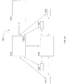
- Figure 1 shows a home premises featuring a plurality of beacons 110-170 distributed by owner/user throughout the premises.
- Figure 1 shows a beacon 120 placed in a bathroom of the home.
- Figure 1 shows a beacon 130 placed in a bedroom of the home.
- Figure 1 shows a beacon 110 placed at a front door of the home.
- Figure 1 shows a beacon 140 placed at a living room window of the home.
- a beacon 170 may also be placed in a kitchen of the home.
- beacon 160 it is of course possible to place a beacon just about anywhere in, or around, the premises including in proximity to the pet's bed (beacon 160 ), food/water bowl (beacon 150 ) or other locations that may require monitoring, e.g. pet doors, furniture, outlets, etc.
- the dotted circles indicate the RF energy emitted from each beacon.
- a solid circle 190 indicates a range or threshold distance from each beacon configured be an "action" or "threshold” distance as further described below.
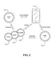
- Figure 2 shows the components of a monitoring/tracking/detection system under an embodiment.
- Figure 2 shows mobile device 210 running a smartphone application.
- the smartphone application is communicatively coupled to collar devices 220, 230.
- the smartphone application may transmit data to and control certain functions of the collar devices 220, 230 as further described below.
- the smartphone application may also receive data from collar devices as further described below.
- Figure 2 shows collar devices 220, 230 communicatively coupled to beacons 240, 250, 260.
- the collar devices receive data periodically transmitted by beacons 240, 250, 260 and otherwise communicate with beacons 240, 250, 260 as further described below.
- the smartphone application 210 may assign certain functionality directly to beacons 240, 250, 260 and otherwise communicates with beacons as further described below.
- a Bluetooth enabled beacon periodically transmits data including a unique identification number.
- a Bluetooth enabled device e.g. the collar device described herein, receives the periodically transmitted data, extracts the identification number and estimates the transmission's signal strength (i.e. received signal strength indication or "RSSI"). The collar device then uses the signal strength to estimate a distance from collar device to the transmitting beacon. The collar may be further assisted with its ranging calculation by utilizing calibration data contained within the beacon message. Further, the collar device itself periodically transmits data including a unique identification number. Under one embodiment, the collar device cycles between "transmission" and "listening" modes.
- the collar device may periodically transmit data during a "transmission” period and then simply receive incoming signals from in range beacons/devices during a “listening” period.
- the collar may shift between "transmission” and “listening” periods in five second intervals.
- beacons similarly shift between transmission and listening modes.
- the smartphone application may provide an "easy to use" configuration interface.
- a pet owner may initiate the application on a smartphone and walk through a set up procedure using the configuration interface.
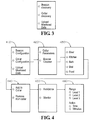
- such interface of the application may provide click through buttons for "beacon” and "collar” discovery modes as seen in Figure 3 .
- the user may under this embodiment select "beacon” discovery mode.
- the interface may then prompt the user to bring the smartphone device in proximity to a transmitting beacon, i.e. within transmission range of a beacon.
- beacon discovery mode the application may use one or more mobile device operating system APIs to detect incoming Bluetooth transmissions.
- the application and mobile device detect the periodically transmitted beacon signal and identify/store its unique identification number.
- the mobile device may use strength of incoming signal to estimate a distance from the beacon.
- the application may only enable availability of discovery mode in close proximity to the transmitting beacon. The user may repeat this process for each and every beacon that the user wishes to deploy in the premises. In this manner, the application learns the identification number of each beacon deployed in the premises
- a user runs the same application on the user's smart phone to configure the collar device for operation.
- an interface of the application may provide click through buttons for "beacon” and "collar” discovery modes as seen in Figure 3 .
- the user may under this embodiment select the "collar” discovery mode.
- the user brings the smartphone device in proximity to the pet collar device, i.e. within transmission range of the collar.
- the application may use one or more mobile device operating system APIs to detect incoming Bluetooth transmissions originating from the collar device.
- the application and mobile device detect the periodically transmitted signals from the collar device and identify its unique identification number.
- the mobile device may use strength of incoming signal to estimate a distance from the collar device.
- the application may only enable availability of collar device discovery mode in close proximity to the collar device. The user may repeat this process for each and every collar device that the user wishes to deploy in the premises. In this manner, the application learns the identification number of each collar device deployed in the premises.
- Figure 3 provides a separate interface for discovery of beacons and collar devices.
- the discovery mode interface may be integrated into the workflow of beacon/collar configuration interfaces shown in Figures 4 and 6 and further described below.
- Figure 3 provides Upload Monitor Data allowing the option to trigger upload of data collected by collar device to the smartphone.
- a user may use the smartphone application to configure the collar (or collars) for operation, i.e. to configure "collar defined” functions or enable recognition of specific "tag defined” beacons.
- the collar itself performs a set of “active” and/or “passive” functions. Proximity to a beacon triggers one or more such functions as defined by the user with respect to the particular beacon. In other word, for each deployed beacon the user defines a collar implemented function triggered by the collar's entry into a defined proximity of a particular beacon.
- FIG. 4 shows an interface allowing a user to configure collar defined functions with respect to specific beacons.
- This system of this embodiment comprises a single collar and multiple beacons.
- Screen 410 shows a Beacon Configuration option (described below with respect to Figure 6 ), a Collar Configuration option, and an Upload Monitor Data option.
- the Upload Monitor Data Option of screen 410 provides the option to trigger upload of data collected by collar device to the smartphone).
- a user selects under one embodiment the Collar Configuration option and is presented with screen 420. At this screen 420 a user may select Collar Parameters or Beacon Chooser.
- the Collar Parameters option introduces an interface (not shown) for configuring functional parameters of the collar such as correction level.
- a user selects under an embodiment Beacon Chooser and proceeds to screen 430 which lists the beacons available within the system (e.g. door, kitchen, bath, bed, food).
- the user selects the kitchen beacon and is provided a choice at screen 440 between Add to Collar and Remove from Collar.
- the user may select Add to Collar to associate the kitchen beacon with the collar device. (The user may also select Remove from Collar to dissociate from the collar device a previously assigned beacon).
- the user sees screen 450 featuring Avoidance and Monitor options.
- a user may assign the kitchen beacon an Avoidance function or a Monitor function.
- the user manipulates interface selections (at screen 460 ) to assign the collar a stimulus function when the collar is within a selected range (Level 1) of the beacon. Specifically the user selects a negative stimulus (applied by the collar) as an avoidance function and designates a corresponding range.
- the application interface may provide various stimulus functions (tone, stimulus, scent, etc.) and one or more ranges. Range Level 1 for example indicates close proximity to a beacon. Range Level 2 and Range Level 3 represent enlarged threshold distances.
- the user may be presented with another screen (not shown) allowing user to designate permitted access times, e.g. times during which the collar does not apply the designated function when the collar device in within the designated range.
- Embodiments are not limited to the functions and ranges described in Figure 4 .
- the user simply directs the collar to perform an avoidance function when the collar is within a near range threshold distance of the beacon.
- the application may prompt the user to bring the application in proximity to the collar device.
- the application may then transmit such configuration data to the pet collar device which uses the data to build/maintain a database which associates actions/functions with beacons (and corresponding unique identification numbers and permitted times). In this manner a user may assign functions to the collar with respect to each beacon within the system.
- Figure 5 shows a representative entry in a database which associates beacon identification number 510 with an avoidance function 530 and threshold distance 520.
- the representative database entry also includes start time 540 / end time 550 of the configured function.
- Such database may associate values using a relational database scheme.
- an operational pet collar device approaches the particular beacon and crosses over the configured threshold distance.
- the particular beacon simply transmits is unique identification number.
- the collar device receives the signal, identifies the unique identification number, and uses signal strength of the transmission to estimate a distance to the beacon.
- the collar device uses the identification number to perform a database lookup to determine the assigned collar function with respect to the beacon (e.g., a negative stimulus) and conditions for its performance (e.g. location of the collar device within a certain threshold distance and permitted time of performance).
- the collar determines that the function is delivery of stimulus and also resolves that the estimated distance from collar to beacon is less than the selected threshold distance (via comparison of estimated distance with designated threshold distance). Therefore, the collar device delivers the avoidance stimulus to the pet wearing the collar device.
- threshold distance may comprise distance from a location or a range of such distances (including an upper and lower boundary).
- the assigned function comprises a user/collar defined function.
- a user may assign functions to collar/beacon combinations. For example, a user may wish to prevent a pet from jumping on the user's couch. Therefore, the user may assign a beacon located near the couch an avoidance function, i.e. assign an avoidance function to a collar with respect to such beacon. However, a user may simply wish to know how often a pet visits a water bowl in daytime hours while the user is away from the premises, i.e. the user may simply wish to track the location of a pet. Accordingly, a user may assign a beacon located near the water bowl a tracking function, i.e. assign a tracking function to a collar with respect to such beacon.
- the pet collar device When the pet collar device is within a threshold distance of the beacon (and once the collar device processes conditions for performance of the assigned function based on beacon/function/distance/time parameters), the pet collar device simply logs location data, e.g. the occurrence of a threshold crossing, the time of a threshold crossing, duration of pet's proximity to a beacon, etc.).
- the tracking beacon may under an embodiment also administer a positive reinforcement such as a positive tone if so configured by the user.
- the configuration process described above may be used to assign functions to a second collar device with respect to the same set of beacons. This set of functions may be entirely different than those assigned to the first collar. This is possible due to the fact that beacons merely transmit identification numbers while the collar devices detect/extract the identification numbers and then resolve/perform a user defined function based on configuration data stored in a collar specific database.
- a user may also dedicate a specific beacon to a particular task. For example, a user may use the application interface during setup to assign an avoidance function to a beacon directly.
- An example of directly configuring a beacon defined function using a smartphone application is provided below.
- a user initiates the smartphone application which under one embodiment provides an interface for assignment of functions directly to beacons.
- Figure 6 shows a screen 610 featuring Beacon and Collar Configuration options as well as a Monitor Data option.
- a user may select the Beacon Configuration option shown in Figure 6 .
- the interface may then present at the next screen 620 all discovered beacons, i.e. up to "n" number beacons discovered via the process described above and as seen in Figure 6 .
- Beacons 1-n may be replaced by the names of the monitored locations, e.g. kitchen, door, window, etc.).
- a user selects a particular beacon (e.g. beacon 2) and then views configuration options at screen 630 for the pet collar with respect to the selected beacon.
- Screen 630 shows Avoidance and Monitor options which represent options to assign an Avoidance or Monitor function to the beacon.
- the Collar Defined option provides the option to designate a beacon as collar defined which means that the beacon's interaction with a collar device is governed by configuration data maintained by the collar device as described above with respect to Figure 4 ).
- the user may under an embodiment designate an Avoidance function at screen 630.
- the user is then presented at screen 640 with range and action options as seen in Figure 6 .
- the user manipulates interface selections to assign the collar a stimulus function when the collar is within a selected range (Level 1) of the beacon. Specifically the user selects a negative stimulus (applied by the collar) as an avoidance function and designates a corresponding range.
- the application interface may provide various stimulus functions (tone, stimulus, scent, etc.) and one or more ranges. Range Level 1 for example indicates close proximity to a beacon. Range Level 2 and Range Level 3 represent enlarged threshold distances. After selecting range and function, the user may be presented with another screen (not shown) allowing user to designate permitted access times, e.g. times during which the collar does not apply the designated function when the collar device in within the designated range.
- Embodiments are not limited to the functions and ranges described in Figure 6 .
- the application may prompt the user to bring the application in proximity to the beacon.
- the application may then transmit such configuration data (including function data, distance data, and permitted times data) to the beacon.
- the beacon encodes the particular configuration data into packets for inclusion in the beacon's periodic transmissions. Accordingly, the beacon periodically transmits both its identification number and the configuration data to devices within its range. In this manner a user may assign a function directly to each beacon within the system.
- the application also transmits the unique identification number of the particular configured beacon to the collar device. In this manner, the collar device may monitor incoming beacon transmissions and confirm that the beacon is part of the configured system under this embodiment.
- a user may use the application interface during setup to assign an avoidance function to a beacon directly.
- the application transmits such configuration data to the specifically tasked beacon.
- beacons not only transmit data, they may also receive and store data from other beacons or devices.
- the transmitted data includes "function data" (which encodes the particular function in data packets for inclusion in the beacon's periodic transmissions), threshold distance (and permitted time data under an embodiment).
- the application may also send the beacon's identification number to the collar device which stores such information. Accordingly, the beacon periodically transmits its identification number, the function data, and a threshold distance (and permitted times under an embodiment) to devices within its range. Under this example, the pet collar device may approach the beacon transmitting the identification number and corresponding data.
- the collar device then extracts the identification number, the "function data", distance data (and permitted time data under an embodiment) and uses the signal strength of the transmission to estimate distance from the beacon.
- the collar device may match the identification number to stored beacon identification numbers to ensure that the particular beacon is part of the configured system, i.e., that the collar device should proceed.
- the collar device may then match "function data" with function type, e.g. avoidance, tracking, etc., using embedded code within a pet collar.
- a smartphone application may transmit such data to the collar device during set up operations.
- the function data corresponds to an avoidance task, i.e. delivery of negative stimulus.
- the collar device resolve whether the device is within the designated threshold distance (and within appropriate time interval under an embodiment). If so, the collar device executes the assigned function, i.e. delivers the negative stimulus.
- Figure 7A shows a beacon defined embodiment of beacon/device functionality.
- the beacon 710 transmits 720 its identification number, a distance range (e.g., nearby range) and function data.
- distance range may comprise distance from a location or a range of such distances including an upper and lower boundary.
- the collar devices uses signal strength to estimate distance from the transmitting beacon.
- the collar device 730 extracts function data (corresponding to negative stimulus) and distance range information from the signal.
- the collar device interprets the function data as a negative stimulus function, and if the collar device determines that the collar device is within a near range distance, then the collar device applies the negative stimulus.
- the collar device may also log the time/duration of the event along with corresponding identification number of the beacon.
- Figure 7B shows a collar defined embodiment of beacon/device functionality.
- the beacon 740 located near a couch
- the collar device 760 detects the transmission, identifies the identification number and uses signal strength to estimate distance from the transmitting beacon.
- the collar device uses the identification number to look up configuration data.
- such data comprises an avoidance function (i.e., negative stimulus), and a midrange distance.
- avoidance function i.e., negative stimulus
- distance range may comprise distance from a location or a range of such distances including an upper and lower boundary. If the collar device determines that the device is within a midrange distance, then the collar device applies the negative stimulus.
- the collar device may also log the time/duration of the event along with corresponding identification number of the beacon.
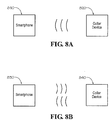
- Figure 8A shows a collar device 820 transmitting data to a smartphone 810 under one embodiment.
- Figure 8B shows two way communication between a collar device 840 and a smartphone 830 under one embodiment.
- a home detection kit may ship with a collar and corresponding beacons.
- a user may first register the smart phone application with a company provided internet service. Registration may provide the application with the unique device identification numbers of the beacons and the collar(s). Alternatively, the application may discover identification numbers during configuration as described in detail above.
- a pet owner/user deploys beacons in a home.
- the user simply locates beacons in areas of interest.
- the pet owner uses a collar, in conjunction with a smartphone application to assign "Avoid” and/or “Track” functions to collar/beacon combinations.
- assigning an "Avoid” function using the procedures already described in detail above
- a user first places a red sticker on a beacon.
- the user then approaches the beacon with a mobile device running the smartphone application.
- the application/device reads the unique identification of the beacon and reads receiver signal strength indication (RSSI) value.
- RSSI receiver signal strength indication
- the application then communicates with the collar to assign collar a function of the particular beacon when the pet collar is within a set range of the beacon. If the pet collar comes within a configured distance of the particular beacon, the collar triggers a negative stimulus and stores the time of the event under an embodiment.
- a user first places a green sticker on beacon.
- the user then approaches the beacon with a mobile device running the smartphone application.
- the application/device reads the unique identification of the beacon and reads receiver signal strength indication (RSSI) value.
- RSSI receiver signal strength indication
- the application then communicates with the collar to assign collar a function of the particular beacon when the pet collar is within a set range of the beacon. If the pet collar comes within a configured distance of the particular beacon, the collar will log the occurrence of the event and/or emit a positive reinforcement stimulus under an embodiment.
- the collar may also store the time of the event.
- the collar collects data while controlling the pet's whereabouts through stimulus events triggered by proximity to "red” beacons and tracked events triggered by proximity to "green” beacons.
- the collar transmits all collected/queued data to the application which may then display such information.
- a user may also deliver immediate Avoid/Track commands to the collar.
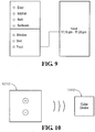
- Figure 9 shows an application interface allowing user a selection among beacon locations.
- a user may select "Food” which then directs user to another page featuring tracking data.
- the interface shows that the user's pet was within a configured range of the pet's water bowl from 11:15-11:20pm.
- Figure 10 shows a "Remote Trainer" interface page of an application running on a smartphone 1010.
- a user may select the "+” button to direct the collar 1020 to administer a positive stimulus.
- a user may select the "-” button to direct the collar 1020 to administer a negative stimulus.
- Bluetooth LE modules are used in the beacons and collars of the systems and methods described above.
- unique RF beacons may be specially designed for this detection/tracking/monitoring system described herein.
- one or more of a pet collar device, a beacon, and smartphone may be communicatively coupled via Wi-Fi or WPAN communications protocols to a local router to provide a communicative coupling with wide area networks, metropolitan area networks and with the internet in general.
- Each such device therefore is communicatively coupled to a remote cloud computing platform comprising one or more applications running on at least one processor of a remote server.
- the collar/beacons/smartphone may transmit data to and/or receive data from a cloud computing platform.
- beacons may comprise a green and red side. If placed with green side up, the beacon may be automatically configured as a "Track” location. If placed with red side up, the beacon may be automatically configured as an "Avoid” location.
- Step 1110 includes placing a wearable device on a subject that is mobile within a premises.
- Step 1120 includes placing communications modules at one or more locations in a premises, wherein each communications module periodically transmits a unique number, wherein an application running on a processor of a computing platform detects and stores each unique number of one or more communications modules selected from the at least one communications module, wherein the communications modules, the wearable device, and the application are communicatively coupled through wireless communications.
- Step 1130 includes organizing linking information by linking each unique number of the one or more communications modules selected from the at least one communications module with a distance value and a function, wherein the organizing comprises the application organizing the linking information and transmitting the linking information to the wearable device.
- Step 1140 includes the wearable device detecting a transmission of a communications module of the one or more communications modules.
- Step 1150 includes the wearable device using information of the detected transmission to identify the unique number of the communications module and to estimate a distance from the wearable device to a location of the communications module.
- Step 1160 includes the wearable device using the linking information to identify the function and distance value corresponding to the communications module.
- Step 1170 includes the wearable device performing the function when the estimated distance meets at least one criterion with respect to the distance value.
- Figure 2 shows one embodiment of a system for monitoring/tracking/detecting activities of a subject within a premises.
- Figure 2 shows a mobile device 210 running a smartphone application.
- the smartphone application is communicatively coupled to collar devices 220, 230.
- the smartphone application may transmit data to and control certain functions of the collar devices 220, 230 as described above.
- the smartphone application may also receive data from collar devices as described above.
- Figure 2 shows collar devices 220, 230 communicatively coupled to beacons 240, 250, 260.
- the collar devices receive data periodically transmitted by beacons 240, 250, 260 and otherwise communicate with beacons 240, 250, 260 as described above.
- the smartphone application 210 may assign certain functionality directly to beacons 240, 250, 260 and otherwise communicates with beacons as described above.
- a monitoring/tracking/detection system includes one or more collar devices, one or more beacons, and at least one smartphone running an application and providing user interaction with such system.
- an additional embodiment of the monitoring/tracking/detection system may include additional sensors or devices that proactively monitor and manage the health and well being of a subject under observation within the protected/monitored premises.
- These additional sensors/devices include collar device sensors, environmental sensors, and action or activity sensors.
- these additional sensors/devices of a monitoring/tracking/detection system may represent one or more components from any single sensor/device category or from any combination of sensor/device categories.
- the collar device itself may include sensing devices for monitoring the health and well being of a subject wearing the collar device. These sensing devices may monitor biological and physiological metrics of a subject wearing the collar device. The sensing devices may also monitor motion and activity parameters of a subject wearing the collar device.
- the subject may comprise an animal but embodiments are not so limited. Under this embodiment, the collar device includes one or more of the following monitoring/sensing devices:
- a collar device is not limited to traditional configurations of a collar. Rather, a collar device may comprise any wearable device that may position sensor devices at various physical locations on the subject wearing the device.
- Environmental sensors may be distributed throughout the premises of a monitoring/tracking/detection system. These sensors monitor and detect environmental parameters of a premises.
- Environmental sensors may include temperature sensors, moisture sensors, humidity sensors, air pressure sensors and/or air quality condition sensors.
- a monitoring/tracking/detection system may clearly incorporate fewer or additional numbers and types of environmental sensors.
- Such environmental sensors may be directly attached to or incorporated within a beacon. Under this embodiment, environmental sensors are electronically connected to a beacon. Alternatively, environmental sensors may be located in proximity to beacons. Under this embodiment, environmental sensors may be in wired or wireless communication with beacons. Under another embodiment, environmental sensors may be located in a position to detect an overall condition of an environment. Under the embodiments described above, environmental sensors (i) may communicate directly with a collar device or (ii) may communicate with a collar device through an intermediate beacon device.
- Environmental sensors are Bluetooth enabled under an embodiment and capable of Bluetooth Low Energy protocol communications.
- Activity or action devices may be distributed throughout the premises of a monitoring/tracking/detection system.
- an activity device may be electrically connected to or incorporated within another device.
- activity devices may represent switches which control the operation or function of yet other devices, e.g. the flow of water in a dispensing device, the management of food volume/type in a food dispensing device, etc.
- an activity device may represent a switch that monitors thermostat levels.
- an activity device may itself comprise a toy or audio playback device.
- Such devices are Bluetooth enabled under an embodiment and capable of Bluetooth Low Energy protocol communications.
- Figure 12 shows the components of a monitoring/tracking/detection system including the additional devices and sensors that provide pro-active health and well being functionality under one embodiment.
- the wireless network 1200 of Figure 12 comprises under one embodiment a collar device 1210, a beacon device 1240, and a mobile device 1230 running a smartphone application.
- the collar device includes collar device sensors 1220.
- Figure 12 shows environmental sensor 1250 communicatively connected with beacon 1240 and environmental sensor 1260 communicatively connected with beacon 1240.
- Figure 12 also shows activity device 1270 communicatively connected with beacon 1240 and activity device 1280 communicatively connected with beacon 1240.
- Figure 12 also shows that environmental sensors 1250, 1260 and activity devices 1270, 1280 may be directly communicatively connected with a collar device 1210 and may also communicate with the collar device 1210 through beacon 1240.
- the mobile device of Figure 12 is communicatively coupled with components 1240, 1250, 1260, 1270, and 1280 through wireless network 1200.
- Figure 12 shows the components of a monitoring/tracking/detection system that includes a single beacon and a single collar device.
- a monitoring/tracking/detection system may include a plurality of beacons and a plurality of collar devices.
- Figure 12 discloses environmental sensors positioned in a location remote to the beacon.
- the beacon itself includes one or more environmental sensors. Under this embodiment, such environmental sensors are electronically connected to and incorporated within the beacon.
- Figure 12 shows a monitoring/tracking/detection system featuring collar device sensors, environmental sensors, and activity devices.
- a monitoring/tracking/detection system may include any individual or combined use of sensors/devices from any sensor/device category (i.e. collar, environmental, or activity) or any combination of categories.
- Operation of a "pro-active health and well being" monitoring/tracking/detection system involves the interaction of Bluetooth enabled collar device sensors, environmental sensors and/or activity devices.
- the collar device itself includes sensors that monitor biological, physiological, and motion parameters of a subject roaming the environment of a monitored premises.
- the environmental sensors simultaneously monitor and detect the environmental conditions of the premises.
- Each environmental sensor then periodically transmits such monitored/detected data.
- Each such environmental sensor may pair (or be associated) directly with a corresponding beacon, i.e. a particular beacon may detect, receive and store data periodically transmitted by an associated environmental sensor data.
- the beacon may then bundle the received sensor data into its own periodic broadcast transmissions.
- beacons and collar devices interact within a premises under a collar defined mode or beacon defined mode.
- a beacon periodically transmits an identification number (along with other data).
- a collar moving within communications range of a beacon receives the transmission and extracts the identification number.
- the collar device uses internal data tables to match the identification number with avoidance/interaction functions.
- the beacon may itself determine the behavior of the collar device, i.e. the beacon may transmit identification and function data to an "in range" collar device.
- a beacon may simply incorporate collected environmental sensor data into its periodic transmission such that "in range” collar devices in turn detect environmental sensor data associated with a particular beacon.
- each environmental sensor may periodically transmit data for detection by any "in range” collar device roaming within the wireless communications network of the overall monitoring/tracking/detection system.
- Environmental sensor transmissions may under an embodiment include unique identification numbers for use by components of a monitoring/tracking/detection system
- Environmental sensors may be associated with particular beacons or may be positioned to monitor an overall environmental condition of a premises. In this manner, environmental sensors may monitor micro-environmental conditions near or with respect to particular beacons or macro-environmental conditions within a premises.
- a collar device In operation of a "proactive health and well-being" monitoring/tracking/detection system, a collar device collects a wealth of information as it roams throughout the monitored premises.
- the collar device may collect data with respect to avoidance/tracking events (otherwise referred to herein as avoidance/interaction events) triggered by proximity to particular beacons. (Note that avoidance/tracking events and the logging of information related thereto are disclosed in great detail above).
- the collar device includes one or more sensors for monitoring/tracking/detecting physiological and motion metrics associated with a subject wearing the collar.
- the collar device detects and receives data from environmental sensors that are (i) distributed throughout the premises and/or (ii) located within a beacon.
- the collar device may collect and process avoidance/interaction data, collar device sensor data (including physiological and motion activity data of a subject wearing the collar), and/or environmental sensor data to determine particular needs.
- avoidance/interaction data including physiological and motion activity data of a subject wearing the collar
- environmental sensor data may indicate that an animal wearing the collar is not eating or drinking appropriate quantities of food/water.
- the collar device may interact with action or activity devices distributed throughout the premises, i.e. the collar device may activate functional changes in activity devices in order to address the need.
- an activity device may represent Bluetooth enabled switches which control the operation or function of yet other devices.
- the collar device may communicate with a Bluetooth enabled switch that toggles a fountain motor of a water bowl. The communication may activate the fountain motor in order to encourage drinking of water.
- the collar device is communicatively coupled to the activity device through the WPAN network described above with respect to Figure 12 .
- the collar device may exchange data directly with activity devices or may communicate with activity devices through beacons associated or paired with such activity devices.
- a collar device may collect and process avoidance/interaction data, collar device sensor data (including physiological conditions and motion activity of a subject wearing the collar), and environmental sensor data to determine particular needs. It should be noted that a collar device may determine a need using any single type of data, i.e. avoidance/interaction, collar device sensor, and environmental, or using any combination of data types. Once a need is determined, the collar device may determine and direct functional changes of activity devices within the premises of a monitoring/tracking/detecting system. The collar device may exchange data directly with action/activity devices or may communicate with action/activity devices through beacons associated or paired with such activity devices. Accordingly, data collection and analysis may be conducted by a collar device. However, data collection and analysis may also take place at a cloud computing level.
- a pet collar device, beacons, smartphone, environmental sensor and activity devices may be communicatively coupled via WPAN compatible communications (e.g. Bluetooth communications protocols under an embodiment) to a local router or communications hub providing a communicative coupling with wide area networks, metropolitan area networks and with the broader internet in general.
- WPAN compatible communications e.g. Bluetooth communications protocols under an embodiment
- Each such networked device within the monitoring/tracking/detection system may therefore be communicatively coupled to a remote cloud computing platform comprising one or more applications running on at least one processor of a remote server.
- the collar/beacons/smartphone, environmental sensors, and/or activity devices may transmit data to and/or receive data from a cloud computing platform.
- a collar device may collect and forward avoidance/interaction data, collar device sensor data (including physiological conditions and/or motion activity of a subject wearing the collar), and/or environmental sensor data.
- a collar device may collect and forward such data to a remote application running on a remote computing platform which may then itself analyze the data to determine a particular need of a subject wearing the collar device.
- the remote application may determine and direct functional changes of activity devices within a premises of a monitoring/tracking/detecting system.
- the remote application may communicate with a collar device which then transmits function change information to activity devices to trigger actions designed to address the identified need (as described above).
- the remote application may communicate functional change information directly to beacons which then communicate with and control activity devices accordingly. Further, the remote application may communicate directly with activity devices.
- a collar device may collect and forward avoidance/interaction data, collar device sensor data (including physiological conditions and/or motion activity of a subject wearing the collar), and/or environmental sensor data.
- a collar device may collect and forward such data to a remote application running on a remote computing platform.
- the remote application may then transmit this data to an application running on a smartphone or other mobile computing platform.
- the smartphone application may then analyze the data to determine a particular need of a subject wearing the collar device. Once a need is determined, the smartphone application may determine and direct functional changes of activity devices within a premises of a monitoring/tracking/detecting system.
- the smartphone application may then transmit functional change information to the remote application running on at least one processor of a remote server.
- the smartphone application determines a need based on any single type of data, i.e. avoidance/interaction, collar device sensor, and environmental, or based on any combination of data types.
- the smartphone application may present the user an interface alerting the user of any currently identified need.
- the interface may also recommend a course of action to address the need, i.e. recommend particular action or operation of an activity device to address the need.
- the user may select or ignore recommend courses of action.
- the smartphone application may then communicate function change information to the remote computing platform which may then process such information in a manner already described above.
- the user may use the smartphone application to configure automated cloud computing platform or collar device responses to identified needs.
- a collar device, remote computing platform, or smartphone application may analyze avoidance/interaction data, collar device sensor data, and/or environmental sensor data.
- a collar device, remote computing platform, or smartphone application may determine a need using any single type of data, i.e. avoidance/interaction, collar device sensor, and environmental, or using any combination of data types.
- a need may comprise any single instance or combination of avoidance/interaction data, collar device sensor data, and environmental data.
- the user may use the smartphone application to associate activity device action with defined instances or combinations of avoidance/interaction data, collar device sensor data, and environmental data.
- the smartphone application, collar device or remote computing platform may then automatically apply remedies, i.e. activity device action, upon detection/identification of corresponding needs.
- the smartphone application may provide the user with remote activity device control. As opposed to automating activity device responses and as opposed to accepting or rejecting activity device recommendations, the user may simply manually control premises activity devices. As already indicated above (and further described in great detail below), the user may be alerted of premises activity, i.e. detected/identified needs, through a smartphone application interface. The user may then manually direct in premises activity devices to perform specific functions or operations in order to address the detected/identified need.
- the following disclosure provides Use Case Examples of a "proactive health and well-being" monitoring/tracking/detection system.
- the collar device includes the following sensors for measuring biological and physiological metrics of a subject wearing the collar device: Heart Rate Sensor, Electrocardiogram, Blood Pressure Sensor, Respiration Rate Sensor and Temperature Sensor. Such devices indicate physiological conditions in real time.
- the collar device may also include an Activity Monitor (e.g. accelerometer and gyroscope) which indicates real time physical activity levels of the subject wearing the collar device.
- an Activity Monitor e.g. accelerometer and gyroscope
- environmental sensors include temperature, moisture, humidity, air pressure and/or air quality condition sensors.
- activity devices are also distributed throughout the premises. Activity devices may control the function, operation, or performance of additional devices. For example, an activity device may control the level of a thermostat or a dispensing mechanism of a food/water dispenser.
- a collar device including collar device sensors), beacons, environmental sensors, and activity devices are communicatively coupled through a Wireless Personal Area Network (WPAN). Under this embodiment, the WPAN enables wireless communications among such devices using Bluetooth Low Energy communication protocols.
- WPAN Wireless Personal Area Network
- Use Case Examples may include additional types and numbers of collar sensors, environmental sensors and activity devices as required by the particular example.
- the collar device receives, monitors and collects avoidance/interaction data, collar device sensor data (including physiological condition data and activity level data), and/or environmental sensor data.
- the collar device may combine a subset of physiological conditions, physical activity levels, environmental sensor data, and/or interaction events (with respect to food and water bowls) to determine if intake requirements are being met. If not, then ...
- the collar device receives, monitors and collects avoidance/interaction data, collar device sensor data (including physiological condition data and activity level data), and/or environmental sensor data. Accordingly, the collar device may monitor the physical activity sensor to determine if too much or too little physical activity is occurring. If change is needed, then ...
- the collar device receives, monitors and collects avoidance/interaction data, collar device sensor data (including physiological condition data and activity level data), and/or environmental sensor data. Accordingly, the collar device may monitor the number of avoidance events encountered. If a limit is exceeded, then ...
- the collar device receives, monitors and collects avoidance/interaction data, collar device sensor data (including physiological condition data and activity level data), and/or environmental sensor data. Accordingly, the collar device may monitor a subset of physiological conditions and physical activity levels to determine if medicine should be introduced. If so, the collar device may cause an automatic dispenser to release medication.
- the collar device receives, monitors and collects avoidance/interaction data, collar device sensor data (including physiological condition data and activity level data), and/or environmental sensor data. Accordingly, a collar device may process data from a water bowl sensor indicating the water bowl level. If the level indicates low levels, then the collar device may communicate with and command a valve to open within the water bowl to refill (i.e. increase) the water level.
- the collar device receives, monitors and collects avoidance/interaction data, collar device sensor data (including physiological condition data and activity level data), and/or environmental sensor data. Accordingly, a collar device may receive/process data from a food dispenser sensor indicating that the food dispenser is in a jammed state. The collar may then report the condition to at least one application running on a remote server, i.e. the cloud computing platform. In turn the cloud computing platform may use general internet connectivity to forward alerts regarding the condition to a smartphone application. The cloud computing platform may provide such alerts via text message, email, or smartphone application interface. In such manner, a user may remotely monitor the status of the food dispenser.
- the collar device receives, monitors and collects avoidance/interaction data, collar device sensor data (including physiological condition data and activity level data), and/or environmental sensor data. Accordingly, a collar device may process data from a body weight scale. If the weight is above or below an ideal value, then ...
- the collar device receives, monitors and collects avoidance/interaction data, collar device sensor data (including physiological condition data and activity level data), and/or environmental sensor data. Accordingly, the collar device may process data from a noise monitor sensor within the premises. If the noise level is over a prescribed limit, then ...
- the collar device receives, monitors and collects avoidance/interaction data, collar device sensor data (including physiological condition data and activity level data), and/or environmental sensor data. Accordingly, the collar device may monitor and process data from co-located biological sensors indicating health status. Such sensors may be external to the subject and may monitor biological features of a subject from a distance. The collar may then report the monitored features to at least one application running on a remote server, i.e. the cloud computing platform. In turn the cloud computing platform may use general internet connectivity to forward alerts regarding such features to a smartphone application. The cloud computing platform may provide such alerts via text message, email, or smartphone application interface.
- the collar device analyzes avoidance/interaction data, collar device sensor data, and environmental sensor data to identify conditions and needs within the monitored premises.
- the collar device may then communicate with and command activity devices to perform certain functions to address such need or condition.
- the collar device may then report the conditions, needs, and actions to at least one application running on a remote server, i.e. the cloud computing platform.
- the cloud computing platform may use general internet connectivity to forward conditions, needs, and actions in the form of alerts or notifications to a smartphone application.
- the cloud computing platform may provide such alerts or notifications via text message, email, or smartphone application interface. In such manner, a user may remotely monitor the status of a monitoring/tracking/detecting system in real time.
- the collar device collects and analyzes avoidance/interaction data, collar device sensor data (including physiological conditions of a subject wearing the collar), and environmental sensor data in order to determine needs.
- the collar device then interacts with action/activity devices to address the need.
- the collar device may simply collect and forward such critical data to a remote application running on a remote computing platform which may then analyze the data to determine a particular need of a subject wearing the collar device.
- the remote application may determine and direct functional changes of activity devices within a premises of a monitoring/tracking/detecting system.
- the remote application may communicate with a collar device which then transmits function change information to activity devices to trigger actions designed to address the identified need.
- the smartphone application may itself analyze collar device, environmental, and/or avoidance interaction data to diagnose needs and may itself direct function changes within the premises.
- activity devices generally control operation and performance of certain other devices with the monitored premises.
- activity devices may themselves function as environmental sensors in the embodiments described above.
- the wireless network of Figure 12 may comprise a Wireless Personal Area Network (WPAN).
- WPAN Wireless Personal Area Network
- a wireless personal area network (WPAN) is a personal area network for interconnecting devices usually centered within an individual person's living space or workspace.
- a wireless PAN is based on the standard IEEE 802.15.
- One type of wireless technology used for a WPAN includes the Bluetooth low energy (BLE) standard for personal area networks. Bluetooth low energy communication uses short-range radio waves to connect devices such as keyboards, pointing devices, audio headsets, printers, laptops, computers, embedded microcontrollers, personal digital assistants (PDAs), smart phones, tables, routers, sensor devices, monitoring devices, smart televisions, and streaming devices.
- BLE Bluetooth low energy
- a WPAN may also enable communications among networked components using Wireless USB, Zigbee or Z-Wave communication protocols.
- WPANs can be used for communication among the personal devices themselves (intrapersonal communication), or for connecting to a higher level network and the Internet (an uplink).
- Figure 13 shows a system for monitoring a subject in a premises.
- the system includes 1310 at least one communications module, a wearable device, and an application running on a processor of a mobile computing device, wherein the at least one communications module, the wearable device, and the mobile device application are communicatively coupled.
- the system includes 1320 at least one application running on one or more processors of a server remote from the at least one communications module, the wearable device, and the mobile device application, wherein the at least one application is communicatively coupled with the at least one communications module, the wearable device, and the mobile device application.
- the system includes 1330 placing each communications module at a location in a premises, wherein each communications module periodically transmits a unique number, wherein the mobile device application detects each unique number of the at least one communications module.
- the system includes 1340 the mobile device application organizing linking information, the organizing linking information comprising linking each unique number of the at least one communications module with a function, wherein the mobile device application transmits the linking information to the wearable device.
- the system includes 1350 the wearable device detecting a transmission of a communications module of the at least one communications module, the wearable device using information of the detected transmission to identify the unique number of the communications module, the wearable device using the linking information to identify the function corresponding to the unique number, the wearable device performing the function when at least one criterion is met.
- the system includes 1360 the wearable device transmitting premises information to one or more of the at least one application and the mobile device application, wherein the premises information includes information of the performed function.
- the system includes 1370 one or more of the wearable device, the at least one application and the mobile device application using the premises information to determine a need of the subject wearing the wearable device.
- Figure 14 shows a system for monitoring a subject in a premises.
- the system includes 1410 at least one communications module, a wearable device, an application running on a processor of a mobile computing platform, and a plurality of activity devices, wherein the at least one communications module, the wearable device, the application, and the plurality of activity devices are communicatively coupled through wireless communications.
- the system includes 1420 the at least one communications module including at least one environmental sensor, wherein the at least one environmental sensor detects environmental sensor information of a premises.
- the system includes 1430 placing each communications module at a location in the premises, wherein each communications module periodically transmits a unique number and the detected environmental sensor information, wherein the application detects each unique number of the at least one communications module.
- the system includes 1440 the application organizing linking information, the organizing linking information comprising linking each unique number of the at least one communications module with a distance value and a function, wherein the application transmits the linking information to the wearable device.
- the system includes 1450 the wearable device including one or more sensors that monitor physiological and motion data of a subject wearing the wearable device.
- the system includes 1460 the wearable device detecting a transmission of a communications module of the at least one communications module, the wearable device using information of the detected transmission to extract the detected environmental sensor information, to identify the unique number of the communications module and to estimate a distance from the wearable device to the location of the communications module, the wearable device using the linking information to identify the corresponding function and distance value, the wearable device performing the function when the estimated distance meets at least one criterion with respect to the distance value.
- the system includes 1470 the wearable device using at least one of information of the detected environmental sensor information, information of the performed function, and information of the monitored physiological and motion data to determine a need of the subject wearing the wearable device, wherein the wearable device communicates with at least one activity device of the plurality of activity devices to address the need through an action of the at least one activity device.
- a beacon located in a home environment periodically transmits data.
- a Bluetooth enabled receiver i.e. an RF receiver
- the data comprises a beacon identification number.
- the receiver may then perform an action through use of a lookup table to associate a particular beacon identification number with a function.
- the receiver may simply perform a function encoded in the transmitted data itself. In either case, RF beaconing enables the wireless exchange of information.
- RF beaconing comprises a method of transferring data from one RF device to another.
- the beaconed data is intended for RF receivers in close proximity to the RF beacon transmitter.
- An example of this is the iBeacon protocol standardized by Apple.
- This technology enables smartphones, tablets, and other devices to perform actions when in close proximity to an iBeacon.
- a shopper may walk down an aisle of a grocery store with smartphone in hand.
- a Bluetooth Low Energy (BLE) receiver in the shopper's phone may pick up iBeacon data being transmitted from store shelves announcing specials on nearby items.
- the receiver typically monitors its "Received Signal Strength Indicator" (RSSI) to indicate an approximate distance from the beacon which itself positioned near a particular item. If the receiver determines that the shopper is within a certain threshold distance from a particular item, the smartphone may report detected information regarding the item to a user through one or more smartphone applications. The shopper can then scan the nearby shelves for the specific item
- the RF receiver may need to know without the intervention of human intelligence the actual range to a beacon, or even discriminate between two nearby beacon transmissions that are received simultaneously. Systems and methods for discriminating between two nearby beacon transmissions that are received simultaneously are described below.
- the actual range from a receiver to a transmitter may be estimated based on the RSSI values on the receive side.
- This value can vary greatly based on antenna orientation, environment, obstructions, receiver proximity to a body, and many other factors. It is possible to mitigate the variances by averaging RSSI values across multiple beacon transmissions. This method serves to reduce, but not eliminate the variances.
- a functional system takes these RSSI variances into account when determining an expected activation range. For example, it must be understood that an RSSI value may represent a distance of anywhere from 1 meter to 3 meters depending on orientation of a beacon transmitter with respect to a nearby body and position of the RF receiver on the body itself.
- This method is acceptable in some use cases, but not all. For example, it may be required that a system only activate upon very close proximity to a beacon; alternatively, it may required that a system determine whether it is very close to a first beacon device when another beacon device is in close proximity.
- the first beacon may serve as a location proxy for a first location and the second beacon may serve as a location proxy for a second location.
- simple RSSI distance estimation may generate false positive detection events, i.e. false detection of an "at" proximity with respect to one or both locations.
- a pet monitoring system provides an example of the problem under one embodiment.
- a dog collar includes a Bluetooth Low Energy (BLE) receiver.
- BLE beacons Each beacon broadcasts data about a corresponding device. Examples of beacon-enabled devices may include under one embodiment:
- Some applications of the pet monitoring system only require crude RSSI resolution.
- a pet roams the monitored environment of the pet monitoring system and approaches an avoidance beacon buried under the couch cushion.
- the BLE-enabled pet collar i.e. receiver, monitors under an embodiment beacon transmissions and associated RSSI levels.
- RSSI level surpasses a designated threshold, a determination is made that the pet has entered a region where a correction is to be applied to encourage the pet to back away. This region does not have to be an exact distance, as long as it is sufficient enough to keep the pet off of the couch cushion.
- a pet collar logs duration of proximity to the water bowl, periods of time when the pet wearing the collar is drinking water from a water bowl (i.e. in very close proximity), and duration of proximity to a food bowl, periods of time when the pet wearing the collar is eating from the food bowl (i.e. in very close proximity). This is a very difficult task to perform utilizing RSSI signal levels as the standard of error inherent to RSSI distance estimation blurs the distinction between "near the bowl" and "at the bowl”.
- the collar receiver may detect both signals in a closely overlapping region making discrimination between the signal sources impossible.
- the receiver may know that a first transmission is from the food bowl because the transmission includes identification data.
- the receiver may know that a second transmission is from the water bowl because the transmission includes identification data. But the receiver cannot discriminate just how close it is to either one meaning that the receiver cannot determine that it is very close to one object but not the other.
- RSSI is commonly used for proximity determination between a receiver and advertising beacon. However, RSSI estimations may be affected by positioning, obstructions, environment, and many other factors. Variance in detected RSSI levels may lead to one or more of the following:
- the typical, imprecise Received Signal Strength Indicator (RSSI) based proximity determination capability of an RF receiver is augmented with range-determination technologies.
- Such technologies may be located within the circuitry of the broadcasting beacons.
- the range-determination technologies detect environmental data within a range of the beacon.
- the RF beacon may include information of these data, i.e. conditions, distance determinations, time determinations, occurrences, and environmental phenomena, in the RF beacon's data transmission.
- the RF receiver may use this information to more precisely calculate the range between the beacon and RF receiver.
- the RF Beacon circuitry is enhanced with the addition of one or more distance sensor technologies capable of detecting the presence and/or range of nearby objects.
- the RF Beacon may include the results of the detected presence/ranging data in the RF Beacon transmission.
- the RF Receiver analyses its range relative to the RF Beacon utilizing both the initial RSSI distance determination and the presence/ranging data included in the RF Beacon transmission. If the enhanced range determination meets the ranging threshold of an RF Receiver application, then the RF Receiver may perform its prescribed action.
- FIG. 15 shows an RF Beacon 1510 sending repetitive transmissions 1530.
- the RF Beacon includes a presence/technology 1520.
- Such technology may comprise a capacitive sensor, inductive sensor, infrared ranging detector, passive infrared (PIR sensor), ultrasonic ranging, laser, and/or a magnetic sensor.
- An RF Receiver 1540 detects the repetitive transmissions of the beacon.
- RF Beacon and RF Receiver communicate under one embodiment using a Bluetooth Low Energy standard.
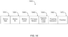
- Figure 16 shows the content of an RF Beacon data packet 1600.
- the data packet includes device type 1610, device id 1620, battery level 1630, firmware version 1640, transmit power level 1650, proximity indication 1660, and function 1670.
- Proximity indication comprises data corresponding to the presence/ranging technologies. For example, if a capacitive sensor detects a close proximity of a pet body, then the corresponding RF Beacon transmits data of the event, i.e. proximity indication, as a component of its repetitive communications.
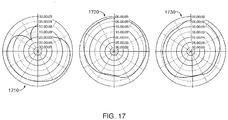
- Figure 17 shows example antennae patterns 1710, 1720, 1730 demonstrating differing signal strength levels depending on the approach angle of an RF Receiver relative to the respective RF Beacon.
- Figure 18 shows a transmitting RF Beacon X0.
- Figure 18 also shows RF Receivers X1-X11 positioned at various locations around the RF Beacon, i.e. positioned at differing approach angles.
- the RF Receivers detect the following signal strength (RSSI) levels.
- RSSI signal strength
- Figure 19 shows a dog with a collar 1910 that includes an RF Receiver.
- the RF Receiver of course repositions itself relative to the pet body over time as the pet and collar move around within an environment.
- Figure 19 also shows an RF Beacon 1920 periodically transmitting 1930 RF Beacon data.
- the various RF receiver collar positions ( X1-X3 , shown; X4-X6, not shown) register the following RSSI signal strength levels: X1 -67dB X4 -72dB X2 -70dB X5 -71dB X3 -65dB X6 -66dB
- a pet collar includes an RF Receiver.
- the receiver communicates with an RF Beacon incorporated into or affixed to a water bowl.
- the receiver logs close-proximity interactions between a pet wearing the collar and the beacon equipped water bowl.
- the RF Receiver knows that it is close to the water bowl; however, the RSSI distance estimate is not precise enough to establish with confidence that the pet is close enough to be drinking water versus just "nearby" the water bowl. Imprecision in the estimate may be due to one or more of an approach angle of the pet to the water bowl, position of the RF Receiver on the pet's neck, and the position of the RF Beacon on the water bowl. However, it is imperative that the log entry only occur upon very close proximity.
- a capacitive sensor is under one embodiment added to the circuitry of the RF Beacon. Upon very close approach of the pet body to the water bowl, the capacitive sensor begins to react. The reaction (sensor data) may be included in the data packet sent out by the RF Beacon. Once the RSSI threshold has been surpassed, AND the sensor data packet from the RF Beacon includes confirmation that a pet body is very nearby, the RF Receiver may confidently log the interaction.
- RF Receiver roams in proximity to two RF Beacon equipped bowls--a food bowl 2010 and a water bowl 2020.
- the food bowl 2010 features beacon 2080.
- Water bowl 2020 features beacon 2090.
- Each bowl also comprises a capacitive sensor 2030, 2040 for detecting near proximity of the pet wearing the RF Receiver.
- RF Receiver 2050 detects similar RSSI levels from the first RF Beacon 2060 and the second RF Beacon 2070. These RSSI levels surpass a threshold to indicate close proximity.
- the first capacitive sensor 2030 detects near proximity of the pet body while the second first capacitive sensor 2040 does not.
- the first RF Beacon transmission 2060 contains capacitive sensor data indicating proximity while the second RF Beacon transmission 2070 does not.
- the RF receiver is now aware of close proximity to the food bowl but not the water bowl.
- the RSSI value can vary significantly. Once a specified RSSI threshold value is surpassed, the RF Receiver knows that it is close to the trash can, however, not precisely enough to confidently apply a stimulus to the pet to discourage interaction between the pet and trash can.
- trash can 2110 is equipped with an RF Beacon 2120 which itself includes a capacitive sensor 2130.
- the RF Receiver 2170 detects similar RF readings at both positions.
- the capacitive sensor 2130 senses close proximity of the pet body.
- the RF Beacon transmissions 2160 include capacitive sensor data indicating close proximity. The combination of RSSI level and confirmed capacitive sensor event causes a pet collar to apply a stimulus encouraging the pet to exit an avoidance area surrounding the trash can.
- RF Receiver/Beacon components interact to provide a product coupon when an in store shopping consumer is directly in front of the product for a given period of time.
- the consumer uses a smartphone that supports RF Receiver capability (likely Bluetooth Low Energy) while the store shelf itself comprises an RF Beacon positioned near the product of interest.
- a consumer 2210 with smartphone 2220 approaches a product shelf to inspect an array of products.
- the shelf displays a first product 2230, a second product 2240, and a third product 2250.
- An RF Beacon 2260 may be placed directly behind, underneath or above the second product.
- the RF Receiver within the consumer's cell phone knows that it is close to an advertising beacon.
- the smartphone RF receiver may detect similar RSSI levels when in front of any of the three products.
- the smartphone RF receiver does not detect RSSI levels precisely enough to confidently know that the consumer is directly in front of the product that is coupon-enabled by an RF Beacon. It is imperative that the notification of the consumer occur only when the consumer is directly in front of the product for a specified period of time indicating the consumer has an interest in the product.
- the RF Beacon of an embodiment includes an ultrasonic ranging sensor 2270.
- the ultrasonic ranging sensor 2270 calculates the precise distance between the ultrasonic ranging sensor and consumer and includes this value within the data packet of the advertising RF Beacon. Once the RSSI threshold has been surpassed, and the data packet from the RF Beacon includes the further confirmation that the consumer has been stationary within close range for a sufficient time, an electronic coupon may be sent to the consumer's smartphone.
- RF Receiver/Beacon components interact to provide a driver vehicle position information relative to an interior wall of a garage.
- a driver moves a vehicle 2310 forward to position it within a garage space.
- the vehicle includes an RF Receiver 2320 located in a forward position while the interior wall of the garage includes an RF Beacon 2330.
- the vehicle moves from a first position 2340 to a second position 2350.
- a closing garage door will strike the back end of the vehicle.
- the front end of the car is sufficiently near to the interior wall (without risk of any collision between vehicle and wall) to provide clearance between the back end of the vehicle and a closed garage door.
- the RF Receiver detects similar RSSI levels at the first position and the second position.
- the vehicle RF receiver does not detect RSSI levels precisely enough to confidently establish the vehicle's position within the garage space. It is imperative that the vehicle pull up a fairly precise point to avoid contact with the wall and to allow the garage door to close behind the car.
- the RF Beacon may include an inductive sensor 2360 within its circuitry.
- the inductive sensor may detect nearby metal. Upon approach of the metallic vehicle toward the interior garage wall, the inductive sensor 2360 begin to reacts. The reaction data may be included in the data packets transmitted 2370 by the RF Beacon.
- the RF receiver may notify the driver that the vehicle is in a proper location.
- the RF Receiver may cooperate with sound emitting devices to provide the notification. Alternatively, the RF Receiver may cooperate with electronics within the vehicle to provide the notification via audible or visible alerts.
- a cook 2410 at a restaurant may work near a dangerously hot surface 2420.
- the cook may be outfitted with a wrist-mounted RF receiver 2430, while the hot surface 2420 may be outfitted with an RF beacon 2440.
- the cook may move from a first position 2450 to a second position 2460.
- the second position represents dangerous proximity to the hot surface.
- the RF Receiver detects similar RSSI levels at the first position and the second position. The RF receiver does not detect RSSI levels precisely enough to confidently establish the cook's location with respect to the hot surface.
- the RF Beacon may include an infrared ranging sensor 2470 within its circuitry. Upon the cook's approach toward the dangerous region, the infrared ranging sensor 2470 will measure the distance from the hot surface to the cook and place the result in the data packet sent out by the RF Beacon. In other words, the infrared ranging sensor data may be included in the data packets transmitted 2480 by the RF Beacon.
- the RF Receiver may notify the cook of danger.
- Figure 25 shows a system for enhancing RF Beacon proximity determination.
- the system comprises 2510 a communications device periodically transmitting a radio frequency signal, wherein the periodically transmitted signal includes data.
- the system comprises 2520 a receiver detecting the periodically transmitted signal, the detecting including measuring strength of the periodically transmitted signal, the detecting including using the signal strength to provide a first estimate of the receiver's distance from the communications device.
- the system comprises 2530 the communications device including at least one distance sensor for determining an additional distance indication, wherein the data includes the additional distance indication.
- the system comprises 2540 the receiver performing a function when the first estimate meets at least one criterion and when the additional distance indication indicates a first state.
- a system comprises a communications device periodically transmitting a radio frequency signal, wherein the periodically transmitted signal includes data.
- the system includes a receiver detecting the periodically transmitted signal, the detecting including measuring strength of the periodically transmitted signal, the detecting including using the signal strength to provide a first estimate of the receiver's distance from the communications device.
- the system includes the communications device including at least one distance sensor for detecting distance information for use in confirming the first estimate, where the data includes the distance information.
- the system includes the receiver performing a function when the first estimate meets at least one criterion and when the distance information indicates the first state.
- the data of an embodiment comprises an identification number of the communications device.
- the data of an embodiment comprises a type of the communications device..
- the data of an embodiment comprises battery level of the communications device.
- the data of an embodiment comprises version of firmware running on at least one processor of the communications device.
- the data of an embodiment comprises transmit power level of the communications device.
- the data of an embodiment comprises the function.
- the at least one criterion includes the first estimate being less than a first distance, under an embodiment.
- the at least one criterion includes the first estimate being greater than a first distance, under an embodiment.
- the at least one criterion includes the first estimate being equal to a first distance, under an embodiment.
- a mobile body of an embodiment comprises the receiver.
- the mobile body of an embodiment moves within an environment of the communications device.
- the detecting the periodically transmitted signal includes under an embodiment the mobile body moving within a detection range of the communications device.
- the mobile body of an embodiment comprises an animal, wherein the animal wears the receiver.
- the performing the function comprises applying under an embodiment at least one stimulus to the mobile body when the first estimate meets the at least one criterion and when the distance information indicates the first state.
- the performing the function comprises under an embodiment logging a time when the first estimate meets the at least one criterion and when the distance information indicates the first state.
- the logging the time includes under an embodiment associating the time with identification information of the communications device, wherein the data includes the identification information.
- the at least one distance sensor comprises a capacitive sensor, under an embodiment.
- the capacitive sensor of an embodiment detects the distance information including a presence of the mobile body that is conductive.
- the capacitive sensor of an embodiment detects the distance information including detecting a dielectric of the mobile body that is different from air.
- the at least one distance sensor of an embodiment comprises an inductive sensor.
- the inductive sensor of an embodiment detects the distance information including a presence of the mobile body, wherein the mobile body comprises a metallic object.
- the at least one distance sensor of an embodiment comprises a passive infrared (PIR) sensor.
- PIR passive infrared
- the PIR sensor of an embodiment detects the distance information including a presence of the mobile body within the PIR sensor's field of view.
- the at least one distance sensor of an embodiment comprises a first infrared ranging sensor.
- the first infrared ranging sensor of an embodiment detects the distance information including a presence of the mobile body within a second distance from the communications device.
- the at least one distance sensor of an embodiment comprises a second infrared ranging sensor.
- the second infrared ranging sensor of an embodiment detects the distance information including measuring the mobile body's distance from the communications device using two-way ranging.
- the at least one distance sensor of an embodiment comprises a laser.
- the laser of an embodiment detects the distance information including measuring the mobile body's distance from the communications device.
- the at least one distance sensor of an embodiment comprises an RF receiver.
- the RF receiver of an embodiment detects the distance information including a presence of the mobile body that is conductive.
- the communications device and the receiver of an embodiment wirelessly communicate through Bluetooth low energy communications protocols.
- the measured strength comprises a received signal strength indication, under an embodiment.
- the using the signal strength to provide the first estimate includes under an embodiment using a plurality of signal strength measurements to provide the first estimate.
- the using a plurality of signal strength measurements includes under an embodiment averaging the plurality of signal strength measurements to provide the first estimate.
- the communications device of an embodiment comprises a Bluetooth low energy beacon.
- Computer networks suitable for use with the embodiments described herein include local area networks (LAN), wide area networks (WAN), Internet, or other connection services and network variations such as the world wide web, the public internet, a private internet, a private computer network, a public network, a mobile network, a cellular network, a value-added network, and the like.
- Computing devices coupled or connected to the network may be any microprocessor controlled device that permits access to the network, including terminal devices, such as personal computers, workstations, servers, mini computers, main-frame computers, laptop computers, mobile computers, palm top computers, hand held computers, mobile phones, TV set-top boxes, or combinations thereof.
- the computer network may include one of more LANs, WANs, Internets, and computers.
- the computers may serve as servers, clients, or a combination thereof.
- the systems and methods of monitoring a subject in a premises can be a component of a single system, multiple systems, and/or geographically separate systems.
- the systems and methods of monitoring a subject in a premises can also be a subcomponent or subsystem of a single system, multiple systems, and/or geographically separate systems.
- the components of the systems and methods of monitoring a subject in a premises can be coupled to one or more other components (not shown) of a host system or a system coupled to the host system.
- One or more components of the systems and methods of monitoring a subject in a premises and/or a corresponding interface, system or application to which the systems and methods of monitoring a subject in a premises are coupled or connected includes and/or runs under and/or in association with a processing system.
- the processing system includes any collection of processor-based devices or computing devices operating together, or components of processing systems or devices, as is known in the art.
- the processing system can include one or more of a portable computer, portable communication device operating in a communication network, and/or a network server.
- the portable computer can be any of a number and/or combination of devices selected from among personal computers, personal digital assistants, portable computing devices, and portable communication devices, but is not so limited.
- the processing system can include components within a larger computer system.
- the processing system of an embodiment includes at least one processor and at least one memory device or subsystem.
- the processing system can also include or be coupled to at least one database.
- the term "processor” as generally used herein refers to any logic processing unit, such as one or more central processing units (CPUs), digital signal processors (DSPs), application-specific integrated circuits (ASIC), etc.
- the processor and memory can be monolithically integrated onto a single chip, distributed among a number of chips or components, and/or provided by some combination of algorithms.
- the methods described herein can be implemented in one or more of software algorithm(s), programs, firmware, hardware, components, circuitry, in any combination.
- Communication paths couple the components and include any medium for communicating or transferring files among the components.
- the communication paths include wireless connections, wired connections, and hybrid wireless/wired connections.
- the communication paths also include couplings or connections to networks including local area networks (LANs), metropolitan area networks (MANs), wide area networks (WANs), proprietary networks, interoffice or backend networks, and the Internet.
- LANs local area networks
- MANs metropolitan area networks
- WANs wide area networks
- proprietary networks interoffice or backend networks
- the Internet and the Internet.
- the communication paths include removable fixed mediums like floppy disks, hard disk drives, and CD-ROM disks, as well as flash RAM, Universal Serial Bus (USB) connections, RS-232 connections, telephone lines, buses, and electronic mail messages.
- USB Universal Serial Bus
- aspects of the systems and methods of monitoring a subject in a premises and corresponding systems and methods described herein may be implemented as functionality programmed into any of a variety of circuitry, including programmable logic devices (PLDs), such as field programmable gate arrays (FPGAs), programmable array logic (PAL) devices, electrically programmable logic and memory devices and standard cell-based devices, as well as application specific integrated circuits (ASICs).
- PLDs programmable logic devices
- FPGAs field programmable gate arrays
- PAL programmable array logic
- ASICs application specific integrated circuits
- microcontrollers with memory such as electronically erasable programmable read only memory (EEPROM)
- embedded microprocessors firmware, software, etc.
- aspects of the systems and methods of monitoring a subject in a premises and corresponding systems and methods may be embodied in microprocessors having software-based circuit emulation, discrete logic (sequential and combinatorial), custom devices, fuzzy (neural) logic, quantum devices, and hybrids of any of the above device types.
- the underlying device technologies may be provided in a variety of component types, e.g., metal-oxide semiconductor field-effect transistor (MOSFET) technologies like complementary metal-oxide semiconductor (CMOS), bipolar technologies like emitter-coupled logic (ECL), polymer technologies (e.g., silicon-conjugated polymer and metal-conjugated polymer-metal structures), mixed analog and digital, etc.
- MOSFET metal-oxide semiconductor field-effect transistor
- CMOS complementary metal-oxide semiconductor
- ECL emitter-coupled logic
- polymer technologies e.g., silicon-conjugated polymer and metal-conjugated polymer-metal structures
- mixed analog and digital
- any system, method, and/or other components disclosed herein may be described using computer aided design tools and expressed (or represented), as data and/or instructions embodied in various computer-readable media, in terms of their behavioral, register transfer, logic component, transistor, layout geometries, and/or other characteristics.
- Computer-readable media in which such formatted data and/or instructions may be embodied include, but are not limited to, non-volatile storage media in various forms (e.g., optical, magnetic or semiconductor storage media) and carrier waves that may be used to transfer such formatted data and/or instructions through wireless, optical, or wired signaling media or any combination thereof.
- Examples of transfers of such formatted data and/or instructions by carrier waves include, but are not limited to, transfers (uploads, downloads, e-mail, etc.) over the Internet and/or other computer networks via one or more data transfer protocols (e.g., HTTP, FTP, SMTP, etc.).
- data transfer protocols e.g., HTTP, FTP, SMTP, etc.
- a processing entity e.g., one or more processors
- processors within the computer system in conjunction with execution of one or more other computer programs.
Landscapes
- Engineering & Computer Science (AREA)
- Life Sciences & Earth Sciences (AREA)
- Computer Networks & Wireless Communication (AREA)
- Signal Processing (AREA)
- Environmental Sciences (AREA)
- Remote Sensing (AREA)
- Animal Husbandry (AREA)
- Physics & Mathematics (AREA)
- General Physics & Mathematics (AREA)
- Radar, Positioning & Navigation (AREA)
- General Health & Medical Sciences (AREA)
- Health & Medical Sciences (AREA)
- Biodiversity & Conservation Biology (AREA)
- Zoology (AREA)
- Animal Behavior & Ethology (AREA)
- Medical Informatics (AREA)
- Computing Systems (AREA)
- Physical Education & Sports Medicine (AREA)
- Birds (AREA)
- Telephone Function (AREA)
- Telephonic Communication Services (AREA)
Claims (15)
- Système pour estimer une distance d'un récepteur à un dispositif de communication, le système comprenant,
un dispositif de communication (1510, 2080, 2090, 2120, 2260, 2330) agencé pour transmettre périodiquement un signal radiofréquence (1530, 2060, 2070, 2170), dans lequel la transmission périodique d'un signal radiofréquence (1530, 2060, 2070, 2170), dans lequel le signal transmis périodiquement comprend des données ;
un récepteur (1540, 2050, 2170, 2220, 2320) agencé pour détecter le signal transmis périodiquement, pour mesurer l'intensité du signal transmis périodiquement, et pour utiliser l'intensité de signal pour fournir une première estimation de la distance du récepteur par rapport au dispositif de communication ;
caractérisé en ce que le système comprend en outre :le dispositif de communication comprenant au moins un capteur de distance (1520, 2030, 2040, 2130, 2270, 2360) pour détecter des informations de distance à utiliser pour confirmer la première estimation, dans lequel les données comprennent les informations de distance, dans lequel les informations de distance concernent la distance entre l'appareil de communication et le récepteur ;le récepteur étant agencé pour utiliser les informations de distance afin de confirmer la première estimation, la confirmation de la première estimation comprenant les informations de distance indiquant un premier état ;le récepteur étant agencé pour exécuter une fonction lorsque la première estimation satisfait au moins un critère et lorsque l'information de distance indique le premier état. - Système selon la revendication 1, dans lequel les données comprennent au moins un parmi :un numéro d'identification du dispositif de communication ;un type du dispositif de communication ;un niveau de batterie du dispositif de communication ;une version de micrologiciel fonctionnant sur au moins un processeur du dispositif de communication ;un niveau de puissance de transmission du dispositif de communication ; etla fonction.
- Système selon la revendication 1 ou la revendication 2, dans lequel le au moins un critère comprend une parmi :la première estimation étant inférieure à une première distance ;la première estimation étant supérieure à une première distance ; oula première estimation étant égale à une première distance.
- Système selon la revendication 3, dans lequel le récepteur se déplace dans un environnement du dispositif de communication.
- Système selon la revendication 4, la détection du signal transmis périodiquement comprenant le récepteur se déplaçant dans une plage de détection du dispositif de communication.
- Système selon la revendication 4, dans lequel le récepteur est configuré pour être fixé à un animal domestique.
- Système selon la revendication 6, dans lequel l'exécution de la fonction comprend l'application d'au moins un stimulus à l'animal domestique lorsque la première estimation satisfait le au moins un critère et lorsque les informations de distance indiquent le premier état.
- Système selon l'une quelconque des revendications 1 à 7, dans lequel l'exécution de la fonction comprend l'enregistrement d'un instant où la première estimation satisfait le au moins un critère et lorsque les informations de distance indiquent le premier état.
- Système selon la revendication 8, dans lequel l'enregistrement de l'instant comprend l'association de l'instant avec des informations d'identification du dispositif de communication, dans lequel les données comprennent les informations d'identification.
- Système selon l'une quelconque des revendications 1 à 9, dans lequel le au moins un capteur de distance comprend au moins un parmi : un capteur capacitif ; un capteur inductif ; un capteur infrarouge passif (PIR) ; un premier capteur de télémétrie infrarouge ; un second capteur de télémétrie infrarouge ; un laser ; et un récepteur RF.
- Système selon l'une quelconque des revendications 1 à 10, dans lequel le dispositif de communication et le récepteur sont agencés pour communiquer sans fil via des protocoles de communication Bluetooth à faible énergie.
- Système selon l'une quelconque des revendications 1 à 11, l'intensité mesurée comprenant une indication d'intensité de signal reçu.
- Système selon l'une quelconque des revendications 1 à 12, dans lequel le récepteur est agencé pour utiliser une pluralité de mesures d'intensité de signal reçu pour fournir la première estimation.
- Système selon la revendication 13, dans lequel le récepteur est agencé pour calculer la moyenne de la pluralité de mesures d'intensité de signal reçu pour fournir la première estimation.
- Système selon l'une quelconque des revendications 1 à 14, dans lequel le dispositif de communication comprend une balise Bluetooth à faible énergie.
Applications Claiming Priority (1)
| Application Number | Priority Date | Filing Date | Title |
|---|---|---|---|
| US15/078,499 US10231440B2 (en) | 2015-06-16 | 2016-03-23 | RF beacon proximity determination enhancement |
Publications (2)
| Publication Number | Publication Date |
|---|---|
| EP3225105A1 EP3225105A1 (fr) | 2017-10-04 |
| EP3225105B1 true EP3225105B1 (fr) | 2021-01-13 |
Family
ID=58401471
Family Applications (1)
| Application Number | Title | Priority Date | Filing Date |
|---|---|---|---|
| EP17162289.7A Active EP3225105B1 (fr) | 2016-03-23 | 2017-03-22 | Amélioration de la détermination de proximité de balise rf |
Country Status (3)
| Country | Link |
|---|---|
| EP (1) | EP3225105B1 (fr) |
| CN (1) | CN107333223B (fr) |
| ES (1) | ES2854926T3 (fr) |
Families Citing this family (5)
| Publication number | Priority date | Publication date | Assignee | Title |
|---|---|---|---|---|
| US20240371249A1 (en) * | 2016-01-31 | 2024-11-07 | Robert Louis Piccioni | Public Safety Smart Belt |
| CN108371108A (zh) * | 2018-02-07 | 2018-08-07 | 深圳市沃特沃德股份有限公司 | 自动投食方法和装置 |
| SE543574C2 (en) * | 2018-11-26 | 2021-03-30 | Crunchfish Proximity Ab C/O Crunchfish Ab | Triggering a proximity-based digital action with a mobile device and a base device |
| AU2020217761B2 (en) * | 2019-02-04 | 2025-11-27 | Radio Systems Corporation | Systems and methods for providing a sound masking environment |
| CN111757303A (zh) * | 2019-03-26 | 2020-10-09 | 华为技术有限公司 | 一种蓝牙发射功率的控制方法以及终端设备 |
Family Cites Families (8)
| Publication number | Priority date | Publication date | Assignee | Title |
|---|---|---|---|---|
| US20120000431A1 (en) * | 2010-07-05 | 2012-01-05 | Kamran Khoshkish | Electronic Pet Containment System |
| EP2679034B1 (fr) * | 2011-02-25 | 2018-08-01 | BlackBerry Limited | Détermination de la proximité de dispositifs à l'intérieur d'une portée de communication |
| US20140253389A1 (en) * | 2013-03-08 | 2014-09-11 | Qualcomm Incorporated | Ranging using wi-fi and ultrasound measurements communication |
| US9538725B2 (en) * | 2013-03-08 | 2017-01-10 | Eb Partners | Mobile telephone dog training tool and method |
| WO2015015047A1 (fr) * | 2013-08-02 | 2015-02-05 | Nokia Corporation | Estimation de distance |
| US9894633B2 (en) * | 2013-12-06 | 2018-02-13 | Google Llc | Reminders based on device proximity using bluetooth LE |
| CN104756892A (zh) * | 2015-04-10 | 2015-07-08 | 苏州新区枫桥净化设备厂 | 一种距离监视宠物笼 |
| CN105043164A (zh) * | 2015-06-18 | 2015-11-11 | 深圳市润安科技发展有限公司 | 一种防脱离系统及防脱离方法 |
-
2017
- 2017-03-22 CN CN201710175497.4A patent/CN107333223B/zh active Active
- 2017-03-22 ES ES17162289T patent/ES2854926T3/es active Active
- 2017-03-22 EP EP17162289.7A patent/EP3225105B1/fr active Active
Non-Patent Citations (1)
| Title |
|---|
| None * |
Also Published As
| Publication number | Publication date |
|---|---|
| EP3225105A1 (fr) | 2017-10-04 |
| CN107333223B (zh) | 2021-06-08 |
| ES2854926T3 (es) | 2021-09-23 |
| CN107333223A (zh) | 2017-11-07 |
Similar Documents
| Publication | Publication Date | Title |
|---|---|---|
| US12089565B2 (en) | Systems and methods for monitoring a subject in a premise | |
| US10645908B2 (en) | Systems and methods for providing a sound masking environment | |
| EP3311370B1 (fr) | Systèmes et procédés pour surveiller un sujet dans un local | |
| US12616173B2 (en) | Apparatus and method for delivering an auditory stimulus | |
| EP3225105A1 (fr) | Amélioration de la détermination de proximité de balise rf | |
| US11893872B2 (en) | System and methods for wireless hand hygiene monitoring | |
| US10297140B2 (en) | Emergency response and tracking using lighting networks | |
| US20160366854A1 (en) | Systems and methods for monitoring a subject in a premises | |
| US20150289112A1 (en) | Identification of a subject in a facility | |
| AU2020217761B2 (en) | Systems and methods for providing a sound masking environment | |
| Schwiegelshohn et al. | Enabling indoor object localization through Bluetooth beacons on the RADIO robot platform | |
| KR20160045423A (ko) | 반려동물 목걸이를 활용한 분실방지 및 건강관리 시스템 | |
| CA2945148C (fr) | Systèmes et procédés pour surveiller un sujet dans un local | |
| NL2005784C2 (en) | Locating and tracking system. | |
| KR101140642B1 (ko) | 지그비 통신방식의 관리 대상자의 위치 및 상태 관리 시스템과 그 방법 | |
| CA3160791A1 (fr) | Appareil et procede destines a fournir un stimulus auditif | |
| US20200029175A1 (en) | Information processing system | |
| KR20230076393A (ko) | 해킹 방지 및 개인정보 보안 강화를 위한 스마트 무선 마을 방송 시스템 |
Legal Events
| Date | Code | Title | Description |
|---|---|---|---|
| PUAI | Public reference made under article 153(3) epc to a published international application that has entered the european phase |
Free format text: ORIGINAL CODE: 0009012 |
|
| STAA | Information on the status of an ep patent application or granted ep patent |
Free format text: STATUS: THE APPLICATION HAS BEEN PUBLISHED |
|
| AK | Designated contracting states |
Kind code of ref document: A1 Designated state(s): AL AT BE BG CH CY CZ DE DK EE ES FI FR GB GR HR HU IE IS IT LI LT LU LV MC MK MT NL NO PL PT RO RS SE SI SK SM TR |
|
| AX | Request for extension of the european patent |
Extension state: BA ME |
|
| STAA | Information on the status of an ep patent application or granted ep patent |
Free format text: STATUS: REQUEST FOR EXAMINATION WAS MADE |
|
| 17P | Request for examination filed |
Effective date: 20180403 |
|
| RBV | Designated contracting states (corrected) |
Designated state(s): AL AT BE BG CH CY CZ DE DK EE ES FI FR GB GR HR HU IE IS IT LI LT LU LV MC MK MT NL NO PL PT RO RS SE SI SK SM TR |
|
| STAA | Information on the status of an ep patent application or granted ep patent |
Free format text: STATUS: EXAMINATION IS IN PROGRESS |
|
| 17Q | First examination report despatched |
Effective date: 20200206 |
|
| GRAP | Despatch of communication of intention to grant a patent |
Free format text: ORIGINAL CODE: EPIDOSNIGR1 |
|
| STAA | Information on the status of an ep patent application or granted ep patent |
Free format text: STATUS: GRANT OF PATENT IS INTENDED |
|
| INTG | Intention to grant announced |
Effective date: 20200618 |
|
| GRAJ | Information related to disapproval of communication of intention to grant by the applicant or resumption of examination proceedings by the epo deleted |
Free format text: ORIGINAL CODE: EPIDOSDIGR1 |
|
| STAA | Information on the status of an ep patent application or granted ep patent |
Free format text: STATUS: EXAMINATION IS IN PROGRESS |
|
| INTC | Intention to grant announced (deleted) | ||
| RAP1 | Party data changed (applicant data changed or rights of an application transferred) |
Owner name: RADIO SYSTEMS CORPORATION |
|
| RIN1 | Information on inventor provided before grant (corrected) |
Inventor name: MAININI, CHRISTOPHER Inventor name: SELTZER, RICHARD ALAN |
|
| GRAR | Information related to intention to grant a patent recorded |
Free format text: ORIGINAL CODE: EPIDOSNIGR71 |
|
| GRAS | Grant fee paid |
Free format text: ORIGINAL CODE: EPIDOSNIGR3 |
|
| STAA | Information on the status of an ep patent application or granted ep patent |
Free format text: STATUS: GRANT OF PATENT IS INTENDED |
|
| GRAA | (expected) grant |
Free format text: ORIGINAL CODE: 0009210 |
|
| STAA | Information on the status of an ep patent application or granted ep patent |
Free format text: STATUS: THE PATENT HAS BEEN GRANTED |
|
| INTG | Intention to grant announced |
Effective date: 20201203 |
|
| AK | Designated contracting states |
Kind code of ref document: B1 Designated state(s): AL AT BE BG CH CY CZ DE DK EE ES FI FR GB GR HR HU IE IS IT LI LT LU LV MC MK MT NL NO PL PT RO RS SE SI SK SM TR |
|
| REG | Reference to a national code |
Ref country code: GB Ref legal event code: FG4D |
|
| REG | Reference to a national code |
Ref country code: CH Ref legal event code: EP |
|
| REG | Reference to a national code |
Ref country code: IE Ref legal event code: FG4D |
|
| REG | Reference to a national code |
Ref country code: DE Ref legal event code: R096 Ref document number: 602017031263 Country of ref document: DE |
|
| REG | Reference to a national code |
Ref country code: AT Ref legal event code: REF Ref document number: 1353853 Country of ref document: AT Kind code of ref document: T Effective date: 20210215 |
|
| REG | Reference to a national code |
Ref country code: AT Ref legal event code: MK05 Ref document number: 1353853 Country of ref document: AT Kind code of ref document: T Effective date: 20210113 |
|
| REG | Reference to a national code |
Ref country code: NL Ref legal event code: MP Effective date: 20210113 |
|
| REG | Reference to a national code |
Ref country code: LT Ref legal event code: MG9D |
|
| PG25 | Lapsed in a contracting state [announced via postgrant information from national office to epo] |
Ref country code: NO Free format text: LAPSE BECAUSE OF FAILURE TO SUBMIT A TRANSLATION OF THE DESCRIPTION OR TO PAY THE FEE WITHIN THE PRESCRIBED TIME-LIMIT Effective date: 20210413 Ref country code: PT Free format text: LAPSE BECAUSE OF FAILURE TO SUBMIT A TRANSLATION OF THE DESCRIPTION OR TO PAY THE FEE WITHIN THE PRESCRIBED TIME-LIMIT Effective date: 20210513 Ref country code: HR Free format text: LAPSE BECAUSE OF FAILURE TO SUBMIT A TRANSLATION OF THE DESCRIPTION OR TO PAY THE FEE WITHIN THE PRESCRIBED TIME-LIMIT Effective date: 20210113 Ref country code: GR Free format text: LAPSE BECAUSE OF FAILURE TO SUBMIT A TRANSLATION OF THE DESCRIPTION OR TO PAY THE FEE WITHIN THE PRESCRIBED TIME-LIMIT Effective date: 20210414 Ref country code: FI Free format text: LAPSE BECAUSE OF FAILURE TO SUBMIT A TRANSLATION OF THE DESCRIPTION OR TO PAY THE FEE WITHIN THE PRESCRIBED TIME-LIMIT Effective date: 20210113 Ref country code: BG Free format text: LAPSE BECAUSE OF FAILURE TO SUBMIT A TRANSLATION OF THE DESCRIPTION OR TO PAY THE FEE WITHIN THE PRESCRIBED TIME-LIMIT Effective date: 20210413 Ref country code: LT Free format text: LAPSE BECAUSE OF FAILURE TO SUBMIT A TRANSLATION OF THE DESCRIPTION OR TO PAY THE FEE WITHIN THE PRESCRIBED TIME-LIMIT Effective date: 20210113 |
|
| PG25 | Lapsed in a contracting state [announced via postgrant information from national office to epo] |
Ref country code: SE Free format text: LAPSE BECAUSE OF FAILURE TO SUBMIT A TRANSLATION OF THE DESCRIPTION OR TO PAY THE FEE WITHIN THE PRESCRIBED TIME-LIMIT Effective date: 20210113 Ref country code: AT Free format text: LAPSE BECAUSE OF FAILURE TO SUBMIT A TRANSLATION OF THE DESCRIPTION OR TO PAY THE FEE WITHIN THE PRESCRIBED TIME-LIMIT Effective date: 20210113 Ref country code: RS Free format text: LAPSE BECAUSE OF FAILURE TO SUBMIT A TRANSLATION OF THE DESCRIPTION OR TO PAY THE FEE WITHIN THE PRESCRIBED TIME-LIMIT Effective date: 20210113 Ref country code: LV Free format text: LAPSE BECAUSE OF FAILURE TO SUBMIT A TRANSLATION OF THE DESCRIPTION OR TO PAY THE FEE WITHIN THE PRESCRIBED TIME-LIMIT Effective date: 20210113 Ref country code: PL Free format text: LAPSE BECAUSE OF FAILURE TO SUBMIT A TRANSLATION OF THE DESCRIPTION OR TO PAY THE FEE WITHIN THE PRESCRIBED TIME-LIMIT Effective date: 20210113 |
|
| REG | Reference to a national code |
Ref country code: ES Ref legal event code: FG2A Ref document number: 2854926 Country of ref document: ES Kind code of ref document: T3 Effective date: 20210923 |
|
| PG25 | Lapsed in a contracting state [announced via postgrant information from national office to epo] |
Ref country code: IS Free format text: LAPSE BECAUSE OF FAILURE TO SUBMIT A TRANSLATION OF THE DESCRIPTION OR TO PAY THE FEE WITHIN THE PRESCRIBED TIME-LIMIT Effective date: 20210513 |
|
| REG | Reference to a national code |
Ref country code: DE Ref legal event code: R097 Ref document number: 602017031263 Country of ref document: DE |
|
| PG25 | Lapsed in a contracting state [announced via postgrant information from national office to epo] |
Ref country code: SM Free format text: LAPSE BECAUSE OF FAILURE TO SUBMIT A TRANSLATION OF THE DESCRIPTION OR TO PAY THE FEE WITHIN THE PRESCRIBED TIME-LIMIT Effective date: 20210113 Ref country code: MC Free format text: LAPSE BECAUSE OF FAILURE TO SUBMIT A TRANSLATION OF THE DESCRIPTION OR TO PAY THE FEE WITHIN THE PRESCRIBED TIME-LIMIT Effective date: 20210113 Ref country code: EE Free format text: LAPSE BECAUSE OF FAILURE TO SUBMIT A TRANSLATION OF THE DESCRIPTION OR TO PAY THE FEE WITHIN THE PRESCRIBED TIME-LIMIT Effective date: 20210113 Ref country code: CZ Free format text: LAPSE BECAUSE OF FAILURE TO SUBMIT A TRANSLATION OF THE DESCRIPTION OR TO PAY THE FEE WITHIN THE PRESCRIBED TIME-LIMIT Effective date: 20210113 |
|
| REG | Reference to a national code |
Ref country code: CH Ref legal event code: PL |
|
| PLBE | No opposition filed within time limit |
Free format text: ORIGINAL CODE: 0009261 |
|
| STAA | Information on the status of an ep patent application or granted ep patent |
Free format text: STATUS: NO OPPOSITION FILED WITHIN TIME LIMIT |
|
| PG25 | Lapsed in a contracting state [announced via postgrant information from national office to epo] |
Ref country code: SK Free format text: LAPSE BECAUSE OF FAILURE TO SUBMIT A TRANSLATION OF THE DESCRIPTION OR TO PAY THE FEE WITHIN THE PRESCRIBED TIME-LIMIT Effective date: 20210113 Ref country code: RO Free format text: LAPSE BECAUSE OF FAILURE TO SUBMIT A TRANSLATION OF THE DESCRIPTION OR TO PAY THE FEE WITHIN THE PRESCRIBED TIME-LIMIT Effective date: 20210113 Ref country code: DK Free format text: LAPSE BECAUSE OF FAILURE TO SUBMIT A TRANSLATION OF THE DESCRIPTION OR TO PAY THE FEE WITHIN THE PRESCRIBED TIME-LIMIT Effective date: 20210113 |
|
| 26N | No opposition filed |
Effective date: 20211014 |
|
| PG25 | Lapsed in a contracting state [announced via postgrant information from national office to epo] |
Ref country code: CH Free format text: LAPSE BECAUSE OF NON-PAYMENT OF DUE FEES Effective date: 20210331 Ref country code: AL Free format text: LAPSE BECAUSE OF FAILURE TO SUBMIT A TRANSLATION OF THE DESCRIPTION OR TO PAY THE FEE WITHIN THE PRESCRIBED TIME-LIMIT Effective date: 20210113 Ref country code: LI Free format text: LAPSE BECAUSE OF NON-PAYMENT OF DUE FEES Effective date: 20210331 Ref country code: LU Free format text: LAPSE BECAUSE OF NON-PAYMENT OF DUE FEES Effective date: 20210322 |
|
| PG25 | Lapsed in a contracting state [announced via postgrant information from national office to epo] |
Ref country code: SI Free format text: LAPSE BECAUSE OF FAILURE TO SUBMIT A TRANSLATION OF THE DESCRIPTION OR TO PAY THE FEE WITHIN THE PRESCRIBED TIME-LIMIT Effective date: 20210113 |
|
| PG25 | Lapsed in a contracting state [announced via postgrant information from national office to epo] |
Ref country code: IS Free format text: LAPSE BECAUSE OF FAILURE TO SUBMIT A TRANSLATION OF THE DESCRIPTION OR TO PAY THE FEE WITHIN THE PRESCRIBED TIME-LIMIT Effective date: 20210513 |
|
| PG25 | Lapsed in a contracting state [announced via postgrant information from national office to epo] |
Ref country code: HU Free format text: LAPSE BECAUSE OF FAILURE TO SUBMIT A TRANSLATION OF THE DESCRIPTION OR TO PAY THE FEE WITHIN THE PRESCRIBED TIME-LIMIT; INVALID AB INITIO Effective date: 20170322 |
|
| P01 | Opt-out of the competence of the unified patent court (upc) registered |
Effective date: 20230506 |
|
| PG25 | Lapsed in a contracting state [announced via postgrant information from national office to epo] |
Ref country code: NL Free format text: LAPSE BECAUSE OF NON-PAYMENT OF DUE FEES Effective date: 20210113 Ref country code: CY Free format text: LAPSE BECAUSE OF FAILURE TO SUBMIT A TRANSLATION OF THE DESCRIPTION OR TO PAY THE FEE WITHIN THE PRESCRIBED TIME-LIMIT Effective date: 20210113 |
|
| PG25 | Lapsed in a contracting state [announced via postgrant information from national office to epo] |
Ref country code: MK Free format text: LAPSE BECAUSE OF FAILURE TO SUBMIT A TRANSLATION OF THE DESCRIPTION OR TO PAY THE FEE WITHIN THE PRESCRIBED TIME-LIMIT Effective date: 20210113 |
|
| PG25 | Lapsed in a contracting state [announced via postgrant information from national office to epo] |
Ref country code: MT Free format text: LAPSE BECAUSE OF FAILURE TO SUBMIT A TRANSLATION OF THE DESCRIPTION OR TO PAY THE FEE WITHIN THE PRESCRIBED TIME-LIMIT Effective date: 20210113 |
|
| PGFP | Annual fee paid to national office [announced via postgrant information from national office to epo] |
Ref country code: ES Payment date: 20250414 Year of fee payment: 9 |
|
| PG25 | Lapsed in a contracting state [announced via postgrant information from national office to epo] |
Ref country code: TR Free format text: LAPSE BECAUSE OF FAILURE TO SUBMIT A TRANSLATION OF THE DESCRIPTION OR TO PAY THE FEE WITHIN THE PRESCRIBED TIME-LIMIT Effective date: 20210113 |
|
| PGFP | Annual fee paid to national office [announced via postgrant information from national office to epo] |
Ref country code: FR Payment date: 20251231 Year of fee payment: 10 |
|
| PGFP | Annual fee paid to national office [announced via postgrant information from national office to epo] |
Ref country code: GB Payment date: 20260106 Year of fee payment: 10 |
|
| PGFP | Annual fee paid to national office [announced via postgrant information from national office to epo] |
Ref country code: DE Payment date: 20260102 Year of fee payment: 10 Ref country code: IE Payment date: 20260102 Year of fee payment: 10 |
|
| PGFP | Annual fee paid to national office [announced via postgrant information from national office to epo] |
Ref country code: IT Payment date: 20260220 Year of fee payment: 10 Ref country code: BE Payment date: 20260105 Year of fee payment: 10 |