EP3225423A1 - Ensemble d'essieu - Google Patents
Ensemble d'essieu Download PDFInfo
- Publication number
- EP3225423A1 EP3225423A1 EP16162665.0A EP16162665A EP3225423A1 EP 3225423 A1 EP3225423 A1 EP 3225423A1 EP 16162665 A EP16162665 A EP 16162665A EP 3225423 A1 EP3225423 A1 EP 3225423A1
- Authority
- EP
- European Patent Office
- Prior art keywords
- axle
- groove
- mating surface
- flange
- differential
- Prior art date
- Legal status (The legal status is an assumption and is not a legal conclusion. Google has not performed a legal analysis and makes no representation as to the accuracy of the status listed.)
- Withdrawn
Links
- 230000013011 mating Effects 0.000 claims abstract description 67
- 238000007789 sealing Methods 0.000 claims abstract description 15
- 239000000565 sealant Substances 0.000 claims description 16
- 239000000463 material Substances 0.000 claims description 6
- 229920001296 polysiloxane Polymers 0.000 claims description 3
- 229920000642 polymer Polymers 0.000 claims description 2
- 238000000034 method Methods 0.000 claims 3
- 239000012530 fluid Substances 0.000 description 8
- 238000001816 cooling Methods 0.000 description 2
- 239000004590 silicone sealant Substances 0.000 description 2
- 229910001018 Cast iron Inorganic materials 0.000 description 1
- 230000015572 biosynthetic process Effects 0.000 description 1
- 238000005266 casting Methods 0.000 description 1
- 230000009977 dual effect Effects 0.000 description 1
- 230000001050 lubricating effect Effects 0.000 description 1
- 238000005461 lubrication Methods 0.000 description 1
- 238000003754 machining Methods 0.000 description 1
- 239000002184 metal Substances 0.000 description 1
- 229910052751 metal Inorganic materials 0.000 description 1
- 230000000717 retained effect Effects 0.000 description 1
- 239000012812 sealant material Substances 0.000 description 1
Images


Classifications
-
- B—PERFORMING OPERATIONS; TRANSPORTING
- B60—VEHICLES IN GENERAL
- B60B—VEHICLE WHEELS; CASTORS; AXLES FOR WHEELS OR CASTORS; INCREASING WHEEL ADHESION
- B60B35/00—Axle units; Parts thereof ; Arrangements for lubrication of axles
- B60B35/12—Torque-transmitting axles
- B60B35/16—Axle housings
- B60B35/163—Axle housings characterised by specific shape of the housing, e.g. adaptations to give space for other vehicle elements like chassis or exhaust system
-
- B—PERFORMING OPERATIONS; TRANSPORTING
- B60—VEHICLES IN GENERAL
- B60B—VEHICLE WHEELS; CASTORS; AXLES FOR WHEELS OR CASTORS; INCREASING WHEEL ADHESION
- B60B35/00—Axle units; Parts thereof ; Arrangements for lubrication of axles
- B60B35/12—Torque-transmitting axles
- B60B35/14—Torque-transmitting axles composite or split, e.g. half- axles; Couplings between axle parts or sections
-
- B—PERFORMING OPERATIONS; TRANSPORTING
- B60—VEHICLES IN GENERAL
- B60B—VEHICLE WHEELS; CASTORS; AXLES FOR WHEELS OR CASTORS; INCREASING WHEEL ADHESION
- B60B35/00—Axle units; Parts thereof ; Arrangements for lubrication of axles
- B60B35/12—Torque-transmitting axles
- B60B35/16—Axle housings
-
- F—MECHANICAL ENGINEERING; LIGHTING; HEATING; WEAPONS; BLASTING
- F16—ENGINEERING ELEMENTS AND UNITS; GENERAL MEASURES FOR PRODUCING AND MAINTAINING EFFECTIVE FUNCTIONING OF MACHINES OR INSTALLATIONS; THERMAL INSULATION IN GENERAL
- F16H—GEARING
- F16H48/00—Differential gearings
- F16H48/06—Differential gearings with gears having orbital motion
- F16H48/08—Differential gearings with gears having orbital motion comprising bevel gears
-
- B—PERFORMING OPERATIONS; TRANSPORTING
- B60—VEHICLES IN GENERAL
- B60B—VEHICLE WHEELS; CASTORS; AXLES FOR WHEELS OR CASTORS; INCREASING WHEEL ADHESION
- B60B2310/00—Manufacturing methods
- B60B2310/20—Shaping
-
- B—PERFORMING OPERATIONS; TRANSPORTING
- B60—VEHICLES IN GENERAL
- B60B—VEHICLE WHEELS; CASTORS; AXLES FOR WHEELS OR CASTORS; INCREASING WHEEL ADHESION
- B60B2320/00—Manufacturing or maintenance operations
- B60B2320/10—Assembling; disassembling
-
- B—PERFORMING OPERATIONS; TRANSPORTING
- B60—VEHICLES IN GENERAL
- B60B—VEHICLE WHEELS; CASTORS; AXLES FOR WHEELS OR CASTORS; INCREASING WHEEL ADHESION
- B60B2900/00—Purpose of invention
- B60B2900/50—Improvement of
- B60B2900/511—Sealing
-
- B—PERFORMING OPERATIONS; TRANSPORTING
- B60—VEHICLES IN GENERAL
- B60B—VEHICLE WHEELS; CASTORS; AXLES FOR WHEELS OR CASTORS; INCREASING WHEEL ADHESION
- B60B35/00—Axle units; Parts thereof ; Arrangements for lubrication of axles
- B60B35/12—Torque-transmitting axles
- B60B35/121—Power-transmission from drive shaft to hub
-
- B—PERFORMING OPERATIONS; TRANSPORTING
- B60—VEHICLES IN GENERAL
- B60K—ARRANGEMENT OR MOUNTING OF PROPULSION UNITS OR OF TRANSMISSIONS IN VEHICLES; ARRANGEMENT OR MOUNTING OF PLURAL DIVERSE PRIME-MOVERS IN VEHICLES; AUXILIARY DRIVES FOR VEHICLES; INSTRUMENTATION OR DASHBOARDS FOR VEHICLES; ARRANGEMENTS IN CONNECTION WITH COOLING, AIR INTAKE, GAS EXHAUST OR FUEL SUPPLY OF PROPULSION UNITS IN VEHICLES
- B60K17/00—Arrangement or mounting of transmissions in vehicles
- B60K17/04—Arrangement or mounting of transmissions in vehicles characterised by arrangement, location or kind of gearing
- B60K17/16—Arrangement or mounting of transmissions in vehicles characterised by arrangement, location or kind of gearing of differential gearing
- B60K17/165—Arrangement or mounting of transmissions in vehicles characterised by arrangement, location or kind of gearing of differential gearing provided between independent half axles
-
- F—MECHANICAL ENGINEERING; LIGHTING; HEATING; WEAPONS; BLASTING
- F16—ENGINEERING ELEMENTS AND UNITS; GENERAL MEASURES FOR PRODUCING AND MAINTAINING EFFECTIVE FUNCTIONING OF MACHINES OR INSTALLATIONS; THERMAL INSULATION IN GENERAL
- F16H—GEARING
- F16H48/00—Differential gearings
- F16H48/38—Constructional details
- F16H2048/382—Methods for manufacturing differential gearings
-
- F—MECHANICAL ENGINEERING; LIGHTING; HEATING; WEAPONS; BLASTING
- F16—ENGINEERING ELEMENTS AND UNITS; GENERAL MEASURES FOR PRODUCING AND MAINTAINING EFFECTIVE FUNCTIONING OF MACHINES OR INSTALLATIONS; THERMAL INSULATION IN GENERAL
- F16H—GEARING
- F16H48/00—Differential gearings
- F16H48/38—Constructional details
- F16H48/40—Constructional details characterised by features of the rotating cases
-
- F—MECHANICAL ENGINEERING; LIGHTING; HEATING; WEAPONS; BLASTING
- F16—ENGINEERING ELEMENTS AND UNITS; GENERAL MEASURES FOR PRODUCING AND MAINTAINING EFFECTIVE FUNCTIONING OF MACHINES OR INSTALLATIONS; THERMAL INSULATION IN GENERAL
- F16H—GEARING
- F16H57/00—General details of gearing
- F16H57/02—Gearboxes; Mounting gearing therein
- F16H57/031—Gearboxes; Mounting gearing therein characterised by covers or lids for gearboxes
-
- F—MECHANICAL ENGINEERING; LIGHTING; HEATING; WEAPONS; BLASTING
- F16—ENGINEERING ELEMENTS AND UNITS; GENERAL MEASURES FOR PRODUCING AND MAINTAINING EFFECTIVE FUNCTIONING OF MACHINES OR INSTALLATIONS; THERMAL INSULATION IN GENERAL
- F16H—GEARING
- F16H57/00—General details of gearing
- F16H57/02—Gearboxes; Mounting gearing therein
- F16H57/037—Gearboxes for accommodating differential gearings
Definitions
- the present invention relates to an axle assembly, in particular an axle assembly for a heavy vehicle such as a lorry or truck.
- Road vehicles which include driven rear axles.
- the rear axles includes a crown wheel and pinion and differential.
- the pinion is driven via a drive shaft or the like connected to a prime mover such as an engine.
- the pinion and drive shaft rotate about a longitudinal axis of the vehicle.
- the pinion together with the crown wheel enables the crown wheel to rotate about an axis which is laterally orientated relative to the vehicle.
- the crown wheel drives a differential mechanism which drive a right and left hand drive shaft (known as half shafts).
- the right hand drive shaft drives a right hand wheel rotatably mounted to the axle and the left hand drive shaft drives a left hand wheel rotatably mounted to the axle. In this way the vehicle can be driven over the ground.
- the crown wheel, pinion and differential assembly require lubrication and cooling and a fluid, typically an oil, will perform this dual function.
- the crown wheel, pinion and differential assembly are mounted on a differential carrier assembly that is fixed to the axle housing by bolts.
- the axle housing and the differential carrier assembly experience vertical, longitudinal and torsional forces, which cause deformation of the axle housing and the differential carrier assembly. This causes leakage of the fluid from the resulting gaps between the differential carrier assembly and the axle housing.
- an axle assembly including an axle housing having a central portion for receiving a differential, a first axle tube extending from the central portion, and a second axle tube extending from the central portion, the central portion having an opening defined by an axle flange, the axle flange having a first mating surface.
- the axle assembly further includes a differential carrier assembly having a differential mounted on a carrier, the carrier having a carrier flange which has a second mating surface. The first mating surface is sealed to the second sealing surface by sealing means. At least one of the first and/or second mating surfaces includes a groove.
- a groove in at least one of the mating surfaces reduces the leakage of fluid from the axle assembly.
- the groove enables the inclusion of a thicker sealing means, which fills a larger gap than standard sealing means. Because the gap to be filled is larger, then the local thickness of the sealing means is thicker and this locally thicker sealing means can better withstand deflections, and thereby better prevent leakage of fluid.
- the central portion may be formed by casting.
- the opening may be generally circular.
- the first mating surface may be generally flat.
- the differential carrier assembly may include a crown wheel in driving engagement with a pinion.
- the carrier may be cast.
- the carrier flange may be generally circular.
- the second mating surface may be generally flat.
- the sealing means may include a mechanical seal, for example a gasket or a sealant such as a gasket maker or a flange sealant.
- the mechanical seal may include a ductile material. Ductility is the ability of a material to be permanently deformed without breaking when a force is applied. The extent to which a specimen stretches before fracture is its percentage elongation. The elongation of the mechanical seal may be more than 200% of the thickness of the sealing means, preferably more than 500% of the thickness of the sealing means.
- the ductile material may include a polymer, for example silicone.
- the groove may be elongate.
- the groove may be circumferentially oriented with respect to the first and/or the second mating surface.
- the groove may extend around less than 45 degrees of the first and/or second mating surface, preferably less than 30 degrees, more preferably less than 20 degrees.
- the groove may have a length of less than 200 millimetres, preferably less than 100 millimetres.
- the groove may have a depth of less than 2 millimetres.
- the groove may preferably have a depth that is less than or equal to 1 millimetre.
- the groove may be machined in the first and/or second mating surface. Alternatively, the groove may be cast in the first and/or second mating surface.
- the axle flange may have a plurality of fastener holes.
- the plurality of fastener holes may be spaced circumferentially around the axle flange.
- the plurality of fastener holes may be threaded to receive a threaded stud or a threaded bolt.
- the groove may have a first end that is adjacent to a first fastener hole and a second end that is adjacent to a second fastener hole, wherein the first fastener hole and second fastener hole are positioned sequentially around the circumference of the axle flange.
- the axle flange and/or the carrier flange may include a first notch and a second notch to accommodate the crown wheel.
- the groove may be located on the first mating surface adjacent to one of the first or the second notches.
- the axle assembly may include a second groove located on the same mating surface as the first groove. The second groove may be located adjacent to the other of the first or second notches.
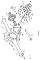
- axle assembly 10 With reference to Figures 1 to 4 , there is shown an axle assembly 10 according to the present invention.
- the axle assembly 10 includes an axle housing 11 and a differential carrier assembly 15.
- the axle housing 11 is defined by a first part 12, a second part 14 and a centre portion 20 (also known as a central bowl).
- the first part 12 includes a first axle tube 16 (in this case a left hand axle tube or left hand housing leg) having a first end 16a (or outboard end) and a second end 16b (or inboard end).
- the first axle tube 16 has a first opening (not shown) at the first end 16a and a second opening (not shown) at the second end 16b.
- the second part 14 includes a second axle tube 18 (in this case a right hand axle tube or right hand housing leg) having a first end 18a (or outboard end) and a second end 18b (or inboard end).
- the second axle tube 18 has a first opening 18c at the first end 18a and a second opening (not shown) at the second end 18b.
- the centre portion 20 is a hollow structure, cast from a metal such as cast iron.
- the centre portion 20 includes an opening 22, which is generally circular.
- the opening 22 is defined by an axle flange 24.
- the axle flange 24 is generally annular and has a generally flat mating surface 26.
- the first mating surface 26 includes twelve fastener holes 28a, 28b, 28c, 28d, 28e, 28f, 28g, 28h, 28i, 28j, 28k, 281, which are spaced circumferentially around the first mating surface 26.
- Each of the fastener holes 28a, 28b, 28c, 28d, 28e, 28f, 28g, 28h, 28i, 28j, 28k, 281 is threaded.
- the axle flange 24 also includes a pair of notches 30a, 30b and a groove 60.
- the pair of notches 30a, 30b extend from the axle flange 24 into the opening 22 of the centre portion 20. Notch 30a is located on an upper portion 24a of the axle flange 24 and notch 30b is located on a lower potion 24b of the axle flange 24.
- the groove 60 is elongate and has a first end 62 and a second end 64.
- the groove 60 is positioned adjacent to the notch 30a on the upper portion 24a of the axle flange 24.
- the first end 62 of the groove 60 is positioned adjacent to fastener hole 28a in the first mating surface 26 and the second end 64 of the groove 60 is positioned adjacent to fastener hole 281 in the first mating surface 26.
- Fastener hole 28a is positioned adjacent to fastener hole 281 around the periphery of the first mating surface 26.
- the groove 60 is less than 200 millimetres long and extends around less than 30 degrees of the first mating surface 26.
- the groove has a depth of approximately 1 millimetre.
- the first axle tube 16 is connected to the centre portion 20 such that the second opening at the second end 16b of the first axle tube 16 opens into the centre portion 20.
- the second axle tube 18 is connected to the centre portion 20 such that the second opening at the second end end 18b of the second axle tube 18 opens into the centre portion 20. In this way, the first and second axle tubes 16, 18 are connected by the centre portion 20.
- the differential carrier assembly 15 has a carrier 32.
- the carrier 32 includes a carrier flange 34 and a mount 40.
- the carrier flange 34 is generally annular and has a second mating surface 36 that is generally flat.
- the second mating surface 36 includes twelve fastener holes 38a, 38b, 38c, 38d, 38e, 38f, 38g, 38h, 38i, 38j, 38k, 381 (only some of which are shown in Figures 1 and 2 ), which are spaced circumferentially around the second mating surface 36.
- Each of the fastener holes 38a, 38b, 38c, 38d, 38e, 38f, 38g, 38h, 38i, 38j, 38k, 381 is threaded.
- the mount 40 supports a crown wheel 42, and a differential 46.
- the differential carrier assembly 15 includes bearings to rotatably support the pinion 44. Further bearings rotatably support the crown wheel 42. These bearings are mounted on mount 40 connected to the differential carrier assembly 15. The crown wheel 42 is in meshing engagement with the pinion 44 in a manner known in the art.
- the centre portion 20 is sized and shaped to accommodate the crown wheel 42, pinion 44, differential 46 and the mount 40.
- the opening 22 is sized and shaped to allow the crown wheel 42, pinion 44, differential 46 and the mount 40 to be passed through the opening 22 and to be received in the centre portion 20.
- the notches 30a, 30b in the axle flange 24 are sized and positioned to provide additional space for the outer diameter of the crown wheel 42, thereby facilitating rotation of the crown wheel 42 when the axle housing 11 and differential carrier assembly 15 are assembled.
- the differential carrier assembly 15 acts as a cover to close the opening 22 of the centre portion 20. In this way, a fluid for example oil (not shown) for lubricating and cooling the crown wheel 42, pinion 44 and differential 46 can be retained within the axle housing 11 and the differential carrier assembly 15.
- the axle assembly 10 is assembled as follows.
- the pinion 44 is mounted on the carrier 32.
- the crown wheel 42, and differential 46 are mounted on the mount 40 of the carrier 32.
- the differential carrier assembly 15, upon which the crown wheel 42, pinion 44 and differential 46 are mounted, is brought into contact with the axle housing 11 such that the crown wheel 42, pinion 44 and differential 46 and the mount 40 are accommodated within the centre portion 20.
- a layer of sealant 54 for example a silicone sealant, such as Dow Corning 7091, Loctite 509, Loctite 518, Permabond LH195 or Permabond LH197, is applied to the first mating surface 26.
- the sealant 54 is applied to fill the groove 60 in the first mating surface 26.
- the second mating surface 36 of the differential housing assembly 14 is brought into contact with the layer of sealant 54 on the first mating surface 26, such that each of the fastener holes 38a, 38b, 38c, 38d, 38e, 38f, 38g, 38h, 38i, 38j, 38k, 381 in the second mating surface 36 is lined up with each of the fastener holes 28a, 28b, 28c, 28d, 28e, 28f, 28g, 28h, 28i, 28j, 28k, 281 in the first mating surface 26.
- the sealant 54 provides a sealing connection between the first mating surface 26 and the second mating surface 36.
- Threaded bolts or studs 48 (only 4 of which are shown in Figures 1 and 2 ) are passed through the fastener holes 38a, 38b, 38c, 38d, 38e, 38f, 38g, 38h, 38i, 38j, 38k, 381 of the second mating surface 36 and the fastener holes 28a, 28b, 28c, 28d, 28e, 28f, 28g, 28h, 28i, 28j, 28k, 281 of the first mating surface 26 in order to secure the carrier assembly 15 to the axle housing 11.
- the threaded bolts 48 have a threaded portion 48a at one of their ends and a second threaded portion 48b at the other of their ends.
- the threaded portion 48a of each of the threaded bolts 48 engages the threaded portion (not shown) of each of the fastener holes 28a, 28b, 28c, 28d, 28e, 28f, 28g, 28h, 28i, 28j, 28k, 281 in the first mating surface 26.
- the threaded portion 48b of each of the threaded bolts 48 engages the threaded portion (not shown) of each of the fastener holes 38a, 38b, 38c, 38d, 38e, 38f, 38g, 38h, 38i, 38j, 38k, 381 in the second mating surface 36.
- the axle assembly 10 is connected to the engine by a drive shaft (not shown) that extends through opening 58 in the differential carrier assembly 15 to the pinion 44.
- the engine (not shown) causes the drive shaft (not shown) and pinion 44 to rotate about a longitudinal axis of the vehicle (not shown).
- the pinion 44 is drivingly engaged to the crown wheel 42 to enable the crown wheel to rotate about an axis which is laterally orientated relative to the vehicle (not shown).
- the left hand drive shaft 50 extends through the opening (not shown) in the left hand axle tube 16 and the right hand drive shaft 52 extends through opening 18c in the right hand axle tube 18.
- the left and right hand drive shafts 50, 52 are caused to rotate in a direction which is laterally orientated relative to the vehicle.
- the left hand drive shaft 50 drives a left hand wheel (not shown) that is rotatably mounted to the axle and the right hand drive shaft 52 drives a right hand wheel rotatably mounted to the axle.
- the differential 46 interacts with the crown wheel 42 to enable the left and right hand drive shafts 50, 52 to rotate at different speeds, for example when the vehicle is driving around a corner.
- axle housing 11 and differential carrier assembly 15 are exposed to vertical, longitudinal and torsional forces caused by movement of the vehicle, the wheels and the axle shafts.
- the elongation of the sealant material is 600% of the thickness of the sealant applied to the first mating surface 26.
- the additional sealant 54 within the groove 60 is able to deform to fill any gaps that might otherwise form between the axle housing 11 and the differential carrier assembly 15 as a result of vertical, longitudinal and torsional forces acting on the axle assembly 10 caused by movement of the vehicle. In this way, leakage of fluid from within the axle assembly is prevented.
- the groove 60 is positioned between adjacent fastener holes so that the sealant 54 is provided at a region of the axle assembly 10 that is not secured or fastened together by threaded bolts or studs 48, i.e. the sealant 54 is provided at a region that is at risk of gaps forming when the axle assembly 10 is exposed to vertical, longitudinal and/or torsional forces.
- the groove 60 is positioned adjacent to the notches 30a, 30b since this is a region of the axle flange 24 where the width of the first mating surface 26 is reduced. This region of the axle flange 24 is at risk of gaps forming when the axle assembly 10 is exposed to vertical, longitudinal and/or torsional forces.
- the centre portion 20 of the axle housing 11 is cast with the groove 60 on the first mating surface 26.
- the groove may be formed by machining.
- the groove 60 is positioned adjacent to the notch 30a on the upper portion 24a of the axle flange 24, with the first end 62 of the groove 60 positioned adjacent to fastener hole 28a and the second end 64 of the groove 60 positioned adjacent to fastener hole 281.
- the fastener hole 28a is adjacent to the fastener hole 281.
- the fastener holes 28a, 281 are positioned next to each other, or contiguous, or physically adjacent, or neighbouring, around the periphery or circumference of the axle flange 24.
- the groove may be positioned adjacent to the notch 30b on the lower portion 24b of the axle flange 24, with the first end 62 of the groove positioned adjacent to fastener hole 28f and the second end 64 of the groove positioned adjacent to fastener hole 28g.
- the fastener hole 28f is adjacent to the fastener hole 28g.
- the fastener holes 28f, 28g are positioned next to each other, or contiguous, or physically adjacent, or neighbouring, around the periphery or circumference of the axle flange 24.
- the groove may be positioned such that the first end 62 is adjacent to one of the fastener holes 28a, 28b, 28c, 28d, 28e, 28f, 28g, 28h, 28i, 28j, 28k, 281 and the second end 64 is adjacent to a second of the fastener holes, the second of the fastener holes being positioned adjacent to, contiguous with or next to, or physically adjacent, or neighbouring, the first of the fastener holes.
- the groove 60 is located on the first mating surface 26 of the axle flange 24.
- the groove may be located on the second mating surface 36 of the differential carrier assembly 15.
- the groove may be machined in the second mating surface 36 of the differential carrier assembly 15. In this way, a differential carrier assembly 15 having a groove may be retrofitted to an existing axle assembly.
- the sealant is a silicone sealant.
- the sealant may include any material suitable for adhering and/or sealing the first mating surface 26 to the second mating surface 36, for example any gasket maker.
- the sealant may be a gasket, for example a gasket including silicone.
- the threaded bolts or studs 48 have threaded portions 48a, 48b at each of their ends. In alternative embodiments, bolts with threads at only one of the ends may be used.
- axle flange 24 and the carrier flange 34 each have twelve fastener holes. In alternative embodiments, any number of fastener holes may be included on each of the axle flange 24 and the carrier flange 34.
Landscapes
- Engineering & Computer Science (AREA)
- Mechanical Engineering (AREA)
- General Engineering & Computer Science (AREA)
- Chemical & Material Sciences (AREA)
- Combustion & Propulsion (AREA)
- Transportation (AREA)
- Retarders (AREA)
- General Details Of Gearings (AREA)
Priority Applications (4)
| Application Number | Priority Date | Filing Date | Title |
|---|---|---|---|
| EP16162665.0A EP3225423A1 (fr) | 2016-03-29 | 2016-03-29 | Ensemble d'essieu |
| US15/467,657 US10309512B2 (en) | 2016-03-29 | 2017-03-23 | Axle assembly |
| CN201710190078.8A CN107234927B (zh) | 2016-03-29 | 2017-03-27 | 车桥组件 |
| BR102017006491-3A BR102017006491A2 (pt) | 2016-03-29 | 2017-03-29 | Montagem de eixo |
Applications Claiming Priority (1)
| Application Number | Priority Date | Filing Date | Title |
|---|---|---|---|
| EP16162665.0A EP3225423A1 (fr) | 2016-03-29 | 2016-03-29 | Ensemble d'essieu |
Publications (1)
| Publication Number | Publication Date |
|---|---|
| EP3225423A1 true EP3225423A1 (fr) | 2017-10-04 |
Family
ID=55640618
Family Applications (1)
| Application Number | Title | Priority Date | Filing Date |
|---|---|---|---|
| EP16162665.0A Withdrawn EP3225423A1 (fr) | 2016-03-29 | 2016-03-29 | Ensemble d'essieu |
Country Status (4)
| Country | Link |
|---|---|
| US (1) | US10309512B2 (fr) |
| EP (1) | EP3225423A1 (fr) |
| CN (1) | CN107234927B (fr) |
| BR (1) | BR102017006491A2 (fr) |
Cited By (1)
| Publication number | Priority date | Publication date | Assignee | Title |
|---|---|---|---|---|
| CN114161879A (zh) * | 2020-09-10 | 2022-03-11 | 盐城市荣南机械制造有限公司 | 一种青储机前驱动桥 |
Families Citing this family (2)
| Publication number | Priority date | Publication date | Assignee | Title |
|---|---|---|---|---|
| US10279625B2 (en) * | 2014-08-15 | 2019-05-07 | Arvinmeritor Technology, Llc | Axel assembly having a bowl cover and a method of manufacture |
| CN110254134B (zh) * | 2019-07-18 | 2024-07-05 | 高邮市北方动力机械有限公司 | 一种新能源汽车驱动桥 |
Citations (5)
| Publication number | Priority date | Publication date | Assignee | Title |
|---|---|---|---|---|
| JPS5612163U (fr) * | 1979-07-10 | 1981-02-02 | ||
| CN101240841A (zh) * | 2007-02-07 | 2008-08-13 | 日产自动车株式会社 | 齿轮单元及防止润滑油飞溅的方法 |
| JP2008224035A (ja) * | 2007-03-12 | 2008-09-25 | Dana Holding Corp | 差動軸受支持体を備える車軸ハウジング |
| US20120142476A1 (en) * | 2009-03-17 | 2012-06-07 | Roberto Gianone | Transmission system |
| US20150087461A1 (en) * | 2013-09-21 | 2015-03-26 | James D. Jackson | Banjo Type Rear Axle Assembly with Drop Out Third Member |
Family Cites Families (37)
| Publication number | Priority date | Publication date | Assignee | Title |
|---|---|---|---|---|
| US1966434A (en) | 1931-05-13 | 1934-07-17 | George A Barker | Lubricating system |
| DE710894C (de) | 1939-03-17 | 1941-09-23 | Rheinmetall Borsig Akt Ges | Umlaufschmierung fuer Achsgetriebe von Kraftfahrzeugen |
| US2242195A (en) | 1940-08-31 | 1941-05-13 | Gen Electric | Geared axle drive |
| US3049928A (en) * | 1959-08-28 | 1962-08-21 | Rockwell Standard Co | Non-drive torque-transmitting axles for transportation vehicles |
| US3800913A (en) | 1972-08-04 | 1974-04-02 | Caterpillar Tractor Co | Recirculating oil system |
| JPS5937462U (ja) | 1982-09-01 | 1984-03-09 | トヨタ自動車株式会社 | アクスルハウジングの潤滑油案内構造 |
| US4683985A (en) | 1985-01-04 | 1987-08-04 | Dresser Industries, Inc. | Lubrication system for a vertical gear unit |
| US4625581A (en) | 1985-01-10 | 1986-12-02 | Ford Motor Company | Automotive component cover |
| US4754847A (en) * | 1986-12-31 | 1988-07-05 | Dana Corporation | Interaxle differential for tandem axle assembly |
| DE4122126C2 (de) * | 1991-07-04 | 1994-09-01 | Viscodrive Gmbh | Antriebsanordnung für ein vierradgetriebenes Kraftfahrzeug |
| US5163226A (en) * | 1991-07-16 | 1992-11-17 | Dana Corporation | Method for forming a banjo-type axle housing |
| TW213883B (fr) | 1992-02-28 | 1993-10-01 | Dana Corp | |
| US5161644A (en) | 1992-04-17 | 1992-11-10 | A. E. Chrow | Lubrication system for tandem axle assembly |
| JP3445391B2 (ja) | 1994-11-11 | 2003-09-08 | 株式会社 神崎高級工機製作所 | トラクタのトランスミッション装置 |
| US5540300A (en) | 1995-01-09 | 1996-07-30 | American Axle & Manufacturing Inc. | Drive axle assembly with lubricant cooling system |
| US5839327A (en) * | 1995-09-18 | 1998-11-24 | American Axle & Manufacturing, Inc. | Drive axle assembly with lubricant cooling system |
| US5637049A (en) * | 1995-10-24 | 1997-06-10 | Vehicular Technologies, Inc. | Locking differential |
| JP3430824B2 (ja) * | 1996-11-01 | 2003-07-28 | 日産自動車株式会社 | 車両の駆動力伝達装置 |
| US6132329A (en) | 1999-07-07 | 2000-10-17 | Meritor Heavy Vehicle Systems, Llc | Axle assembly lubricant temperature reduction apparatus |
| US6729207B2 (en) * | 2002-03-20 | 2004-05-04 | Torque-Traction Technologies, Inc. | Rigid drive axle assembly for motor vehicles |
| US6866605B2 (en) | 2002-06-28 | 2005-03-15 | Caterpillar Inc | Power train assembly |
| US6964320B2 (en) | 2003-01-28 | 2005-11-15 | Torque-Traction Technologies, Inc. | Lubrication arrangement for final drive unit |
| US7121972B2 (en) * | 2003-10-30 | 2006-10-17 | Torque-Traction Technologies, Inc. | Adjustable flange device for cover member in drive axle assembly |
| US7231847B2 (en) | 2005-03-28 | 2007-06-19 | American Axle & Manufacturing, Inc. | Axle assembly with threaded cover pan attachment and method of assembly |
| EP2126354B1 (fr) | 2007-02-27 | 2012-10-17 | Urs Giger | Éolienne et engrenage destiné à celle-ci |
| US7896771B2 (en) * | 2008-03-13 | 2011-03-01 | Honda Motor Company, Ltd. | Differential lock mechanism |
| US8499664B2 (en) * | 2009-09-25 | 2013-08-06 | Caterpillar Inc. | Axle shaft cover plate with bearing assembly |
| US8707826B2 (en) | 2010-01-05 | 2014-04-29 | Chrysler Group Llc | Axle with variable volume sump |
| US8746405B2 (en) | 2010-09-23 | 2014-06-10 | Ford Global Technologies, Llc | Variable lubricant level in a differential sump |
| US9052009B2 (en) | 2010-12-30 | 2015-06-09 | Renault Trucks | Lubrication system for a differential of a driven axle and automotive vehicle comprising such a lubrication system |
| JP5616837B2 (ja) | 2011-03-30 | 2014-10-29 | 株式会社クボタ | 作業車 |
| US8974342B2 (en) | 2012-05-04 | 2015-03-10 | Arvinmeritor Technology, Llc | Axle assembly having a lubricant reservoir module |
| US8858381B2 (en) | 2012-09-12 | 2014-10-14 | Arvinmeritor Technology, Llc | Axle assembly having a lubricant reservoir |
| US8857293B2 (en) * | 2013-03-11 | 2014-10-14 | American Axle & Manufacturing, Inc. | Power transmitting component with multi-part housing assembly having continuous sealing flange |
| US9028358B2 (en) * | 2013-03-15 | 2015-05-12 | American Axle & Manufacturing, Inc. | Disconnecting axle assembly |
| US9927020B2 (en) * | 2014-06-04 | 2018-03-27 | Arvinmeritor Technology, Llc | Axle Assembly |
| US9334945B1 (en) * | 2015-03-12 | 2016-05-10 | GM Global Technology Operations LLC | Vehicle differential assembly |
-
2016
- 2016-03-29 EP EP16162665.0A patent/EP3225423A1/fr not_active Withdrawn
-
2017
- 2017-03-23 US US15/467,657 patent/US10309512B2/en active Active
- 2017-03-27 CN CN201710190078.8A patent/CN107234927B/zh not_active Expired - Fee Related
- 2017-03-29 BR BR102017006491-3A patent/BR102017006491A2/pt not_active Application Discontinuation
Patent Citations (5)
| Publication number | Priority date | Publication date | Assignee | Title |
|---|---|---|---|---|
| JPS5612163U (fr) * | 1979-07-10 | 1981-02-02 | ||
| CN101240841A (zh) * | 2007-02-07 | 2008-08-13 | 日产自动车株式会社 | 齿轮单元及防止润滑油飞溅的方法 |
| JP2008224035A (ja) * | 2007-03-12 | 2008-09-25 | Dana Holding Corp | 差動軸受支持体を備える車軸ハウジング |
| US20120142476A1 (en) * | 2009-03-17 | 2012-06-07 | Roberto Gianone | Transmission system |
| US20150087461A1 (en) * | 2013-09-21 | 2015-03-26 | James D. Jackson | Banjo Type Rear Axle Assembly with Drop Out Third Member |
Cited By (1)
| Publication number | Priority date | Publication date | Assignee | Title |
|---|---|---|---|---|
| CN114161879A (zh) * | 2020-09-10 | 2022-03-11 | 盐城市荣南机械制造有限公司 | 一种青储机前驱动桥 |
Also Published As
| Publication number | Publication date |
|---|---|
| BR102017006491A2 (pt) | 2018-07-31 |
| US20170284526A1 (en) | 2017-10-05 |
| CN107234927B (zh) | 2019-10-29 |
| US10309512B2 (en) | 2019-06-04 |
| CN107234927A (zh) | 2017-10-10 |
Similar Documents
| Publication | Publication Date | Title |
|---|---|---|
| DE102011081119B4 (de) | Dichtungshalteelement für eine Dichtung eines Antriebssystems | |
| US4173269A (en) | Wet brake or clutch | |
| EP3225423A1 (fr) | Ensemble d'essieu | |
| US9434413B1 (en) | Steerable axles transaxle assembly | |
| EP2985165A1 (fr) | Unité de moteur-roue pour véhicule | |
| EP1553330B1 (fr) | Différentiel d'essieu avec un recouvrement estampé | |
| DE102022004575B3 (de) | Elektrischer Radnabenantrieb für ein Kraftfahrzeug | |
| DE102012008652A1 (de) | Getriebemotor und Welle | |
| US20080020888A1 (en) | Producing and maintaining a desired bearing preload in a differential mechanism | |
| US1813819A (en) | Gear wheel | |
| CN104669937B (zh) | 车轴和车轴组件 | |
| WO2014168034A1 (fr) | Unite de moteur dans la roue de vehicule et procede pour assembler un mecanisme d'absorption de deplacement pour cette derniere | |
| US9157518B2 (en) | Seal having integral insert | |
| DE102015210013A1 (de) | Einmassenschwungrad | |
| DE102008044246A1 (de) | Lageranordnung | |
| US4815337A (en) | Locking ring for independent rear suspensions | |
| EP3351403A1 (fr) | Roulement de roue pour un véhicule automobile | |
| CN210507596U (zh) | 滑移装载机轮边支承 | |
| RU2799273C1 (ru) | Редуктор ведущего моста транспортного средства | |
| CN215360772U (zh) | 车桥总成及全地形车 | |
| WO2006096637A1 (fr) | Ensemble d’essieu | |
| US20040216556A1 (en) | Composite differential carrier having cage-type differential carrier frame member | |
| KR101295999B1 (ko) | 감속기의 물 유입 방지 구조 | |
| RU2772625C1 (ru) | Главная передача транспортного средства | |
| CN206268561U (zh) | 一种用于电动驱动型平板闸阀的行程叠合执行器 |
Legal Events
| Date | Code | Title | Description |
|---|---|---|---|
| PUAI | Public reference made under article 153(3) epc to a published international application that has entered the european phase |
Free format text: ORIGINAL CODE: 0009012 |
|
| STAA | Information on the status of an ep patent application or granted ep patent |
Free format text: STATUS: THE APPLICATION HAS BEEN PUBLISHED |
|
| AK | Designated contracting states |
Kind code of ref document: A1 Designated state(s): AL AT BE BG CH CY CZ DE DK EE ES FI FR GB GR HR HU IE IS IT LI LT LU LV MC MK MT NL NO PL PT RO RS SE SI SK SM TR |
|
| AX | Request for extension of the european patent |
Extension state: BA ME |
|
| STAA | Information on the status of an ep patent application or granted ep patent |
Free format text: STATUS: REQUEST FOR EXAMINATION WAS MADE |
|
| 17P | Request for examination filed |
Effective date: 20180328 |
|
| RBV | Designated contracting states (corrected) |
Designated state(s): AL AT BE BG CH CY CZ DE DK EE ES FI FR GB GR HR HU IE IS IT LI LT LU LV MC MK MT NL NO PL PT RO RS SE SI SK SM TR |
|
| STAA | Information on the status of an ep patent application or granted ep patent |
Free format text: STATUS: EXAMINATION IS IN PROGRESS |
|
| 17Q | First examination report despatched |
Effective date: 20180709 |
|
| STAA | Information on the status of an ep patent application or granted ep patent |
Free format text: STATUS: THE APPLICATION IS DEEMED TO BE WITHDRAWN |
|
| 18D | Application deemed to be withdrawn |
Effective date: 20200818 |