EP3225729A1 - Dispositif de liaison et machine comprenant ledit dispositif - Google Patents
Dispositif de liaison et machine comprenant ledit dispositif Download PDFInfo
- Publication number
- EP3225729A1 EP3225729A1 EP17160503.3A EP17160503A EP3225729A1 EP 3225729 A1 EP3225729 A1 EP 3225729A1 EP 17160503 A EP17160503 A EP 17160503A EP 3225729 A1 EP3225729 A1 EP 3225729A1
- Authority
- EP
- European Patent Office
- Prior art keywords
- shaft
- pin
- linking device
- pivoting
- bowed
- Prior art date
- Legal status (The legal status is an assumption and is not a legal conclusion. Google has not performed a legal analysis and makes no representation as to the accuracy of the status listed.)
- Granted
Links
Images





Classifications
-
- D—TEXTILES; PAPER
- D04—BRAIDING; LACE-MAKING; KNITTING; TRIMMINGS; NON-WOVEN FABRICS
- D04B—KNITTING
- D04B15/00—Details of, or auxiliary devices incorporated in, weft knitting machines, restricted to machines of this kind
- D04B15/20—Needle bars
- D04B15/22—Driving devices therefor
-
- D—TEXTILES; PAPER
- D04—BRAIDING; LACE-MAKING; KNITTING; TRIMMINGS; NON-WOVEN FABRICS
- D04B—KNITTING
- D04B9/00—Circular knitting machines with independently-movable needles
- D04B9/40—Circular knitting machines with independently-movable needles with provision for transfer of knitted goods from one machine to another
-
- D—TEXTILES; PAPER
- D04—BRAIDING; LACE-MAKING; KNITTING; TRIMMINGS; NON-WOVEN FABRICS
- D04B—KNITTING
- D04B15/00—Details of, or auxiliary devices incorporated in, weft knitting machines, restricted to machines of this kind
- D04B15/02—Loop-transfer points
-
- D—TEXTILES; PAPER
- D04—BRAIDING; LACE-MAKING; KNITTING; TRIMMINGS; NON-WOVEN FABRICS
- D04B—KNITTING
- D04B39/00—Knitting processes, apparatus or machines not otherwise provided for
- D04B39/08—Sewing machines modified for knitting
-
- D—TEXTILES; PAPER
- D04—BRAIDING; LACE-MAKING; KNITTING; TRIMMINGS; NON-WOVEN FABRICS
- D04B—KNITTING
- D04B9/00—Circular knitting machines with independently-movable needles
- D04B9/42—Circular knitting machines with independently-movable needles specially adapted for producing goods of particular configuration
- D04B9/44—Circular knitting machines with independently-movable needles specially adapted for producing goods of particular configuration elongated tubular articles of small diameter, e.g. coverings for cables
-
- D—TEXTILES; PAPER
- D04—BRAIDING; LACE-MAKING; KNITTING; TRIMMINGS; NON-WOVEN FABRICS
- D04B—KNITTING
- D04B9/00—Circular knitting machines with independently-movable needles
- D04B9/42—Circular knitting machines with independently-movable needles specially adapted for producing goods of particular configuration
- D04B9/46—Circular knitting machines with independently-movable needles specially adapted for producing goods of particular configuration stockings, or portions thereof
-
- D—TEXTILES; PAPER
- D05—SEWING; EMBROIDERING; TUFTING
- D05B—SEWING
- D05B23/00—Sewing apparatus or machines not otherwise provided for
-
- D—TEXTILES; PAPER
- D05—SEWING; EMBROIDERING; TUFTING
- D05B—SEWING
- D05B23/00—Sewing apparatus or machines not otherwise provided for
- D05B23/007—Sewing units for assembling parts of knitted panties or closing the stocking toe part
- D05B23/009—Toe closers
Definitions
- the present invention relates to a linking device for sewing or linking edges of fabric, for example for sewing or linking the toes of stockings or other tubular knitted articles.
- tubular knitted articles for example stockings, socks and tights
- circular knitting machines In some cases, the toe of the tubular knitted article shall be closed by linking or sewing.
- circular knitting machines producing tubular knitted articles with closed toe. These machines are however complex and expensive.
- the tubular knitted article exits from the circular knitting machine with the open toe, and shall be transferred to a sewing or a linking machine.
- a sewing or a linking machine there are devices taking the tubular knitted article from the needle cylinder of the circular knitting machine and transferring it to the sewing machine or the linking machine. Examples of this type of devices are disclosed in WO2004/035894 , WO2010/086708 , US20160024695 .
- the linking devices comprise two bowed needles provided with reciprocating rotary motion for linking by means of two yarns.
- a critical aspect of these devices is the adjustment of the needle position with respect to the members on which the tubular knitted article is engaged, constituted for example by spikes of a linking machine, or by pick-up hooks that are also used to take the tubular knitted article from the needle cylinder of the circular knitting machine (see US20160024695 ).
- the invention relates to a linking device comprising a first bowed needle mounted on a first shaft and a second bowed needle mounted on a second shaft.
- the first shaft and the second shaft are mutually inclined to each other, i.e. they are so arranged that their axes are not parallel to each other. They are controlled in order to pivot reciprocatingly around a pivoting axis of the first shaft and a pivoting axis of the second shaft, respectively.
- the linking device also comprises a first pin rigidly coupled to the first shaft and pivoting therewith, and a second pin rigidly coupled to the second shaft and pivoting therewith.
- a slider connects the first pin and the second pin, being slidingly mounted on both the pins.
- the first pin may be, for instance, parallel to the first shaft and spaced therefrom.
- the second pin may be parallel to the second shaft and spaced therefrom.
- the two shafts are oriented at 90° to each other, i.e. their axes are spaced from each other and lie on different planes, but are orthogonal to each other in a plan view.
- the slider may have two sliding seats, wherein the two pins are slidingly engaged.
- the two seats may be rigidly connected to each other, i.e. the slider may comprise a single rigid component where the two sliding seats for the pins are provided.
- the distance between the two seats i.e. the distance between two parallel axes, containing the axes of the sliding seats, may be equal to the distance between parallel planes containing the pivoting axes of the two shafts.
- the distance between the respective pin and the pivot shaft can be adjusted. It can also be envisaged to provide this adjustment capability for both the bowed needles.
- At least one of the bowed needles, and preferably both needles, are adjustable, with respect to a supporting structure, in a direction parallel to the pivoting axis of the respective shaft.
- one or both the bowed needles lie in a plane orthogonal to the pivoting axis of the respective shaft.
- the invention relates to a linking machine for linking edges of a knitted article comprising engagement members for engaging loops of the knitted article, and a linking device according to the invention.
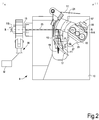
- Figs. 1-5 the linking device is shown in combination with a support system 1 for an article to be linked, for example a sock.
- Number 3 generically indicates engagement members for engaging the knitted article, not shown, that are part of the support system 1.
- the engagement member 3 may comprise hooks 5 and latches 7. It should be understood that, while in the attached figures only some engagement members 3 have been shown just by way of example, actually a full arc of engagement members may be provided, for example an approximately 180° arc of engagement members.
- the system 1 with the engagement members 3 may be designed as disclosed for instance in US20160024695 . In other embodiments, the system 1 may be constituted by spikes of a linking machine, as described for example in WO2004/035894 .
- Reference number 9 indicates the linking device as a whole. It comprises a supporting structure 10, on which a first shaft 13 and a second shaft 15 are mounted.
- the first shaft 13 is provided with a pivoting, i.e. reciprocating, angular motion around a pivoting axis A-A
- the second shaft 15 is provided with a pivoting, i.e. reciprocating, angular motion around a pivoting axis B-B.
- the two shafts 13 and 15, and therefore the two axes A-A and B-B are directed at 90° with respect to each other, but they lie on two distinct parallel planes arranged at a distance D3, as shown in Figs. 1 and 8B .
- a first bowed needle 17 is integral with the first shaft 13, and a second bowed needle 19, below also called “crochet needle", is integral with the second shaft 15.
- the first bowed needle 17 moves on a plane orthogonal to the axis A-A when the first shaft 13 reciprocatingly pivots around the axis A-A
- the second bowed needle, or crochet needle, 19 moves on a plane orthogonal to the axis B-B when the second shaft 15 reciprocatingly pivots around the axis B-B.
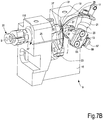
- first bowed needle 17 is integral with the first shaft 13 by means of a first arm 21, while the second bowed needle 19 is integral with the second shaft 15 by means of a second arm 23 (see also the sequence in Figs. 7A-7C ).
- a first yarn Y1 is fed to the first bowed needle 17, while a second yarn Y2 is fed to the second bowed needle 19.
- the first bowed needle 17 and the second bowed needle 19 cooperate with each other and with a stationary finger 25, that may be supported by the supporting structure 10 in a way not shown for the sake of drawing simplicity.
- the pivoting motion of the first bowed needle 17 and of the second bowed needle 19, cooperating with each other and with the finger 25, allows to form a series of chain stitches for linking edges of fabric held adjacent to each other by means of the members 3, 5.
- the way for making the sewing or linking stitches is known to those skilled in the art and does not require to be described herein.
- the pivoting motion of the first bowed needle 17 is synchronized with the motion of the second bowed needle, or crochet needle, 19, and these motions are represented in the sequence of Figs. 7A-7C .
- This sequence shows a portion of the sequence of motion of the bowed needles 17, 19, and precisely the sequence when the first bowed needle 17 and the second bowed needle, or crochet needle, 19 pivot from respective positions of maximum lifting ( Fig.
- the complete cycle of motion of the bowed needles 17, 19 comprises the reverse sequence (from Fig. 7C to Fig. 7A ), when both the bowed needles 17, 19 move upwards from the position of maximum lowering to the position of maximum lifting.
- the movement may be imparted by means of an actuator, for example an electronically controlled electric motor, schematically indicated with M only in Fig. 2 , which can be connected to the second shaft 15 by means of a suitable mechanical transmission, for example by means of a rod-crank system 30.
- the rod-crank system 30 changes the continuous rotation motion of the motor M into a reciprocating pivoting motion of the second shaft 15 and of the second bowed needle, or crochet needle, 19 around the axis B-B.
- the motion is transmitted to the first shaft 13 and to the first bowed needle 17 by means of a mechanism described below.
- the motor M may be connected, by means of a suitable mechanical transmission, to the first shaft 13 instead of being connected to the second shaft 15.
- a first pin 27 is integral with the first shaft 13, the pin being carried by a first auxiliary arm 29.
- the first auxiliary arm 29 is rotatingly coupled to the first shaft 13, i.e. it pivots integrally therewith.
- the two arms 29 and 21 are angularly spaced from each other.
- the first pin 27 is parallel to the first shaft 13.
- a second pin 31 is integral with the second shaft 15.
- the second pin may be carried by a second auxiliary arm 33, rotatingly constrained with the second shaft 15, i.e. the second pin 31 pivots integrally with the second shaft 15.
- the second auxiliary arm 33 is angularly spaced from the second arm 23 constraining the second bowed needle 19 to the second shaft 15.
- the second pin 31 is parallel to the second shaft 15.
- the first pin 27 and the second pin 31 are mechanically coupled to each other by means of a slider 35.
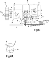
- the slider 35 may comprise two sliding seats 36, 38 ( Fig. 6A ), oriented at 90° with respect to each other but lying on two distinct planes.
- the first pin 27 is inserted in the sliding seat 36, while the second pin 31 is inserted in the seat 38.
- the distance between two parallel planes containing the axes of the sliding seats (and therefore the axes of the first pin 27 and of the second pin 31) is indicated with D4 in Figs. 2 and 8B .
- the distance D4 between the parallel planes containing the axis of the first pin 27 and the axis of the second pin 31, corresponding to the distance between the axis of the seats 36 and the axis of the seat 38, is equal to the distance D3 between the parallel planes containing the pivoting axis A-A of the first shaft 13 and the pivoting axis B-B of the second shaft 15.
- the two bowed needles 17 and 19 perform the same movements.
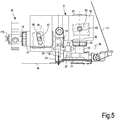
- FIG. 5 and 6 The possibility of adjusting the position of the bowed needles 17, 19 with respect to the reciprocating pivoting axis A-A and to the reciprocating pivoting axis B-B is shown in detail in Figs. 5 and 6 .
- each of the two bowed needles 17, 19 is shown in two different axial positions.
- the adjustment of the position of the bowed needles 17 is performed according to the arrow fA, while the adjustment of the position of the bowed needle 19 is performed according to the arrow fB, in each case in a direction parallel to the respective pivoting axis A-A and B-B.
- An adjustment arrangement may be provided for independently adjusting the position of each bowed needle 17, 19 in the direction of the axis A-A and of the axis B-B respectively.
- Figs. 5 and 6 show a possible embodiment of this adjustment arrangement.
- the first shaft 13 may be pivotingly supported in a first sleeve 41 housed in the supporting structure 10.
- the first sleeve 41 has a helical groove 43 where a fastening screw engages. By tightening the fastening screw 45, the first sleeve 41 is axially and torsionally blocked in the supporting structure 10. By loosening the fastening screw 45, it is possible to rotate the first sleeve 41 around the axis A-A.
- the rotation of the first sleeve 41 around the axis A-A causes a corresponding axial movement of the first sleeve 41 according to the arrow fA in the housing seat of the supporting structure 10.
- the translation of the first sleeve 41 according to fA causes a corresponding translation of the first shaft 13 and of the first bowed needle 17 according to the arrow fA.
- the adjustment of the position of the first bowed needle 17 according to the direction of the axis A-A is performed as follows: the fastening screw 45 is loosed, while keeping it engaged in the helical groove 43. The first sleeve 41 rotates around the axis A-A until the first bowed needle 17 achieves the desired position, and lastly the fastening screw 45 is tightening again until the first sleeve 41 is blocked in the selected axial position.
- the adjustment of the position of the second bowed needle, or crochet needle, 19 in the direction of the axis B-B is performed with substantially the same arrangement.
- a second sleeve 47 is provided, housed in a seat of the supporting structure 10 and provided with a helical groove 49.
- a fastening screw 51 engages the helical groove 49.
- the adjustment of the position of the second bowed needle 19 according to the arrow fB is performed similarly to what has been already described with reference to the first bowed needle 17.
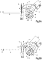
- a further adjustment possibility may be provided for the linking device 9.
- This further adjustment possibility is clearly shown in Figs. 8A and 8B , showing a view of the two bowed needles 17, 19, of the respective shafts 13, 15, of the slider 35 and of the pins 27, 31, according to the axis A-A.
- the supporting structure 10 and the sleeves 41 and 47 have been omitted.
- the distance between the first pin 27 and the axis A-A of the first shaft 13 is adjustable. This distance is indicated with D1 in Fig. 8A and with D2 in Fig. 8B , wherein D1 is shorter than D2.
- D1 is shorter than D2.
- an adjustment screw 57 and a pre-load spring 59 may be provided.
- the pre-load spring 59 pushes the first auxiliary arm 28 towards the position of minimum distance of the first pin 27 with respect to the axis A-A.
- the adjustment screw 57 the position of the pin 27 with respect to the axis A-A can be adjusted by pressing or releasing the pre-load spring 59, as it is visible by comparing Figs. 8A and 8B . This adjustment allows to modify the pivoting angle of one bowed needle with respect to the other bowed needle.
- the distance between the second pin 31 and the axis B-B can be adjusted, in combination with or as an alternative to the adjustment of the distance between the first pin 27 and the axis A-A.
Landscapes
- Engineering & Computer Science (AREA)
- Textile Engineering (AREA)
- Knitting Machines (AREA)
- Sewing Machines And Sewing (AREA)
- Ultra Sonic Daignosis Equipment (AREA)
Applications Claiming Priority (1)
| Application Number | Priority Date | Filing Date | Title |
|---|---|---|---|
| ITUA2016A002241A ITUA20162241A1 (it) | 2016-04-01 | 2016-04-01 | Dispositivo di rimagliatura e macchina comprendente detto dispositivo |
Publications (2)
| Publication Number | Publication Date |
|---|---|
| EP3225729A1 true EP3225729A1 (fr) | 2017-10-04 |
| EP3225729B1 EP3225729B1 (fr) | 2019-05-01 |
Family
ID=56296992
Family Applications (1)
| Application Number | Title | Priority Date | Filing Date |
|---|---|---|---|
| EP17160503.3A Active EP3225729B1 (fr) | 2016-04-01 | 2017-03-13 | Dispositif de liaison et machine comprenant ledit dispositif |
Country Status (9)
| Country | Link |
|---|---|
| US (1) | US10190241B2 (fr) |
| EP (1) | EP3225729B1 (fr) |
| KR (1) | KR102272289B1 (fr) |
| CN (1) | CN107268166B (fr) |
| BR (1) | BR102017006562B1 (fr) |
| IT (1) | ITUA20162241A1 (fr) |
| MX (1) | MX366898B (fr) |
| TR (1) | TR201911150T4 (fr) |
| TW (1) | TWI724131B (fr) |
Cited By (1)
| Publication number | Priority date | Publication date | Assignee | Title |
|---|---|---|---|---|
| IT201900012417A1 (it) * | 2019-07-19 | 2021-01-19 | Da Kong Entpr Co Ltd | Dispositivo di cucitura o di rimagliatura per la chiusura di un manufatto tubolare a maglia |
Families Citing this family (3)
| Publication number | Priority date | Publication date | Assignee | Title |
|---|---|---|---|---|
| JP6395135B2 (ja) * | 2015-04-15 | 2018-09-26 | ヤマトミシン製造株式会社 | ミシン |
| ITUA20162241A1 (it) * | 2016-04-01 | 2017-10-01 | Staeubli Italia S P A | Dispositivo di rimagliatura e macchina comprendente detto dispositivo |
| IT202100011552A1 (it) * | 2021-05-06 | 2022-11-06 | Santex Rimar Group S R L | Macchina rimagliatrice munita di una guida perfezionata per allineare tra loro due lembi di tessuto per essere rimagliati |
Citations (6)
| Publication number | Priority date | Publication date | Assignee | Title |
|---|---|---|---|---|
| CH264876A (de) * | 1948-02-09 | 1949-11-15 | Henkel Max | Verfahren und Vorrichtung zum Herstellen einer Saumnaht. |
| US2515740A (en) * | 1947-11-14 | 1950-07-18 | Singer Mfg Co | Stitch-forming mechanism for sewing machines |
| WO2004035894A1 (fr) | 2002-10-21 | 2004-04-29 | Fabritex S.R.L. | Procede et appareil de raccordement des bords d'un article tricote tubulaire |
| WO2009144049A1 (fr) * | 2008-05-30 | 2009-12-03 | Lonati S.P.A. | Tête de couture ou de remaillage, en particulier pour la fermeture automatique d'articles tricotés tubulaires à une extrémité axiale de ceux-ci |
| WO2010086708A1 (fr) | 2009-01-30 | 2010-08-05 | N.T.A. S.R.L. | Dispositif pour étirer une chaussette à partir d'une machine cylindrique pour la production d'un produit tubulaire avec extrémité fermée |
| US20160024695A1 (en) | 2013-04-12 | 2016-01-28 | Staubli Italia S.P.A. | Method and machine for knitting tubular knitted articles |
Family Cites Families (11)
| Publication number | Priority date | Publication date | Assignee | Title |
|---|---|---|---|---|
| IT1173667B (it) * | 1983-05-06 | 1987-06-24 | Rockwell Rimoldi Spa | Crochet per macchine per cucire |
| DE4343421C1 (de) * | 1993-12-18 | 1995-02-09 | Union Special Gmbh | Greiferantrieb für eine Kettenstichnähmaschine |
| JP2995464B2 (ja) * | 1998-05-15 | 1999-12-27 | 株式会社島精機製作所 | 横編機における編目ループの預け置き装置 |
| JP4025512B2 (ja) * | 2000-05-12 | 2007-12-19 | 丸善産業株式会社 | 靴下のつま先縫製方法と装置 |
| US6779472B1 (en) * | 2003-03-25 | 2004-08-24 | Sara Lee Corporation | Hosiery toe closing apparatus and method |
| GB0315178D0 (en) * | 2003-06-28 | 2003-08-06 | Ardmel Automation Ltd | Seaming apparatus |
| ITMI20111683A1 (it) * | 2011-09-19 | 2013-03-20 | Lonati Spa | Procedimento per la preparazione di un manufatto tubolare del tipo calza o simile al prelievo automatizzato al termine della sua formazione su una macchina circolare a doppio cilindro con almeno una alimentazione o caduta e macchina circolare a doppi |
| US8443633B1 (en) * | 2012-09-05 | 2013-05-21 | Da Kong Enterprise Co., Ltd. | Apparatus and method for transferring loops from the knitting machine needle |
| TWI509121B (zh) * | 2013-11-15 | 2015-11-21 | Da Kong Entpr Co Ltd | Socks sewing device |
| TWI589747B (zh) * | 2015-03-04 | 2017-07-01 | Coil folding device | |
| ITUA20162241A1 (it) * | 2016-04-01 | 2017-10-01 | Staeubli Italia S P A | Dispositivo di rimagliatura e macchina comprendente detto dispositivo |
-
2016
- 2016-04-01 IT ITUA2016A002241A patent/ITUA20162241A1/it unknown
-
2017
- 2017-03-13 TR TR2019/11150T patent/TR201911150T4/tr unknown
- 2017-03-13 EP EP17160503.3A patent/EP3225729B1/fr active Active
- 2017-03-14 TW TW106108329A patent/TWI724131B/zh active
- 2017-03-27 US US15/469,739 patent/US10190241B2/en active Active
- 2017-03-29 KR KR1020170039920A patent/KR102272289B1/ko active Active
- 2017-03-30 BR BR102017006562-6A patent/BR102017006562B1/pt active IP Right Grant
- 2017-03-30 MX MX2017004227A patent/MX366898B/es active IP Right Grant
- 2017-03-31 CN CN201710204463.3A patent/CN107268166B/zh active Active
Patent Citations (6)
| Publication number | Priority date | Publication date | Assignee | Title |
|---|---|---|---|---|
| US2515740A (en) * | 1947-11-14 | 1950-07-18 | Singer Mfg Co | Stitch-forming mechanism for sewing machines |
| CH264876A (de) * | 1948-02-09 | 1949-11-15 | Henkel Max | Verfahren und Vorrichtung zum Herstellen einer Saumnaht. |
| WO2004035894A1 (fr) | 2002-10-21 | 2004-04-29 | Fabritex S.R.L. | Procede et appareil de raccordement des bords d'un article tricote tubulaire |
| WO2009144049A1 (fr) * | 2008-05-30 | 2009-12-03 | Lonati S.P.A. | Tête de couture ou de remaillage, en particulier pour la fermeture automatique d'articles tricotés tubulaires à une extrémité axiale de ceux-ci |
| WO2010086708A1 (fr) | 2009-01-30 | 2010-08-05 | N.T.A. S.R.L. | Dispositif pour étirer une chaussette à partir d'une machine cylindrique pour la production d'un produit tubulaire avec extrémité fermée |
| US20160024695A1 (en) | 2013-04-12 | 2016-01-28 | Staubli Italia S.P.A. | Method and machine for knitting tubular knitted articles |
Cited By (1)
| Publication number | Priority date | Publication date | Assignee | Title |
|---|---|---|---|---|
| IT201900012417A1 (it) * | 2019-07-19 | 2021-01-19 | Da Kong Entpr Co Ltd | Dispositivo di cucitura o di rimagliatura per la chiusura di un manufatto tubolare a maglia |
Also Published As
| Publication number | Publication date |
|---|---|
| TWI724131B (zh) | 2021-04-11 |
| TW201738423A (zh) | 2017-11-01 |
| TR201911150T4 (tr) | 2019-08-21 |
| CN107268166B (zh) | 2020-08-28 |
| EP3225729B1 (fr) | 2019-05-01 |
| BR102017006562B1 (pt) | 2022-08-09 |
| BR102017006562A2 (pt) | 2017-10-10 |
| KR102272289B1 (ko) | 2021-07-02 |
| US10190241B2 (en) | 2019-01-29 |
| MX366898B (es) | 2019-07-30 |
| KR20170113353A (ko) | 2017-10-12 |
| US20170283997A1 (en) | 2017-10-05 |
| ITUA20162241A1 (it) | 2017-10-01 |
| CN107268166A (zh) | 2017-10-20 |
| MX2017004227A (es) | 2018-08-16 |
Similar Documents
| Publication | Publication Date | Title |
|---|---|---|
| EP3225729B1 (fr) | Dispositif de liaison et machine comprenant ledit dispositif | |
| US7320233B2 (en) | Control device for linear knitting machines thread-guide bars | |
| KR20130024854A (ko) | 쌍침 재봉기 | |
| US3285210A (en) | Looper drive for chain stitch sewing machines | |
| KR101266348B1 (ko) | 재봉틀의 이송장치 | |
| US4344307A (en) | Thread control means in a textile machine | |
| JPH03227439A (ja) | 編機のプランジャ針制御装置 | |
| JP4228368B2 (ja) | ミシン | |
| US6186187B1 (en) | Cloth moving type pile forming apparatus | |
| KR20080000510A (ko) | 단추달이 재봉기 | |
| TWI461583B (zh) | On the stitching sewing machine | |
| CN111989432B (zh) | 用于纺织品制造的组件及相关方法 | |
| CN114080476B (zh) | 具有用于针板的成圈三角的偏置系统的圆形针织机 | |
| CN102828338A (zh) | 一种电脑针织圆机调线装置的传动机构 | |
| CZ297999B6 (cs) | Zarízení pro ovládání hustotového zámku jehel na pletacím stroji | |
| KR100609202B1 (ko) | 북이 없는 직조기의 매듭형성장치 | |
| EP2508663B1 (fr) | Machine à coudre avec un dispositif pour échanger la bobine | |
| GB2039544A (en) | Circular warp knitting machine | |
| US1289126A (en) | Mechanical movement. | |
| CZ26538U1 (cs) | Zařízení k synchronizaci vzájemného pohybu jehelní tyče a chapače šicího stroje | |
| GB550790A (en) | Improvements in or relating to means for controlling yarns in knitting machines |
Legal Events
| Date | Code | Title | Description |
|---|---|---|---|
| PUAI | Public reference made under article 153(3) epc to a published international application that has entered the european phase |
Free format text: ORIGINAL CODE: 0009012 |
|
| STAA | Information on the status of an ep patent application or granted ep patent |
Free format text: STATUS: THE APPLICATION HAS BEEN PUBLISHED |
|
| AK | Designated contracting states |
Kind code of ref document: A1 Designated state(s): AL AT BE BG CH CY CZ DE DK EE ES FI FR GB GR HR HU IE IS IT LI LT LU LV MC MK MT NL NO PL PT RO RS SE SI SK SM TR |
|
| AX | Request for extension of the european patent |
Extension state: BA ME |
|
| STAA | Information on the status of an ep patent application or granted ep patent |
Free format text: STATUS: REQUEST FOR EXAMINATION WAS MADE |
|
| 17P | Request for examination filed |
Effective date: 20180323 |
|
| RBV | Designated contracting states (corrected) |
Designated state(s): AL AT BE BG CH CY CZ DE DK EE ES FI FR GB GR HR HU IE IS IT LI LT LU LV MC MK MT NL NO PL PT RO RS SE SI SK SM TR |
|
| GRAP | Despatch of communication of intention to grant a patent |
Free format text: ORIGINAL CODE: EPIDOSNIGR1 |
|
| STAA | Information on the status of an ep patent application or granted ep patent |
Free format text: STATUS: GRANT OF PATENT IS INTENDED |
|
| INTG | Intention to grant announced |
Effective date: 20181001 |
|
| GRAS | Grant fee paid |
Free format text: ORIGINAL CODE: EPIDOSNIGR3 |
|
| GRAA | (expected) grant |
Free format text: ORIGINAL CODE: 0009210 |
|
| STAA | Information on the status of an ep patent application or granted ep patent |
Free format text: STATUS: THE PATENT HAS BEEN GRANTED |
|
| AK | Designated contracting states |
Kind code of ref document: B1 Designated state(s): AL AT BE BG CH CY CZ DE DK EE ES FI FR GB GR HR HU IE IS IT LI LT LU LV MC MK MT NL NO PL PT RO RS SE SI SK SM TR |
|
| REG | Reference to a national code |
Ref country code: GB Ref legal event code: FG4D |
|
| REG | Reference to a national code |
Ref country code: CH Ref legal event code: EP Ref country code: AT Ref legal event code: REF Ref document number: 1127016 Country of ref document: AT Kind code of ref document: T Effective date: 20190515 |
|
| REG | Reference to a national code |
Ref country code: DE Ref legal event code: R096 Ref document number: 602017003565 Country of ref document: DE |
|
| REG | Reference to a national code |
Ref country code: IE Ref legal event code: FG4D |
|
| REG | Reference to a national code |
Ref country code: NL Ref legal event code: MP Effective date: 20190501 |
|
| REG | Reference to a national code |
Ref country code: LT Ref legal event code: MG4D |
|
| PG25 | Lapsed in a contracting state [announced via postgrant information from national office to epo] |
Ref country code: FI Free format text: LAPSE BECAUSE OF FAILURE TO SUBMIT A TRANSLATION OF THE DESCRIPTION OR TO PAY THE FEE WITHIN THE PRESCRIBED TIME-LIMIT Effective date: 20190501 Ref country code: NO Free format text: LAPSE BECAUSE OF FAILURE TO SUBMIT A TRANSLATION OF THE DESCRIPTION OR TO PAY THE FEE WITHIN THE PRESCRIBED TIME-LIMIT Effective date: 20190801 Ref country code: ES Free format text: LAPSE BECAUSE OF FAILURE TO SUBMIT A TRANSLATION OF THE DESCRIPTION OR TO PAY THE FEE WITHIN THE PRESCRIBED TIME-LIMIT Effective date: 20190501 Ref country code: PT Free format text: LAPSE BECAUSE OF FAILURE TO SUBMIT A TRANSLATION OF THE DESCRIPTION OR TO PAY THE FEE WITHIN THE PRESCRIBED TIME-LIMIT Effective date: 20190901 Ref country code: SE Free format text: LAPSE BECAUSE OF FAILURE TO SUBMIT A TRANSLATION OF THE DESCRIPTION OR TO PAY THE FEE WITHIN THE PRESCRIBED TIME-LIMIT Effective date: 20190501 Ref country code: AL Free format text: LAPSE BECAUSE OF FAILURE TO SUBMIT A TRANSLATION OF THE DESCRIPTION OR TO PAY THE FEE WITHIN THE PRESCRIBED TIME-LIMIT Effective date: 20190501 Ref country code: NL Free format text: LAPSE BECAUSE OF FAILURE TO SUBMIT A TRANSLATION OF THE DESCRIPTION OR TO PAY THE FEE WITHIN THE PRESCRIBED TIME-LIMIT Effective date: 20190501 Ref country code: LT Free format text: LAPSE BECAUSE OF FAILURE TO SUBMIT A TRANSLATION OF THE DESCRIPTION OR TO PAY THE FEE WITHIN THE PRESCRIBED TIME-LIMIT Effective date: 20190501 Ref country code: HR Free format text: LAPSE BECAUSE OF FAILURE TO SUBMIT A TRANSLATION OF THE DESCRIPTION OR TO PAY THE FEE WITHIN THE PRESCRIBED TIME-LIMIT Effective date: 20190501 |
|
| PG25 | Lapsed in a contracting state [announced via postgrant information from national office to epo] |
Ref country code: BG Free format text: LAPSE BECAUSE OF FAILURE TO SUBMIT A TRANSLATION OF THE DESCRIPTION OR TO PAY THE FEE WITHIN THE PRESCRIBED TIME-LIMIT Effective date: 20190801 Ref country code: LV Free format text: LAPSE BECAUSE OF FAILURE TO SUBMIT A TRANSLATION OF THE DESCRIPTION OR TO PAY THE FEE WITHIN THE PRESCRIBED TIME-LIMIT Effective date: 20190501 Ref country code: RS Free format text: LAPSE BECAUSE OF FAILURE TO SUBMIT A TRANSLATION OF THE DESCRIPTION OR TO PAY THE FEE WITHIN THE PRESCRIBED TIME-LIMIT Effective date: 20190501 |
|
| REG | Reference to a national code |
Ref country code: AT Ref legal event code: MK05 Ref document number: 1127016 Country of ref document: AT Kind code of ref document: T Effective date: 20190501 |
|
| PG25 | Lapsed in a contracting state [announced via postgrant information from national office to epo] |
Ref country code: IS Free format text: LAPSE BECAUSE OF FAILURE TO SUBMIT A TRANSLATION OF THE DESCRIPTION OR TO PAY THE FEE WITHIN THE PRESCRIBED TIME-LIMIT Effective date: 20190901 |
|
| PG25 | Lapsed in a contracting state [announced via postgrant information from national office to epo] |
Ref country code: SK Free format text: LAPSE BECAUSE OF FAILURE TO SUBMIT A TRANSLATION OF THE DESCRIPTION OR TO PAY THE FEE WITHIN THE PRESCRIBED TIME-LIMIT Effective date: 20190501 Ref country code: EE Free format text: LAPSE BECAUSE OF FAILURE TO SUBMIT A TRANSLATION OF THE DESCRIPTION OR TO PAY THE FEE WITHIN THE PRESCRIBED TIME-LIMIT Effective date: 20190501 Ref country code: CZ Free format text: LAPSE BECAUSE OF FAILURE TO SUBMIT A TRANSLATION OF THE DESCRIPTION OR TO PAY THE FEE WITHIN THE PRESCRIBED TIME-LIMIT Effective date: 20190501 Ref country code: RO Free format text: LAPSE BECAUSE OF FAILURE TO SUBMIT A TRANSLATION OF THE DESCRIPTION OR TO PAY THE FEE WITHIN THE PRESCRIBED TIME-LIMIT Effective date: 20190501 Ref country code: AT Free format text: LAPSE BECAUSE OF FAILURE TO SUBMIT A TRANSLATION OF THE DESCRIPTION OR TO PAY THE FEE WITHIN THE PRESCRIBED TIME-LIMIT Effective date: 20190501 Ref country code: DK Free format text: LAPSE BECAUSE OF FAILURE TO SUBMIT A TRANSLATION OF THE DESCRIPTION OR TO PAY THE FEE WITHIN THE PRESCRIBED TIME-LIMIT Effective date: 20190501 |
|
| REG | Reference to a national code |
Ref country code: DE Ref legal event code: R097 Ref document number: 602017003565 Country of ref document: DE |
|
| PG25 | Lapsed in a contracting state [announced via postgrant information from national office to epo] |
Ref country code: SM Free format text: LAPSE BECAUSE OF FAILURE TO SUBMIT A TRANSLATION OF THE DESCRIPTION OR TO PAY THE FEE WITHIN THE PRESCRIBED TIME-LIMIT Effective date: 20190501 |
|
| PLBE | No opposition filed within time limit |
Free format text: ORIGINAL CODE: 0009261 |
|
| STAA | Information on the status of an ep patent application or granted ep patent |
Free format text: STATUS: NO OPPOSITION FILED WITHIN TIME LIMIT |
|
| 26N | No opposition filed |
Effective date: 20200204 |
|
| PG25 | Lapsed in a contracting state [announced via postgrant information from national office to epo] |
Ref country code: PL Free format text: LAPSE BECAUSE OF FAILURE TO SUBMIT A TRANSLATION OF THE DESCRIPTION OR TO PAY THE FEE WITHIN THE PRESCRIBED TIME-LIMIT Effective date: 20190501 |
|
| PG25 | Lapsed in a contracting state [announced via postgrant information from national office to epo] |
Ref country code: SI Free format text: LAPSE BECAUSE OF FAILURE TO SUBMIT A TRANSLATION OF THE DESCRIPTION OR TO PAY THE FEE WITHIN THE PRESCRIBED TIME-LIMIT Effective date: 20190501 |
|
| PG25 | Lapsed in a contracting state [announced via postgrant information from national office to epo] |
Ref country code: MC Free format text: LAPSE BECAUSE OF FAILURE TO SUBMIT A TRANSLATION OF THE DESCRIPTION OR TO PAY THE FEE WITHIN THE PRESCRIBED TIME-LIMIT Effective date: 20190501 |
|
| REG | Reference to a national code |
Ref country code: CH Ref legal event code: PL |
|
| REG | Reference to a national code |
Ref country code: BE Ref legal event code: MM Effective date: 20200331 |
|
| PG25 | Lapsed in a contracting state [announced via postgrant information from national office to epo] |
Ref country code: LU Free format text: LAPSE BECAUSE OF NON-PAYMENT OF DUE FEES Effective date: 20200313 |
|
| PG25 | Lapsed in a contracting state [announced via postgrant information from national office to epo] |
Ref country code: IE Free format text: LAPSE BECAUSE OF NON-PAYMENT OF DUE FEES Effective date: 20200313 Ref country code: LI Free format text: LAPSE BECAUSE OF NON-PAYMENT OF DUE FEES Effective date: 20200331 Ref country code: FR Free format text: LAPSE BECAUSE OF NON-PAYMENT OF DUE FEES Effective date: 20200331 Ref country code: CH Free format text: LAPSE BECAUSE OF NON-PAYMENT OF DUE FEES Effective date: 20200331 |
|
| PG25 | Lapsed in a contracting state [announced via postgrant information from national office to epo] |
Ref country code: BE Free format text: LAPSE BECAUSE OF NON-PAYMENT OF DUE FEES Effective date: 20200331 |
|
| GBPC | Gb: european patent ceased through non-payment of renewal fee |
Effective date: 20210313 |
|
| PG25 | Lapsed in a contracting state [announced via postgrant information from national office to epo] |
Ref country code: GB Free format text: LAPSE BECAUSE OF NON-PAYMENT OF DUE FEES Effective date: 20210313 |
|
| PG25 | Lapsed in a contracting state [announced via postgrant information from national office to epo] |
Ref country code: MT Free format text: LAPSE BECAUSE OF FAILURE TO SUBMIT A TRANSLATION OF THE DESCRIPTION OR TO PAY THE FEE WITHIN THE PRESCRIBED TIME-LIMIT Effective date: 20190501 Ref country code: CY Free format text: LAPSE BECAUSE OF FAILURE TO SUBMIT A TRANSLATION OF THE DESCRIPTION OR TO PAY THE FEE WITHIN THE PRESCRIBED TIME-LIMIT Effective date: 20190501 |
|
| PG25 | Lapsed in a contracting state [announced via postgrant information from national office to epo] |
Ref country code: MK Free format text: LAPSE BECAUSE OF FAILURE TO SUBMIT A TRANSLATION OF THE DESCRIPTION OR TO PAY THE FEE WITHIN THE PRESCRIBED TIME-LIMIT Effective date: 20190501 |
|
| PG25 | Lapsed in a contracting state [announced via postgrant information from national office to epo] |
Ref country code: GR Free format text: LAPSE BECAUSE OF FAILURE TO SUBMIT A TRANSLATION OF THE DESCRIPTION OR TO PAY THE FEE WITHIN THE PRESCRIBED TIME-LIMIT Effective date: 20190501 |
|
| REG | Reference to a national code |
Ref country code: DE Ref legal event code: R081 Ref document number: 602017003565 Country of ref document: DE Owner name: SANTONI (SHANGHAI) KNITTING MACHINERY CO., LTD, CN Free format text: FORMER OWNER: STAEUBLI ITALIA S.P.A., CARATE BRIANZA, IT |
|
| PGFP | Annual fee paid to national office [announced via postgrant information from national office to epo] |
Ref country code: DE Payment date: 20260211 Year of fee payment: 10 |
|
| PGFP | Annual fee paid to national office [announced via postgrant information from national office to epo] |
Ref country code: IT Payment date: 20260220 Year of fee payment: 10 |
|
| PGFP | Annual fee paid to national office [announced via postgrant information from national office to epo] |
Ref country code: TR Payment date: 20260311 Year of fee payment: 10 |