EP3226029A1 - Scanner à laser avec projecteur référencé - Google Patents
Scanner à laser avec projecteur référencé Download PDFInfo
- Publication number
- EP3226029A1 EP3226029A1 EP16163039.7A EP16163039A EP3226029A1 EP 3226029 A1 EP3226029 A1 EP 3226029A1 EP 16163039 A EP16163039 A EP 16163039A EP 3226029 A1 EP3226029 A1 EP 3226029A1
- Authority
- EP
- European Patent Office
- Prior art keywords
- projector
- scene
- laser scanner
- laser
- axis
- Prior art date
- Legal status (The legal status is an assumption and is not a legal conclusion. Google has not performed a legal analysis and makes no representation as to the accuracy of the status listed.)
- Withdrawn
Links
- 230000005540 biological transmission Effects 0.000 claims abstract description 14
- 238000000034 method Methods 0.000 claims description 22
- 230000003190 augmentative effect Effects 0.000 claims description 16
- 230000003287 optical effect Effects 0.000 claims description 11
- 239000011159 matrix material Substances 0.000 claims description 4
- 238000010276 construction Methods 0.000 description 13
- 238000011960 computer-aided design Methods 0.000 description 11
- 230000001419 dependent effect Effects 0.000 description 6
- 230000001276 controlling effect Effects 0.000 description 4
- 239000007787 solid Substances 0.000 description 4
- 238000005259 measurement Methods 0.000 description 3
- 230000000007 visual effect Effects 0.000 description 3
- 238000012986 modification Methods 0.000 description 2
- 230000004048 modification Effects 0.000 description 2
- 238000012216 screening Methods 0.000 description 2
- 238000004364 calculation method Methods 0.000 description 1
- 230000002596 correlated effect Effects 0.000 description 1
- 230000007423 decrease Effects 0.000 description 1
- 238000013461 design Methods 0.000 description 1
- 230000007613 environmental effect Effects 0.000 description 1
- 238000000605 extraction Methods 0.000 description 1
- 238000003384 imaging method Methods 0.000 description 1
- 238000000691 measurement method Methods 0.000 description 1
- 238000003801 milling Methods 0.000 description 1
- 238000012544 monitoring process Methods 0.000 description 1
- 238000009987 spinning Methods 0.000 description 1
- 230000009466 transformation Effects 0.000 description 1
Images



Classifications
-
- G—PHYSICS
- G01—MEASURING; TESTING
- G01S—RADIO DIRECTION-FINDING; RADIO NAVIGATION; DETERMINING DISTANCE OR VELOCITY BY USE OF RADIO WAVES; LOCATING OR PRESENCE-DETECTING BY USE OF THE REFLECTION OR RERADIATION OF RADIO WAVES; ANALOGOUS ARRANGEMENTS USING OTHER WAVES
- G01S17/00—Systems using the reflection or reradiation of electromagnetic waves other than radio waves, e.g. lidar systems
- G01S17/02—Systems using the reflection of electromagnetic waves other than radio waves
- G01S17/06—Systems determining position data of a target
- G01S17/42—Simultaneous measurement of distance and other co-ordinates
-
- G—PHYSICS
- G01—MEASURING; TESTING
- G01C—MEASURING DISTANCES, LEVELS OR BEARINGS; SURVEYING; NAVIGATION; GYROSCOPIC INSTRUMENTS; PHOTOGRAMMETRY OR VIDEOGRAMMETRY
- G01C15/00—Surveying instruments or accessories not provided for in groups G01C1/00 - G01C13/00
- G01C15/002—Active optical surveying means
-
- G—PHYSICS
- G01—MEASURING; TESTING
- G01S—RADIO DIRECTION-FINDING; RADIO NAVIGATION; DETERMINING DISTANCE OR VELOCITY BY USE OF RADIO WAVES; LOCATING OR PRESENCE-DETECTING BY USE OF THE REFLECTION OR RERADIATION OF RADIO WAVES; ANALOGOUS ARRANGEMENTS USING OTHER WAVES
- G01S17/00—Systems using the reflection or reradiation of electromagnetic waves other than radio waves, e.g. lidar systems
- G01S17/86—Combinations of lidar systems with systems other than lidar, radar or sonar, e.g. with direction finders
-
- G—PHYSICS
- G01—MEASURING; TESTING
- G01S—RADIO DIRECTION-FINDING; RADIO NAVIGATION; DETERMINING DISTANCE OR VELOCITY BY USE OF RADIO WAVES; LOCATING OR PRESENCE-DETECTING BY USE OF THE REFLECTION OR RERADIATION OF RADIO WAVES; ANALOGOUS ARRANGEMENTS USING OTHER WAVES
- G01S7/00—Details of systems according to groups G01S13/00, G01S15/00, G01S17/00
- G01S7/48—Details of systems according to groups G01S13/00, G01S15/00, G01S17/00 of systems according to group G01S17/00
- G01S7/481—Constructional features, e.g. arrangements of optical elements
- G01S7/4817—Constructional features, e.g. arrangements of optical elements relating to scanning
Definitions
- the present invention relates to a laser scanner according to the generic term of claim 1, and to a method according to the generic term of claim 9.
- Laser scanning is used to survey many different settings such as construction sites, historical buildings, industrial facilities or any other applicable setting.
- the laser scans achieved therewith may be used to obtain accurate three-dimensional (3D) models of a setting, wherein the models consist of a cloud of points.
- Common laser scanners comprise a unit for sending out and receiving the reflected light signals in order to measure the distance of a point the signal was directed at.
- these scanners furthermore comprise means to rotatably alter the direction of the signals, commonly a vertical rotation axis and a horizontal rotation axis, of which one may be a slow axis and the other one may be a fast axis, wherein both axes are sensed with angle sensors.
- the points of the point cloud may be achieved with distance values and solid angles, wherein the laser scanner is the origin.
- the distances may be calculated with the travel time measurement method by observing the time between sending out and receiving a signal.
- the solid angles are achieved with said angle sensors arranged at the vertical axis and at the horizontal axis.
- Such visually supporting functionalities are provided by stand-alone devices, which need to be manually aligned, positioned and/or referenced. Furthermore, merely simple screening information are provided by such devices known from prior art. Such information may be points of light or level information in form of a lines of light, each manually pointed at desired spots.
- the laser scanner and the method according to the invention allow a user to receive relevant information, e.g. to simplify a construction workflow and increase the accuracy of construction steps.
- relevant information e.g. to simplify a construction workflow and increase the accuracy of construction steps.
- Provided is an automatic projection of visual information onto room surfaces with no manual adjustment needed from the user.
- the amount, shape, and the size of information that is projected onto the scene surfaces are limited by the field of view (projection angle) of the projector.
- an accordingly fast rotation of the projector may be provided, which is adapted to the projection refresh rate.
- Projection of the light pattern is applied by using a projector.
- the projector may be a conventional digital projector (beamer) with LC-filter, or a monochromatic or polychromatic laser projector.
- Laser projectors may realise a very compact size (also referred to as pico projectors) and allow for structured lighting of a customizable laser point matrix within a projection pyramid.
- the projection is sharp at any projection distance, therefore supplementary optics for adjusting the focus are not necessary. With a selection of single pixels (points) any light pattern is realisable, wherein pixel density decreases the longer the distance between projector and projection surface is.
- Monochromatic laser projectors provide even higher contrast than polychromatic projectors do.
- Physical steering of the projector and/or a controlling of the screened pixel matrix allow for a directed positioning of a laser light pattern.
- the laser scanner is configured to always keep track of the position and alignment of its components.
- a laser scanner For the purpose of a projection of a specifically situated light pattern correlated to the given geometry at a scene - that is for example the marking of a room wall at exactly this position behind which an electric cable is laid -, a laser scanner according to the invention has at least one scan (a three-dimensional point cloud) stored on itself or on a controller, and a designed model of the pattern intended to screen on the scene, wherein the designed model is manually or automatically or semi-automatically implemented into the virtual 3D-model of the scene (which is derived from the point cloud generated by the laser scanner).
- the implementation may e.g. be done with a personal computer, wherein the ultimately combined model (point cloud + projection data) is again stored on the laser scanner.
- the scanner If the scanner meanwhile has changed its position and/or orientation - e.g. after taking it to office for the data implementation and positioning it the next day at a position differing from where the scan has taken place -, a further scan of the scene is applied by the laser scanner.
- two scans (point clouds) of the scene exist and these two models are now referenced to each other, for example by the matching of certain (recognised) features.
- a conclusion is made where to screen the pattern which is linked to the "initial" model. That way, projection of the information may automatically be adjusted to the position of the scanner.
- the projection data implemented into the initial model and to be projected with the projector at the scene may for example be objects, textual information, markings, and animations.
- the scene may for example be a construction site, building facade, or a decorated room.
- the scanner according to the invention has a laser projector and projects relevant data onto a previously scanned scene.
- the laser projector may be positioned inside the scanner in such a way that the direction of projection is orthogonal to the direction of the scanning laser.
- the projection is deflected by a dichroic mirror first and then by the directing unit of the scanner (e.g. a prism) to finally be projected at the scene.
- the controlling of the axes components, the controlling of the measurement process, the storing of the point cloud, and the controlling of the projection may all be provided for example by at least one computer unit inside the laser scanner.
- a laser scanner according to the invention may be utilised in the following exemplary workflow:
- a scan of at least a part of a room scene is performed with a laser scanner according to the invention.
- a three dimensional point cloud of said part of the room is created, which may be transformed into a CAD (computer aided design) model.
- fitting of surfaces that are flat or of pipes may be performed in order to simplify the model.
- the laser scanner may reference its position by surveying a reference object (e.g. a reference target or prism), wherein the surveying may be done by scanning with the laser, by stereoscopic referencing, or by camera imaging (according equipment provided, like e.g. two sensors or cameras may be used to detect reference points), providing that the reference object remains in a position fixed to the scene at least until the last step of the exemplary workflow is finished.
- a reference object e.g. a reference target or prism
- camera imaging accordinging equipment provided, like e.g. two sensors or cameras may be used to detect reference points
- the laser scanner may be moved away and abandon its position. If a reference object has been used in the referencing step, the said reference object should stay at its position.
- information e.g. 3D objects; position points or outlines of certain features; order and/or description of construction steps
- This second step may be taken directly at the scene with help of a tablet or laptop computer, or remote from the scene in the surveyor's office at a later date.
- the extended CAD model is now an "augmented" model and may be saved as a new data file and transferred back to the laser scanner.
- the augmented CAD model including the virtual objects or information may be previewed three-dimensionally and validated on the computer.
- the scanner is positioned back at the room scene.
- the exact position of the laser scanner is not crucial. If referencing as described above was performed, the laser scanner now may again reference its position in the same said manner and automatically recalculate the surveyed 3D point cloud in distance and alignment from its new standpoint. If referencing as described above was not performed (since it is optional), a point cloud comparison may be applied, by which - virtually - the scene itself is the reference object. This is done by comparing the initial point cloud to the point cloud from the further scan, and automatically detecting common features in order to determine the new coordinates of the new position of the scanner.
- a full (in the same scope as before) scan of the scene is performed.
- a matching of the first and the second point cloud with regard to position and orientation may be calculated. Or in other words, the new position of the laser scanner is determined.
- the information added to the 3D model is processed regarding the predetermined positions on the surfaces of the room.
- the relative position of the scanner within the room and the parameters (coordinates) to project the information onto the surfaces within the room are computed.
- the adjustment calculation may be performed in the scanner or externally on a secondary computer device connected to the scanner or e.g. by sending the data to a cloud computer.
- An instruction set is then computed in the scanner (or calculated by the cloud computer and sent to the scanner) to define the adjusted projection for the laser projector.
- the information added to the 3D model is projected at their predetermined positions on the surfaces of the room.
- the projected information may e.g. include: drill points with or without information nearby the drill points (for example, diameter, depth etc.); level information; position and type of piping in walls; object renditions, such as object outlines, furniture, staircases, fixings etc.
- the projected information may as well include animations or videos showing construction steps, position of sunlight, user instructions etc.
- a complex set of information can be projected onto surfaces of a room, thereby creating an augmented reality projection of the positions of different features.
- the projection is automatically corrected for a differing position of the scanner.
- a laser projector may be used in the form of an add-on module so that the laser projector is arranged on the laser scanner.
- the axis of the projector may be bi-axial or coaxial with regard to the scanning laser.
- the size of the projection is limited by the projection angle of the laser projector (projection pyramid).
- the rotation of the prism may additionally be used in combination with a frequented projection in order to extend the angle of projection.
- a monitoring system may be implemented to verify that construction steps have been performed correctly.
- a camera for object recognition may be used in order to verify the correct placement of objects within the room. The camera detects the projections onto the scene and checks within an algorithm if the projections match the as-built placement of e.g. drill holes, markings, etc.
- the invention relates to a laser scanner for acquiring three-dimensional measuring points, the scanner having a body mounted on a base, wherein the body is rotatable relative to the base about an azimuth axis and comprises an emitting unit for providing a transmission beam, a receiving unit for detecting a reception beam, a directing unit, in particular a prism, rotatable about an elevation axis configured to direct the transmission beam from the emitting unit towards a scene, and to direct the reception beam from the scene to the beam receiving unit, and a control unit.
- the scanner further comprises a projector as a self-contained module arranged in or on the body, configured to direct a light pattern at the scene, wherein position and shape of the pattern are controllable by the control unit based at least in part on projection data which are linked to the measuring points acquired with the laser scanner at the scene.
- a projector as a self-contained module arranged in or on the body, configured to direct a light pattern at the scene, wherein position and shape of the pattern are controllable by the control unit based at least in part on projection data which are linked to the measuring points acquired with the laser scanner at the scene.
- the projector is a digital projector, a monochromatic laser projector, or a polychromatic laser projector.
- the projector is arranged in the body, the projector is arranged in such a way that the light pattern is deflectable by the directing unit and therewith steerable towards the scene.
- the projector is arranged in the body, the projector is arranged in such a way that the light pattern is deflectable by the backside of the directing unit or by an optical deflection element arranged within the directing unit.
- a projection axis of the projector at least in part proceeds along the axis of the transmission beam and/or the reception beam.
- the projector is arranged on the body, the projector is arranged in such a way that the projector follows a rotation of the body about the azimuth axis, wherein the scanner has a first motor for the rotation of the body about the azimuth axis which first motor is controllable by the control unit based at least in part on the projection data linked to the measuring points.
- the projector is mounted rotatably about a projector elevation axis, wherein the scanner has a second motor for the rotation of the projector about the projector elevation axis which second motor is controllable by the control unit based at least in part on the projection data linked to the measuring points.
- the projector comprises a laser source and an optical element generating a laser dot matrix as light pattern.
- the invention further relates to a method for projecting a light pattern onto a scene by use of a laser scanner according to the invention as described in the present description, the method comprising:
- the projection data are one or more of: three-dimensional objects, textual information, markings, and animated objects.
- the method has, between steps d) and e), the following further steps:
- step e) projecting according to step e) is further based on the difference in position and orientation.
- the projection data are computed to the light pattern based on the first cloud of measuring points, or based on the difference in position and orientation.
- projecting according to step e) is performed by directing the light pattern according to a rotation of the directing unit or the projector about a horizontal axis and about a vertical axis.
- the horizontal axis may be the elevation axis of the scanner, or may be projector elevation axis.
- the light pattern is a video sequence.
- Figure 1 shows a laser scanner 1 according to the invention placed on a tripod at a room scene 7.
- the laser scanner 1 is scanning the scene as a directing unit for redirecting a measuring beam (which is sent to the scene as a transmission beam and the reflection of which is received as reception beam by the scanner) is rotating around a horizontal axis, and as a body of the laser scanner is rotating around a vertical axis.
- a measuring beam which is sent to the scene as a transmission beam and the reflection of which is received as reception beam by the scanner
- the laser scanner is rotating around a vertical axis.
- EDM electronic distance measurement
- the distances detected are assigned to solid angles which are provided by according angle sensors arranged around the vertical and the horizontal axis.
- a three-dimensional point cloud is generated, out of which a CAD (computer aided design) model may be created.
- CAD model may be regenerated with means of a surface recognition algorithm so that the CAD file is simplified by having unnecessary points reduced.
- Said CAD model generating may take place on a computer or process unit inside the laser scanner, or e.g. on an external computer or cloud computer by using the "raw data", i.e. the point cloud.
- Figure 2 shows a mobile computer 20 connected to the laser scanner 1 while the measured points M are transferred to the PC.
- a user interface devices such as a display, keyboard, mouse, etc.
- the scanner may be connected to the scanner, and the measured points M are read out, wherein all below described steps are applied on the laser scanner (for which it may comprise a computer unit).
- Projection data P stored, imported or created on the PC or on the scanner may now be fitted into the measured point cloud or into the CAD model created out of the measured points, e.g. by an architect.
- a kitchen unit with cupboard and exhaust hood are positioned into the geometry of the room corner.
- the dashed lines indicate the virtual arrangement of the 3D-model P into the room, wherein the room is defined by the formerly acquired point cloud M (see figure 1 ).
- the design model P is integrated into the room geometry M with a spatial relationship, such that every coordinate of P is "anchored" to M. After this model merge has been done, the combined model (augmented three-dimensional model) is stored on the laser scanner.
- the augmented three-dimensional model which may utilize a lot of memory, may be reduced to characteristic data so that the whole three-dimensional point cloud is not necessary to be comprised anymore.
- the projection data P are linked to minimal information on where to project the patterns.
- the measuring points M may be reduced to alignment features, such as edges in the room or elements like windows.
- Figure 3 shows the scene from figure 1 , wherein the laser scanner 1 is now erected again in the room with a random position and orientation, e.g. by a craftsman.
- the laser scanner 1 then can "re-orientate" itself by a self-referencing on the basis of yet another scene scan. Since the room shape has not changed, in particular since the position of objects suitable to act as reference objects (like the window in the shown example) has not changed, the laser scanner 1 may match the first and the second room point cloud and therewith determine the relative shifts and tilts. Also, position markers (e.g. stuck to the wall) may be used for referencing the old and the new position of the scanner. Now that the laser scanner 1 is “aware" of its (new) position and orientation relative to the room scene, it may also determine solid coordinates (angle position of the body and/or the directing unit) for the projection data P by way of a coordinate transformation.
- solid coordinates angle position of the body and/or the directing unit
- a laser light pattern 9, e.g. as a result of an extraction of the projection data P, may now be projected onto the scene 7.
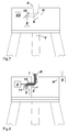
- the pattern 9 is the outline on the walls of the planned kitchen illustrated in figure 2 . With this projection, it may be visualised at the real scene where a planned construction will be positioned. In figure 3 the whole outline 9 of the kitchen is shown, however,-dependent on the angle of projection of the laser projector and dependent on the position of the laser scanner relative to the surfaces of the scene - only part of the pattern may be able to screen.
- FIG. 4 shows, further information, such as positional, height or length declarations, may be extracted from the projection data P or may be the projection data P. These information are then projected as part of the pattern 9.
- figure 5 shows construction steps with parameters as pattern 9.
- a construction worker has a visual support when accomplishing the construction steps. It is, particularly, possible to immediately perform the drills/milling at the right position, or to trace the pattern with a pencil and perform the steps at a later stage.
- Figures 3, 4 , and 5 are only exemplary embodiments of the pattern 9.
- Other projection information may be more detailed instruction texts, environmental parameters, tool selection, animations (moved pictures, video sequence), etc.
- Figure 6 shows a laser scanner 1 according to the invention.
- the scanner comprises a body 2 and a base 3 mounted on a tripod 30.
- a controlled, motorised relative rotation between body 2 and base 3 is provided around axis V.
- the body 2 comprises an emitting unit 4, a receiving unit 5, a directing unit 6, and a projector 8, wherein emitting unit 4 and receiving unit 5 are combined as one part in this example.
- a dichroic element 10 is positioned in the beam path in order to allow to pass transmission rays T from the emitting unit 4 and reception rays R towards the receiving unit 5, and on the other hand to direct rays from the projector 8 to the directing unit 6 (this functionality will be described with figure 7 ).
- the directing unit 6 is mounted in the body so that it is rotatable around an elevation axis H by a motor, and thereby directing a transmission beam T coming from the emitting unit 4 towards the environment of the scanner, and directing a reception beam R coming from the environment back to the scanner, wherein said directing takes place in a spinning manner.
- Figure 7 shows the laser scanner 1 of figure 6 , wherein the directing unit 6 is fixedly positioned in a predetermined orientation to direct the pattern 9 coming from the projector 8 to a specific place.
- An azimutal position may be set by rotating the body relative to the base around axis V.
- the directing unit 6 may rotate while cooperating with the projector 8 in a clocked manner.
- a further tractability of the pattern 9 may - to a certain extent - also be provided by the projector itself.
- the translucent mirror 10 reflects essentially all light from the projector 8 towards the directing unit 6.
- the scanning unit (4,5) is not active while projector 8 is screening the pattern 9 towards the scene.
- Figure 8 shows another embodiment of a laser scanner 1 according to the invention.
- the projector 8 is arranged on the body of the laser scanner 1, and the emitting unit 4 and the receiving unit 5 are separated.
- An optical element 11 focuses the reception beam R for the receiving unit 5.
- the translucent mirror 12 allows transmission beam T to pass, but reflects reception beam R towards the receiving unit 5.
- the projector 8 is arranged on the body 2 of the laser scanner.
- the projector 8 is configured to be controlled in a rotatory position about axis H'.
- Figure 9 shows a further embodiment of a laser scanner according to the invention.
- the laser projector 8 is arranged in the other side of the body, where the directing unit 6 is mounted.
- the projecting light now hits the directing unit 6 from the opposite side.
- the directing unit 6 is configured as a glass-bodied prism and the tilted surface acts as a mirror from the inside of the prism. Entry into and exit from the prism, however, is allowed for the projection light 9 through the according surfaces.
- the directing unit 6 axis H
- the body axis V
- FIG. 10 A further embodiment of a laser scanner according to the invention is shown in figure 10 .
- the directing unit 6 is distinguishing from the one in figure 9 in that an optical deflection element 13 is built inside the unit 6, which directs the pattern 9 towards the scene.
- the tilted surface of the directing unit 6 is a continuous mirror.
- the surface has a hole (in this case the surface is not continuous anymore), or the surface is transparent or dichroic.
- the directing unit 6 when the directing unit 6 is in the position shown in figure 10 and when said part of the surface is dichroic - in scanning mode, reception beam will be reflected as a whole, and in projecting mode, the light pattern 9 may pass the layer essentially without loss.
- the reception beam will be reflected in part, which may be tolerable in some cases.
- the optical deflection element 13 may be arranged so that the optical axis of the projection may at least in part be in line with (proceeds along) the axis of the transmission beam T and/or the axis of the reception beam R.
- the projection may have an optical axis being off-axis relative to at least one of the axis of the transmission beam T and the axis of the reception beam R.
Landscapes
- Engineering & Computer Science (AREA)
- Physics & Mathematics (AREA)
- Radar, Positioning & Navigation (AREA)
- Remote Sensing (AREA)
- Electromagnetism (AREA)
- General Physics & Mathematics (AREA)
- Computer Networks & Wireless Communication (AREA)
- Length Measuring Devices By Optical Means (AREA)
Priority Applications (1)
| Application Number | Priority Date | Filing Date | Title |
|---|---|---|---|
| EP16163039.7A EP3226029A1 (fr) | 2016-03-30 | 2016-03-30 | Scanner à laser avec projecteur référencé |
Applications Claiming Priority (1)
| Application Number | Priority Date | Filing Date | Title |
|---|---|---|---|
| EP16163039.7A EP3226029A1 (fr) | 2016-03-30 | 2016-03-30 | Scanner à laser avec projecteur référencé |
Publications (1)
| Publication Number | Publication Date |
|---|---|
| EP3226029A1 true EP3226029A1 (fr) | 2017-10-04 |
Family
ID=55646407
Family Applications (1)
| Application Number | Title | Priority Date | Filing Date |
|---|---|---|---|
| EP16163039.7A Withdrawn EP3226029A1 (fr) | 2016-03-30 | 2016-03-30 | Scanner à laser avec projecteur référencé |
Country Status (1)
| Country | Link |
|---|---|
| EP (1) | EP3226029A1 (fr) |
Cited By (13)
| Publication number | Priority date | Publication date | Assignee | Title |
|---|---|---|---|---|
| EP3450913A1 (fr) * | 2017-08-30 | 2019-03-06 | Hexagon Technology Center GmbH | Instrument de surveillance pour balayer un objet et pour la projection d'informations |
| EP3489625A1 (fr) * | 2017-11-27 | 2019-05-29 | Topcon Corporation | Instrument de surveillance |
| WO2019146598A1 (fr) * | 2018-01-24 | 2019-08-01 | 株式会社デンソー | Dispositif lidar |
| JP2019132662A (ja) * | 2018-01-30 | 2019-08-08 | シナノケンシ株式会社 | 三次元レーザー光走査装置 |
| EP3633405A1 (fr) * | 2018-10-03 | 2020-04-08 | Hexagon Technology Center GmbH | Appareil de mesure pour balayage 3d géométrique d'un environnement comportant une pluralité de canaux d'émission et de capteurs photomultiplicateur à semi-conducteurs |
| CN112445290A (zh) * | 2020-12-07 | 2021-03-05 | 兰州大学 | 一种分布式云计算机 |
| CN113325434A (zh) * | 2021-04-16 | 2021-08-31 | 盎锐(上海)信息科技有限公司 | 用于实测实量的爆点显示方法、测量系统及激光雷达 |
| CN113632454A (zh) * | 2019-03-29 | 2021-11-09 | 松下知识产权经营株式会社 | 投影系统、投影装置以及投影方法 |
| EP3936820A1 (fr) * | 2020-07-09 | 2022-01-12 | Topcon Corporation | Appareil de surveillance |
| CN114964153A (zh) * | 2022-06-16 | 2022-08-30 | 广东工业大学 | 一种基于激光定位的地基沉降监测装置及其测量方法 |
| CN115598663A (zh) * | 2022-09-30 | 2023-01-13 | 中国第一汽车股份有限公司(Cn) | 一种用于车载激光雷达的点云投影方法以及装置 |
| CN115731342A (zh) * | 2021-09-02 | 2023-03-03 | 成都极米科技股份有限公司 | 建模系统、投影系统以及建模方法 |
| CN112819805B (zh) * | 2021-02-23 | 2024-05-10 | 北京布科思科技有限公司 | 一种基于一字激光的物体位置识别方法及装置 |
Citations (3)
| Publication number | Priority date | Publication date | Assignee | Title |
|---|---|---|---|---|
| US20120057174A1 (en) * | 2010-01-20 | 2012-03-08 | Faro Technologies, Inc. | Laser scanner or laser tracker having a projector |
| EP2453205A1 (fr) * | 2010-11-11 | 2012-05-16 | Leica Geosystems AG | Dispositif de mesure et de construction pour mesurer et marquer des points spatiaux le long de courbes de niveau se déroulant horizontalement sur une surface |
| EP2980528A1 (fr) * | 2014-08-01 | 2016-02-03 | HILTI Aktiengesellschaft | Procédé de suivi et système de suivi |
-
2016
- 2016-03-30 EP EP16163039.7A patent/EP3226029A1/fr not_active Withdrawn
Patent Citations (3)
| Publication number | Priority date | Publication date | Assignee | Title |
|---|---|---|---|---|
| US20120057174A1 (en) * | 2010-01-20 | 2012-03-08 | Faro Technologies, Inc. | Laser scanner or laser tracker having a projector |
| EP2453205A1 (fr) * | 2010-11-11 | 2012-05-16 | Leica Geosystems AG | Dispositif de mesure et de construction pour mesurer et marquer des points spatiaux le long de courbes de niveau se déroulant horizontalement sur une surface |
| EP2980528A1 (fr) * | 2014-08-01 | 2016-02-03 | HILTI Aktiengesellschaft | Procédé de suivi et système de suivi |
Cited By (22)
| Publication number | Priority date | Publication date | Assignee | Title |
|---|---|---|---|---|
| EP3450913A1 (fr) * | 2017-08-30 | 2019-03-06 | Hexagon Technology Center GmbH | Instrument de surveillance pour balayer un objet et pour la projection d'informations |
| US11397245B2 (en) | 2017-08-30 | 2022-07-26 | Hexagon Technology Center Gmbh | Surveying instrument for scanning an object and for projection of information |
| EP3489625A1 (fr) * | 2017-11-27 | 2019-05-29 | Topcon Corporation | Instrument de surveillance |
| US11143505B2 (en) | 2017-11-27 | 2021-10-12 | Topcon Corporation | Surveying instrument |
| WO2019146598A1 (fr) * | 2018-01-24 | 2019-08-01 | 株式会社デンソー | Dispositif lidar |
| JP2019132662A (ja) * | 2018-01-30 | 2019-08-08 | シナノケンシ株式会社 | 三次元レーザー光走査装置 |
| EP3633405A1 (fr) * | 2018-10-03 | 2020-04-08 | Hexagon Technology Center GmbH | Appareil de mesure pour balayage 3d géométrique d'un environnement comportant une pluralité de canaux d'émission et de capteurs photomultiplicateur à semi-conducteurs |
| CN110986756A (zh) * | 2018-10-03 | 2020-04-10 | 赫克斯冈技术中心 | 具有多个传输通道和半导体光电倍增管传感器的周围环境几何3d扫描测量设备 |
| US11448733B2 (en) | 2018-10-03 | 2022-09-20 | Hexagon Technology Center Gmbh | Measuring apparatus for geometric 3D scanning of surroundings with a multiplicity of transmission channels and semiconductor photomultiplier sensors |
| CN113632454B (zh) * | 2019-03-29 | 2024-08-27 | 松下知识产权经营株式会社 | 投影系统、投影装置以及投影方法 |
| CN113632454A (zh) * | 2019-03-29 | 2021-11-09 | 松下知识产权经营株式会社 | 投影系统、投影装置以及投影方法 |
| EP3952296A4 (fr) * | 2019-03-29 | 2022-04-27 | Panasonic Intellectual Property Management Co., Ltd. | Système de projection, dispositif de projection et procédé de projection |
| US11937024B2 (en) | 2019-03-29 | 2024-03-19 | Panasonic Intellectual Property Management Co., Ltd. | Projection system, projection device and projection method |
| EP3936820A1 (fr) * | 2020-07-09 | 2022-01-12 | Topcon Corporation | Appareil de surveillance |
| CN112445290A (zh) * | 2020-12-07 | 2021-03-05 | 兰州大学 | 一种分布式云计算机 |
| CN112819805B (zh) * | 2021-02-23 | 2024-05-10 | 北京布科思科技有限公司 | 一种基于一字激光的物体位置识别方法及装置 |
| CN113325434A (zh) * | 2021-04-16 | 2021-08-31 | 盎锐(上海)信息科技有限公司 | 用于实测实量的爆点显示方法、测量系统及激光雷达 |
| CN115731342A (zh) * | 2021-09-02 | 2023-03-03 | 成都极米科技股份有限公司 | 建模系统、投影系统以及建模方法 |
| CN115731342B (zh) * | 2021-09-02 | 2025-12-09 | 成都极米科技股份有限公司 | 建模系统、投影系统以及建模方法 |
| CN114964153A (zh) * | 2022-06-16 | 2022-08-30 | 广东工业大学 | 一种基于激光定位的地基沉降监测装置及其测量方法 |
| CN114964153B (zh) * | 2022-06-16 | 2024-04-12 | 广东工业大学 | 一种基于激光定位的地基沉降监测装置及其测量方法 |
| CN115598663A (zh) * | 2022-09-30 | 2023-01-13 | 中国第一汽车股份有限公司(Cn) | 一种用于车载激光雷达的点云投影方法以及装置 |
Similar Documents
| Publication | Publication Date | Title |
|---|---|---|
| EP3226029A1 (fr) | Scanner à laser avec projecteur référencé | |
| US11397245B2 (en) | Surveying instrument for scanning an object and for projection of information | |
| US9207078B2 (en) | Device for measuring and marking space points along horizontally running contour lines | |
| EP3460394B1 (fr) | Instrument d'arpentage, système de réalité augmentée (ra) et procédé de référencement d'un dispositif de ra relatif à un système de référence | |
| JP7300948B2 (ja) | 測量データ処理装置、測量データ処理方法、測量データ処理用プログラム | |
| EP2972085B1 (fr) | Procédé et appareil pour la projection d'informations bim | |
| EP3144714B1 (fr) | Systeme d'arpentage | |
| EP3170367B1 (fr) | Système de visée d'éclairage de stade et procédé | |
| JP7313955B2 (ja) | 測量装置、測量方法および測量用プログラム | |
| US20130222791A1 (en) | Automatic measurement of dimensional data with a laser tracker | |
| US20150377606A1 (en) | Projection system | |
| US20150116691A1 (en) | Indoor surveying apparatus and method | |
| US20040122628A1 (en) | Method and device for generating two-dimensional floor plans | |
| EP3584533A1 (fr) | Système de mesure de coordonnées | |
| WO2012156277A1 (fr) | Procédé d'étalonnage pour appareil à fonction de balayage | |
| US20250306181A1 (en) | Mobile apparatus and method for capturing an object space | |
| CN103328926A (zh) | 具有自动表征改变功能的测量装置 | |
| US12524870B2 (en) | Bar arrangement inspection system and bar arrangement inspection method | |
| JP2017151026A (ja) | 三次元情報取得装置、三次元情報取得方法、及びプログラム | |
| JP7591910B2 (ja) | 測量装置及び測量方法及び測量プログラム | |
| Pfeifer et al. | The Riegl laser scanner for the survey of the interiors of Schönbrunn Palace | |
| CN219301516U (zh) | 一种测量系统 | |
| JP2025186766A (ja) | 測量システム及び測量方法 | |
| JP2024135225A (ja) | 測量装置、測量方法および測量用プログラム | |
| WO2026034299A1 (fr) | Dispositif et procédé de traitement d'informations, et programme |
Legal Events
| Date | Code | Title | Description |
|---|---|---|---|
| PUAI | Public reference made under article 153(3) epc to a published international application that has entered the european phase |
Free format text: ORIGINAL CODE: 0009012 |
|
| AK | Designated contracting states |
Kind code of ref document: A1 Designated state(s): AL AT BE BG CH CY CZ DE DK EE ES FI FR GB GR HR HU IE IS IT LI LT LU LV MC MK MT NL NO PL PT RO RS SE SI SK SM TR |
|
| AX | Request for extension of the european patent |
Extension state: BA ME |
|
| STAA | Information on the status of an ep patent application or granted ep patent |
Free format text: STATUS: THE APPLICATION IS DEEMED TO BE WITHDRAWN |
|
| 18D | Application deemed to be withdrawn |
Effective date: 20180405 |